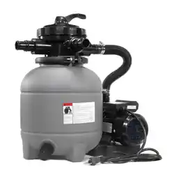
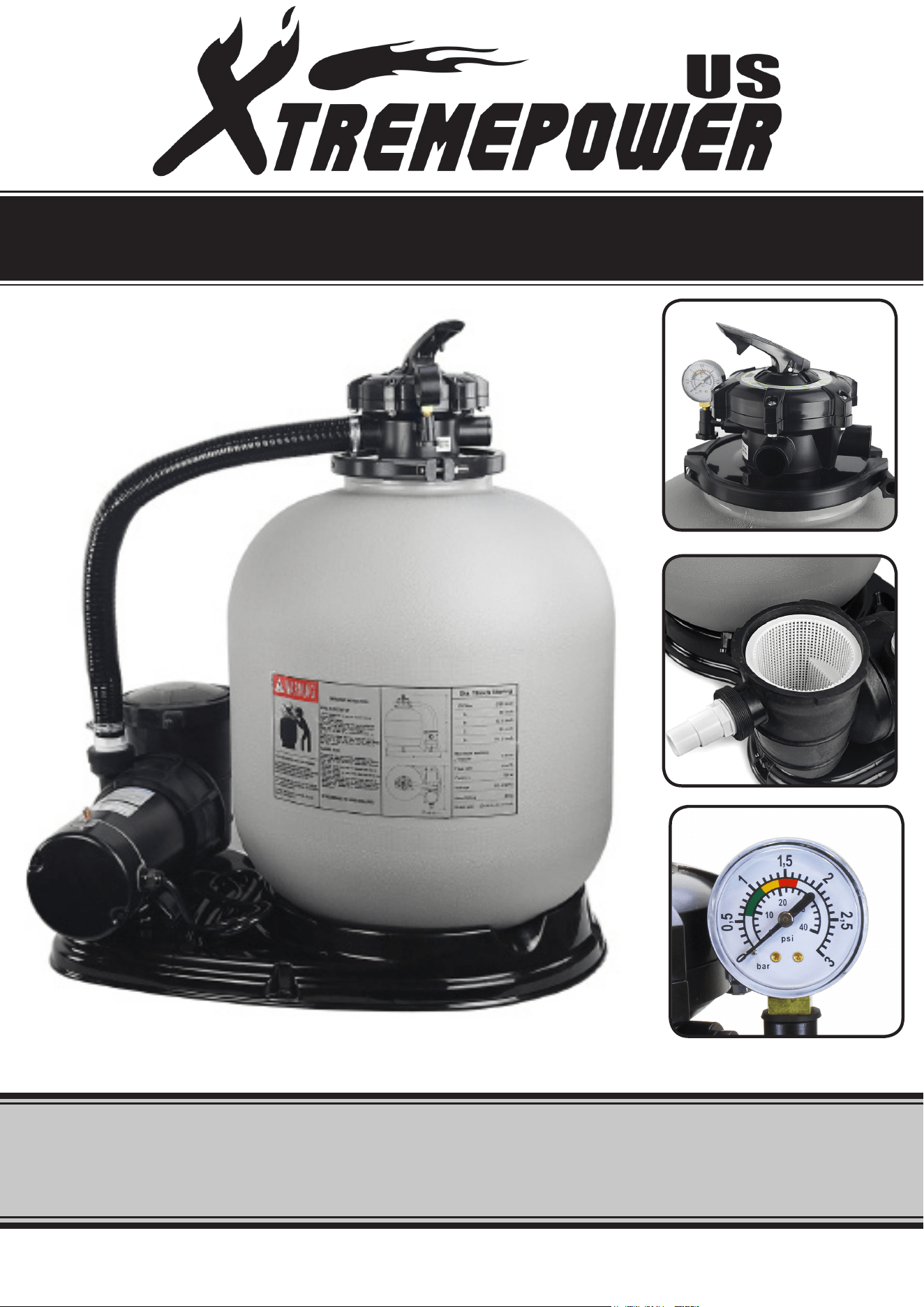
1.5HP ABOVE GROUND POOL PUMP & 19” 4500GPH SAND FILTER
SAVE THIS MANUAL: KEEP THIS MANUAL FOR SAFETY WARNINGS, PRECAUTIONS, ASSEMBLY,
OPERATING, INSPECTION, MAINTENANCE AND CLEANING PROCEDURES. WRITE THE PRODUCT’S
SERIAL NUMBER ON THE BACK OF THE MANUAL NEAR THE ASSEMBLY DIAGRAM (OR MONTH
AND YEAR OF PURCHASE IF PRODUCT HAS NO NUMBER).
OWNER’S MANUAL AND SAFETY INSTRUCTIONS
ITEM #75032
FOR QUESTIONS PLEASE CALL OUR CUSTOMER SUPPORT: (909) 628 0880 MON-FRI 9AM TO 3PM PST
GENERAL SAFETY WARNINGS
SERIOUS BODILY INJURY OR DEATH CAN RESULT IF THIS PUMP AND SAND FILTER IS NOT
INSTALLED AND USED CORRECTLY. INSTALLERS, POOL OPERATORS AND POOL OWNERS
MUST READ THESE WARNINGS AND ALL INSTRUCTIONS BEFORE USING THIS PUMP AND
SAND FILTER.
SAFETY
Most states and local codes regulate the construction, installation, and operation of public pools and
spas, and the construction of residential pools and spas. It is important to comply with these codes,
many of which directly regulate the installation and use of this product. Consult your local building
and health codes for more information.
IMPORTANT: Attention Installer: This Installation and User’s Guide contains important
information about the installation, operation and safe use of this pump and sand lter. This
Guide should be given to the owner and/or operator of this equipment.
1
The sand lters are designed to work with water temperature > 0° C and < than 45 0° C.
The lter should never be operated outside of these temperatures or damage may occur. The
installation should be carried out in accordance to the safety instructions of swimming pools and
the specic instructions for each facility.
A pool or spa pump must be installed by a qualied pool and spa service professional in
accordance with the National Electrical Code and all applicable local codes and ordinances.
Improper installation may create an electrical hazard which could result in death or serious
injury to pool users, installers, or others due to electrical shock, and may also cause damage to
property
To reduce the risk of injury, do not permit children to use or operate this pump and sand lter.
DO NOT store chemicals around your pool. Chemical spills and fumes can weaken swimming
pools and/or spas.
Any modications of this equipment of the lter requires prior consent from the supplier’s
original replacement and accessories authorized by the manufacturer to ensure a high level
of safety. The supplier assumes no liability for any damage or injuries caused by unauthorized
replacement parts and/or accessories. In the even of defective operation or fault, contact the
supplier or the nearest authorized service agent.
When setting up pool water turnovers or ow rates the operator must consider local codes
governing turnover as well as disinfectant feed ratios
DO NOT increase pump size; this may increase the ow rate through the system and exceed
the maximum ow rate stated on the drain cover.
Pumps improperly sized or installed or used in applications other than for which the pump was
intended can result in serious personal injury or death. These risks may include but not be
limited to electric shock, re, ooding, suction entrapment or serious injury or property damage
caused by a structural failure of the pump or other system component
IMPORTANT SAFETY INFORMATION
2
HIGH PRESSURE FROM THE SAND FILTER CAN CAUSE SEVERE INJURY OR MAJOR PROPERTY
DAMAGE DUE TO TANK SEPARATION. RELEASE ALL PRESSURE AND READ INSTRUCTIONS
BEFORE WORKING ON THE SAND FILTER. IF THE FILTER CLAMP IS ADJUSTED UNDER
PRESSURE, THE TANK CAN SEPARATE, CAUSING SERIOUS INJURY OR MAJOR PROPERTY
DAMAGE.
PUMPS REQUIRE HIGH VOLTAGE WHICH CAN SHOCK, BURN, OR CAUSE DEATH. BEFORE
WORKING ON PUMP! ALWAYS DISCONNECT POWER TO THE POOL PUMP AT THE CIRCUIT
BREAKER BEFORE SERVICING THE PUMP. FAILURE TO DO SO COULD RESULT IN DEATH OR
SERIOUS INJURY TO SERVICE PERSON, POOL USERS OR OTHERS DUE TO ELECTRIC SHOCK.
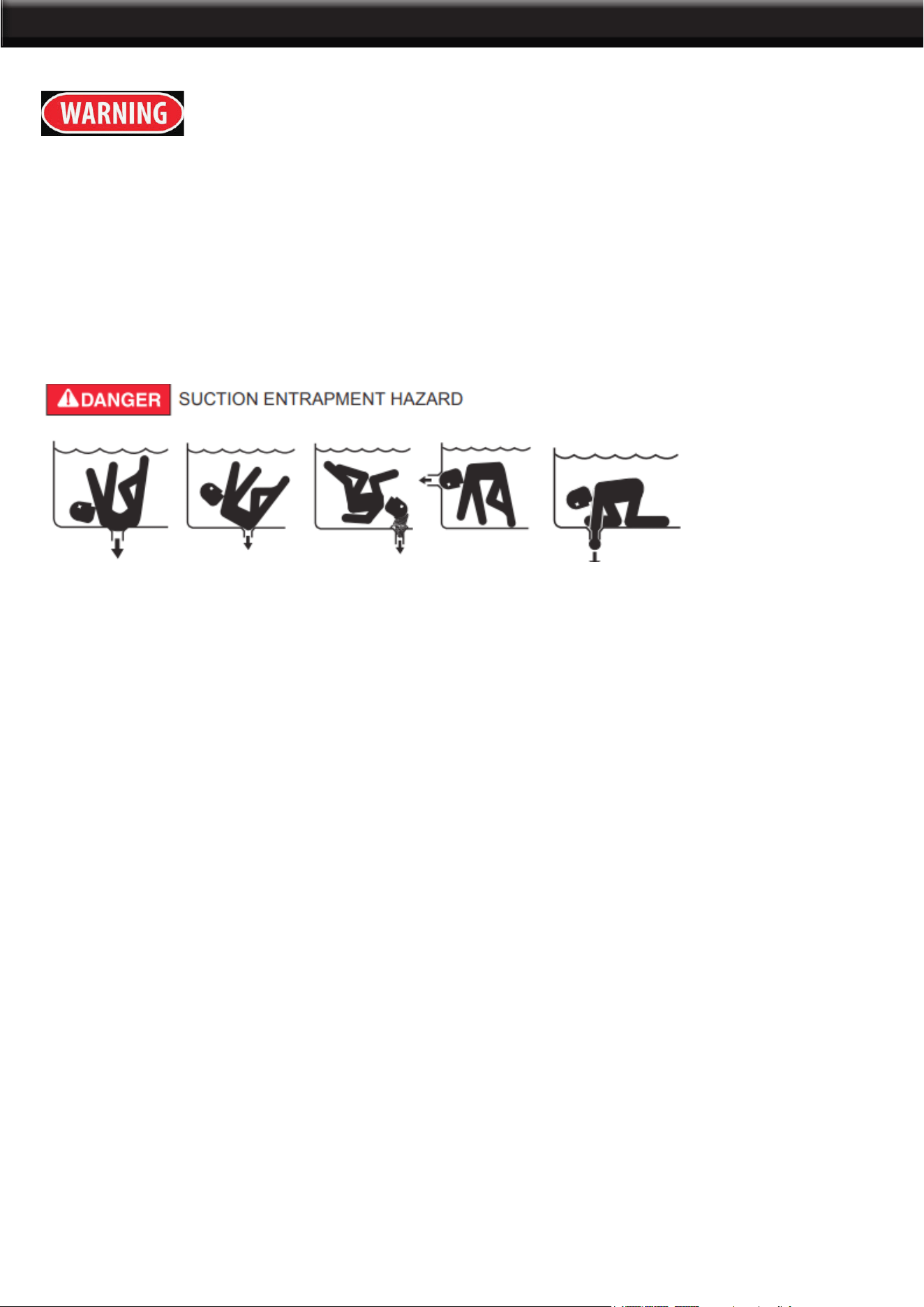
POOL AND SPA PUMPS MOVE LARGE VOLUMES OF WATER, WHICH CAN POSE EXTREME
DANGER IF A PERSON;S HAIR COMES IN PROXIMITY TO A DRAIN THAT IS NOT THE PROPER
SIZE FOR THE PUMP OR PUMPS.
The Virginia Graeme Baker Pool and Spa Safety Act imposes certain new requirements on owners and
operators of swimming pools and spas. Pools or spas constructed on or after December 20, 2008, shall
utilize:
(A) No submerged suction outlets, a gravity drainage system with ASME/ANSI cover(s), one or more
unblock-able outlets; or
(B) A multiple main drain system without isolation capability with suction outlet covers that meet ASME/
ANSI A112.19.8 Suction Fittings for Use in Swimming Pools, Wading Pools, Spas, and
Hot Tubs and either:
(I) A safety vacuum release system (SVRS) meeting ASME/ANSI A112.19.17 Manufactured Safety
Vacuum Release Systems (SVRS) for Residential and Commercial Swimming Pool, Spa, Hot Tub, and
Wading Pool Suction Systems and/or ASTM F2387 Standard Specication for Manufactured Safety
Vacuum Release Systems (SVRS) for Swimming Pools, Spas and Hot Tubs or
(ii) A properly designed and tested suction-limiting vent system or
(iii) An automatic pump shut-off system.
Pools and spas constructed prior to December 20, 2008, with a single submerged suction outlet shall
use a suction outlet cover that meets ASME/ANSI A112.19.8 and either:
(A) A multiple main drain system without isolation capability, or
(B) A safety vacuum release system (SVRS) meeting ASME/ANSI A112.19.17 and/or ASTM F2387, or
(C) A properly designed and tested suction-limiting vent system, or
(D) An automatic pump shut-off system, or
(E) Disabled submerged outlets, or
(F) Suction outlets shall be recongured into return inlets.
IMPORTANT SAFETY INFORMATION

3
This lter operates under high pressure. When any part of the circulating system (e.g., clamp, pump, lter,
valves, etc.) is serviced, air can enter the system and become pressurized. Pressurized air can cause the
lid or control valve to separate which may result in serious injury, death, or property damage. To avoid this
potential hazard, follow these instructions.
1. Before repositioning valves and before beginning the assembly,
disassembly, or adjustment of the clamp or any other service of the circulating system:
(a) Turn the pump off and shut off any automatic controls to ensure the system is not inadvertently started
during the servicing;
(b) Open manual air relief valve;
(c) Wait until all pressure is relieved, pressure gauge must read zero (0).
2. Whenever installing the filter clamp, follow the filter valve and clamp installation instructions exactly.
3. Once service on the circulating system is complete, follow system restart instructions exactly.
4. Maintain circulation system properly. Replace worn or damaged parts immediately (e.g., clamp,
pressure gauge, relief valve, o-rings, etc.).
5. Be sure that the filter is properly mounted and positioned according to instructions provided.
Failure to operate your lter system or inadequate ltration can cause poor water clarity obstructing
visibility in your pool and can allow diving into or on top of obscured objects, which can cause serious
personal injury or drowning.
This lter operates under pressure. With the valve clamped properly and operated without air in the
system, this lter will operate in a safe manner. Air entering the lter and the valve not clamped correctly
can cause the valve to separate, which could cause serious personal injury and/or property damage.
Always turn pump off before changing valve positions. Changing valve positions while the pump is running
can damage the control valve, which may cause serious injury or property damage.
Chemical fumes and/or spills can cause serious corrosion to the lter and pump structural components.
Structurally weakened components can cause lter, pump or valve attachments to separate and could
cause serious bodily injury or property damage. High voltage can cause serious or fatal injury. Always
install a suitable GFCI at the power source of this unit as an added safety precaution. Article 681-31 of the
NEC requires that a GFCI be used if this pump is used with a storable pool.
NEVER work on the pump while it is running or power is still connected. High voltage can cause
serious or fatal injury. A suitable ground fault interrupter should always be installed at the power supply
source of this unit. Be sure to ground the motor before connecting to electrical AC power supply. Failure
to ground the motor can cause serious or fatal electrical shock hazard. DO NOT ground to a gas supply
pipe line.
FOR CORD AND PLUG CONNECTED UNITS: Connect only to a ground type receptacle protected
by a Ground Fault Circuit Interrupter (GFCI). Contact a qualied electrician if you cannot verify that the
receptacle is protected by GFCI. Do Not Bury Cord. Locate cord to minimize abuse from lawn mowers,
hedge trimmers, and other equipment. To reduce the risk of electrical shock, replace damaged cord
immediately. To reduce the risk of electrical shock, Do Not Use an extension cord to connect unit to
electrical supply; provide a properly located outlet.
IMPORTANT SAFETY INFORMATION

4
SAND FILTRATION WORKING PRINCIPLE
Incoming water from the piping system is automatically directed by the multi-port valve to the top of the
lter bed. As the water is pumped through the lter sand, dirt and debris are trapped by the lter bed, and
ltered out. The lter water is returned from the bottom of the lter tank., through the multi-port and back
through the piping system .
PREPARATION BEFORE INSTALLATION
1. Position the lter as close to the swimming pool / spa as possible.
2. The lter should be placed on a level concrete slab, very rm ground, or equivalent. Ensure that the
ground will not subside to prevent any strain to the attached plumbing.
3. Position the lter so that the piping connections, Multi-Port Valve and winter drain is convenient and
accessible for operation, servicing and winterizing.
4. Ensure that the compliance label is facing the front to allow easy identication in the case of
service difculties.
INSTALLATION
WARNING: This product should be installed and serviced only by a qualied professional.
1. Put the filter tank on the base. Turn the filter tank to the right to tighten it. Position the outlet drain plug
so it is facing outside for easy operation.
2. Before filling the filter media into the filter vessel, do a visual check of the laterals. Look for broken or
loose laterals. Replace if necessary. The laterals of side-mount valve sand filter are all installed.
3. Match the Raised Point of the laterals to Folding Umbrella lateral holder, insert the laterals and turn 90º
clockwise. Listen for a sound to confirm the lateral is in place.
4. Make sure the air release hose is running along side the body of the lateral holder. One end of the air
release hose MUST
be out of the sand. DO NOT bury the air release hose in the sand.
5. To eliminate stress on the laterals, fill the filter vessel with enough water to provide a cushioning effect
when the filter sand is poured in.
6. Use Sand Shield to protect the filter top mount and make sure the central stem pipe has been fully
covered.
7. Carefully pour the exact amount of sand into the filter vessel. DO NOT allow sand to go into the stem
pipe. DO NOT damage the filter top mount or it can cause a leak.
8. Put the O-Ring on the top mount valve and then connect the valve on the filter vessel. The stem pipe
should be straight and aligned with the top mount valve. Tighten the flange clamp on the valve. NOTE: The
flange clamp should be in place and tight or it could cause injuries.
9. To connect the pump to the base, use the screws from the pump hardware pack.
10. Adjust the valve position. The pressure hose connects to the pump output/input valve.
11. The other two connection ends of the valve connect to the swimming pool and the drain outlet hose.
INSTALLATION

5
INSTALLATION NOTES
1. Make sure the filter is operating under the working pressure and using a pressure control valve when
the system is using a booster pump.
2. To aid in winterization and maintenance it is recommended that a separate gate valve be installed.
3. Minimize the length of pipe and the number of fittings to minimize friction loss to ensure maximum
efficiency.
4. Connect all plumbing to the Multi-port Valve taking care that all joints are glued or tightened securely
to prevent leaking.
5. To prevent breakage and damage to the pump and Multi-port Valve, use only pipe sealants
specifically formulated for plastics.
6. Ensure solvents are not excessively applied to fittings as this could run into O-Rings and create
sealing problems.
7. DO NOT over tighten fittings or adapters.
MULTIPORT VALVE INSTALLATION
Top Mount Sand Filters are supplied with a screw down Multi-port Valve. Supplied with the Multi-port
Valve are Flange clamp, screws and O-Ring.
1. Screw the barrel unions onto the threaded ports on the Multi-port Valve.
2. When rotating the Multi-port V
alve into position on a Top Mount Filter, leave some leeway for better
alignment of plumbing.
3. Once the Multi-port Valve is in position and the plumbing is aligned, apply the thread tape to the
barrel union thread.
4. Using a roll of Teflon tape, wrap the Teflon tape around the thread (tail) of the barrel union in a clock
wise direction.
5. Screw the barrel union into the thread of the Multi-port Valve and hand tighten. The barrel union
should be firmly threaded into the Multi-port Valve and there should be no play between the thread.
6. Once you have done this tighten the barrel union with an appropriate tool until it is tight.
7. Repeat steps until all barrel unions are firmly onto the Multi-port Valve.
8. Glue the plumbing to the Barrel unions and allow 24 hours for glue (solvent) to set before starting the
filter.
9. Test the filter and check for leaks around the threads. If leaking occurs disconnect plumbing and repeat
the steps 2 to 6 until the leak has stopped.
INSTALLATION

6
INITIAL STARTUP OF FILTER
Confirm correct amount of filter media is in tank and that all connections have been made and are
secure.
1. Depress Multi-port V
alve handle and rotate to the BACKWASH position. NOTE: To prevent damage to
control valve seal, always depress handle before turning.
2. Switch on the Pump. (OPTIONAL) If a gate valve is installed open the valve before turning on the
pump, allowing the filter tank to fill with water.
3. Once water flow is steadily exiting the waste line, run the pump for at least one minute. The initial
backwashing of the filter is recommended to remove any impurities or fine sand particles in the filter media.
4. Turn the pump off. Set the Multi-port Valve to the RINSE position. Switch on the Pump and allow it to
run until water in sight glass is clear - approximately 10 to 15 seconds.
5. Switch off the Pump. Set the Multi-port Valve to the FILTER position and Switch on the Pump. Your
filter is now operating in the normal filter mode.
6. Adjust pool suction and return valves to achieve desired flow. Check the plumbing and filter for water
leaks and tighten connections, bolts, and nuts, as required. NOTE: During initial clean-up of the pool
water, it may be necessary to backwash frequently due to the unusually heavy initial dirt load.
7. Record the pressure gauge reading (start up pressure) during initial operation. After a period of time, the
accumulated dirt and debris in the filter causes a resistance to flow, and the flow diminishes. The pressure
will start to rise and the flow of water will start diminishing. When the pressure gauge reading is 8-10 PSI
higher than the initial “Start up” pressure, it is time to backwash (clean) the filter.
CAUTION: All suction and discharge valves must be open when starting the pump. Failure to do so could
cause severe personal injury and/ or property damage. NOTE: If a pump is installed, switch the pump on
and off, instead of closing and opening the optional gate valve.
NOTE: To prevent unnecessary strain on piping system and valve, always shut off the pump before
switching lter control valve position. To prevent damage to the pump and lter and for proper operation of
they system, clean pump strainer and skimmer baskets regularly.
BACKWASHING CONDITIONS
The function of backwashing is to separate the deposited particles from lter media grains and ush
them from the lter bed. Backwashing is achieved by reversing the ow of water through the lter bed at
a fairly high ow rate. This high ow rate expands the lter bed and the water collects the debris taking
it to waste.
Time for backwashing is determined by the following conditions:
1. The ow rate through the lter bed decreases until it is insufcient to meet the demand.
2. The removal efciency of the lter bed decreases to the point where the efuent quality deteriorates
and is no longer acceptable.
3. When the pressure gauge reading is 8-10 PSI higher than the start up pressure.
4. If the lter is connected to the water main, pressure rise is not an accurate indicator as water main
pressure tends to uctuate. It is best to rely on the actual ow rate.
NOTE: We recommend that you backwash a swimming pool sand lter in a residential installation at least
once a month.
INSTALLATION

7
IMPORTANCE OF BACKWASHING
The importance of backwashing cannot be overstated. Dense lter media can become “packed” without
proper and frequent enough backwashing. Debris will remain trapped and create channelling within the
lter bed. This will result in the lter bed exhausting early. Moreover, if debris is not ushed from the media
grains, the lter bed will become dirtier and dirtier as time goes on until the lter operation fails.
BACKWASHING INSTRUCTIONS
1. Switch off the Pump. Close the Inlet Valve. NOTE: If a pump is installed, switch the pump on and off,
instead of closing and opening the Gate Valve.
2. Release the filter’s pressure by loosening Pressure Release Valve until the Pressure Gauge needle
drops to zero <0>.
3. Re-tighten Pressure Release Valve.
4. Depress and turn Handle to the BACKWASH position. In the BACKWASH position, the water flow is
automatically reversed through the filter so that it is directed to the bottom of the filter vessel, up through the
sand, flushing the previously trapped dirt and debris out the waste line.
5. Switch on the Pump. Backwash water will flow out through drain pipe.
6. When the backwash water in the sight glass appears clear, switch off the Pump.
7. Depress and turn the handle to the RINSE position. In the RINSE position, the water flow is directed
through the filter bed and out of the filter through the backwash outlet. This process settles the filter media
bed into place and ensures any dirt or debris is rinsed out of the filter, preventing possible return to the pool.
8. Switch on the Pump. Rinse water will flow out through the drain pipe.
9. When the rinse water in the sight glass appears clear. Switch off the Pump.
10. Depress and turn the handle to the Filter position and switch on the Pump.
INSTALLATION
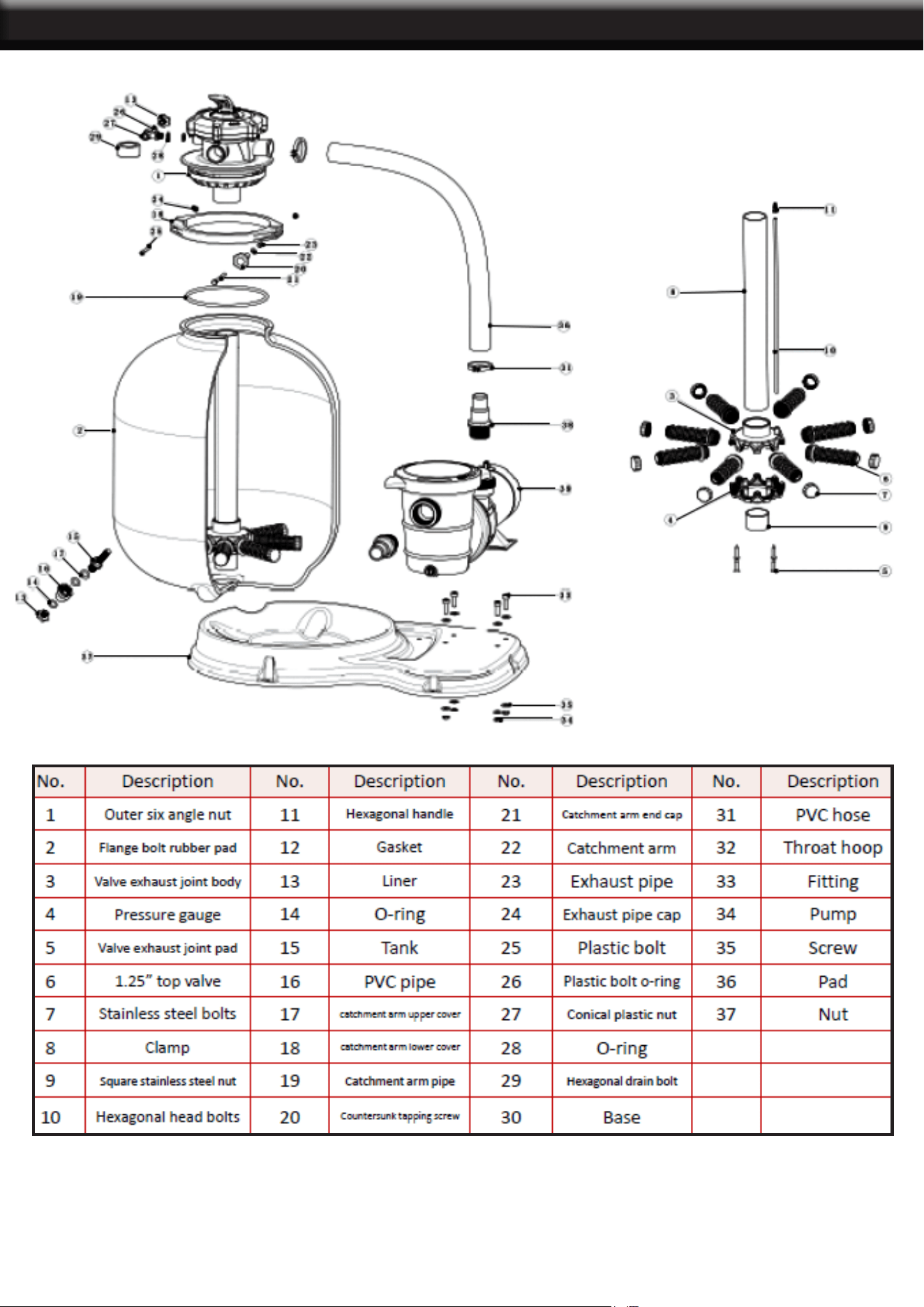
PARTS LIST
8
PLEASE READ THE FOLLOWING CAREFULLY
THE MANUFACTURER AND/OR DISTRIBUTOR HAS PROVIDED THE PARTS LIST AND ASSEMBLY
DIAGRAM IN THIS MANUAL AS A REFERENCE TOOL ONLY. NEITHER THE MANUFACTURER OR
DISTRIBUTOR MAKES ANY REPRESENTATION OR WARRANTY OF ANY KIND TO THE BUYER
THAT HE OR SHE IS QUALIFIED TO MAKE ANY REPAIRS TO THE PRODUCT, OR THAT HE OR
SHE IS QUALIFIED TO REPLACE ANY PARTS OF THE PRODUCT. IN FACT, THE MANUFACTURER
AND/OR DISTRIBUTOR EXPRESSLY STATES THAT ALL REPAIRS AND PARTS REPLACEMENTS
SHOULD BE UNDERTAKEN BY CERTIFIED AND LICENSED TECHNICIANS, AND NOT BY THE
BUYER. THE BUYER ASSUMES ALL RISK AND LIABILITY ARISING OUT OF HIS OR HER REPAIRS
TO THE ORIGINAL PRODUCT OR REPLACEMENT PARTS THERETO, OR ARISING OUT OF HIS OR
HER INSTALLATION OF REPLACEMENT PARTS THERETO.
Note: Some parts are listed and shown for illustration purposes only and are not available
individually as replacement parts.
Record Product’s Serial Number Here:
Note: If product has no serial number, record month and year of purchase instead.
9
DISCLAIMER
PRODUCT MADE IN CHINA