ASSEMBLY
AND USER’S GUIDE
SKU: 75172
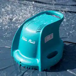
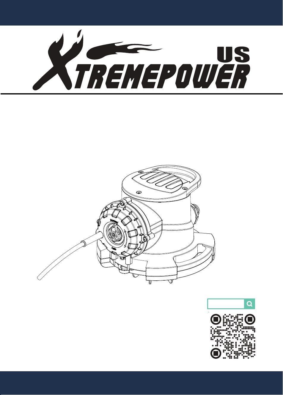
AUTOMATIC & MANUAL POOL COVER PUMP
1/2 HP
75172


1
TABLE OF CONTENT
TABLE OF CONTENTS
INSTRUCTIONS ON APPLICATION
SAFETY INSTRUCTIONS
OVERALL DIMENSION
INSTRUCTIONS ON THE EQUIPMENT
1
2
3
5
6
INTRODUCTION TO THE WORKING MODE
INTRODUCTION TO THE WORKING MODE
7
8
INSTALLATION AND USE
DAILY MAINTENANCE
9
14
TROUBLESHOOTING
SPECIFICATION
15
16
DISCLAIMER
17
CUSTOMER SERVICE
17

2
INSTRUCTIONS ON APPLICATION
Thank you for purchasing XtremepowerUS Pool Cover Pump.
Before you use the equipment for the first time, please make
sure to read this instruction manual and follow the contents of
this instruction manual. Please keep this instruction manual
appropriately for later reference.
Before trying installing, operating or repairing the product, please
read the contents of the instruction manual carefully, so as to
understand the application, restriction and potential dangers of
the product. Please follow all the safety information. In case you
do not follow these instructions, it may cause personal injury and
life & property losses.
Instructions on application:
*This Pool Cover Pump is mainly used to drain the accumulated
water on the pool cap or act as a submersible pump.
*Medium to be pumped: Non drinking water with the impurity
particle less than 0.2 INCH. Do not use it to pump corrosive sub-
stances, inflammable or explosive substances, and mud sewage
with low flowability. The temperature of the liquid pumped should
not exceed 95°F.
*The pump is only designed for household use instead of indus-
trial and commercial use.
*The manufacturer shall not undertake any liability for damage
caused by use not conforming to provisions or faulty operation.

3
SAFETY INSTRUCTIONS
Attention!
Please be noted that there may be life danger caused
by current in case of not following safety tips.
1. Recommend setting up separate branch line for the power
supply socket of the pump, and the socket power supply must
conform to: 115V / 60HZ / 3.4A, with reliable grounding.
2. Recommend setting up current type leakage current breaker
with the rated leakage current not more than 30mA for the
power supply connection of the pump.
3. The electrical connection may only be done by the electrical
professionals. Make sure to follow such a provision of the state.
4. Upon the pump use, do not use power cord to drag, move or
transport this equipment. Do not pull the power cord on sharp
edges or compress the power cord, as it may cause electric
shock or life danger arising from power cord damage.
5. Make sure to inspect whether the plug conductor is damager
or not. In case the connecting conductor is damaged, make
sure to ask electrical professionals of the authorized customer
service outlet for replacement in case of danger.
6. To avoid dangers, all the installation concerning repair and
parts replacement may only be completed by authorized service
staff.
7. Do not use the pump to pump chemicals or corrosive liquids,
which may destroy the completeness of the shell and cause
electrical short circuit. Do not use this pump for pumping gaso-
line or other liquids with low ignition point, which may cause
explosion or fire.

4
SAFETY INSTRUCTIONS
8. Individuals with physical limitations, sensory impairments,
limited understanding, or insufficient experience and knowledge
are prohibited from using this equipment without the supervision
or guidance of a qualified person who can provide instructions
on safe equipment operation and educate them about potential
hazards.
9. Children more than 8 years old may only use this equipment
in case they are supervised by their custodians or obtain the
guide on using the equipment, and understand the possible
dangers. Don’t let kids clean or repair the equipment without
supervision.
10. Do not make the pump run dry for a long time. Operation
without water may destroy the completeness of the shell and
cause electrical short circuit.
11. Upon cleaning and repairing the pump, make sure to
disconnect the pump with the main power supply first.
12. Do not use the pump in case there are people in the water.
13. When the environment temperature is lower than the freez-
ing point, please do not use the pump but store it well, other-
wise it may cause the shell breakage and cause electrical short
circuit.
5
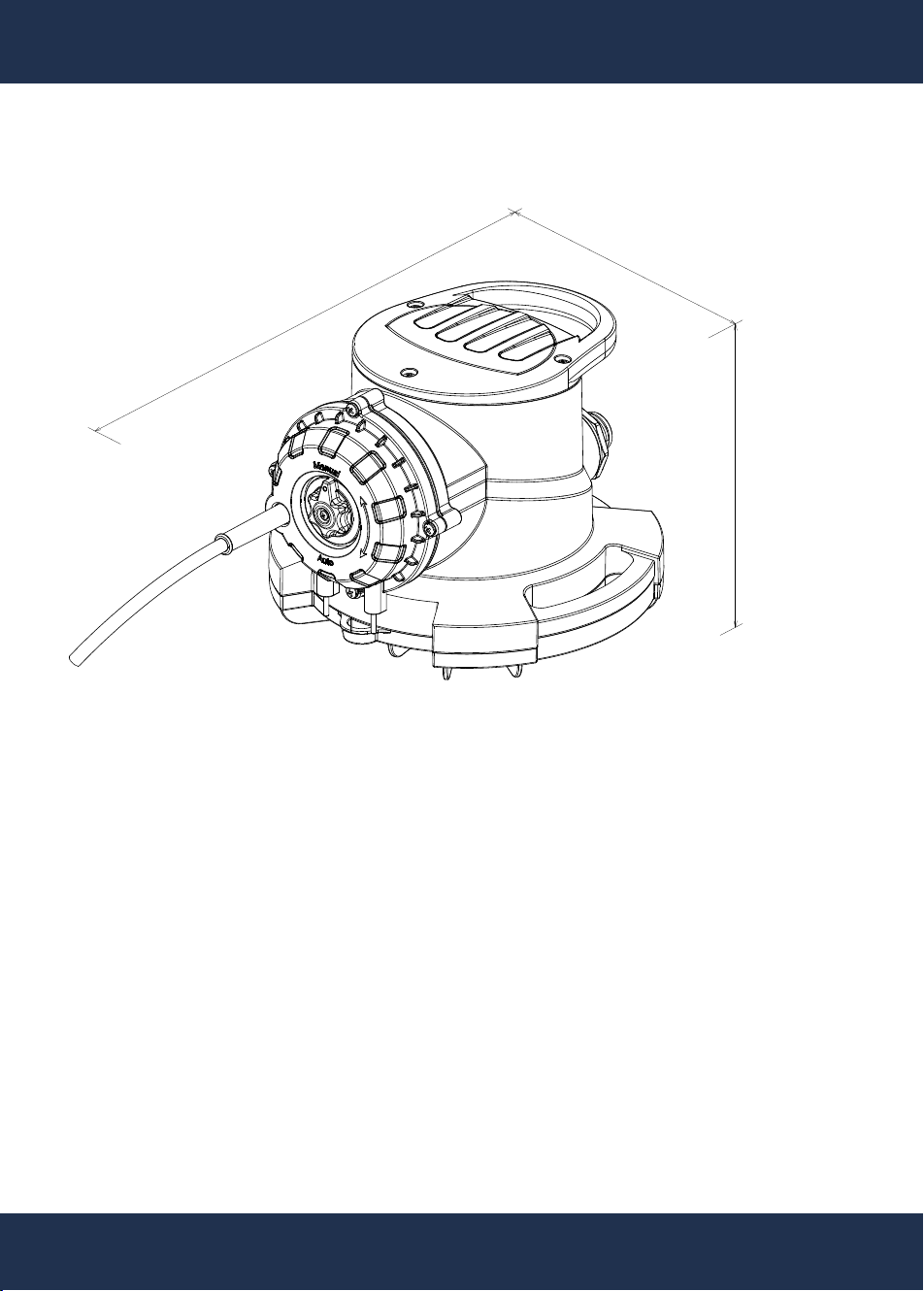
OVERALL DIMENSION
12.2 INCH
8.8 INCH
6.7 INCH
6
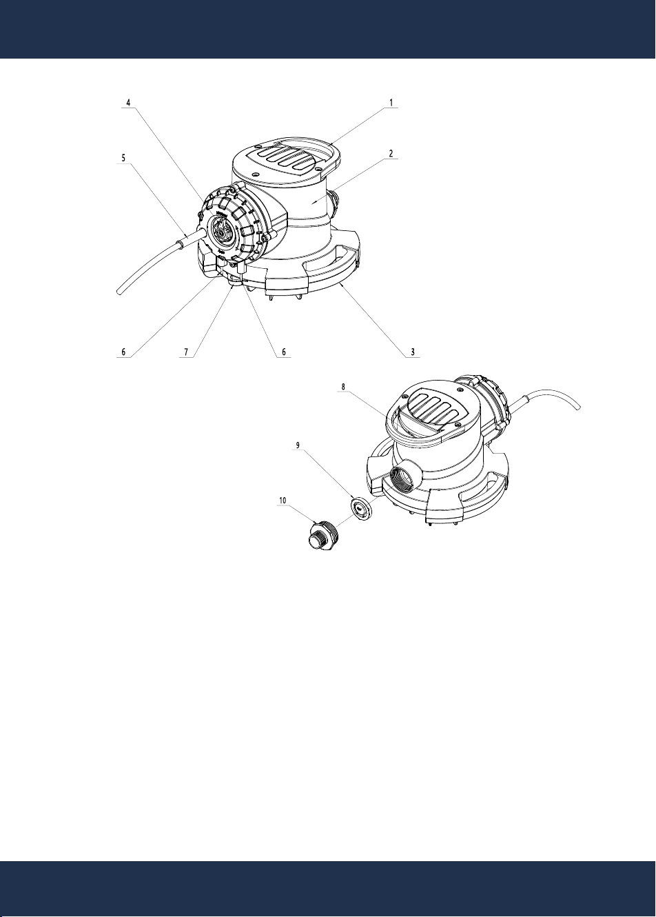
INSTRUCTIONS ON THE EQUIPMENT
1. Handle
2. Pump body
3. Base
4. Modular switch button (automatic / manual)
5. Power cord
6. Water level induction pin (two points)
7. Base hoisting rope lug
8. Air exhaust port
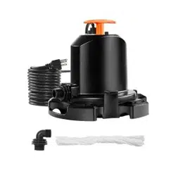
9. Single-direction check valve
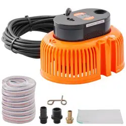
10. Output connector
Accessory: Hoisting rope (25 FT)
2
7
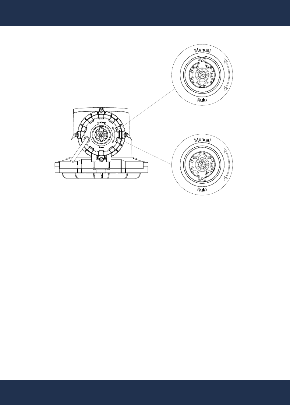
INTRODUCTION TO THE WORKING MODE
Manual control mode
1. Rotate the knob to the Manual position.
2. Plug in the power cord.
3. Under manual mode, after plugging in the power cord, the
pump will delay by 1s before starting, and the pump will run all
time until the power cord is pulled off.
Automatic control mode
1. Rotate the knob to the Auto position.
2. Plug in the power cord.
3. Under the automatic control mode, when the water level
reaches the induction pin position, the pump will delay by 1s
before starting; after the water level is lower than the induction
pin for 15S, the pump will stop automatically; circulate like this.
3
8
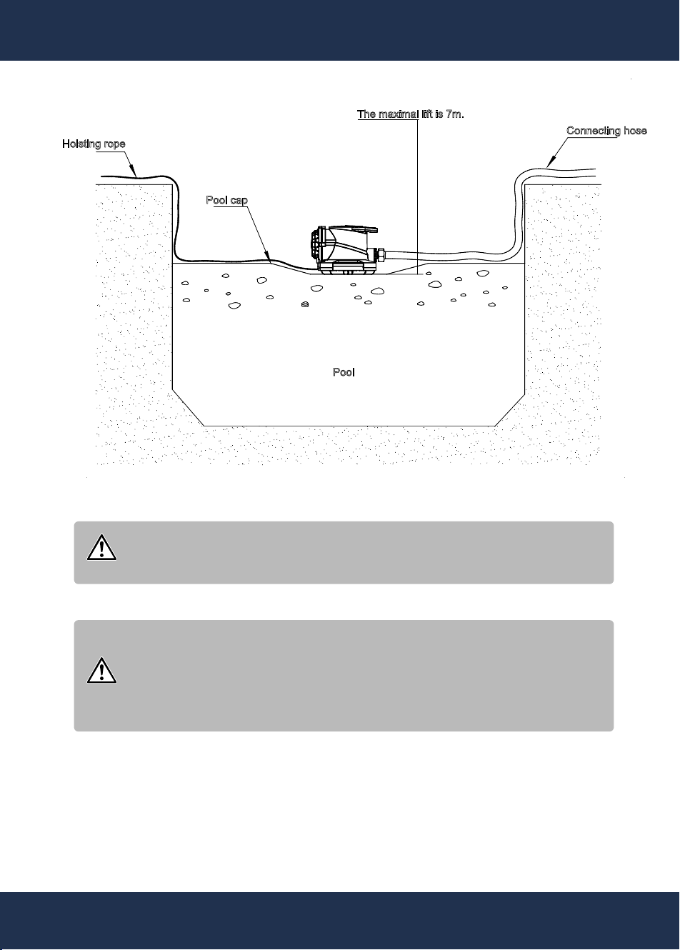
APPLICATION SCENARIO
Attention!
The pump for the pool cap is mainly used for draining
the accumulated water on the pool cap.
Attention!
Place the pump on the water accumulation place in the
center of the pool cap and drain the accumulated water
on the tarpaulin of the pool cap through the connecting
hose.
Hoisting rope
The maximal lift is 7m.
Connecting hose
Pool cap
Pool
4
9
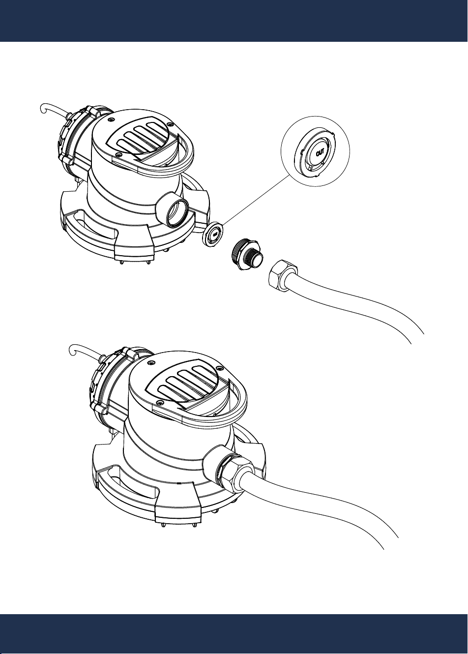
INSTALLATION AND USE
Attention: the surface with “Out” marking of the
single direction check value should be outward.
5
INSTALLATION AND USE
10
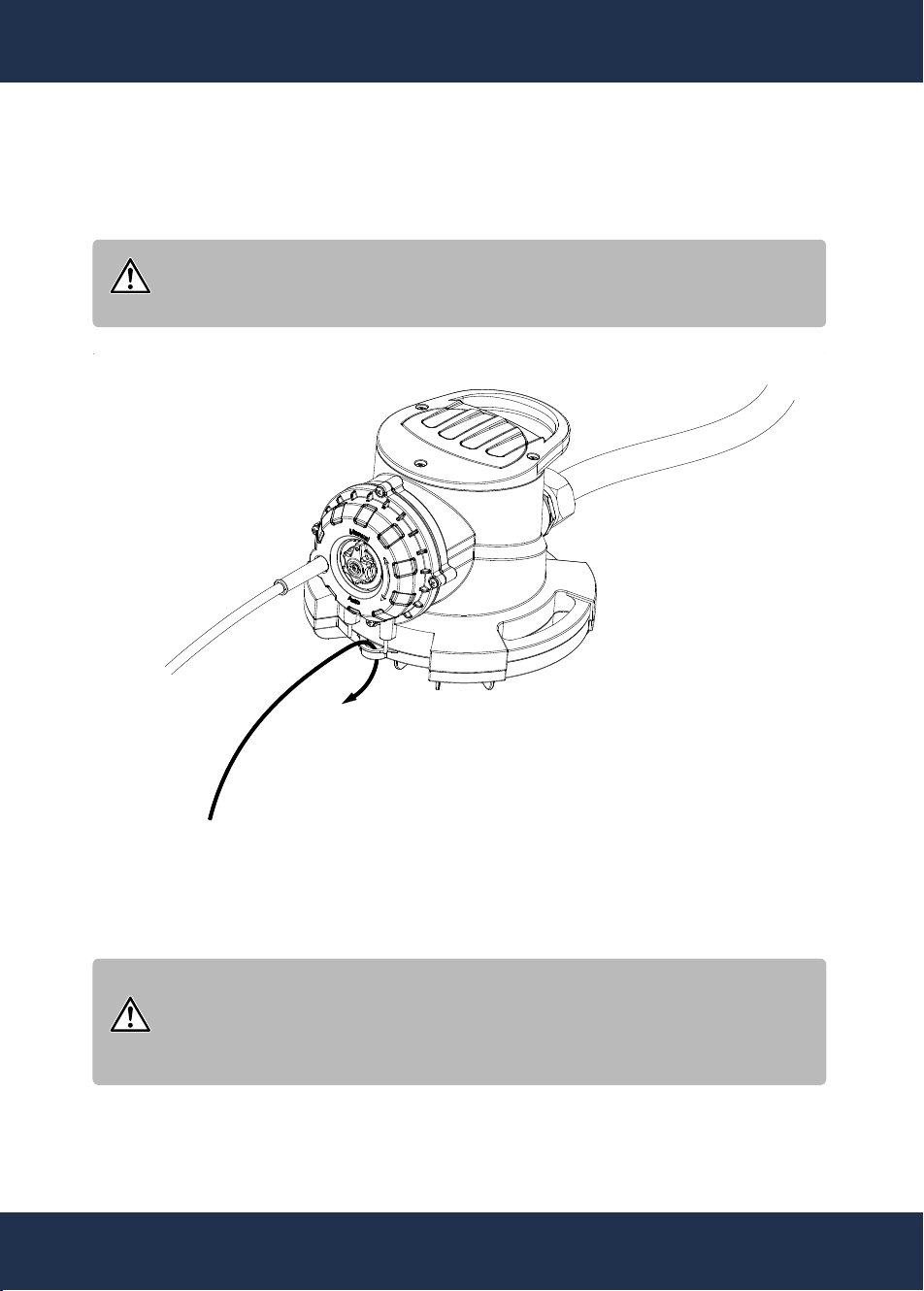
Attention!
The surface with “Out” marking of the single direction
check value should be outward.
Attention!
Do not affect the water level induction pin upon tying in
case of damaging the water level induction pin upon
pulling the pump body.
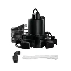
1. Place the single direction check valve in the thread hole of the
pump body, and tighten the output connector onto the water
outlet of the pump and then connect the drainage hose.
2. Run the attached hoisting rope through the hoisting rope lug,
and tie it tightly.
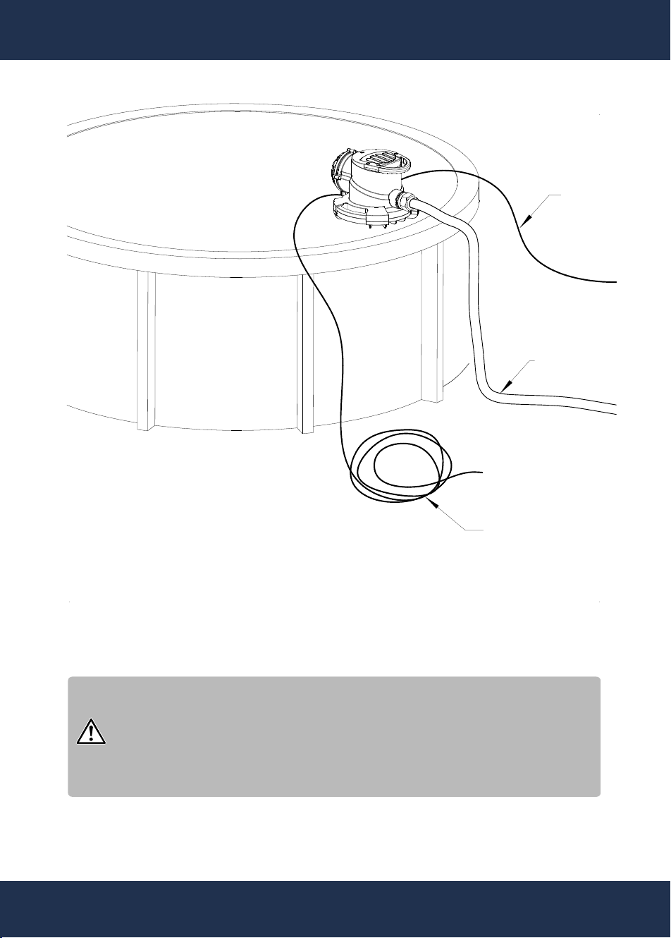
11
Power cord
Hoisting rope
Connecting hose
Attention!
Prevent the power cord, hoisting rope and connecting
hose from rubbing with the pool edge which may
cause damages, and recommend the length of the con-
necting hose to be 7.5m.
3. Place the pump on the edge of the pool cap.
INSTALLATION AND USE
11
7
INSTALLATION AND USE
10
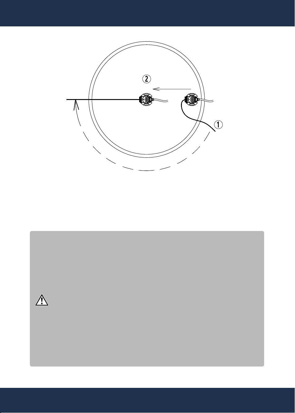
Attention!
The pump needs to be placed vertically instead of
being toppled. Do not place the pump on fragile, dam-
aged or leakage pool cap in case the processed pool
water and rainfall is pumped away from the pool by the
pump. After the pump placement, it requires inspect-
ing the pump working state daily; in case of any fault,
cut off the power supply timely in case of electric
shock. To achieve the best effect, try the best to place
the pump on the place where the water accumulates
the most easily, and make the bottom of the pump con-
tact with the tarpaulin completely, filer the impurities
effectively, clear the impurities on the tarpaulin periodi-
cally and prevent the pump obstruction effectively.
4. I. Hold the hoisting rope and walk around the pool to the
opposite side of the pump.
II. Pull the pump to the water accumulation place at the
center of the pool cap, connect the power cord, and the installa-
tion of the pump is completed.
12
7
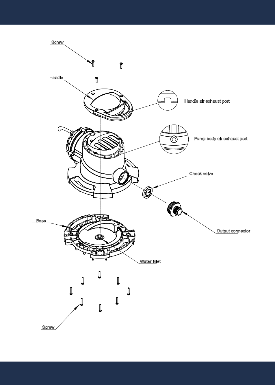
DAILY MAINTENANCE
10
Screw
Handle
Handle air exhaust port
Pump body air exhaust port
Check valve
Output connector
Base
Water inlet
Screw
13

8
14
DAILY MAINTENANCE
14
In daily use, in case of performance drop, it requires cleaning
the product.
1. In case the motor shell is completely airtight, it requires no
repair.
2. In case the pump runs normally, but fails to pump water
normally, please inspect whether the single direction
3. The impurities around the pump may drop the pump perfor-
mance or continuous operation, please clear the
impurities around the filter periodically.
4. The impurities adhered to the induction pin may cause the
pump unable to start normally, so please clear the dirt
on the induction pin periodically.
5. The impurities in the pump may cause the pump unable to
operate normally, such as obstruction, so please clear
as per the following steps:
a. Unplug the power cord.
b. Disassemble the 8 screws as shown in the diagram, and
remove the base.
c. Disassemble the impellor and diversion disc.
d. Clean all the impurities on the impellor, diversion disc and the
water inlet of the base.
e. Disassemble 3 screws as shown in the diagram and remove
the handle.
f. Clean the air exhaust port on the pump with pin or paper clip.
g. Assemble the diversion disc and impellor
h. Assemble the base.
i. Assemble the 8 screws again, and do not assemble it too
tightly or miss to assemble any of them.
j. Assemble the handle.
k. Assemble the 3 screws again, and do not assemble them too
tightly or miss to assemble any of them.
l. Plug in the power cord again.

TROUBLESHOOTING
induction pin.
There are impurities on the
Clean the induction pin
Faults Causes Troubleshooting
The pump fails to start
or run
The power supply is cut off
Fail to reach the starting water
level.
Inspect whether the water level reaches the
induction pin position.
There are foreign bodies on the
induction pin.
Clean the induction pin
Over-heating protection of the
motor
O
perate as per the Step 5 of daily maintenance
The impellor gets stuck
Operate as per the Step 5 of daily maintenanc
e
The pump fails to turn
off or run continuously
The check valve is not installed
or is damaged.
Install or replace the check valve
There are foreign bodies on the
check value
Inspect and wash the check valve
Exceed the drainage height Reduce the drainage height
M anual mode Switch to auto mode
Low pumping
efficiency or failure
The water inlet obstruction
Clean the water inlet (refer to the daily
maintenance steps)
Air exhaust port obstruction
Clean the air exhaust port (refer to the daily
maintenance steps)
Hose obstruction
Inspect the twists, replace it again or inspect
the impurities.
Exceed the drainage height Reduce the drainage height.
Check valve installation error Install the check valve again
Inspect the safety device and electrical
connection
There are moist leaves around the
sensor needle conducting electricity.
Remove leaves around the sensor needle.
15

SPECIFICATION
16
Model
Nominal Voltage
Nominal Output
Max. Height
Max. grain size
Max. Pump Rate
1/2”
75172
115 V / 60 HZ / 3.4 A
1743 GPH
25 FT
NPT 1-1/4”
Water Temperature
95 °F
Cable
SJTW 18AWG 3C-UL SHAFT: #420
25 FTCable Length
Attention!
Risk for equipment damage!
The particle size mentioned cannot be used for
simple gravel or stone, but suitable for soft, vari-
ability of particles or similar things which cannot
put into the water pump.
1/2 HP
Outlet Dia.
NPT 3/4” GARDEN HOSE
Adapter Fitting

DISCLAIMER
17
CUSTOMER SERVICE
If you have any questions about ordering our outdoor furnitures and replacement parts or other furniture
products, please feel free to contact us using the following contact information:
Customer Service and Technical Support
Phone: (909) 628-0880
Email: [email protected]
Hours of Operation: Monday – Friday, 9AM – 4PM (CST)
DISCLAIMER
PLEASE READ THE FOLLOWING CAREFULLY
The manufacturer and/or distributor have provided the parts list and assembly diagram in this manual for
reference purposes only. They do not make any representation or warranty to the buyer that they are qualified
to make repairs to the product or replace any parts of the product. In fact, the manufacturer and/or distributor
expressly state that all repairs and parts replacements should be undertaken by certified and licensed
technicians, and not by the buyer.
The buyer assumes all risk and liability arising from their repairs to the original product or replacement parts
or arising from their installation of replacement parts. It is strongly advised that qualified professionals handle
any repairs or replacements to ensure safety and proper functioning of the product. Improper installation and
operation may result in injury, property damage, or voiding of warranty. The manufacturer and/or distributor
shall not be held responsible for any accidents, damages, or malfunctions resulting from the buyer's
installation and operation of the product. It is essential to follow all safety guidelines and recommendations
provided in this manual and to seek professional assistance if unsure about the installation or operation
procedures.