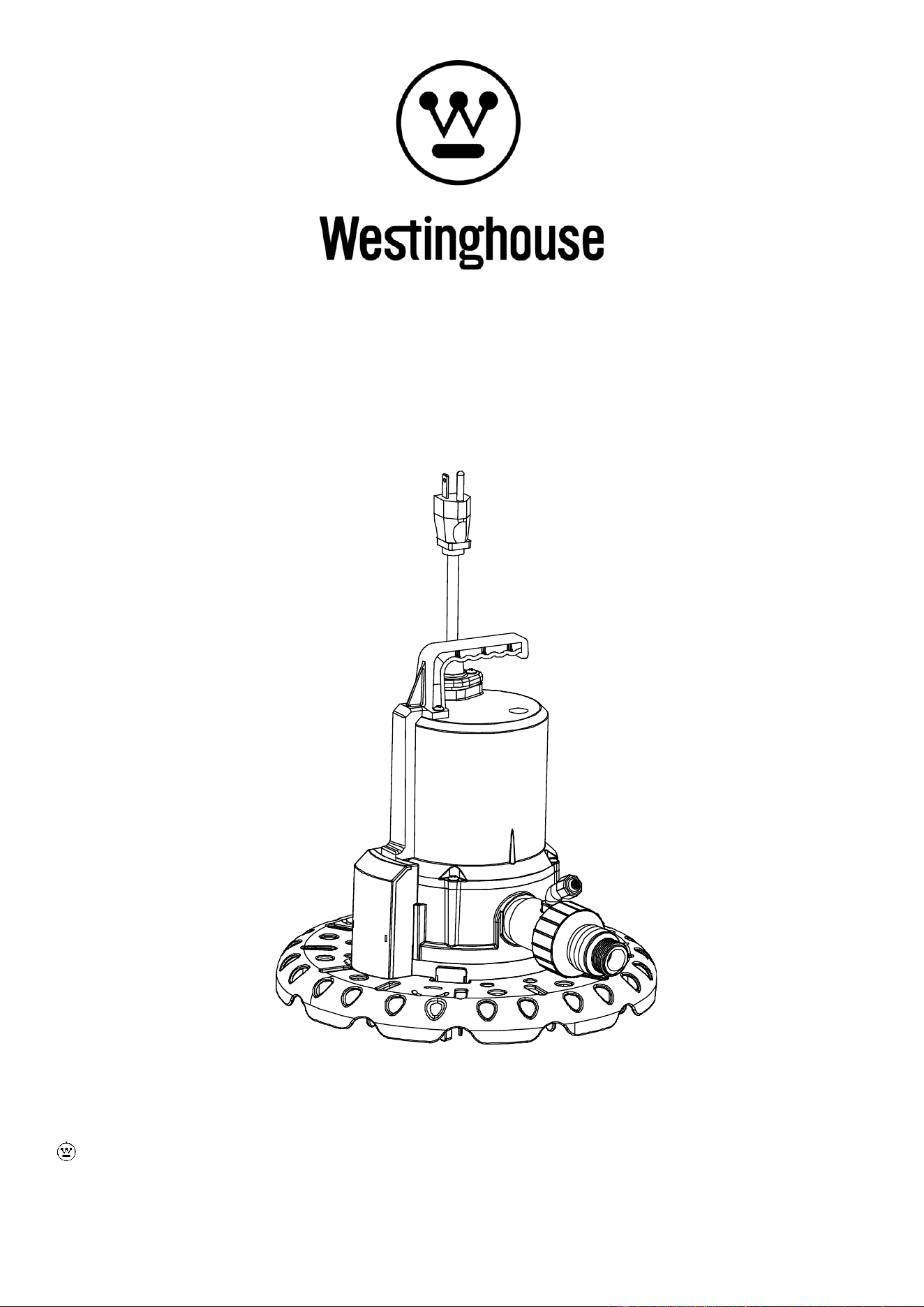
OWNER’S MANUAL
POOL COVER PUMP
Model# WHPCP
and Westinghouse are trademarks of Westinghouse Electric Corporation. Used Under License by Westinghouse
Residential Pumps. All Rights reserved.

2
PERFORMANCE
Model
HP
GPH of Water @ Total Feet Of Lift
Max. Lift
0 ft.
5 ft.
10 ft.
15 ft.
20 ft.
25 ft.
28 ft.
WHPCP
1/4
1800
1550
1320
1080
780
360
SAFETY INSTRUCTIONS
1. Do not pump flammable or explosive liquids such as oil, gasoline, kerosene, ethanol, etc. Do not use in the
presence of flammable or explosive vapors. Using this pump with or near flammable liquids can cause an explosion
or fire, resulting in property damage, serious personal injury, and/or death.
2. ALWAYS disconnect the power to the pump before servicing.
3. Do not touch the motor housing during operation. The motor is designed to operate at high temperatures. Do not
disassemble the motor housing.
4. Do not handle the pump or pump motor with wet hands or when standing on a wet or damp surface, or in water
before disconnect the power.
5. Release all pressure and drain all water from the system before servicing any component.
6. Secure the discharge line before starting the pump. An unsecured discharge line will whip, possibly causing
personal injury, and/or property damage.
7. Extension cords may not deliver sufficient voltage to the pump motor. Extension cords present a life threatening
safety hazard if the insulation becomes damaged or the connection ends fall into water. The use of an extension
cord to power this pump is not permitted.
8. Wear safety goggles at all times when working with pumps.
9. This unit is designed only for use on 115 volts (single phase), 60 Hz, and is equipped with an approved 3-conductor
cord and 3-prong grounded plug. Do not remove the ground pin under any circumstances. The 3-prong plug must
be directly inserted into a properly installed and grounded 3-prong, grounding-type receptacle. Do not use this
pump with a 2-prong wall outlet. Replace the 2-prong outlet with a properly grounded 3-prong receptacle (a GFCI
outlet) installed in accordance with the National Electrical Code and local codes and ordinances. All wiring should
be performed by a qualified electrician.
10. Protect the electrical cord from sharp objects, hot surfaces, oil, and chemicals. Avoid kinking the cord. Do not use
damaged or worn cords.
11. Failure to comply with the instruction and designed operation of this unit may void the warranty. ATTEMPTING TO
USE ADAMAGED PUMP can result in property damage, serious personal injury, and/or death.
12. Ensure that the electrical circuit to the pump is protected by a 10 Amp fuse or circuit breaker.
13. Do not lift the pump by the power cord.
14. Know the pump and its applications, limitations, and potential hazards.
15. Secure the pump to a solid base. This will aid in keeping the pump in a vertical orientation. This is critical in keeping
the pump operating at maximum efficiency. It will also help prevent the pump from clogging resulting in premature
failure.
16. Periodically inspect the pump and system components to ensure the pump suction screen is free of mud, sand, and
debris. Disconnect the pump from the power supply before inspecting.
17. Follow all local electrical and safety codes, along with the National Electrical Code (NEC). In addition, all
Occupational Safety and Health Administration (OSHA) guidelines must be followed.
18. The motor of this pump has a thermal protector that will trip if the motor becomes too hot. The protector will reset
itself once the motor cools down and an acceptable temperature has been reached. The pump may start
unexpectedly if it is plugged in.

3
19. Ensure the electrical power source is adequate for the requirements of the pump.
20. Before using the pump, check the hose for holes or excess wear, which could cause leaks, and ensure the hose is
not kinked or making sharp angles. A straight hose allows the pump to move the greatest amount of water quickly,
and also check that all hose connections are tight to minimize leaks.
21. This pump is made of high-strength, corrosion-resistant materials. It will provide trouble-free service for a long time
when properly installed, maintained, and used. However, inadequate electrical power to the pump, dirt, or debris
may cause the pump to fail. Please carefully read the manual and follow the instructions regarding common pump
problems and remedies.
22. This pump is fully automatic in operation. If the water level is over 2 in., the water detector senses water. Then the
control system built in the pump automatically starts the pump and the pump continues to run until water is pumped
down to 3/4 in. deep, and then it stops. If the water level is not over 2 in., the pump will not start.
23. Electric shock hazard! GFCI receptacles will provide protection against line to ground faults only. The ground fault
receptacle does NOT limit the magnitude of fault current and will NOT prevent an electrical shock. Replace
damaged cord immediately.
24. Risk of electric shock. This pump has NOT been tested for use in marine areas. NEVER place pump in pools while
people are in the water. Do NOT handle pump with wet hands or when standing in water or on a damp surface.
Pump is designed to be used in closed and covered pools only. Water accumulated on pool cover can cause injury
or death. Proper installation of pool cover pump and periodic maintenance is recommended. Failure to follow
COULD result in death or serious injury.
25. The unit MUST be plugged into a properly grounded GFCI outlet. Consult with a qualified electrician for proper
installation of a GFCI OUTLET.
26. Do not move, position, retrieve, or carry pump using the power cord or the discharge hose, damage to the pump or
power cord may occur. Use the handle supplied on the pump or attach a string to the strainer to position as
instructed.
PRE-INSTALLATION
APPLICATION
This portable, auto On-Off Pool Cover pump is designed for automatic removal of water, from a pool or spa cover. The
unit is equipped with a 25 ft. 3-prong grounding type power cord. The provided discharge check valve prevents short
cycling and it's 3/4” adapter can be used for convenient attachment to a standard garden hose.
Features:
Operating water depth: minimum 2 in.
TOOLS REQUIRED
Phillips
Screwdriver
Flathead
Screwdriver
Wrench
Safety
Goggles
4
MATERIALS REQUIRED (NOT INCLUDED)
NOTE: The hose and hose kit are not shown to scale.
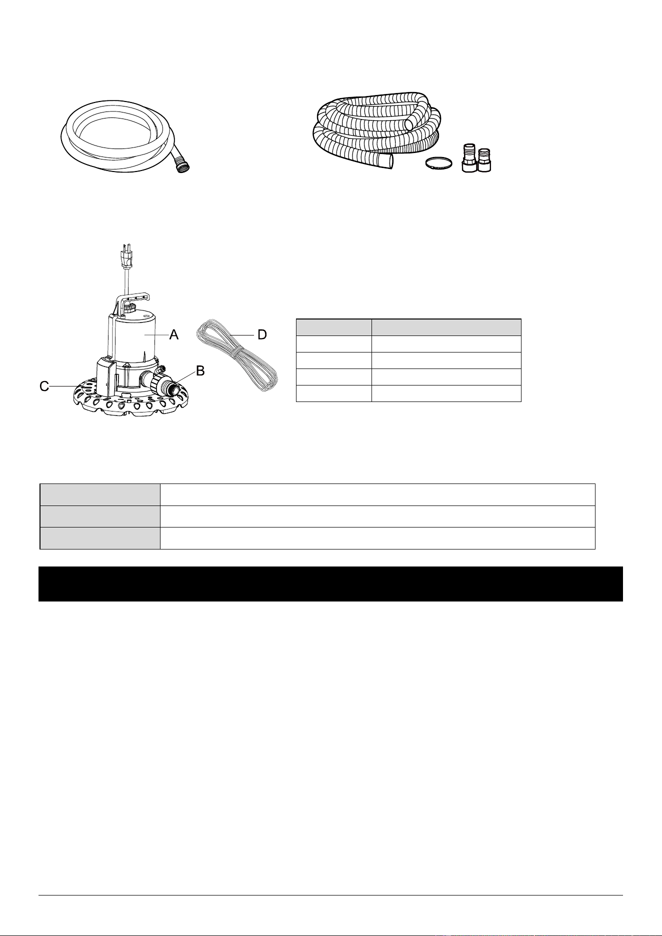
Garden Hose Sump Pump Discharge hose kit
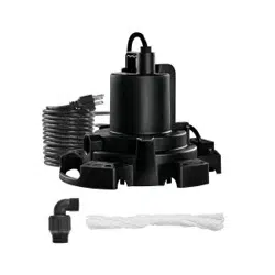
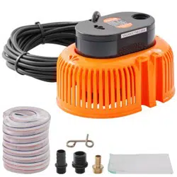
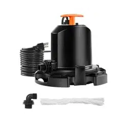
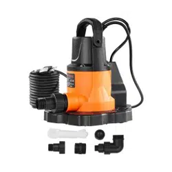
PACKAGE CONTENTS
SPECIFICATIONS
Power supply
115V, 60 HZ., 10 Amp Circuit
Liquid Temp. Range
32°F to 95°F(0°-35°C)
Discharge
1 in. male NPT or 3/4 in. garden hose thread
INSTALLATION
DANGER: Do NOT use pump if any part of the housing switch or probe is cracked, broken, or missing.
DANGER: Always unplug the pump before attempting to install, service, relocate, or perform any maintenance.
DANGER: Extension cords may not deliver sufficient voltage to the pump motor. Extension cords present a life
threatening safety hazard if the insulation becomes damaged or the connection ends fall into water. The use of an
extension cord to power this pump is not permitted.
WARNING: This unit is NOT designed for use as a sump pump or in sump applications. This unit is NOT designed for
use in septic tanks or underground vaults to pump raw sewage or effluents. NEVER use in hazardous or explosive
locations
CAUTION: Always use the handle to lift the pump. Never use the power cord to lift the pump. To avoid skin burns,
unplug the pump and allow time for it to cool after periods of extended use.
Part
Description
A
Pump
B
3/4 in. Check valve
C
Debris strainer
D
25’ Rope
5
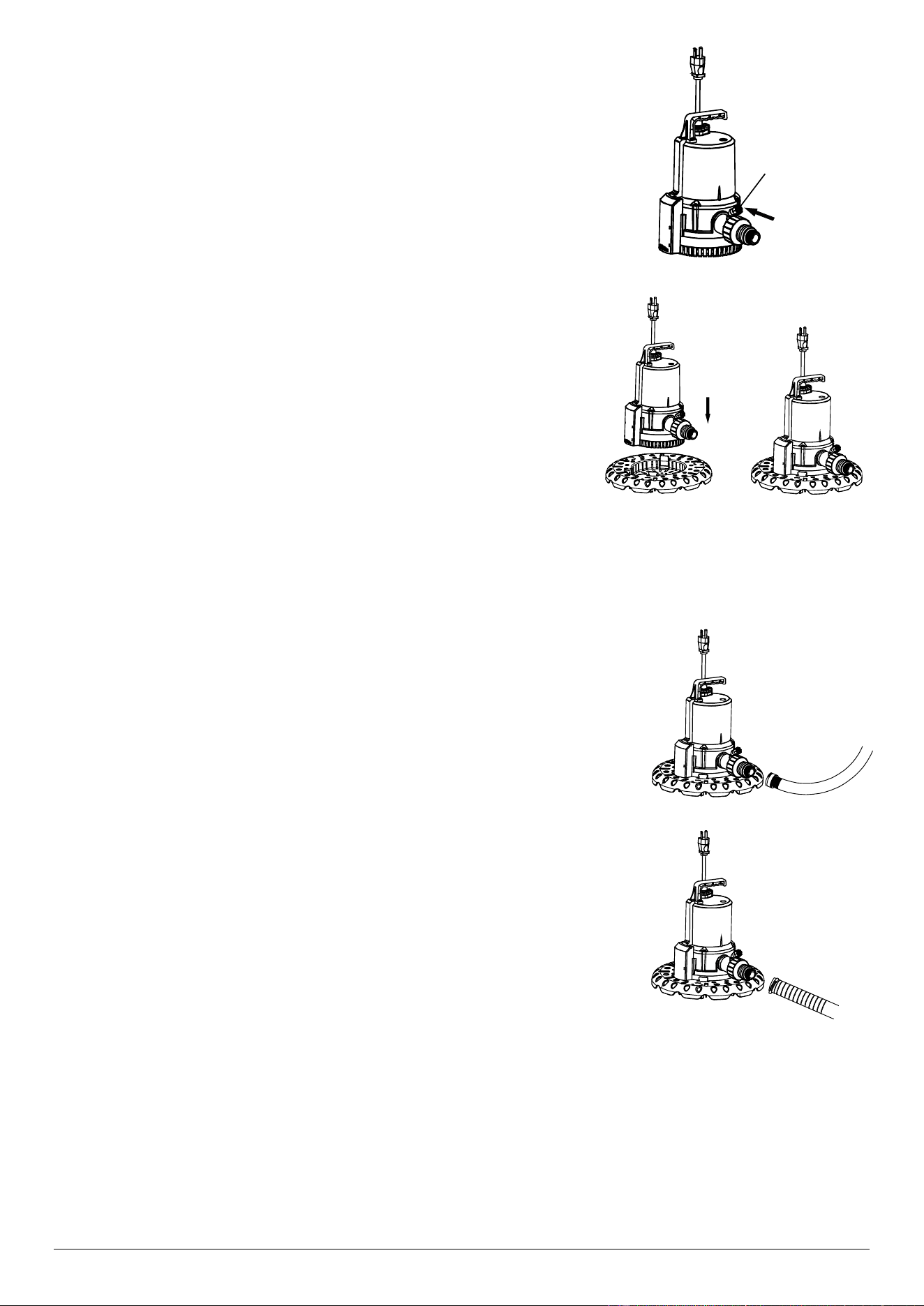
1. Connecting a check valve
Install the check valve to the pump outlet
NOTE: Be sure anti-airlock hole is pointing upward.
2. Connecting a debris strainer
Install the “snap-on” debris strainer. Begin by lining up the pump base
profile with the profile of the strainer base using the switch housing as a
guide. Tilt the pump back and guide the rear of the pump (opposite the
discharge) into the strainer base. Once the rear of the pump is in place,
gently rotate the pump down until the latch engages.
To remove debris strainer release latch and guide pump out of strainer in
the reverse motion of installation
NOTE: Always use debris strainer when placing pump on a pool cover .The
strainer helps protect the pool cover from damage, filters debris, and increases
pump stability.
3. Connecting a 3/4 in. garden hose or 1-1/4 in. hose kit
NOTE: Be sure the 3/4 in. garden hose thread connector has a rubber gasket to
minimize water leaks.
Attach a garden hose with a 3/4 in. garden hose thread (not included) to the
check valve.
If you would prefer to use a 1-1/4 in. hose kit (not included) in order to pump water
away more quickly.
WARNING: Secure the discharge hose before plugging in the pump. An unsecured
discharge hose may “whip” possibly causing personal injury, and/or property damage.
Securely attach the hose kit (not included) to the check valve.
4. Setting the pump on the pool cover
With pump unplugged set the pump on the pool cover, where water will collect. Do not set the pump directly on mud,
sand surfaces or in leaves.
NOTE: For best results make sure the pump strainer is making full contact with a clean area of the pool cover. This will
allow the strainer to properly filter debris and help prevent clogging of the pump. If necessary clear an area of the pool
cover before placing the pump.
NOTE: Do not place the pump on a weak, damaged, or leaking pool cover. Placing the pump on a damaged pool cover
could cause the cover to give way, or could allow the pump to remove treated swimming water from the pool in addition
to rainwater.
anti-airlock
hole
6
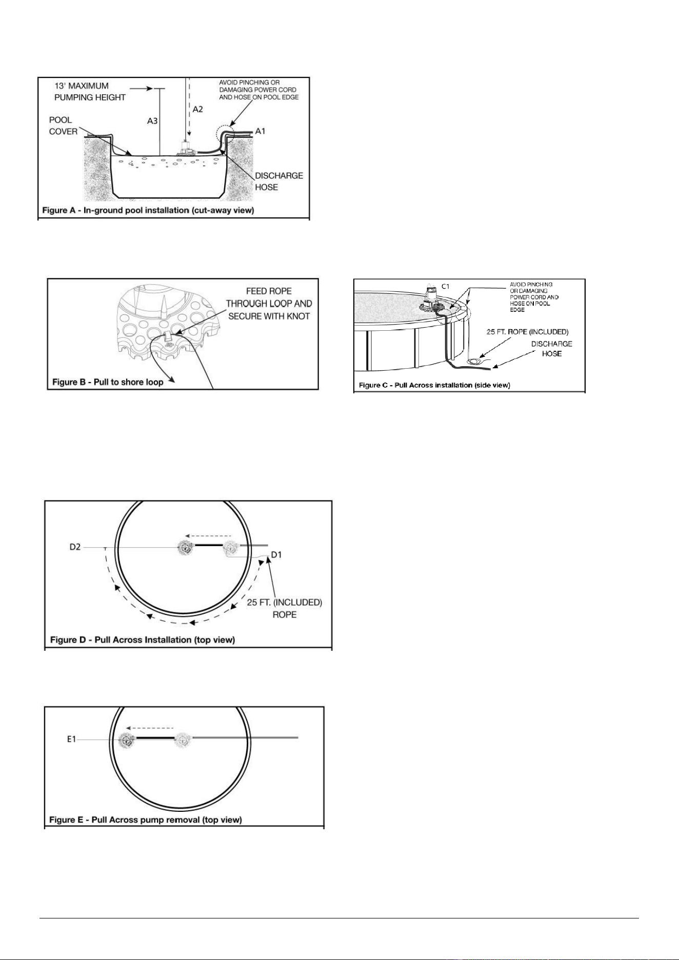
Drop-in pump application
A1. Place hose end away from pool, where water will be
displaced.
A2. Attached provided 25ft. rope to handle of pump, and
lower pump onto pool cover where water will collect.
A3. Do not exceed the 13ft. maximum pumping height for
this pump or switch may not function properly. Plug in pump
to allow for automatic operation.
For removal unplug pump and retrieve using rope.
Pull across pump installation
To aid in pump placement on pool cover, secure provided 25 ft. rope to the pull to shore loop( Figure B).
C1. Connect provided 25ft. rope to pull to shore loop (Figure B).
C2. Place pump on pool cover near edge of pool (Figure C).If flotation device is used, place pump at the lowest point on
the pool cover where water will collect.
D1. Holding the provided 25 ft. rope, walk around pool until
you are even with the pump on the opposite side.
D2. Pull the 25 ft. rope towards you until the pump is in the
center of the pool cover where water will collect. Secure
rope for easy removal (Figure E) when weather permits.
Note: Always use debris strainer when placing pump on a
pool cover. The strainer helps protect the pool cover from
damage, filters debris, and increases pump stability.
Pull across- pump removal
E1. Disconnect power to pump. Using the included 25ft.rope,
safely pull pump to edge of pool, disconnect discharge hose
and remove.

7
OPERATION
NOTE: For best pump performance, unwind the hose before starting the pump. This will help remove any kinds or binds
in the hose and allow the unit to pump with less restriction.
1. The water level must be at least 2” for the pump to cycle, prime, and operate. Water levels less than 2” will not allow
the impeller to contact water therefore no water will be pumped.
2. Plug the pump into a properly grounded 115 volt GFCI protected outlet. The pump will start automatically when the
water reaches a depth of 2”. A priming delay of 2 seconds is programmed into the control to allow time for air to
escape from the pumping chamber.
CAUTION: Use caution when positioning the pump not to damage the power cord by dragging across the edge of the
pool. Also take into consideration the placement of the discharge hose and power cord after installation. Make sure no
sharp edge can damage the power cord or discharge hose causing unsafe conditions.
3. The pump will stop automatically once water has been removed to a depth of approximately 3/4”. The pump will
NOT restart until the water depth rises to 2” or greater.
4. The pump will NOT allow itself to run dry. Once the pump detects that water is no longer being removed, it will shut
down automatically. The pump must remain upright at all times in order for the water detection to function. Do NOT
allow the pump to operate on its side or inverted The shaft seal depends on water for lubrication, allowing the pump
to remain in any other orientation than upright could cause shaft seal failure or pump failure
NOTE: Do NOT alter the pump to override the automatic water detector. The shaft seal depends on water for
lubrication. Overriding this pump feature CAN cause the pump to run dry and MAY damage the shaft seal and
cause pump failure.
CARE AND CLEANING
WARNING: Pump starts automatically. Always disconnect electric supply before attempting to install, service, relocate, or
perform any maintenance.
CAUTION: Always use the handle to lift the pump. Never use the power cord to lift the pump. To avoid skin burns, unplug
the pump and allow time for it to cool after periods of extended use.
Do
Do Not
When the power is disconnected, inspect the
pump inlets and remove all debris, then plug the
pump back into the grounded (GFCI) outlet.
Disassemble the motor housing. This motor has
NO repairable internal parts, and disassembly
may cause leakage or dangerous electrical wiring
issues.
Lift up the pump by the power cord.
Minimal service is required for this pump. The motor housing of the pump is completely sealed and requires no service.
If pump should fail to operate, perform the following troubleshooting guidelines:
1. Verify pumping height does NOT exceed 15’. If pumping height is greater than 15’, this pumps automatic feature will
not operate correctly.
2. Verify water depth is 2” or greater.
3. To verify pump is operating correctly.
a. Disconnect pump from power source.
b. Connect check valve and discharge hose to pump.
c. Immerse pump in a bucket or tub of water at least 2” in depth.
d. Place the other end of the discharge hose outside the bucket, so the water will pump out.
e. Plug power cord into a grounded 115 volt GFCI power outlet. The pump should start after 2 seconds of detecting
water. Once the pump removes the water to a depth of 3/4”, the pump will stop automatically.

8
4. To verify discharge hose is free from a blockage.
a. Connect hose to another water source such as a faucet. If water flows through hose, return to step 3a.If water is
restricted, verify discharge hose is unwound and remove all kinks, bends, or obstructions in hose.
5. If pump runs continuously, unplug the unit. Once unplugged, remove the strainer and check for debris stuck inside
the sensor body. Remove any trapped leaves, debris or dirt.
6. When temperatures drop below freezing remove pump from service and store indoors to protect pump from damage
due to ice. The pump has a unique protection circuit to protect the motor from a locked impeller condition possibly
caused by debris buildup or from a “frozen” impeller situation caused by ice formation. When the pump is activated
and a locked impeller condition is detected the unit will automatically shut down to protect the motor from
overheating. Once the pump is able to operate correctly the pump will resume normal operation.
DANGER: Do not use pump if any part of the switch housing or probe is cracked, broken or missing.
PUMPING HEIGHT
When water is pumped to an elevated position, any volume that has not reached the discharge outlet can flow back
through the pump when the pump shuts off. This back-flow can cause the water level in small areas to rise enough to
re-start the pump. The check valve included is required in this situation. For proper operation, make certain the check
valve is oriented as instructed on check valve body.
TROUBLESHOOTING
DANGER: Electrocution Hazard! Pump starts automatically. Disconnect the power before attempting any repairs. Failure to follow
WILL result in serious injury or death.
Problem
Possible Cause
Corrective Action
Pump will not start or run
1. Tripped home electrical breaker
2. GFCI tripped
3. Low line voltage
4. Defective motor
5. Dirty switch
6. Impeller obstructed
7. Inlet screen or strainer clogged
8. Priming hole plugged
1. Reset breaker
2. Check for damaged wiring or moisture
3. Contact electrician
4. Replace pump
5. Rinse out switch with clean water
6. Remove strainer, base, and impeller
platecheck for debris; clean
7. Clean inlet screen and debris strainer)
8. Clean hole, inside volute housing, with
a pin or paper clip
Pump starts and stops
too often
1. Backflow of water from piping
2. Dirty switch
3. Priming hole plugged
4. Pump is sitting uneven on pool or
spar cover
1. Install or replace check valve
2. Rinse out switch with clean water
3. Clean hole, inside volute housing, with
a pin or paper clip
4. Reposition pump so pump sits level on
cover
Pump will not shut off or
runs continuously
1. Debris in switch
2. Discharge height exceeds capability
1. Rinse out switch with clean water
2. Reduce discharge height
Pump operates but
delivers little or no water
1. Impeller obstructed
2. Priming hole plugged
3. Obstructed hose
4. Discharge height exceeds capability
5. Strainer clogged
1. Remove strainer, base, and impeller
plate, check for debris; clean
2. Clean hole ,inside volute housing, with
a pin or paper clip
3. Check for kinks, reposition hose or
check for debris
4. Reduce discharge height
5. Unplug pump. Remove strainer and
rinse with clean water to remove debris.

9
WARRANTY
WESTINGHOUSE RESIDENTIAL PUMPS
LIMITED PUMP WARRANTY
LIMITED WARRANTY
Westinghouse Residential Pumps warrants the products covered by this Limited Warranty to be free from
defects in material or workmanship for the periods set forth below.
1/4 HP pool cover pump (WHPCP 860012064113) – 3 years from date of purchase
Subject in all respects to the terms and conditions set forth in this Limited Warranty, during the applicable
warranty period, Westinghouse Residential Pumps will repair or replace to the original consumer any portion of
the subject product which proves defective due to defective materials or workmanship.
The determination of whether to repair or replace defective product or components shall be in the sole and
absolute discretion of Westinghouse Residential Pumps. Westinghouse Residential Pumps may elect to inspect
any product claimed to be defective under this limited warranty to confirm applicability of this limited warranty.
THIS WARRANTY SETS FORTH WESTINGHOUSE RESIDENTIAL PUMPS SOLE OBLIGATION AND
CONSUMER’S EXCLUSIVE REMEDY FOR DEFECTIVE PRODUCT.
GENERAL TERMS AND CONDITIONS; WARRANTY EXCLUSIONS
This Limited Warranty shall not apply to damage due to acts of God, normal wear and tear, normal maintenance
services and the parts used in connection with such service, damages caused by lightning strikes or other acts
of nature, power surges or conditions beyond the control of Westinghouse Residential Pumps. This Limited
Warranty shall not apply to products which, in the sole judgment of Westinghouse Residential Pumps, have
been subject to negligence, abuse, accident, misuse, tampering, alteration, improper installation, operation,
maintenance or storage.
This Limited Warranty will be VOIDED if any of the following conditions are found to have occurred:
Commercial or industrial use of the product.
The product is not installed in accordance with applicable codes, ordinances, and good trade practices.
The product is not operated or maintained in accordance with the printed instructions provided.
The product is used for purposes other than those for which it was designed and manufactured.
The product is connected to voltage other than indicated on nameplate or labels.
The product is exposed to abrasive or corrosive substances including but not limited sand, gravel, cement,
grease, plaster, mud, tar, oil, gasoline, solvents.
The product has been used for pumping liquids below 32°F or above 95°F.
The product has been allowed to operate dry (liquid supply cut off).
Westinghouse Residential Pumps shall NOT be responsible or liable for the cost of field labor or other charges
incurred by customer in removing or reinstalling any product, part, or component.
THIS LIMITED WARRANTY DOES NOT COVER REPLACEMENT PARTS FOR FAILURE DUE TO NORMAL
WEAR AND TEAR. THIS LIMITED WARRANTY DOES NOT COVER THE COST OR VALUE OF DAMAGED
PROPERTY, INCLUDING ANY PROPERTY AFFECTED BY WATER OVERFLOW, SEEPAGE OR
FLOODING.

10
LIMITATIONS
Westinghouse Residential Pumps only obligation, and user’s only remedy, shall be the replacement and/or
repair by Westinghouse Residential Pumps of the product as described above. WESTINGHOUSE
RESIDENTIAL PUMPS SHALL NOT BE LIABLE FOR ANY INJURY, LOSS OR DAMAGE, DIRECT,
INCIDENTAL OR CONSEQUENTIAL (INCLUDING, BUT NOT LIMITED TO, INCIDENTAL OR
CONSEQUENTIAL DAMAGES FOR LOST PROFITS, INJURY TO PERSON OR DAMAGE TO PROPERTY,
OR ANY OTHER INCIDENTAL OR CONSEQUENTIAL LOSS), ARISING OUT OF THE USE OR THE
INABILITY TO USE THE PRODUCT, AND THE USER AGREES THAT NO OTHER REMEDY SHALL BE
AVAILABLE TO IT. Before using, the user shall determine the suitability of the product for user’s intended use,
and user assumes all risk and liability in connection therewith.
TO THE MAXIMUM EXTENT PERMITTED BY LAW, THE WARRANTY AND REMEDY DESCRIBED IN THIS
LIMITED WARRANTY IS AN EXCLUSIVE WARRANTY AND REMEDY AND IS IN LIEU OF ALL OTHER
WARRANTIES OR REMEDIES, ORAL, WRITTEN, STATUTORY, EXPRESSED OR IMPLIED, WHICH
OTHER WARRANTIES AND REMEDIES ARE HEREBY EXPRESSLY EXCLUDED, INCLUDING BUT NOT
LIMITED TO ANY IMPLIED WARRANTY OF MERCHANTABILITY OR FITNESS FOR A PARTICULAR
PURPOSE, TO THE EXTENT EITHER APPLIES TO A PRODUCT SHALL BE LIMITED IN DURATION TO THE
PERIODS OF THE EXPRESSED WARRANTIES GIVEN ABOVE. Any oral statements about the product made
by Westinghouse Residential Pumps, its representatives, or any other parties do not constitute warranties and
shall not be relied upon by the user.
NO AGREEMENT VARYING OR EXTENDING THE FOREGOING WARRANTY AND RELATED REMEDIES
WILL BE BINDING UPON WESTINGHOUSE RESIDENTIAL PUMPS UNLESS IN WRITING, SIGNED BY A
DULY AUTHORIZED OFFICER OF WESTINGHOUSE RESIDENTIAL PUMPS.
WESTINGHOUSE RESIDENTIAL PUMPS LIABILITIES IN CONNECTION WITH THE ORDER TO WHICH
THIS LIMITED WARRANTY RELATES, WHETHER IN CONTRACT, IN TORT, UNDER ANY WARRANTY
OR OTHERWISE, SHALL NOT EXCEED THE TOTAL PURCHASE PRICE OF THE PRODUCT.
Some jurisdictions do not allow limitations on how long an implied warranty may last and so the above limitation
may not apply to you. The above limitation or exclusion of incidental or consequential damages may not apply to
you if you are in a state that does not allow the limitation or exclusion of incidental or consequential damages.
If any term in this Limited Warranty is held to be illegal or unenforceable, the legality or enforceability of the
remaining terms shall not be affected or impaired.
WARRANTY CLAIM SUBMISSIONS
All claim submissions under this Limited Warranty should be marked “WARRANTY CLAIM SUBMISSION” and
must include a description of the defect, digital photos depicting the defect, and copies of documentation
evidencing product purchase date (such as a sales receipt or invoice). WARRANTY CLAIMS MUST BE
SUBMITTED WITHIN THIRTY (30) DAYS FROM THE PRODUCT’S DEFECTIVE PERFORMANCE. CLAIMS
SUBMITTED AFTER SUCH THIRTY (30) DAY PERIOD WILL NOT BE ELIGIBLE FOR WARRANTY
SERVICE.
WARRANTY CLAIMS MUST BE SENT TO:
Westinghouse Residential Pumps
4400 Easton Commons
Suite 250
Columbus, OH 43219
Phone: (833) 594-0444
Email: support@respumps.westinghouse.com