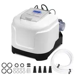
SKU: 90145POOL CLEAR SALTWATER SYSTEM
E.C.O. (Electrocatalytic Oxidation) for up to 15,000-Gallon Pools
90145
Read all safety warnings and instructions. Failure to follow the warnings and
instructions may result in electric shock, fire and/or serious injury. Save all
warnings and instructions for future reference.
INSTALLATION AND USER’S GUIDE
DANGER

THIS PAGE INTENTIONALLY LEFT BLANK

TABLE OF CONTENTS
1
TABLE OF CONTENTS
IMPORTANT SAFETY INSTRUCTIONS
OVERVIEW (PRODUCT INFORMATION)
SPECIFICATION
INSTALLATION
INSTALLATION INSTRUCTIONS
OPERATION
CONTROL PANEL
REPLACEMENT PARTS 14
Disclaimer
Legends and Symbols
DISCLAIMER 16
1
16
2
2
4
6
7
7
Customer Service and Technical Support 16
PRODUCT INTRODUCTION
5
10
TROUBLESHOOTING
13
10
TROUBLESHOOTING
13
PARTS DIAGRAM
14
PACKAGING CONTENTS
4
PARTS LIST
15
DIMENSIONS
6
CUSTOMER SERVICE
If you have any questions about ordering our pool pumps and replacement parts or pool products,
please feel free to contact us using the following contact information:
Customer Service and Technical Support
Phone: (909) 628-0880
Email: [email protected]
Hours of Operation: Monday – Friday, 9AM – 4PM (CST)

THIS PAGE INTENTIONALLY LEFT BLANK
IMPORTANT SAFETY INSTRUCTIONS
2
For safety reasons, children should not be allowed to use this product.
Packing materials and plastic bags are not toys. Keep them away from children to prevent the risk
of suffocation.
Failure to comply with all instructions and warnings may lead to severe bodily
injury or even death. For optimal safety and functionality, it is advisable to have the product installed
and serviced by a certified service professional. Prior to using this product, installers, operators, and
owners must carefully review these warnings and all instructions provided in the owner's manual. It
is essential to leave these warnings and the owner's manual with the owner for their reference and
safety.
ATTENTION INSTALLER: This manual contains vital information regarding the installation,
operation, and safe use of this product. It is essential to provide this manual to the end user of the
product. Failure to read and follow all instructions could lead to severe injuries.
USE OF NON-XTREMEPOWERUS REPLACEMENT PARTS VOIDS WARRANTY
DANGER: Ignoring these hazards can result in death, severe personal injury, or
significant property damage.
WARNING: Indicates potential hazards that can result in severe personal injury,
death, or significant property damage. Ignoring these warnings presents a real
danger.
CAUTION: Indicates potential hazards that can result in minor or moderate
personal injury, property damage, or actions that are unpredictable and unsafe.
Ignoring these cautions presents a potential hazard.
NOTICE: This label indicates important special instructions that are not directly
related to hazards.
This guide provides instructions for installing and using the Pool Clear Salt Water System. For
inquiries about the equipment, please contact XtremepowerUS.
This guide contains important information about safely installing and operating this product. After
installation, make sure to share this information with the owner/operator or leave it with them for
their reference.
Legends and Symbols
When encountering the safety-alert symbol on the equipment or within this manual, pay attention to
the following signal words and remain vigilant about the potential for personal injury.
IMPORTANT SAFETY INSTRUCTIONS
DANGER
WARNING
WARNING
CAUTION
NOTE
DANGER
3
DANGER
WARNING
CAUTION
• Storable Pools Only: Use this product with storable pools, not permanently-installed pools. The
pool must be installed no closer than 6 feet (1.8 m) from any electrical outlet, with portable
appliances kept at least 5 feet (1.5 m) away to reduce the risk of electric shock.
• Proper Installation and Use: Incorrect installation or use could lead to reduced product efficiency
and safety hazards.
NOTE
• These guidelines address common risks and do not cover all potential dangers. Always exercise
caution and use good judgment when engaging in water activities. For use with portable
above-ground pools only.
• Outdoor Use Only: This product is designed exclusively for outdoor use.
• Supervision Required: Never allow children to use this product unsupervised. Children and
those with disabilities must be closely monitored to prevent injury.
• Assembly and Disassembly: These tasks should only be performed by adults to prevent acci-
dents.
• Electric Shock Prevention: Always disconnect the product from the electrical outlet before clean-
ing, servicing, or making adjustments. Do not replace the supply cord as this could lead to elec-
tric shock; if damaged, replace the appliance. Avoid using extension cords or adapters and
ensure a properly located outlet is used.
• Risk of Electric Shock: Do not bury the electrical cord or place it where it can be damaged.
Always use a grounded type receptacle equipped with a ground-fault circuit interrupter (GFCI).
Do not use the unit with a damaged cell housing or if improperly assembled. Ensure the GFCI
functions correctly by testing it; if it fails or if it trips without the test button being pressed, discon-
tinue use and seek professional repair. Failure to comply may result in severe injury or death.
IMPORTANT SAFETY INSTRUCTIONS
PRODUCT OVERVIEW
4
OVERVIEW (PRODUCT INFORMATION)
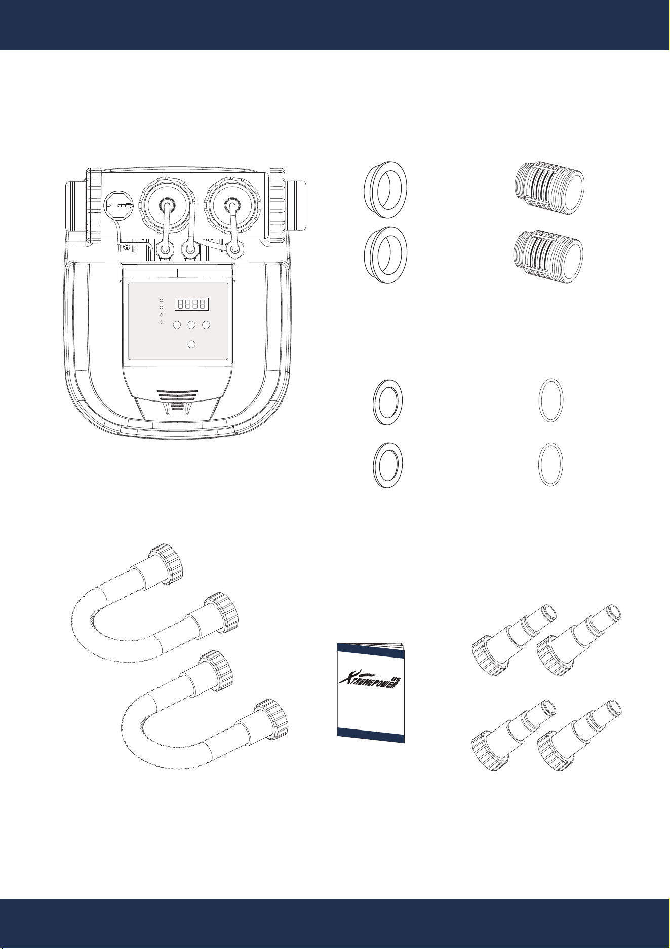
PACKAGING CONTENTS
PARTS: P90145-4
CONNECTOR
(OPTIONAL)
2 PC(S)
PARTS:
P90145-13
GASKET
(OPTIONAL)
2 PC(S)
PARTS:
P90145-2
SEALS
2 PC(S)
PARTS:
P90145-14
HOSE WITH ADAPTER
2 PC(S)
SALTWATER SYSTEM
1 PC(S)
INSTRUCTION
MANUAL
1 PC(S)
PARTS: P90145-15
CONNECTOR ASSEMBLY
(OPTIONAL)
4 PC(S)
PARTS: P90145-19
O-RING
(OPTIONAL)
2 PC(S)
GENERATING
HIGH
TIMER
SETTING POWER
BOOSTING
LOW
FLOW
5
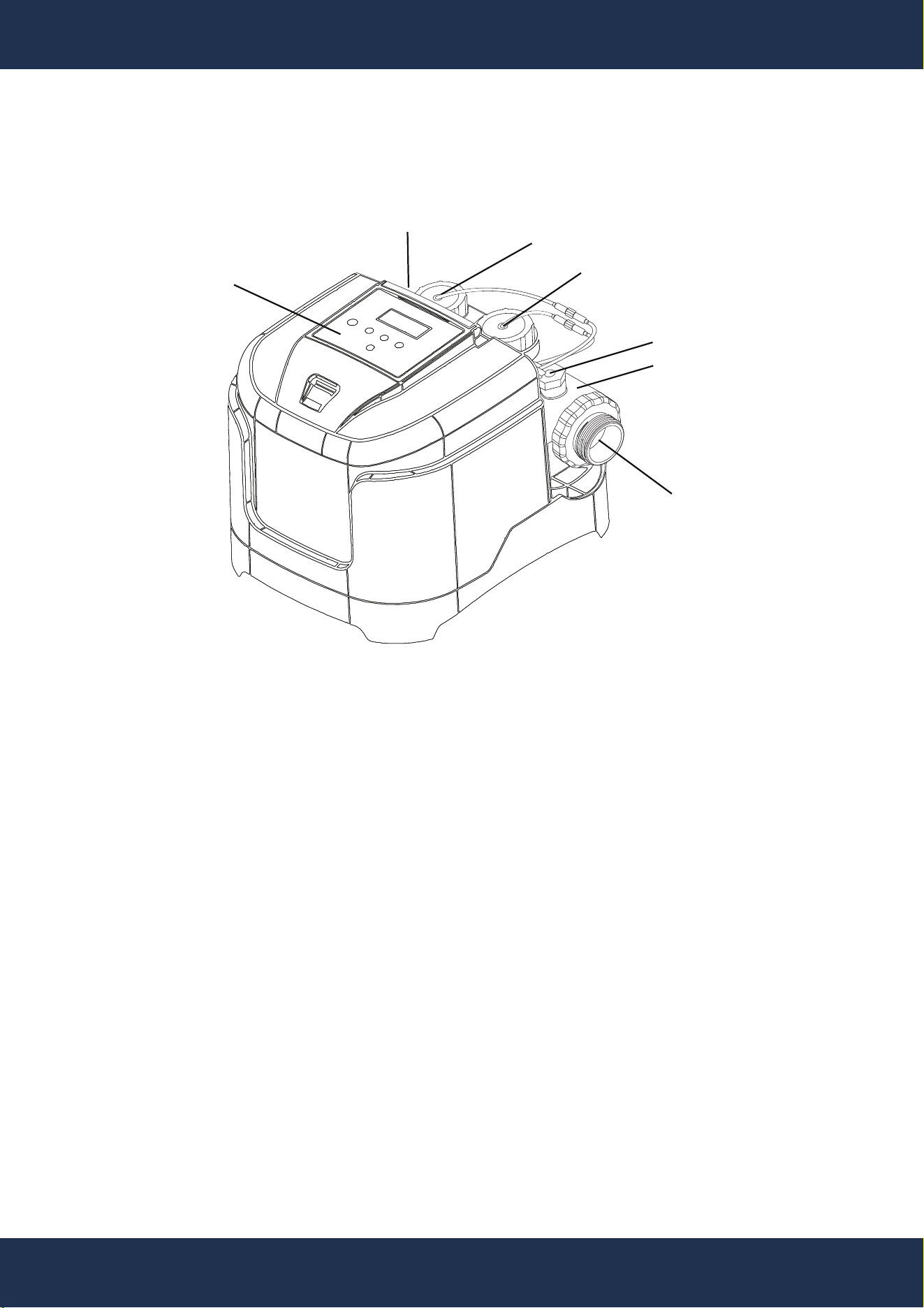
PRODUCT INTRODUCTION
PRODUCT OVERVIEW
ELECTRONIC
CONTROL PANEL
INLET
OUTLET
WATER FLOW SWITCH
ELECTROLYTIC CELL
CONTAINER
CHLORINE ION GENERATOR
COPPER ION GENERATOR
Pool Clear SaltWater System
• This product is designed for above-ground pools to provide a clean and comfortable swimming
environment by effectively treating the water.
• The system utilizes common salt (sodium chloride), composed of sodium and chloride
elements. During the initial setup, a precise amount of salt is dissolved in the pool water,
creating a mildly salty solution. As pool water circulates through the Saltwater System’s
electrolytic cell, chlorine is produced. This chlorine immediately begins working to neutralize
bacteria and break down organic matter from swimmers.
E.C.O. (Electrocatalytic Oxidation)
• Electrocatalytic Oxidation, a component of Advanced Oxidation Processes (AOPs), is initiated
when a direct current is applied to the system’s electrodes. This generates hydroxyl radicals,
powerful agents that break down organic contaminants. The presence of hydroxyl radicals,
along with chlorine, creates an efficient and secure method for purifying pool water.
6
PRODUCT OVERVIEW
SPECIFICATION
TECHNOLOGY
SUITABLE POOL TYPE
SUITABLE POOL CAPACITY
INPUT VOLTAGE
OUTPUT VOLTAGE
ELECTRIC CURRENT
POWER CONSUMPTION
MAXIMUM CHLORINE OUTPUT
POWER CORD
MAINTENANCE
SELF-CLEANING
FUNCTION
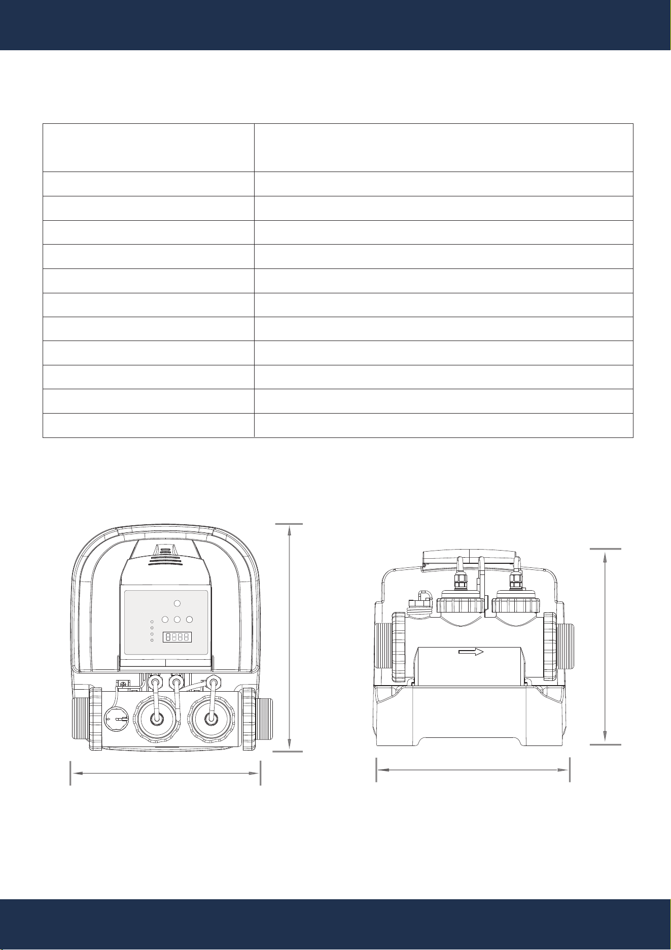
DIMENSIONS
11”
13”
10”
GENERATING
HIGH
TIMER
SETTING POWER
BOOSTING
LOW
FLOW
11”
E.C.O (ELECTROCATALYTIC OXIDATION)
0-0.5 PARTS PER MILLION (PPM); REPLACE IF GAP > 0.39”
ABOVE-GROUND POOLS
UP TO 15,000 GALLONS
115V / 230V (DUAL VOLTAGE CAPABILTY)
ASV
0.5A / 0.25A
60W
0.18OZ / HR
6FT
EVERY 3MONTHS
EVERY 2HRS
WATER FLOW SENSING

7
INSTALLATION
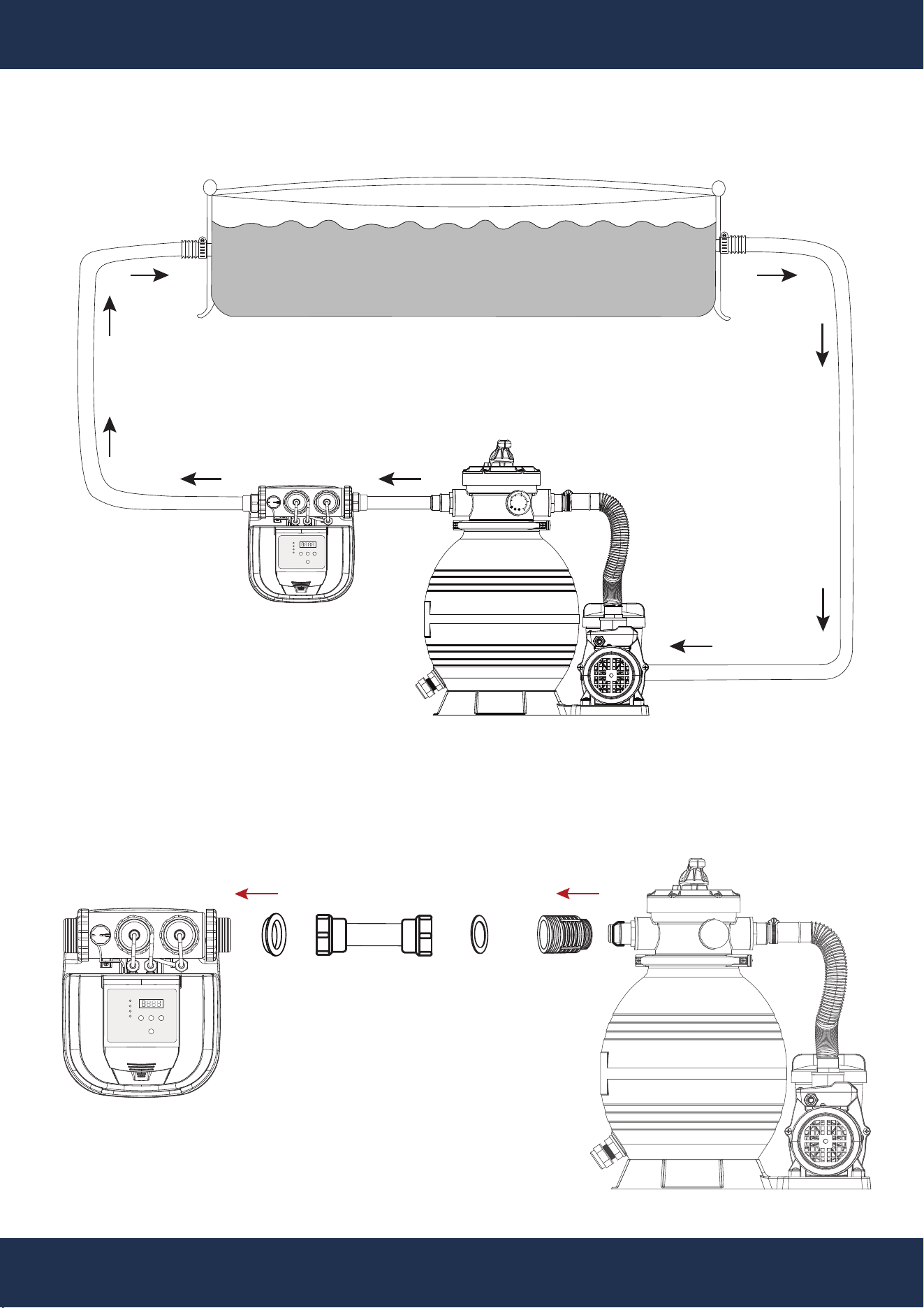
INSTALLATION INSTRUCTIONS
INSTALLATION
NOTE
• Install the Saltwater System as the final component in the water return line to the pool to protect
the titanium plates.
• Ensure a separate filter pump with a flow rate between 700 to 3000 GPH (2650 to 11,355 LPH)
for effective operation.
• Pool Preparation: Assemble a new pool and filter pump, or shut off the existing setup.
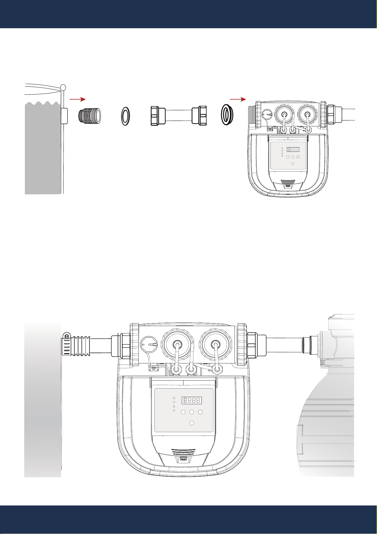
• Positioning: Position the Saltwater System downstream of the pump and filter (see Figure A).
• Connections: Connect the system inlet to the pump outlet using appropriate hoses and
adapters, depending on the pump and pool connections (see Figure B).
• Secure Connections: Tighten all connections securely to prevent leaks.
• Testing: Test the system to ensure proper function before regular use.
POOL PUMP AND SAND FILTER
(NOT INCLUDED)
POOL CLEAR
SALTWATER
SYSTEM
8
INSTALLATION
PARTS: 2
PARTS: 12
PARTS: 13
PARTS: 14
Figure B Water Intake Hose Connection
PUMP OUTLET
PORT
SALTWATER SYSTEM
INLET PORT
POOL PUMP AND SAND FILTER
(NOT INCLUDED)
GENERATING
HIGH
TIMER
SETTING POWER
BOOSTING
LOW
FLOW
GENERATING
HIGH
TIMER
SETTING POWER
BOOSTING
LOW
FLOW
Figure A Above-Ground Swimming Pool Equipment Layout
ABOVE-GROUND POOL WITH SALTWATER
POOL CLEAR
SALTWATER
SYSTEM
POOL
INLET PORT
POOL
OUTLET PORT
psi
bar
KL1.6
1
0
10
20
30
50
60
2
3
4
40
9
INSTALLATION
Figure D Water Hose Connection Completed
ABOVE-GROUND POOL
WITH SALTWATER
(NOT INCLUDED)
Figure C Water Return Hose Connection
PARTS: 12
PARTS: 13 PARTS: 14
POOL CLEAR
SALTWATER
SYSTEM
SALTWATER SYSTEM
OUTLET PORT
ABOVE-GROUND POOL
INLET PORT
ABOVE
GROUND
POOL
POOL
PUMP
GENERATING
HIGH
TIMER
SETTING POWER
BOOSTING
LOW
FLOW
PARTS: 2
GENERATING
HIGH
TIMER
SETTING POWER
BOOSTING
LOW
FLOW
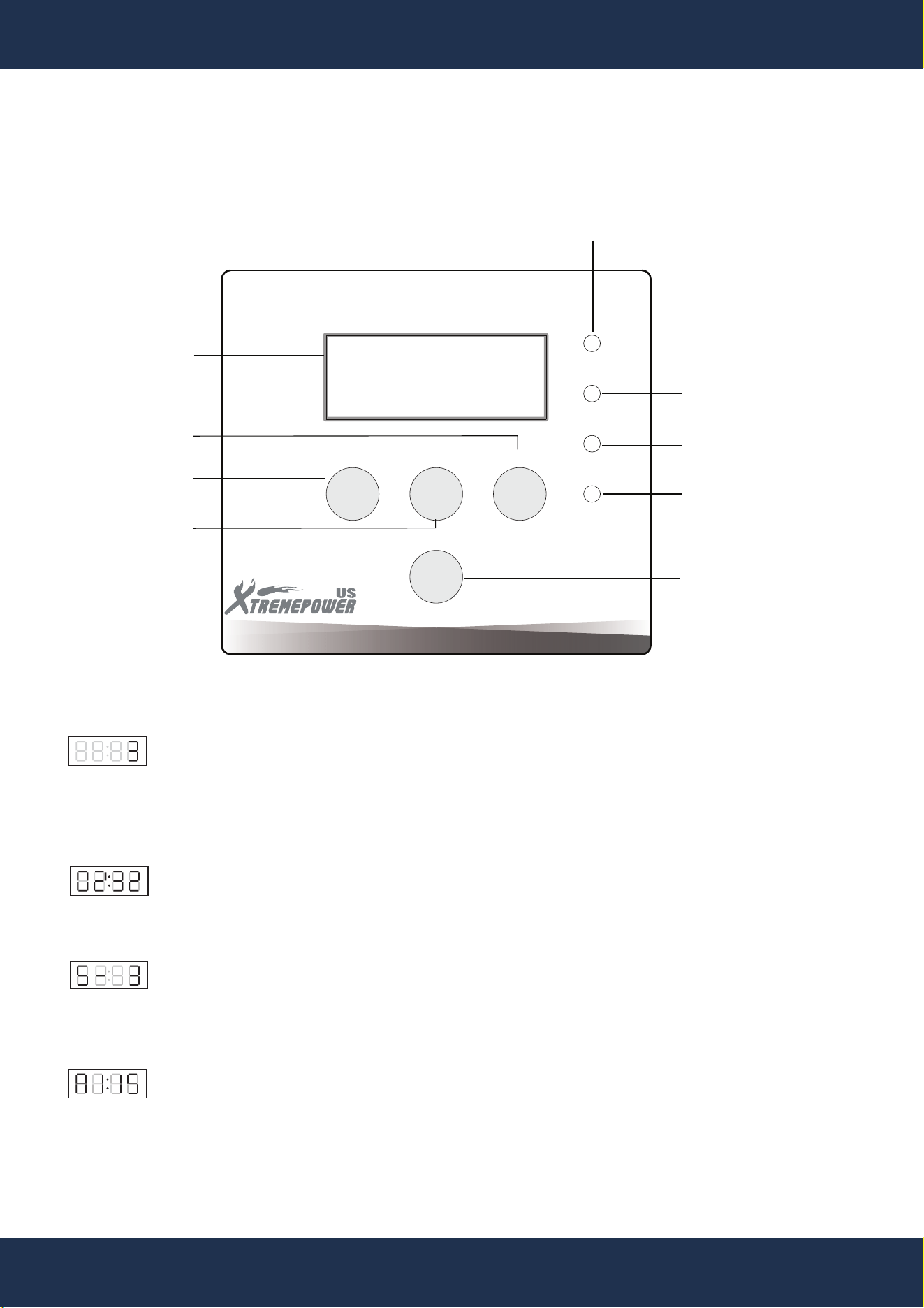
Display Guide
Daily Operation Time:
Set by powering on or pressing SETTING. Displays as a daily cycle (e.g., "3" for 3 hours per day
from startup). Adjust according to pool size; see section “Pool Size and Recommended Operation
Time.”
Remaining Cycle Time:
Displays the time left in the current cycle (e.g., "02:32" for 2 hours and 32 minutes remaining).
Super Chlorination Mode (S):
Enhanced chlorination mode, where the "-3" setting increases the normal chlorination duration to
24 times (3 multiplied by 8) the standard rate.
Electrolysis Current (A1:15):
Indicates the current flow for chlorination, typically yielding 2.6 times the chlorination rate relative
to the current shown.
10
OPERATION
CONTROL PANEL
Interface Overview
OPERATION
GENERATING
FLOW
TIMER SETTING
BOOST
POWER
LOW
HIGH
DISPLAY
TIMER SETTINGS
(1-12 HOURS)
CONFIGURATION
INTERFACE
POWER SWITCH
SUPER CHLORINATION
MODE
HIGH SALT WARNING
OPERATIONAL INDICATORS
▪ RED: SHUTDOWN
▪ BLUE: IN OPERATION
▪ GREEN: STANDBY MODE
LOW SALT WARNING
WATER FLOW WARNING

11
Function Description
Setting Mode:
• Activate: Long press SETTING until display blinks.
• Adjust: Use TIME to set duration based on pool size.
Chlorine Production Mode:
• Start: Press POWER after setting the time.
• Indicators: Blue light during operation, green light in hibernation.
• Resume: Automatically restarts at the same time the next day.
Super Chlorine Mode:
• Activate: Press BOOST during normal operation for 8x extended chlorination.
• Note: Ensure the pump and filtration system are active.
Self-Cleaning Mode:
• Automatic: Cleans every 2 hours with no user input required.
Power-Off Memory:
• Resume: Automatically continues with previous settings after power loss.
Water Flow Sensing:
• Monitor: Halts operation if no water is detected, then resumes without resetting the timer
once flow is restored.
Query Mode:
• Access: Long press TIME to view current settings. Press again to display the countdown. Exit
with SETTING.
ECO Copper Ion Generator:
• Maintenance: Regularly check copper ion concentration (0-0.5 mg/L) and gap size. Replace
the generator if the gap exceeds approximately 0.4 inches.
OPERATION
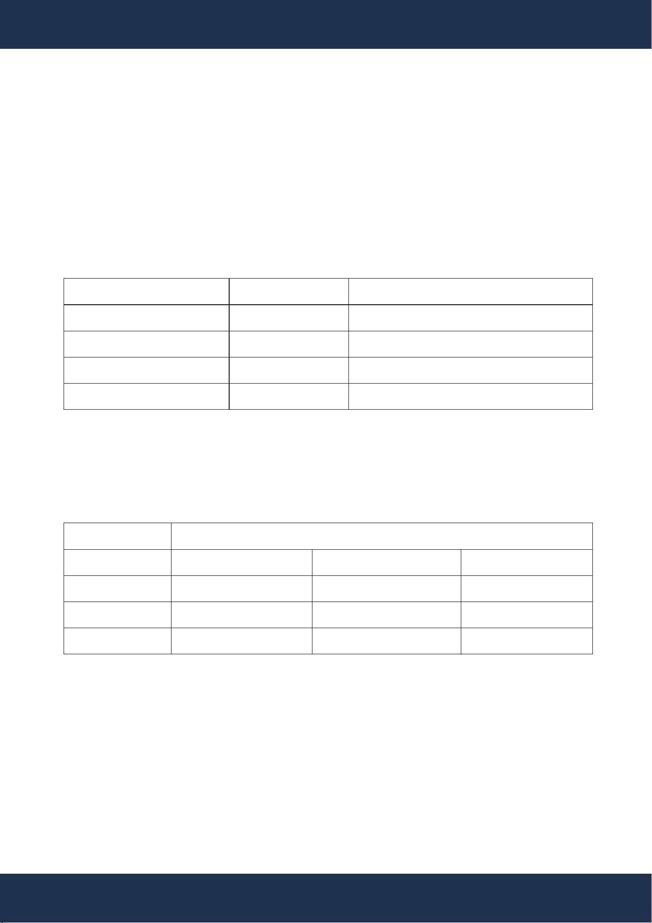
RECOMMENDED OPERATING TIME BASED ON ENVIRONMENTAL CONDITION
68°F - 82°F
3 HOURS
5 HOURS
7 HOURS
12
Salt Concentration and Pool Settings
Salt Range:
• Optimal Concentration: 2500-3500 PPM, ideal at 3000 PPM.
• Device Operational Range: 700-4000 PPM.
• Low Salt Risks: Reduces system efficiency and chlorine production.
• High Salt Risks: Can make water salty, damage power supply, and corrode metal fixtures.
Salt loss only occurs with water removal, not evaporation.
• Required Salt for Pools:
OPERATION
POOL VOLUME
GALLON
2000
4000
6000
INITIAL SALT
LBS
50
100
150
ADD SALT ON LOW SALT ALARM
LBS
10
25
40
Copper Ion Concentration
• Range: 0-0.5 mg/L. Confirm with copper ion test strips
POOL VOLUME
GALLON
2000
4000
6000
50°F - 66°F
2 HOURS
4 HOURS
6 HOURS
84°F - 97°F
4 HOURS
6 HOURS
8 HOURS
Pool Size and Recommended Operation Time

13
TROUBLESHOOTING
TROUBLESHOOTING
Salt Concentration and Pool Settings
Water Flow Protection: FLOW Red Light
▪ Cause: Pump stopped or valves closed
▪ Solution: Start the circulation pump, check for blockages, and open valves.
▪ Cause: Faulty flow switch or loose connections
▪ Solution: Replace the flow switch if the pump is on and the switch is closed.
High Salt Alert: HIGH Blue Light, GENERATING Bright Blue
▪ Cause: Excessive salt concentration
▪ Solution: Dilute by partially draining and refilling with fresh water.
Overcurrent Protection: HIGH Red Light, GENERATING Bright Green
▪ Cause: High salt concentration or generator blockage
▪ Solution: Clean the generator, check the salt level, and restart the system.
Low Salt Alert: LOW Blue Light
▪ Cause: Salt level below 700 PPM
▪ Solution: Add salt to the pool.
Low Current: LOW Red Light
▪ Cause: Extremely low salt level or circuit break
▪ Solution: Check the generator and salt level. Replace the generator if necessary, especially if
it's beyond its expected lifespan.
14
REPLACEMENT PARTS
REPLACEMENT PARTS
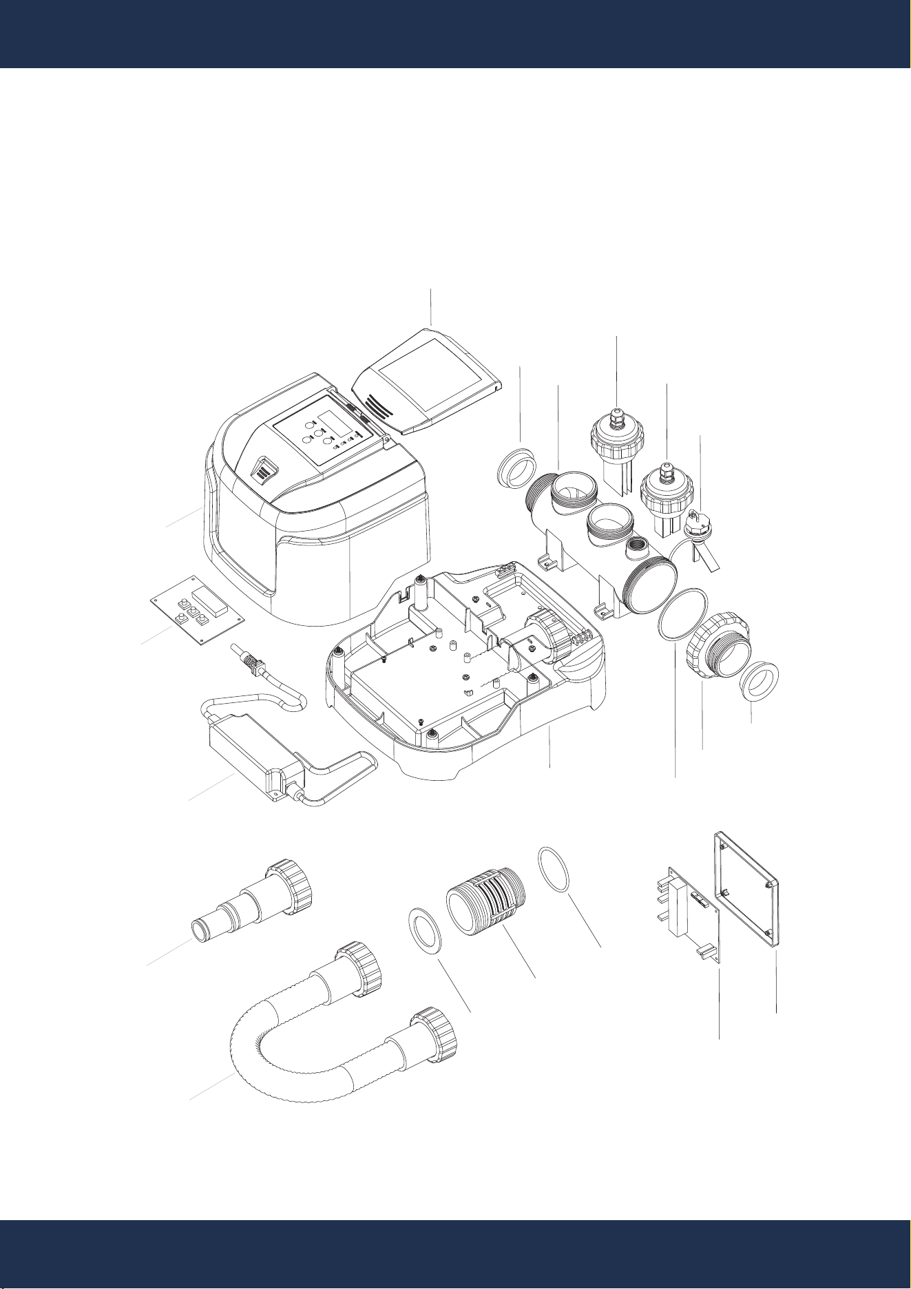
PARTS DIAGRAM
PART: 1
PART: 2
PART: 4
PART: 7
PART: 6
PART: 5
PART: 3
PART: 8
PART: 9
PART: 12
PART: 13
PART: 18
PART: 17
PART: 16
PART: 15
PART: 14
PART: 19
PART: 10
PART: 11
PART: 2
15
REPLACEMENT PARTS
REPLACEMENT PARTS
ITEM
90145-1
90145-2
90145-3
90145-4
90145-5
90145-6
90145-7
90145-8
90145-9
90145-10
90145-11
90145-12
90145-13
90145-14
90145-15
90145-16
90145-17
90145-18
90145-19
REFERENCE #
41025044
5432055080
647019607
647019672000
647019671000
576024000
5432098080
647019608
647019602
647019603
5028322000
647279510001
65432044080
647229003001
91120001
5760224000
502832100
647019601
5431021080
DESCRIPTION
CONTROL BOX COVER
SEALS 56* 47*14MM
ELECTROLYTIC CELL CONTAINER
CHLORINE ION GENERATOR
COPPER ION GENERATOR
WATER FLOW SWITCH
GASKET 78* 7*2.5MM
CONTAINER CAP
BASE
CONTROL PLATE BRACKET
CIRCUIT BOARD
CONNECTOR
GASKET 54.8* 36.8*2.4MM
1 1/2”x 5.4FT HOSE WITH ADAPTER
CONNECTOR ASSEMBLY
AC/DC ADAPTER
WIRING HARNESS BOARD
CONTROL PANEL COVER
O-RING 44.04* 3.53MM
QTY
1
2
1
1
1
1
1
1
1
1
1
2
2
2
4
1
1
1
2
PARTS LIST
o o
o o
o
o

16
REPLACEMENT PARTS
DISCLAIMER
PLEASE READ THE FOLLOWING CAREFULLY
The manufacturer and/or distributor have provided the parts list and assembly diagram in this
manual for reference purposes only. They do not make any representation or warranty to the buyer
that they are qualified to make repairs to the product or replace any parts of the product. In fact, the
manufacturer and/or distributor expressly state that all repairs and parts replacements should be
undertaken by certified and licensed technicians, and not by the buyer.
The buyer assumes all risk and liability arising from their repairs to the original product or
replacement parts or arising from their installation of replacement parts. It is strongly advised that
qualified professionals handle any repairs or replacements to ensure safety and proper functioning
of the product. Improper installation and operation may result in injury, property damage, or voiding
of warranty. The manufacturer and/or distributor shall not be held responsible for any accidents,
damages, or malfunctions resulting from the buyer's installation and operation of the product. It is
essential to follow all safety guidelines and recommendations provided in this manual and to seek
professional assistance if unsure about the installation or operation procedures.
CUSTOMER SERVICE
If you have any questions about ordering our pool pumps and replacement parts or pool products,
please feel free to contact us using the following contact information:
Customer Service and Technical Support
Phone: (909) 628-0880
Email: [email protected]
Hours of Operation: Monday – Friday, 9AM – 4PM (CST)
