ASSEMBLY AND USER’S GUIDE
Read all safety warnings and instructions. Failure to follow the warnings and instructions may result in serious
injury. Save all warnings and instructions for future reference.
SKU: 75220
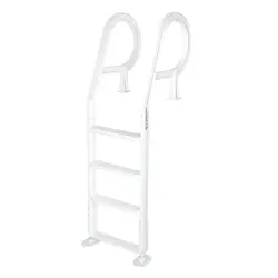
ABOVE GROUND POOL
ADJUSTABLE DECK LADDER
75220
IMPORTANT:


TABLE OF CONTENTS
1
TABLE OF CONTENTS
IMPORTANT SAFETY INSTRUCTIONS
OVERVIEW (PRODUCT INFORMATION)
SPECIFICATION
ASSEMBLY
STEP 1
STEP 2
STEP 3
LEGENDS AND SYMBOLS
1
2
2
4
4
6
5
5
PACKAGING CONTENTS
6
6
DIMENSIONS
6
DISCLAINMER
DISCLAIMER 9
9
CUSTOMER SERVICE AND TECHNICAL SUPPORT
9
REPLACEMENT PARTS 8
STEP 4
STEP 5
7
7
IMPORTANT SAFETY INSTRUCTIONS
2
ATTENTION INSTALLER: This manual contains vital information regarding the installation,
operation, and safe use of this product. It is essential to provide this manual to the end user of the
product. Failure to read and follow all instructions could lead to severe injuries.
USE OF NON-XTREMEPOWERUS REPLACEMENT PARTS VOIDS WARRANTY
DANGER: Ignoring these hazards can result in death, severe personal injury, or
significant property damage.
WARNING: Indicates potential hazards that can result in severe personal injury,
death, or significant property damage. Ignoring these warnings presents a real
danger.
CAUTION: Indicates potential hazards that can result in minor or moderate
personal injury, property damage, or actions that are unpredictable and unsafe.
Ignoring these cautions presents a potential hazard.
NOTICE: This label indicates important special instructions that are not directly
related to hazards.
This guide provides instructions for installing and using the Above Ground Pool Adjustable Deck
Ladder. If you have any questions about the equipment, please contact XtremepowerUS.
This guide contains important information about safely installing and operating this product. After
installation, make sure to share this information with the owner/operator or leave it with them for
their reference.
Legends and Symbols
When you come across the safety-alert symbol on your equipment or in this manual, pay attention
to the following signal words and remain vigilant about the potential for personal injury.
IMPORTANT SAFETY INSTRUCTIONS
DANGER
WARNING
CAUTION
NOTE
DANGER
• NO JUMPING
• NO DIVING
WARNING
• The gap between the pool's inner wall and the ladder must not exceed 4” to prevent entrapment.
If the gap is over 4”, install the safety kit to prevent drowning.

IMPORTANT SAFETY INSTRUCTIONS
3
CAUTION
NOTE
• Prevent ladder damage and minimize injury risk by following these careful instructions.
• Install the ladder on a solid base.
• For pool ENTRY / EXIT, face the pool at all times.
• This ladder is only for entering and exiting the pool. Using it for any other purpose may damage
the ladder and pool structure.
• To prevent entrapment or drowning, do not swim through, behind, or around the ladder.
• Maximum weight limit: 225 LBS.
• This ladder is intended for use with above-ground pools measuring 48”, 52”, or 54” in height.
• For winter, remove the ladder from the pool and store it in a dry place.
OVERVIEW (PRODUCT INFORMATION)
4
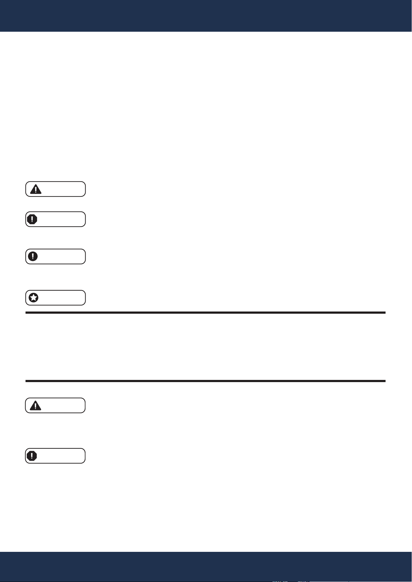
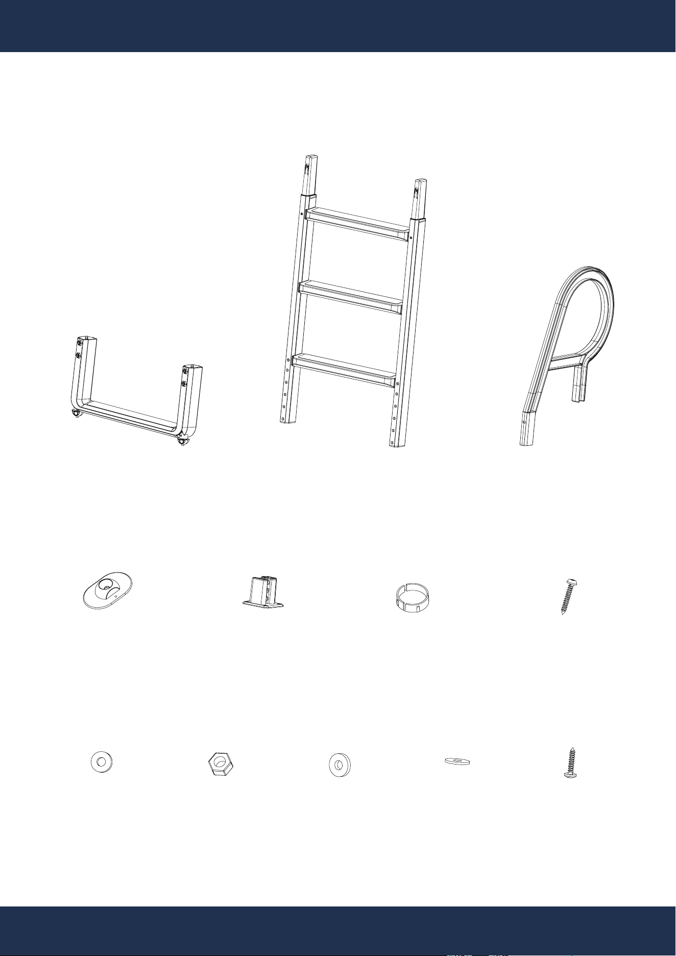
PACKAGE CONTENTS
OVERVIEW (PRODUCT INFORMATION)
PARTS#: 1
1 PC(S)
PARTS#: 2
1 PC(S)
PARTS#: 3
2 PC(S)
PARTS#:
4
2 PC(S)
PARTS#: 5
2 PC(S)
PARTS#: 6
2 PC(S)
PARTS#: 7 a
4 PC(S)
PARTS#:
7 b
4 PC(S)
PARTS#: 7 c
2 PC(S)
PARTS#: 7 d
2 PC(S)
PARTS#: 7 g
12 PC(S)
PARTS#: 7 f
12 PC(S)
28.9”
OVERVIEW (PRODUCT INFORMATION)
5
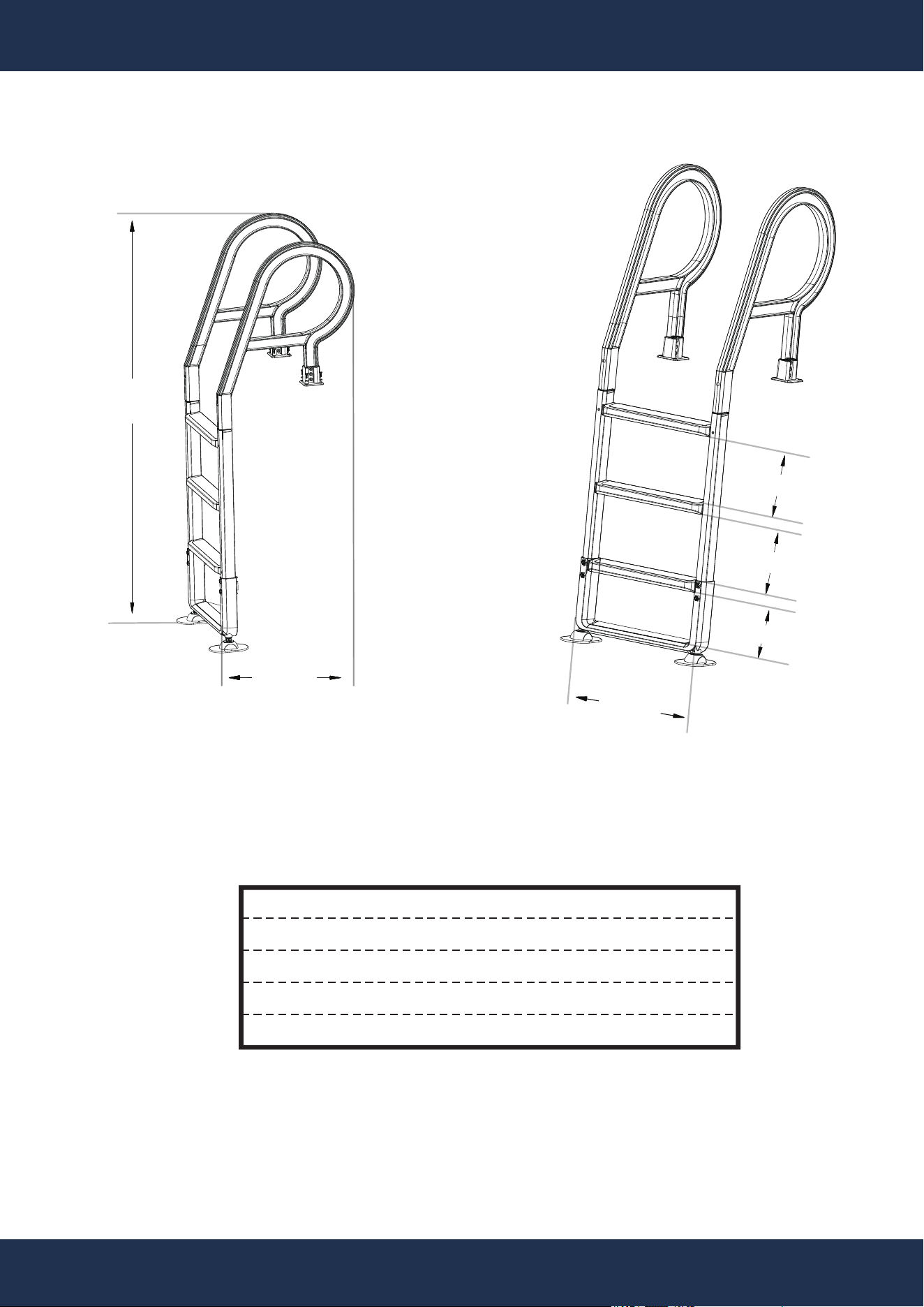
DIMENSIONS
75.4”
28.9”
26.6”
10.0”
10.0”
9.7”
SPECIFICATIONS
MODEL
MATERIAL
PRODUCT WEIGHT
DIMENSIONS
ADJUSTABLE HEIGHT
75220
PP
23.57 LBS
26.6” x 75.4” x 28.9”
48” / 52” / 54”
ASSEMBLY
6
ASSEMBLY INSTRUCTIONS
AJUSTABLE
HEIGHT:
48”
52”
54”
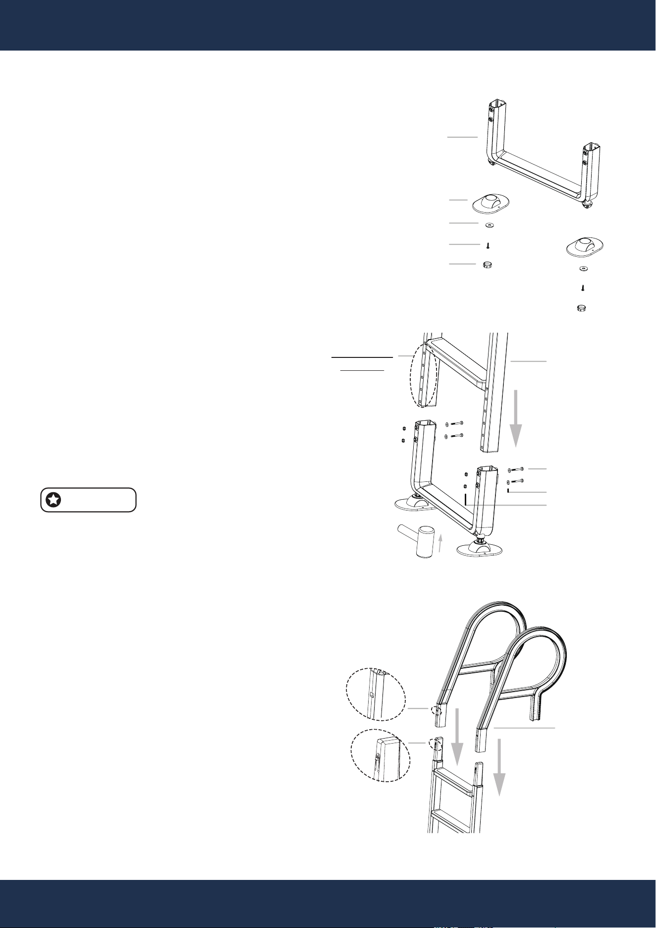
STEP 1
• Assemble the base by attaching
two feet PARTS# 4 to a "U" shaped
ladder base PARTS# 1 using one
stainless steel screw PARTS# 5,
washer PARTS# 6, and plastic cap
PARTS# 7 per foot. See FIGURE A.
PARTS#: 1
PARTS#: 4
PARTS#: 5
PARTS#: 6
PARTS#: 7
FIGURE A
FIGURE B
FIGURE C
STEP 2
• Insert the ladder frame PARTS# 2
into the base assembly FIGURE A.
Match the ladder frame PARTS# 2
plus base FIGURE A to the pool
height—48”, 52”, or 54”. Secure by
inserting four bolts PARTS# 8
through pre-drilled holes and tighten
with washers PARTS# 9 and nuts
PARTS# 10. See FIGURE B.
• A mallet or similar tool may be used
for a more compact fit during
installation.
NOTE
STEP 3
• Alignment is key. If necessary,
adjust with appropriate tools.
• Place the handrail PARTS# 3 into
the assembled ladder FIGURE B.
See FIGURE C.
PARTS#: 2
PARTS#: 8
PARTS#: 9
PARTS#: 10
PARTS#: 3
ASSEMBLY
7
ASSEMBLY INSTRUCTIONS (CONTINUED)
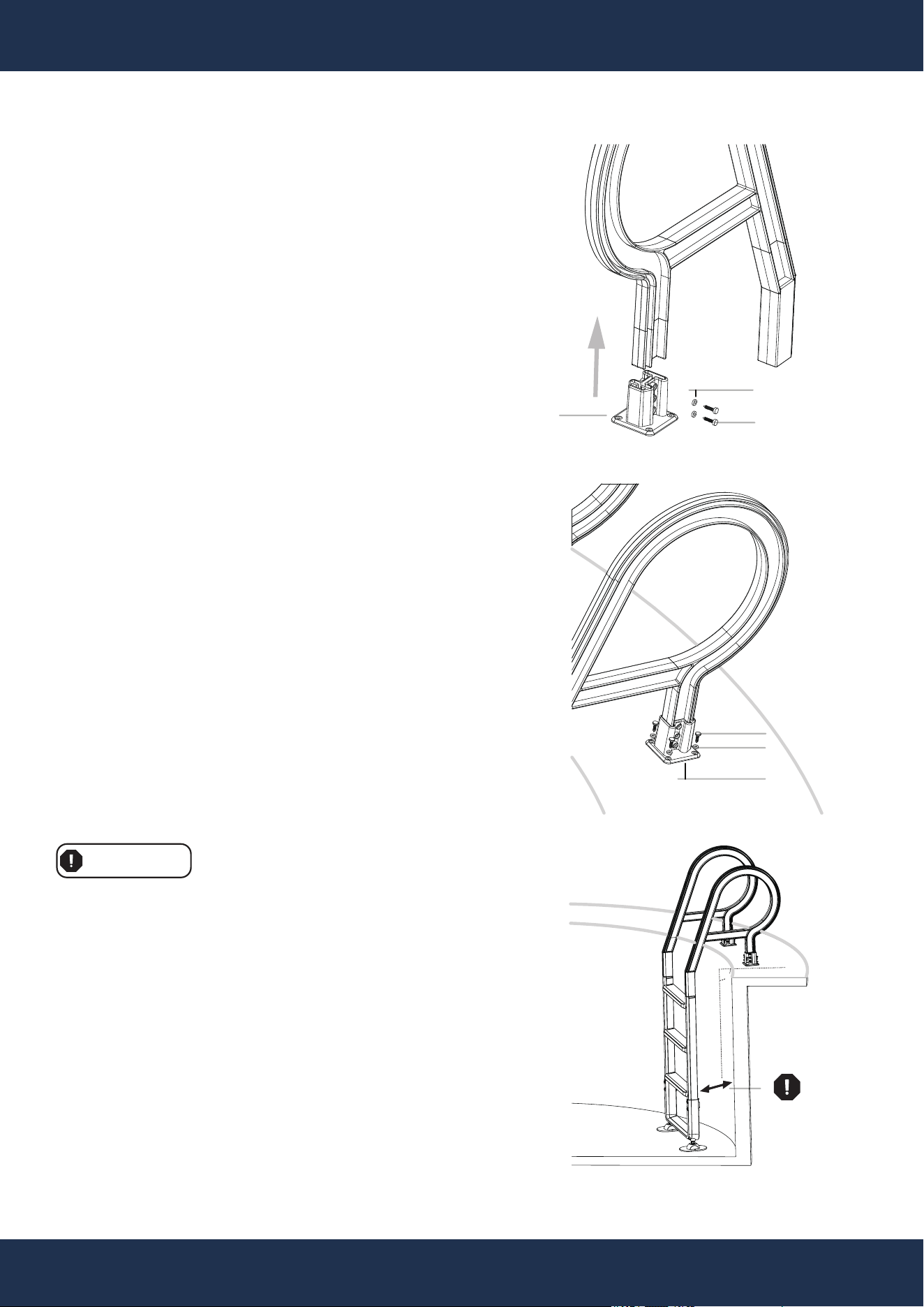
STEP 4
• Fit the bases PARTS# 11 to the
ends of the handrails and secure
with the provided screws PARTS#
12 and washers PARTS# 13. Adjust
the height as needed. See FIGURE
D.
FIGURE D
4” Max.
FIGURE E
STEP 5
• Firmly secure the bases PARTS#
11 to the platform, using the
washers PARTS# 13 and screws
PARTS# 12. See FIGURE E.
WARNING
• Maintain a space of 4” or less
between the pool's inner wall and
the ladder to avoid the risk of
becoming trapped.
• This ladder is designed solely for
getting into and out of the pool.
Misuse could cause damage to
both the ladder and the pool's
structure.
• A gap exceeding 4 inches
necessitates the installation of a
safety kit to prevent the risk of
accidental drowning.
PARTS#: 11
PARTS#: 13
PARTS#: 12
PARTS#: 12
PARTS#: 13
PARTS#: 11
90°
REPLACEMENT PARTS
8
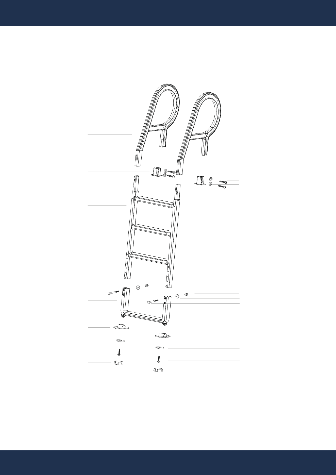
PARTS DIAGRAM
REPLACEMENT PARTS
PARTS#: 1
PARTS#: 2
PARTS#: 3
PARTS#: 4
PARTS#: 6
PARTS#: 7 a
PARTS#: 5
PARTS#: 7 c
PARTS#: 7 b
PARTS#: 7 d
PARTS#: 7 e
PARTS#: 7 f
PARTS#: 7 g
PARTS #
1
2
3
4
5
6
7
REFER. #
47153901001
47153902001
647153971000
47153906001
47153905001
47153907001
65862082000
7 a
7 b
7 c
7 d
7 e
7 f
7 g
DESCRIPTION
HANDRAIL
PEDAL BRACKET
TELESCOPIC SUPPORT ASSEMBLY
BASE
HANDRAIL MOUNT
SCREW CAP
HARDWARE PACK
SCREW ST4.2*25-C-H
WASHER M5
NUT M6
GASKET Φ6*Φ16*1
BOLTS M6*75
GASKETS Φ6*Φ25*1.5
SCREWS ST5.5*25-C-H
QUANTITY
2
1
1
2
2
2
1
12
12
4
4
4
2
2
REPLACEMENT PARTS
8
PARTS LIST

DISCLAIMER
9
DISCLAIMER
PLEASE READ THE FOLLOWING CAREFULLY
The manufacturer and/or distributor have provided the parts list and assembly diagram in this
manual for reference purposes only. They do not make any representation or warranty to the buyer
that they are qualified to make repairs to the product or replace any parts of the product. In fact, the
manufacturer and/or distributor expressly state that all repairs and parts replacements should be
undertaken by certified and licensed technicians, and not by the buyer.
The buyer assumes all risk and liability arising from their repairs to the original product or
replacement parts or arising from their installation of replacement parts. It is strongly advised that
qualified professionals handle any repairs or replacements to ensure safety and proper functioning
of the product. Improper installation and operation may result in injury, property damage, or voiding
of warranty. The manufacturer and/or distributor shall not be held responsible for any accidents,
damages, or malfunctions resulting from the buyer's installation and operation of the product. It is
essential to follow all safety guidelines and recommendations provided in this manual and to seek
professional assistance if unsure about the installation or operation procedures.
CUSTOMER SERVICE
If you have any questions about ordering our pool pumps and replacement parts or pool products,
please feel free to contact us using the following contact information:
Customer Service and Technical Support
Phone: (909) 628-0880
Email: [email protected]
Hours of Operation: Monday – Friday, 9AM – 4PM (CST)
