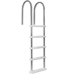
OWNER’S MANUAL AND SAFETY INSTRUCTIONS
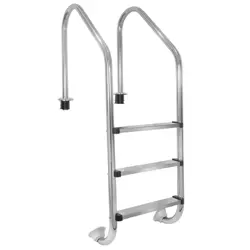
3-STEP STAINLESS STEEL POOL LADDER
ITEM # 75168
SAVE THIS MANUAL. KEEP THIS MANUAL FOR SAFETY WARNINGS, PRECAUTIONS, ASSEMBLY,
OPERATION, INSPECTION, MAINTENANCE AND CLEANING PROCEDURES. WRITE THE PRODUCT’S
SERIAL NUMBER ON THE BACK OF THE MANUAL, OR THE MONTH AND YEAR OF PURCHASE IF
PRODUCT HAS NO SERIAL NUMBER
FOR QUESTIONS, PLEASE CALL CUSTOMER SERVICE: 909.628.0880
8
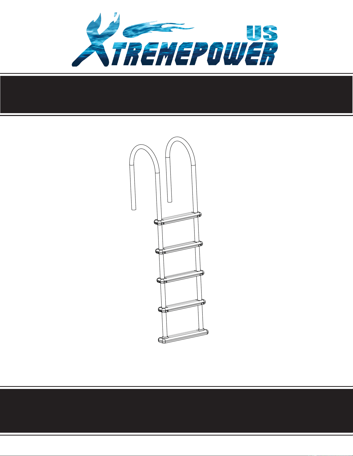
Quantity 8 Each
QUANTITY PART # DESCRIPTION
2 STAINLESS STEEL HAND RAIL
4 LADDER STEPS
2 PIVOT BALLS FOR BASE STEP
1 BOTTOM STEP
1 HARDWARE BAG
PARTS LIST
Upon opening the box and check parts against parts list below.
647154602
647154601
65320017391
648850701
88507004
65320017391
647154602
648850701
647154601
88507004
1
1
2
3
4
5
NO.
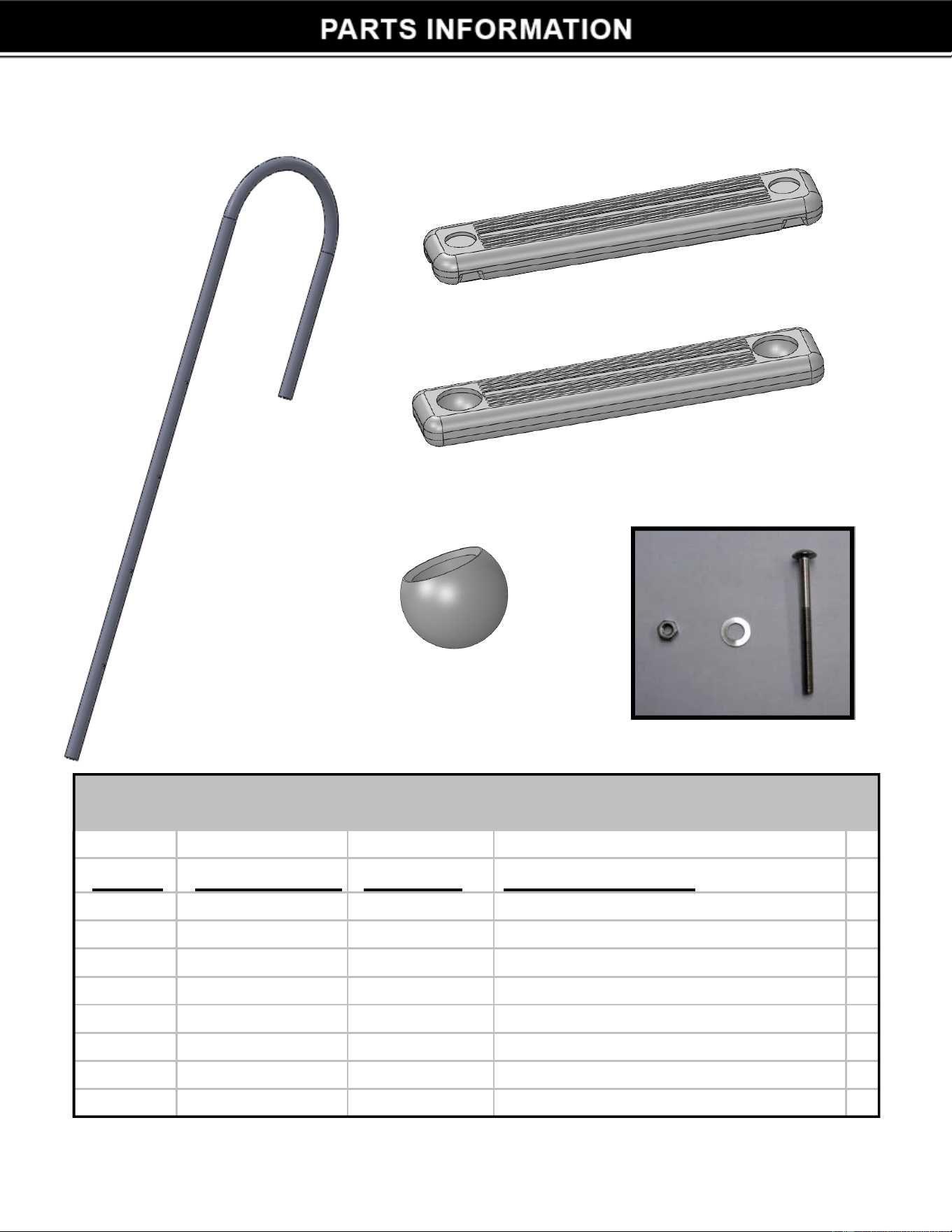
STEP 1
• S
lide 1 of the 4 ladder steps onto one of the stainless
s
t
eel handrails. See figure 1
• Make sure that the step treads are facing up.
• If you have any difficulty sliding the step onto the
handrail apply a small amount of oil to the hand-rail.
• Align the holes in the step with the top set of holes on
the handrail.
• Secure step to handrail with a bolt and nut. Make sure
that the head of the bolt is located on the outside of the
step.
See figure 2
• Slide the
second handrail through the hole on the opposite side of the step. Secure
with a nut and bolt. See figure 2
• Slide the remaining 3 steps onto the handrails and secure them with nuts and
bolts. See figure 3
F
igure 1
Figure 3
Figure 2
2
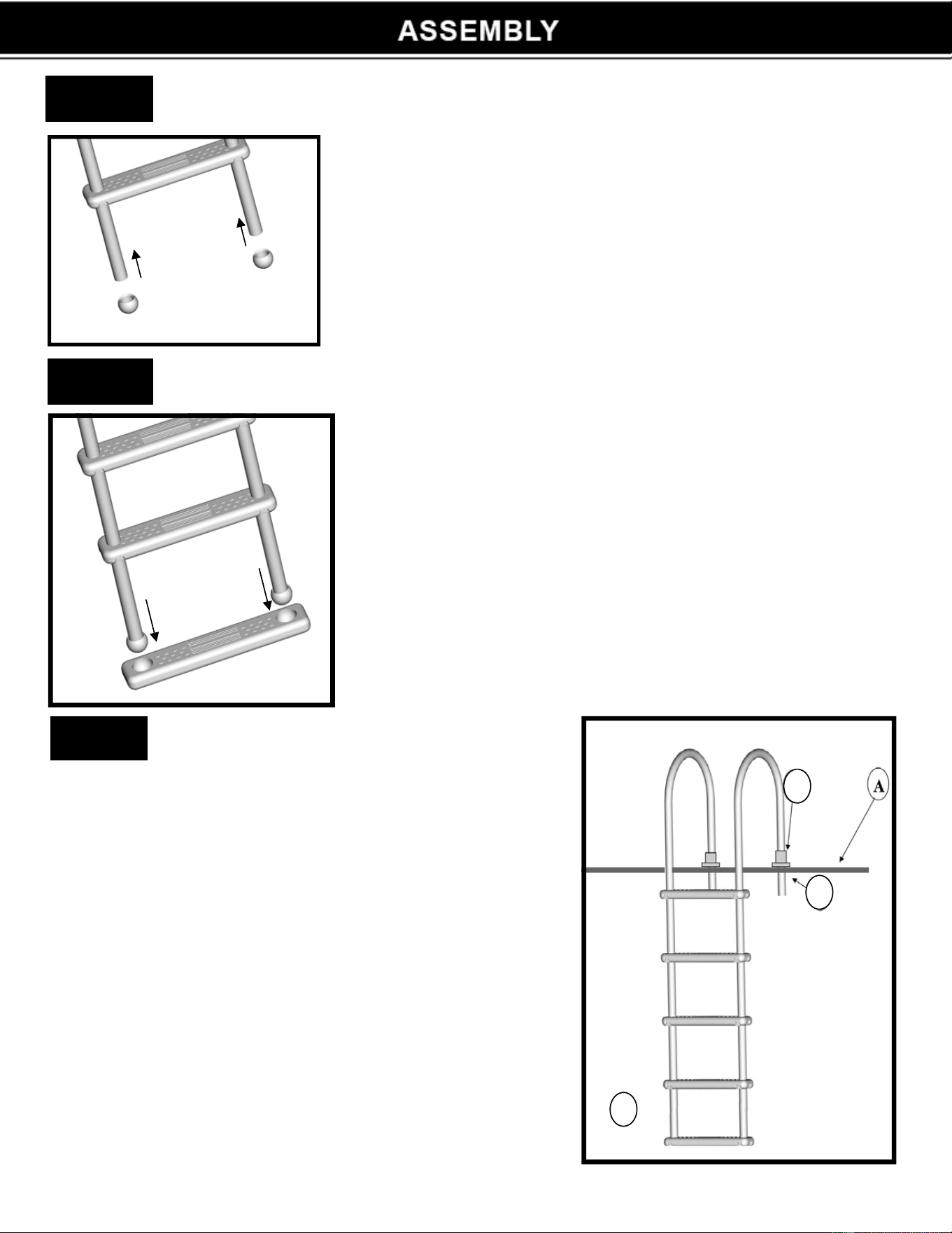
STEP 4
Figure 4
• Slide 1 pivot ball onto the bottom of each handrail
• Make s
ure both pivot balls are securely fastened to
each handrail. See figure 4
Figure 5
• P
lace the bottom step on the floor facing up
• Hold the ladder assembly straight up and align the
pivot balls with the receivers on the bottom s
tep.
• Push down firmly until both balls are inserted into
the step. See figure 5
STEP 5
Figure 6
STEP 6
Ladder Placement - Figure 6
•
•
Locate ladder in desired position on deck. (A)
M
ake sure base step rests flat against the pool
floor. Swivel step if needed to align with pool floor.
(B)
• Mark location of handrails on deck with a pencil.
• Using a 1 1/2” hole saw, dr
ill 1 hole for each
hand rail through deck surface. (C)
This will ensure that the deck will now support
the ladder.
• Secure hand rails to deck using deck flanges
(D) (flanges sold separately)
Slide flanges over each hand rail, insert
handr
ails through the holes in the deck. Secure
flanges to deck with screws. Secur
e flange to
handrail using set screw.
B
C
D
3

DISCLAIMER
4
PLEASE READ THE FOLLOWING CAREFULLY
THE MANUFACTURER AND/OR DISTRIBUTOR HAS PROVIDED THE PARTS LIST AND ASSEMBLY
DIAGRAM IN THIS MANUAL AS A REFERENCE TOOL ONLY. NEITHER THE MANUFACTURER OR
DISTRIBUTOR MAKES ANY REPRESENTATION OR WARRANTY OF ANY KIND TO THE BUYER THAT HE
OR SHE IS QUALIFIED TO MAKE ANY REPAIRS TO THE PRODUCT, OR THAT HE OR SHE IS QUALIFIED
TO REPLACE ANY PARTS OF THE PRODUCT. IN FACT, THE MANUFACTURER AND/OR DISTRIBUTOR
EXPRESSLY STATES THAT ALL REPAIRS AND PARTS REPLACEMENTS SHOULD BE UNDERTAKEN
BY CERTIFIED AND LICENSED TECHNICIANS, AND NOT BY THE BUYER. THE BUYER ASSUMES
ALL RISK AND LIABILITY ARISING OUT OF HIS OR HER REPAIRS TO THE ORIGINAL PRODUCT OR
REPLACEMENT PARTS THERETO, OR ARISING OUT OF HIS OR HER INSTALLATION OF REPLACEMENT
PARTS THERETO.
Record Product’s Serial Number Here:
Note: If product has no serial number, record month and year of purchase instead.
Note: Some parts are listed and shown for illustration purposes only and are not available
individually as replacement parts.
MADE IN CHINA