
M3 User Guide PN: MANL-M3-01-00 v.3.1
SennosM3 USER GUIDE
Intelligent Fermentation Monitoring System
Model: SENSTK-M3-01
Updated: September 3, 2026
Document PN: MANL-M3-01-00
Version: 3.1

2 | P age
TABLE OF CONTENTS
1 Before You Begin: Setup Overview ............................................................................................................ 4
2 Introduction .................................................................................................................................................. 5
2.1 About the SennosM3 System .............................................................................................................. 5
2.2 System Architecture Overview ............................................................................................................ 6
2.3 About This Guide ................................................................................................................................. 6
2.4 Intended Use & Operating Environment .............................................................................................. 7
2.5 Intended Audience ............................................................................................................................... 7
2.6 Safety Notices ...................................................................................................................................... 7
3 System Components & Hardware Overview ............................................................................................. 8
3.1 Device Architecture .............................................................................................................................. 8
3.2 Hardware Modules ............................................................................................................................... 9
3.3 Integrated Measurement Parameters ................................................................................................ 11
3.4 Physical Interfaces ............................................................................................................................. 12
3.5 Display, Controls, and Indicators ....................................................................................................... 13
3.6 Modular Assembly & Service Considerations ................................................................................... 17
3.7 Hardware Specifications .................................................................................................................... 18
4 Installation & Physical Setup .................................................................................................................... 20
4.1 Pre-Installation Checklist ................................................................................................................... 20
4.2 Initial Device Power-On ..................................................................................................................... 20
4.3 Wi-Fi & Connectivity Requirements ................................................................................................... 22
4.4 Power Requirements & Charging ...................................................................................................... 26
4.5 Mounting the SennosM3 on a Tank ................................................................................................... 27
4.6 ISM Module Replacement Procedure ................................................................................................ 30
5 Getting Started with Sennoslink ............................................................................................................... 37
5.1 What is Sennoslink? .......................................................................................................................... 37
5.2 Supported Platforms .......................................................................................................................... 37
5.3 User Roles & Permissions ................................................................................................................. 38
5.4 Account Registration & Login ............................................................................................................ 40
5.5 Navigating the Sennoslink Interface .................................................................................................. 41
5.6 Managing Devices in Sennoslink ....................................................................................................... 43
6 Cleaning, Handling & Storage................................................................................................................... 45
6.1 Cleaning Safety Guidelines ............................................................................................................... 45
6.2 Cleaning Procedures ......................................................................................................................... 46

3 | P age
6.3 Sensor Care & Storage Reservoir Usage .......................................................................................... 47
6.4 Storage Between Fermentations ....................................................................................................... 48
6.5 Cleaning & Maintenance Warnings ................................................................................................... 49
7 Troubleshooting & Support ...................................................................................................................... 49
Issue Quick Reference ................................................................................................................................. 49
7.1 Troubleshooting Tools ....................................................................................................................... 50
7.2 Hardware Issues ................................................................................................................................ 53
7.3 Wi-Fi Connectivity Issues .................................................................................................................. 57
7.4 Software Issues ................................................................................................................................. 61
7.5 Support Channels .............................................................................................................................. 62
7.6 Escalation & Service Guidance ......................................................................................................... 64
8 Safety, Compliance & Specifications ....................................................................................................... 64
8.1 Safety Warnings ................................................................................................................................ 66
8.2 Environmental & Operating Limits ..................................................................................................... 68
8.3 Compliance & Certifications .............................................................................................................. 69
8.4 Manufacturer Information................................................................................................................... 71
Before You Begin: Setup Overview
4 | Page
1 Before You Begin: Setup Overview
If you are setting up the SennosM3 for the first time, follow the steps below in order. Each step links to
the section where you can find full instructions.
Step
What to Do
Where to Find It
1
Charge the device to 100% Section 4.1 — Pre-Installation Checklist
2
Power on the device and verify all
modules are tightened (no Sensor Error
shown)
Section 4.2 — Initial Device Power-On
3
Connect the device to your Wi-Fi network
using the Sennoslink mobile app
Section 4.3 — Connecting the SennosM3
to Wi-Fi
4
Mount the device on your fermentation
vessel and confirm installation
Section 4.5 — Mounting on Tank &
Installation Verification
5
Activate your Sennoslink account (first-
time users only)
Section 5.4 — Account Registration &
Login
6
Start a fermentation and assign your
device to a tank
Section 5.6 — Device Assignment to
Tanks; Sennoslink Platform
Documentation
Already set up? Use the Table of Contents to navigate directly to what you need.
Introduction
5 | Page
2 Introduction
2.1 About the SennosM3 System
SennosM3 is a modular fermentation monitoring system that provides fermentation operators with
continuous, real-time visibility into fermentation conditions. The system combines intelligent hardware
sensors with cloud-connected software to collect, transmit, and analyze fermentation data.
The SennosM3 installs directly on a fermentation vessel and continuously measures key fermentation
parameters, transmitting data securely to the Sennos cloud platform via its own wireless connectivity.
From there,
Sennoslink makes that data available to your team, ensuring the SennosM3 is
connected, configured, and delivering reliable operational visibility without analytical complexity.
SennosIQ™ then transforms that data into fermentation intelligence, adding automated
benchmarking, intelligent alerting, and performance analytics to help operators maintain consistency,
detect issues early, and optimize their processes.
Through the Sennos platform, fermentation operators and production teams can:
• Monitor active fermentations in real time
• Review historical fermentation data
• Configure alerts and notifications
• Compare performance across batches, tanks, and brands
• Support data-driven decisions throughout the fermentation lifecycle
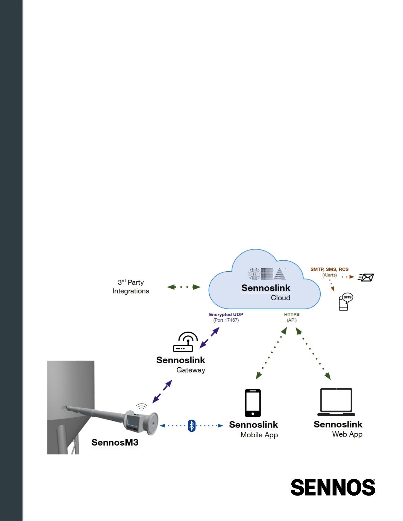
Figure 2 -1: Sennos System Diagram
Introduction
6 | Page
2.2 System Architecture Overview
The Sennos platform consists of three integrated components: the SennosM3 hardware device, the
Sennoslink application, and SennosIQ cloud analytics.
2.2.1
SennosM3 Hardware
The SennosM3 is a modular fermentation probe composed of a control module and one or more
interchangeable intelligent sensor modules (ISMs). It connects to a fermentation vessel via a standard
1.5-inch tri-clamp fitting and continuously transmits measurement data to the Sennos cloud. The
hardware is designed for fermentation facility environments and supports routine cleaning and
sanitation procedures.
2.2.2
Sennoslink
Sennoslink is the operational foundation of the Sennos platform, a cloud-based application accessible
via web and mobile that ensures your SennosM3 is connected, configured, and delivering reliable data
to your team. It provides complete system visibility and control, including real-time data display and
storage, without analytical complexity. See Section 4.3.1 for supported network requirements.
2.2.3
SennosIQ
SennosIQ is an intelligence layer built on top of Sennoslink. It processes the fermentation data
collected and stored by Sennoslink, adding automated benchmarking, intelligent alerting, and
performance analytics. SennosIQ helps fermentation operators maintain consistency, detect issues
early, and optimize fermentation processes.
2.3 About This Guide
This guide covers installation, operation, and maintenance of the SennosM3 fermentation monitoring
system. It is structured to follow the typical deployment workflow:
hardware understanding device
setup & connectivity Sennoslink account setup fermentation monitoring maintenance
& support .
Section
Description
Introduction
System overview, intended use, audience,
and safety notices
System Components & Hardware
Overview
Hardware device, sensor modules, display,
controls, and specifications
Installation & Physical Setup
Pre-installation checklist, power-on, Wi-Fi
setup and connectivity, tank mounting, and
verification
Getting Started with Sennoslink
Software overview, account setup, interface
navigation, and device management
Introduction
7 | Page
Cleaning, Handling & Storage
Cleaning procedures, maintenance guidance,
and storage instructions
Troubleshooting & Support
Common issues, diagnostics, and support
procedures
Safety, Compliance & Specifications
Device operating limits, safety guidance, and
regulatory information
This guide focuses on the SennosM3 hardware and its integration with the Sennos platform. Detailed
instructions for advanced data analysis and platform administration are available in the Sennoslink
user guide.
2.4 Intended Use & Operating Environment
The SennosM3 is designed for use in fermentation facilities to monitor conditions within production
vessels. The system is intended to:
• Install on standard 1.5-inch tri-clamp fermentation vessel ports
• Operate within typical fermentation temperature and humidity conditions
• Transmit data via supported 2.4 GHz Wi-Fi networks
Use of the device outside documented operating conditions may affect measurement accuracy, device
performance, or system reliability.
2.5 Intended Audience
This guide is intended for personnel responsible for fermentation monitoring and production
operations, including:
• Fermentation professionals, including brewers, vintners, distillers, and cellar operators.
• Production and quality assurance teams
• Technical operators responsible for device setup and maintenance
• Administrators managing users, alerts, and fermentation data in the Sennos platform
This guide does not replace standard safety procedures or facility operating policies. Users must
follow their organization's established sanitation, safety, and operational practices when working with
fermentation equipment and chemicals.
2.6 Safety Notices
The SennosM3 must be operated within the limits defined in this guide. Do not use the device in a
manner not specified by the manufacturer. For all safety warnings, operating limits, and compliance
information, see Section 8 - Safety, Compliance & Specifications.
System Components & Hardware Overview
8 | Page
3 System Components & Hardware Overview
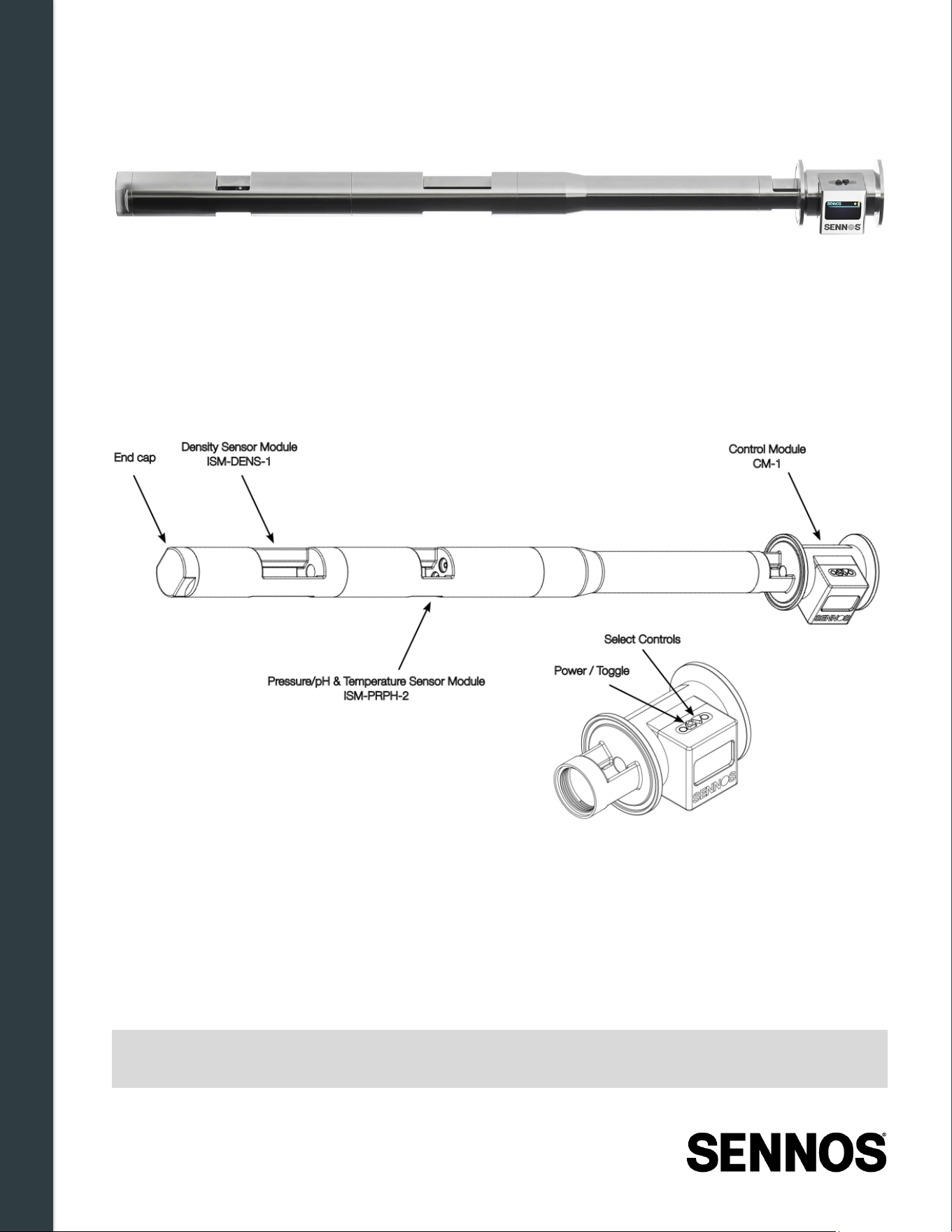
Figure 3-1. Sennos3 Modular Sensor Stack Assembly
The SennosM3 is a modular hardware device that collects fermentation measurements directly from a
fermentation vessel. This chapter describes the physical device, its hardware components, and the
interfaces used during installation and operation.
3.1 Device Architecture
Figure 3-2. SennosM3 Sensor Stack Overview
The SennosM3 is built as a modular sensor stack consisting of a control module and one or more
interchangeable intelligent sensor modules (ISMs). Each module performs a specific function within
the system, while the control module coordinates power, data collection, and wireless communication
across the entire stack.
The assembled device installs directly on a compatible fermentation vessel port and collects
fermentation measurements continuously during operation. Depending on installed modules, the
device can monitor temperature, pressure, pH, density, and other supported parameters.
Note:
Only user-serviceable module joints intended for assembly or reconfiguration should be
adjusted. Some joints are factory-secured and must not be opened by the user.
System Components & Hardware Overview
9 | Page
3.2 Hardware Modules
The SennosM3 system is built from a set of modular hardware components. Each module connects to
form a coordinated measurement stack inside the fermentation vessel. The Control Module serves as
the system core, while Intelligent Sensor Modules (ISMs) extend its measurement capabilities.
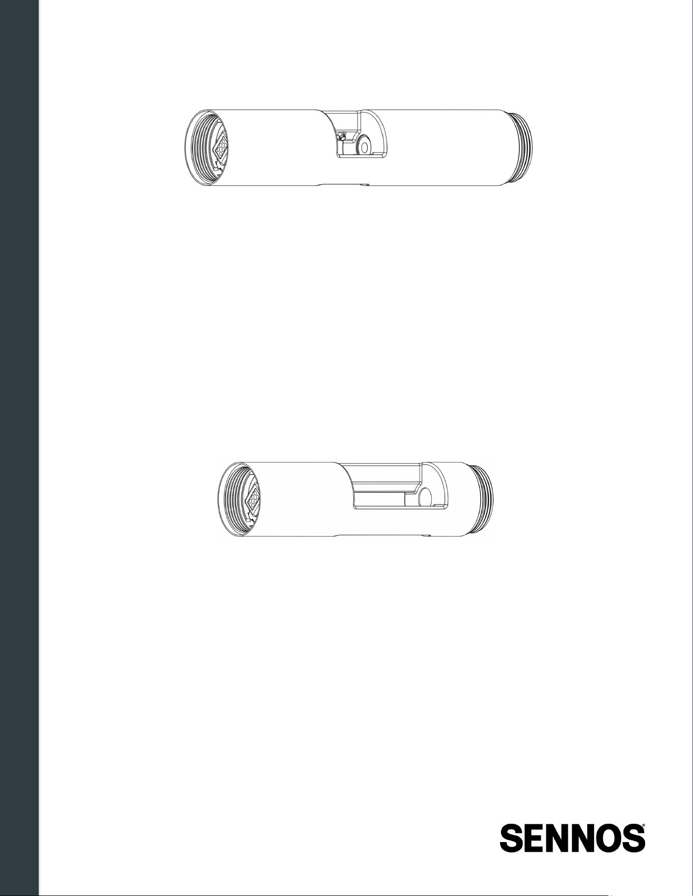
3.2.1
Control Module (ISM -CM01)
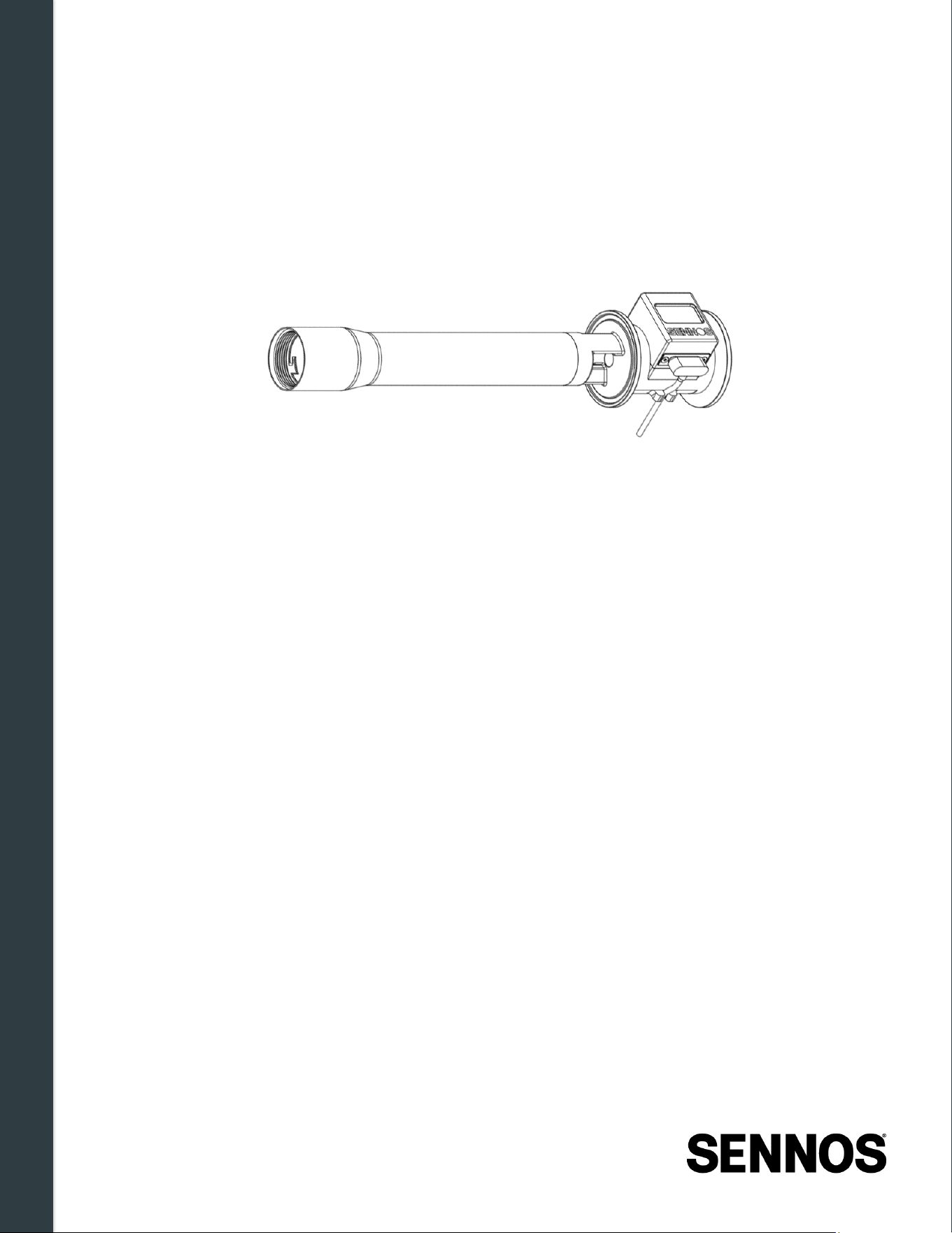
Figure 3-3. SennosM3 Control Module (ISM -CM01)
The Control Module is the operational core of the SennosM3 system. It manages local data
processing, coordinates activity across all connected sensor modules, and handles wireless
communication with the Sennos cloud platform.
The Control Module provides the following functions:
• Local device operation and system coordination
• Continuous data collection from all installed ISMs
• Wi-Fi and Bluetooth (BLE) wireless connectivity
• Edge processing
• Sennoslink connectivity for cloud data transmission
• Temporary offline data storage, uploaded automatically when connectivity is restored
• Magnetic charging support
The Control Module houses the device display, control buttons, optional battery, and all
communication hardware. Two tank extension tube sizes are available to accommodate different
vessel configurations:
• 6cm Extension — For vessels where a shorter extension is required. Does not include an
integrated battery.
• 12cm Extension — For vessels where a longer extension is required. May include an
integrated 13Wh battery, enabling cable-free operation.
The appropriate tube configuration depends on the vessel geometry and whether cable-free operation
is needed. Contact Sennos Support if you are unsure which configuration is correct for your setup.
System Components & Hardware Overview
10 | Page
3.2.2
Pressure, pH & Temperature Sensor Module (ISM -PRPH -2)
Figure 3-4. Pressure, pH, & Temperature Sensor Module (ISM -PRPH-2)
The Pressure, pH & Temperature Sensor Module is an intelligent sensor module designed for direct
exposure to fermentation conditions inside the vessel. It provides continuous, simultaneous
measurement of three critical fermentation parameters.
Measured parameters:
• pH — monitors yeast health, fermentation progress, and acid development throughout
fermentation
• Pressure — supports safe CO₂ retention and release for natural carbonation and spunding
• Temperature — maintains consistent fermentation performance and flavor from pitch to
conditioning
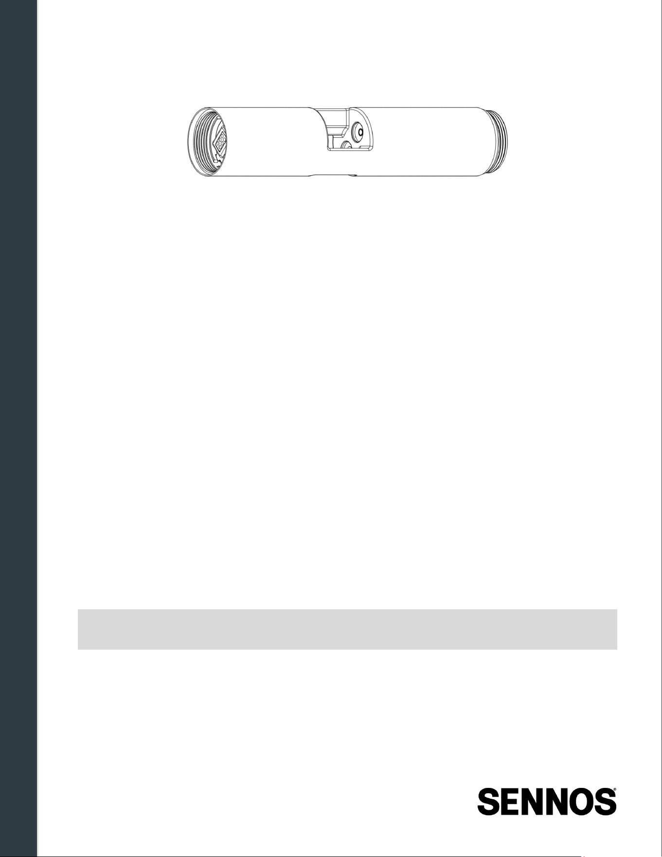
3.2.3
Density Sensor Module (IS M -DENS -1)
Figure 3-5. Density Sensor Module (ISM -DENS-1)
The Density Sensor Module is an inline sensor module that monitors fermentation progression
through continuous gravity measurement. It tracks the concentration of sugars dissolved in the
fermenting liquid, providing real-time data from pitch through to final packaging.
Measured parameters:
• Fermentation gravity (liquid density) — indicates fermentation progress and attenuation
• Sugar concentration — shows residual fermentable extract
• Alcohol content (derived) — estimates ABV based on density change
The module applies temperature compensation to gravity readings to ensure measurement accuracy
across varying fermentation temperatures.
System Components & Hardware Overview
11 | Page
3.2.4
Intelligent Fusion Module ( ISM -5MCR -1)
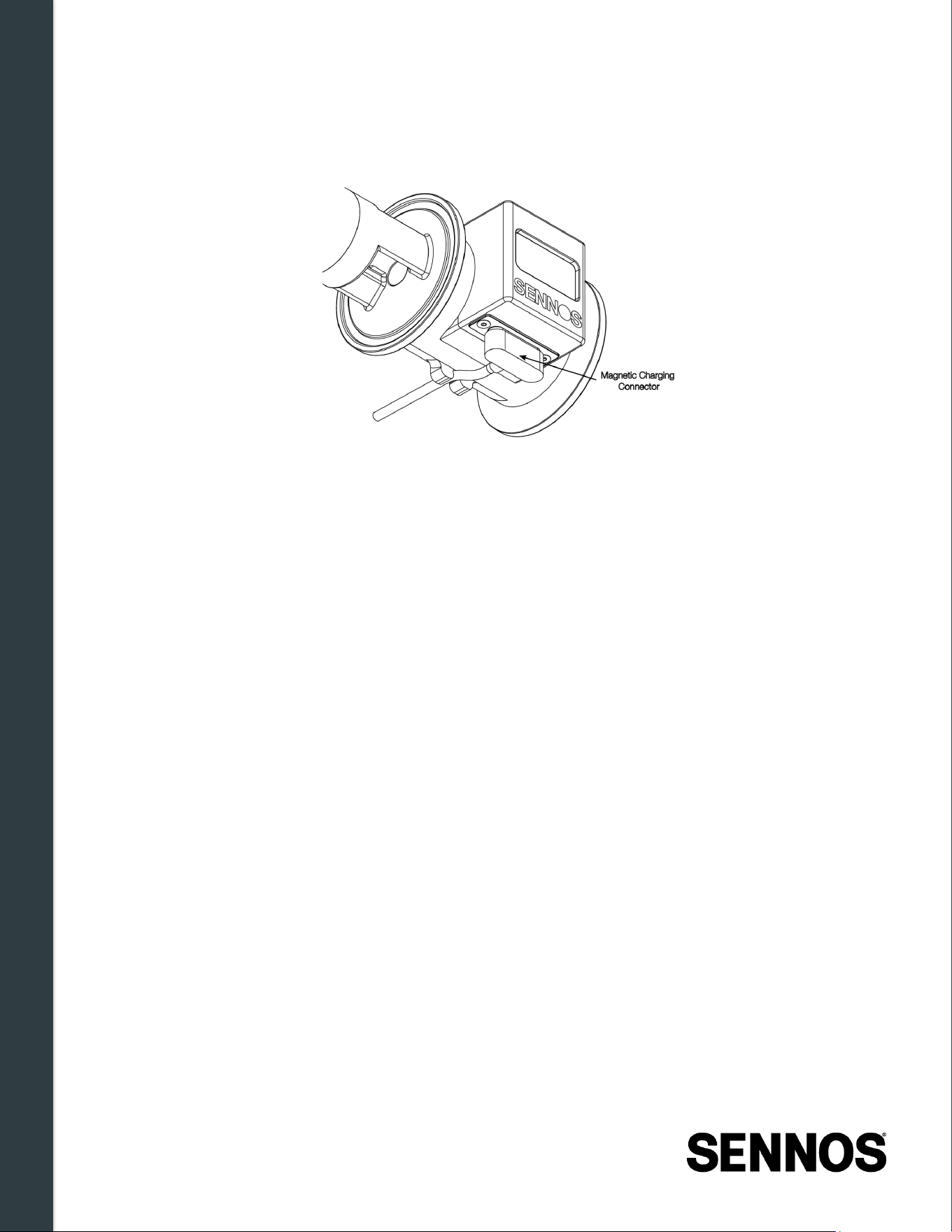
Figure 3 -6. 5-Metric Multi -sensor Module (ISM-5MCR-1)
The Intelligent Fusion Module (IFM), combines pH, dissolved oxygen, conductivity, temperature, and
pressure sensing in a single in-tank unit, delivering high-resolution visibility into the core conditions
that drive fermentation. It reduces installation complexity by consolidating multiple probes into a single
sensing point, while still providing the depth of data needed to understand yeast vitality, process
hygiene, and tank conditions in real time.
Measured parameters:
• pH — tracks yeast health, fermentation progress, and acid development throughout
fermentation.
• Dissolved oxygen (ppm) — monitors oxygen availability for yeast metabolism and supports
healthy fermentation kinetics, rather than ultra-low packaging DO control.
• Conductivity (µS/cm) — reflects ionic changes related to process hygiene, cleaning
effectiveness, and potential contamination events.
• Temperature (with compensation) — stabilizes pH, DO, and conductivity trends across
changing fermentation temperatures.
• Pressure — supports safe CO₂ retention and release for natural carbonation and spunding.
3.3 Integrated Measurement Parameters
When the sensor stack is fully assembled and powered, all modules operate as a coordinated
measurement system. Readings are collected continuously, processed by the control module, and
transmitted Sennoslink. The full set of supported parameters is determined by which sensor modules
are included in your SennosM3 device configuration.
Note:
Actual parameters available depend on which sensor modules are installed. Verify the
installed module configuration before beginning a fermentation.
System Components & Hardware Overview
12 | Page
3.4 Physical Interfaces
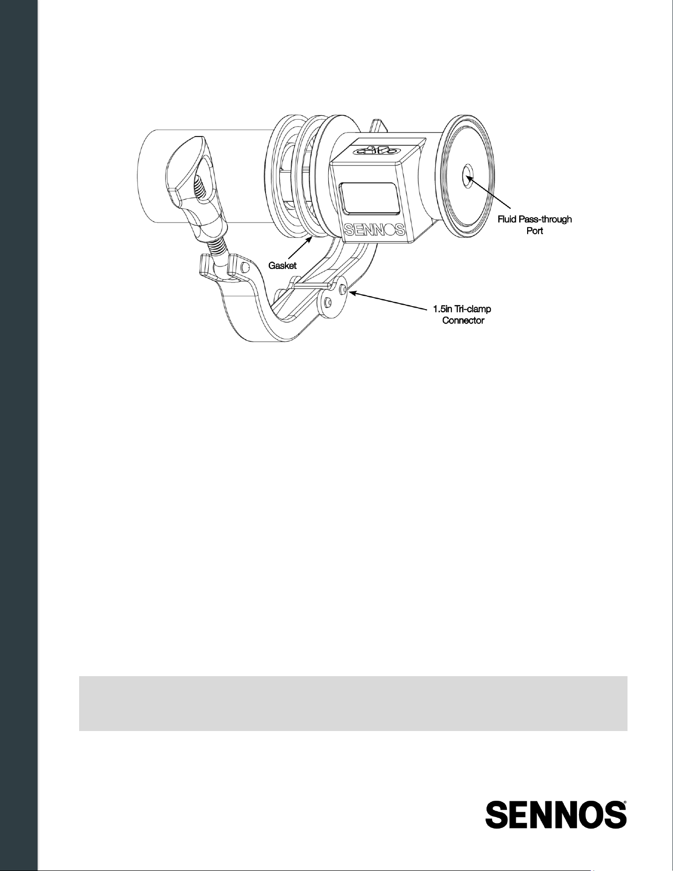
3.4.1
Magnetic Charging Connector
Figure 3 -7. Magnetic Charging Connector
The control module includes a magnetic charging port. The power cable connects magnetically to the
device on one end and connects to the provided wall adapter on the other. This connection is used for:
• Charging the internal battery
• Providing continuous external power during fermentation monitoring when required
A cable retention clip on the underside of the control module allows the charging cable to be pressed
in and routed securely along the bottom of the module. This keeps the cable tucked close to the
device, reducing the risk of the cable snagging during operation or the magnetic connector coming
loose.
See Section 4.4 for full power and charging requirements.
System Components & Hardware Overview
13 | Page
3.4.2
Tank Connection (Tri -Clamp Port)
Figure 3 -8. 1.5in Tri -clamp Connector / Fluid Pass -through Port
The SennosM3 connects to the fermentation vessel using a compatible 1.5-inch tri-clamp connection.
Requirements:
• Compatible 1.5-inch tri-clamp vessel port
• Minimum inner port diameter: 3.3 cm (1.3 in.)
• Port must be located above the cone and oriented horizontally
3.4.3
Fluid Pass -Through Port
Shown in Figure 3-8, the sensor stack includes an integrated fluid pass-through port that allows
manual lab samples to be taken during an active fermentation without removing the device from the
vessel. The port can be fitted with either a sanitized end cap or a sampling valve, depending on
operational preference
3.5 Display, Controls, and Indicator s
The SennosM3 includes a built-in display and two physical control buttons. These allow users to
confirm device status, view key identifiers, and perform basic operations without requiring access to
the Sennoslink application.
Note:
All information shown on the device display is also available in the Sennoslink
application. During normal operation, it is not necessary to manage device status
directly from the physical display.
System Components & Hardware Overview
14 | Page
3.5.1
Display Screen
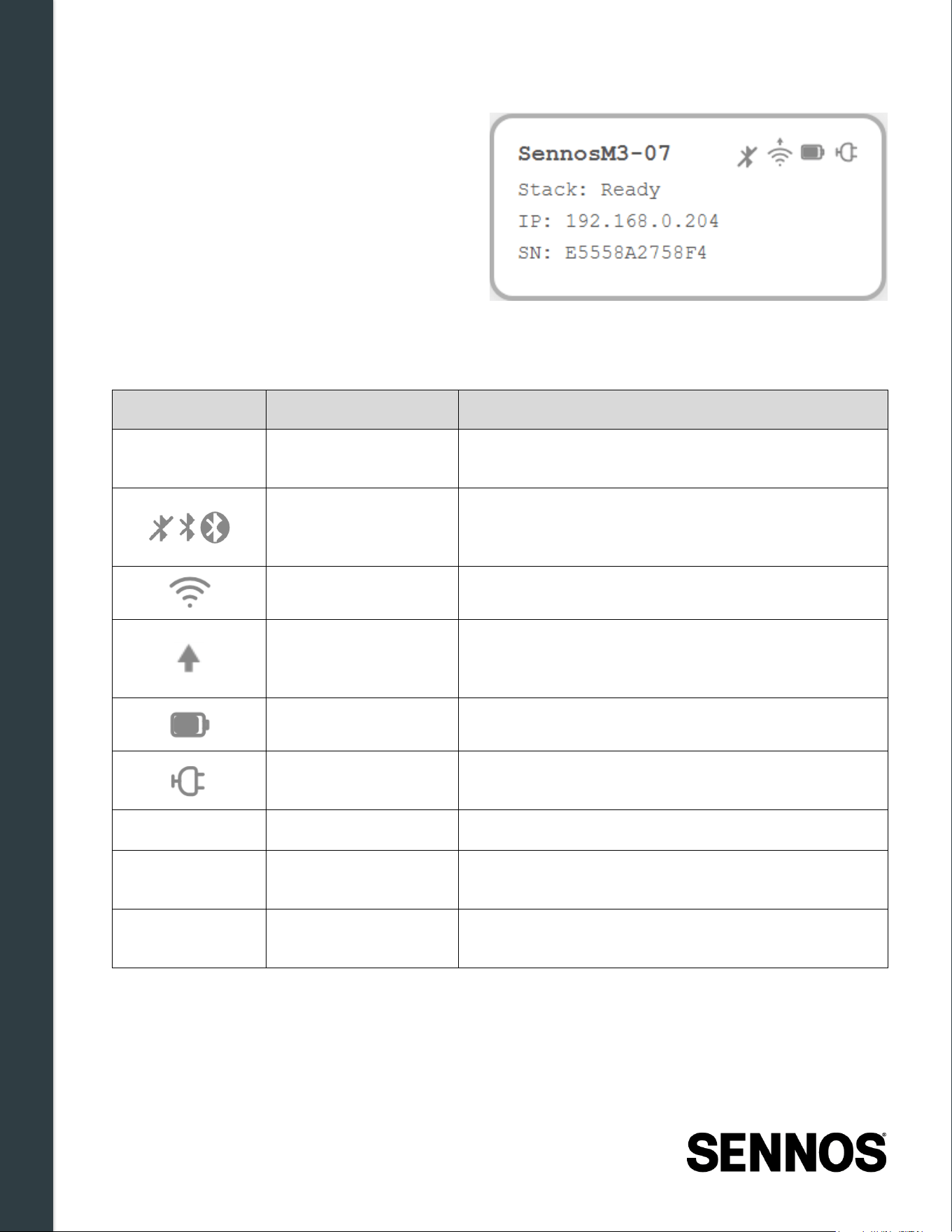
The display provides real-time device and
connectivity status. It automatically enters a
power-saving mode between sampling cycles,
this is normal behavior. The full device (not just
the screen) will wake when the Select button is
pressed once, and the boot sequence will be
visible before normal operation resumes.
Figure 3 -9. Display Screen
The display shows the following information:
Icon(s)
Display Element
Description
SennosM3-##
Device Name
Automatically assigned; matches the name shown in
the Sennoslink application
Bluetooth Status
Icon always visible when Bluetooth is enabled;
changes appearance based on connection state (see
Section 2.5.3)
Wi-Fi Signal Strength 0–4 bar scale indicating current signal strength
Cloud Connection
Status
Arrow icon appears when the device is successfully
connected to the Sennos cloud. This icon is located
above the Wi-Fi signal icon.
Battery Level Current battery charge level
Charging Indicator
Displayed when the device is connected to external
power and charging
Stack:
Stack Status Current operational state of the device (see below)
IP:
IP Address
Displayed after a successful Wi-Fi connection is
established
SN:
Serial Number (SN)
Matches the serial number printed on the physical
device; used for identification in Sennoslink
System Components & Hardware Overview
15 | Page
Stack status messages:
Status Message
Meaning
Stack: Ready
Device is powered on, properly configured, and ready to sample
Stack: Sampling
Device is actively taking a measurement
Stack: No WiFi
Device is not connected to a Wi-Fi network
Stack: No Cloud
Device is connected to Wi-Fi but not yet communicating with the
Sennos cloud
Stack: Sleeping
Device is in power-saving sleep mode. The display shows the
scheduled wake-up time in UTC. The device will resume normal
sampling and cloud communication automatically at the displayed time.
To wake the device manually before the scheduled time, press the
Select button once.
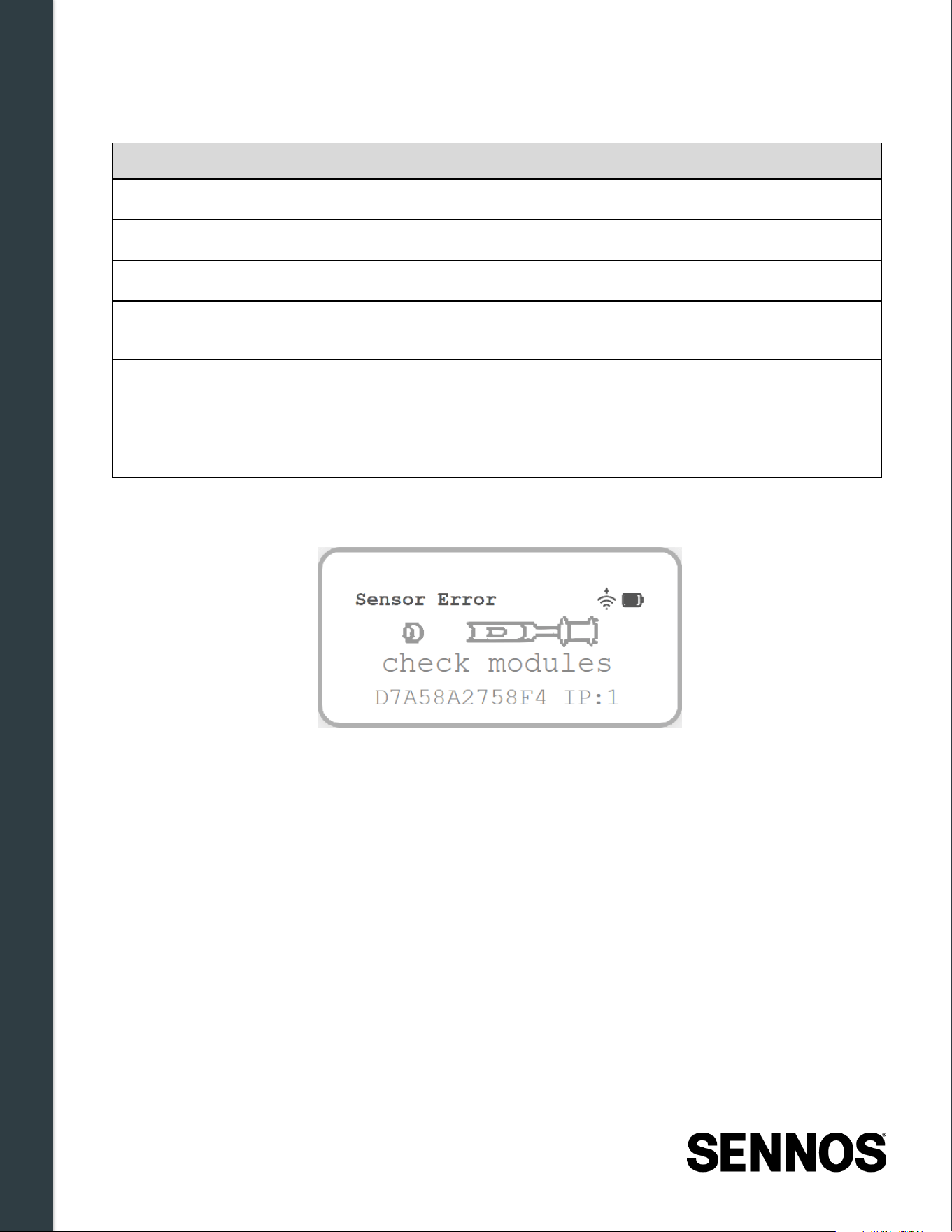
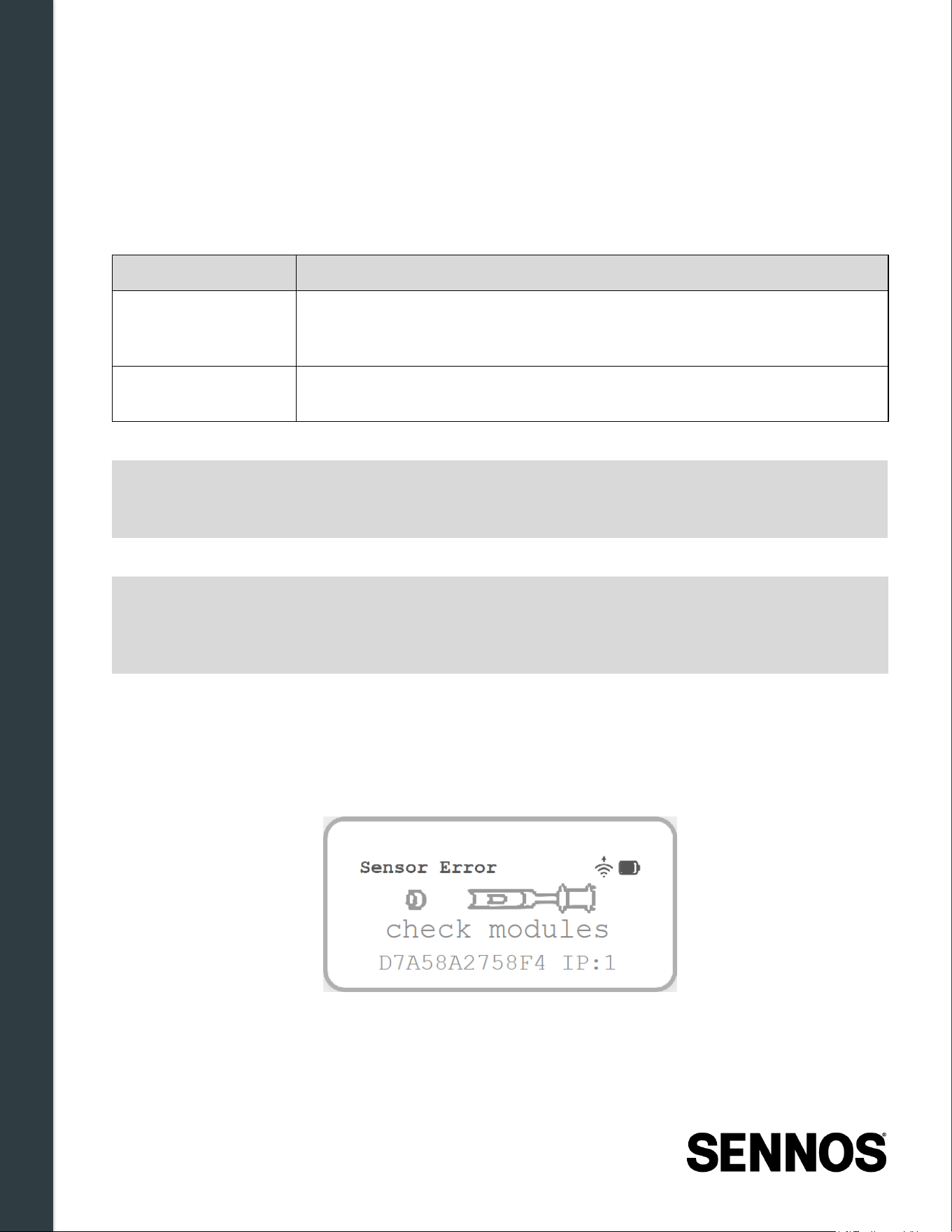
Sensor Error
Figure 3 -10. Sensor Error / Check Modules
A Sensor Error screen appears when one or more sensor modules are not fully tightened. This error
must be resolved before installation, see Section 4.2.3 – Verifying Module Connections for more
information.
System Components & Hardware Overview
16 | Page
3.5.2
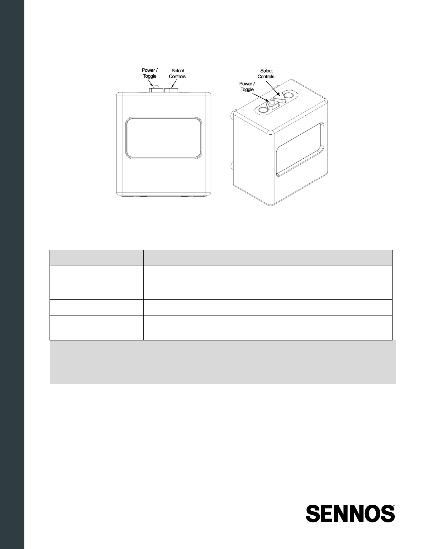
Control Buttons
Figure 3 -11. Control Buttons
The device includes a two -button interface . The power button has a raised tactile indicator on its
surface to allow identification by touch. The
select button has no raised indicator.
Action
Procedure
Power ON
Press and hold the power button (closest to the tank when installed) for
4–5 seconds. Release when the screen illuminates. The serial number
will appear during startup.
Power OFF Press and hold the power button for 4–5 seconds.
Wake from power-saving
mode
Press the select button once. The device will initiate a full boot process
before resuming normal operation.
WARNING:
While in power-saving mode, the device is still actively monitoring. Pressing and
HOLDING the power button while the probe is in power-saving mode will power it off
completely, monitoring will stop and will not resume automatically. To check the
display status between sampling cycles, use the SELECT button (single press) only.
System Components & Hardware Overview
17 | Page
3.5.3
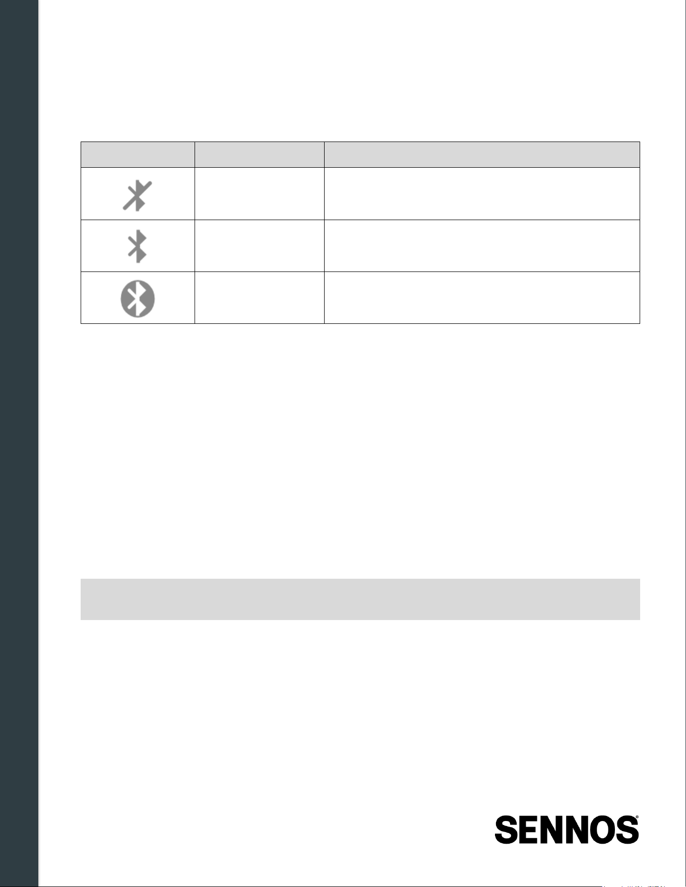
Bluetooth Status Indicator
When Bluetooth is enabled, a Bluetooth icon is always visible on the display. The icon does not
disappear, it changes appearance to reflect the current connection state.
Icon
State
Description
Disabled Bluetooth is not active; a disabled icon is shown
Enabled / Advertising Device is discoverable and ready to connect
Connected An active Bluetooth connection is established
Bluetooth is used during the following operations: Wi-Fi setup via the Sennoslink mobile application,
mobile app connection to the SennosM3, and device log retrieval. During these operations, the icon
will transition between states but will remain visible at all times.
3.6 Modular Assembly & Service Considerations
The SennosM3 sensor stack is assembled between the vessel connection point and the control
module. Proper assembly is required for normal operation. During assembly:
• Ensure all user-serviceable modules are fully seated and properly aligned
• Tighten only the module connections intended for user assembly
• Do not attempt to loosen or adjust factory-secured joints
• Verify the device is fully assembled before installation on a vessel
Improperly assembled modules may result in device warnings, communication or measurement errors,
or incomplete data collection.
WARNING:
Disassembly beyond user-serviceable joints is strongly discouraged and should only
be performed when explicitly instructed by Sennos support personnel.
System Components & Hardware Overview
18 | Page
3.7 Hardware Specifications
3.7.1
Electrical Specifications
Specification
Value
Charging Input 5 V DC, 2 A
Battery Voltage 3.7 V DC
Battery Capacity 25.9 mAh
Charging Method Magnetic connector on control module (supplied cable required)
Power Source Internal battery and/or continuous external power
Note:
The SennosM3 is designed to operate on battery power for the duration of typical
fermentation runs. In longer or more demanding applications, it may be necessary to
supply continuous external power. Use only the supplied power cable and adapter, or
approved equivalents.
3.7.2
Environmental Operating Conditions
Parameter
Supported Range
Operating Temperature −20°C to 55°C (−4°F to 131°F)
Charging Temperature 0°C to 45°C (32°F to 113°F)
Relative Humidity 10% to 95% RH, non-condensing
Altitude −100 ft to 10,500 ft (−30 m to 3,200 m)
3.7.3
Network & Connectivity Requirements
Specification
Requirement
Wi-Fi Band 2.4 GHz only
Supported Networks Standard and enterprise password-authenticated networks
Unsupported Networks 5 GHz, enterprise with certificate-based networks, captive portals
Stored Network Profiles Up to 4; reconnects to previously connected network first, then by
signal strength
System Components & Hardware Overview
19 | Page
3.7.4
Regulatory & Usage Classification
Attribute
Description
Intended Use Indoor use only
Pollution Degree Rating PD2
Device Classification Fermentation monitoring system
Use Limitation Must be operated as specified by the manufacturer
WARNING:
If the equipment is used in a manner not specified by the manufacturer, the protection
provided by the equipment may be impaired.
Installation & Physical Setup
20 | Page
4 Installation & Physical Setup
This chapter provides step-by-step instructions for preparing, mounting, and verifying the SennosM3
installation on a fermentation vessel. Complete all steps in order before beginning a fermentation.
4.1 Pre -Installation Checklist
Complete the following steps before mounting the SennosM3 on a tank:
• Retain original packaging. Keep all packaging materials in case the device requires return or
service.
• Verify module connections. Ensure all SennosM3 modules are fully tightened together.
Loose modules cause inaccurate readings or device errors.
• Remove the pH Storage Reservoir (shipping cover). Remove, rinse, and retain the pH
Storage Reservoir before installing on a fermentation vessel. This reservoir will be used later
for storage purposes.
• Charge the device to 100%. Use the provided magnetic power cable and adapter. An
extension cord may be required depending on tank location. See Section 3.3 for continuous
power options.
• Sanitize the probe and tri -clamp port. Using your standard sanitization procedure, sanitize
the SennosM3 sensor assembly and the tri-clamp port on the fermentation vessel before
installation.
4.2 Initial Device Power -On
Complete the following steps to power on the SennosM3 and verify it is ready for installation.
Note:
Power on the device and complete all checks in this section before mounting on the
tank. Module connections cannot be adjusted once the device is installed.
4.2.1
Power -On Procedure
1. Ensure the device is fully charged or
connected to external power using the
provided power cable and adapter.
2. Press and hold the power button
(closest to the tank when installed) for
4–5 seconds.
3. Release the button when the device
screen illuminates.
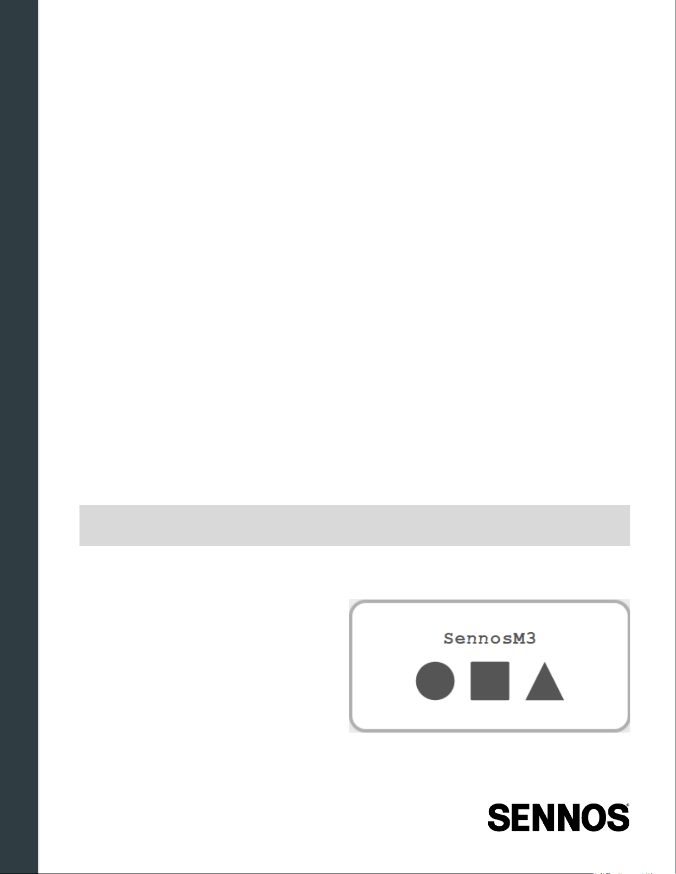
Figure 4 -1: Initial Boot Screen
Upon successful power-on, the display shows the device serial number, battery level, Wi-Fi status (if
Installation & Physical Setup
21 | Page
previously configured), and current device status.
4.2.2
Waking the Device from Power -Saving Mode
The display automatically enters power-saving mode between sampling cycles. The device remains
active and continues monitoring in this state.
Action
Procedure
Wake the display Press the Select button (the button
without
the raised tactile indicator)
once. The device will complete a full boot sequence before resuming
normal operation.
Power OFF Press and hold the power button (the button with the raised tactile indicator)
for 4–5 seconds.
Note:
Connecting the power cable does not wake the device from sleep mode, it only
prevents the device from returning to sleep once it is already awake. To wake the
device, press the Select button once, or wait for the next scheduled sampling cycle.
WARNING:
Always use the SELECT button (single press) to wake the device between sampling
cycles. Pressing and HOLDING the power button while the device is in power-saving
mode will power it off completely. Monitoring will stop and will not resume
automatically.
4.2.3
Verifying Module Connections
After powering on, check the display for a Sensor Error screen. If one or more sensor modules are
not fully tightened, the display will show a sensor diagram indicating which module is not detected,
along with the message
Check Modules .
Figur e 4-2: Sensor Error
If a Sensor Error is displayed:
1. Power off the SennosM3.
2. Inspect all module connections and tighten any that are loose.
Installation & Physical Setup
22 | Page
3. Power the device back on and confirm the Sensor Error no longer appears.
Note:
A power cycle is required to clear a Sensor Error after re-tightening modules. If the
error persists after tightening and power cycling, see Section 7 – Troubleshooting &
Support before proceeding with installation.
4.3 Wi -Fi & Connectivity Requirements
The SennosM3 requires a wireless network connection to transmit fermentation data to the Sennos
cloud via Sennoslink. Proper network configuration is required before beginning a fermentation.
Note:
If this is not the first time connecting the device to Wi-Fi, connect it to external power
before proceeding. After the initial Wi-Fi setup, the device will enter power-saving mode
on battery and may go to sleep before configuration completes. Keeping it plugged in
eliminates this issue.
4.3.1
Supported Network Types
Requirement
Detail
Wi-Fi band 2.4 GHz only — 5 GHz networks are not supported
Standard authentication Password-protected networks using standard authentication are
supported
Enterprise networks
Password-based enterprise networks are supported. Enterprise
networks that use client-certificate authentication are not supported.
Unsupported
configurations
Networks requiring captive portals, secondary login pages, or browser-
based authentication are not supported
Stored network profiles The device stores up to 4 Wi-Fi network profiles. It will always attempt
to reconnect to a previously connected network first. For other stored
networks, it will attempt connection in order of signal strength.
Note:
If your facility network uses a firewall, additional configuration may be required before
the SennosM3 can reach the Sennos cloud. See Section 7.3.5 – Firewall Configuration
for requirements.
Installation & Physical Setup
23 | Page
4.3.2
Wi -Fi Connection Process
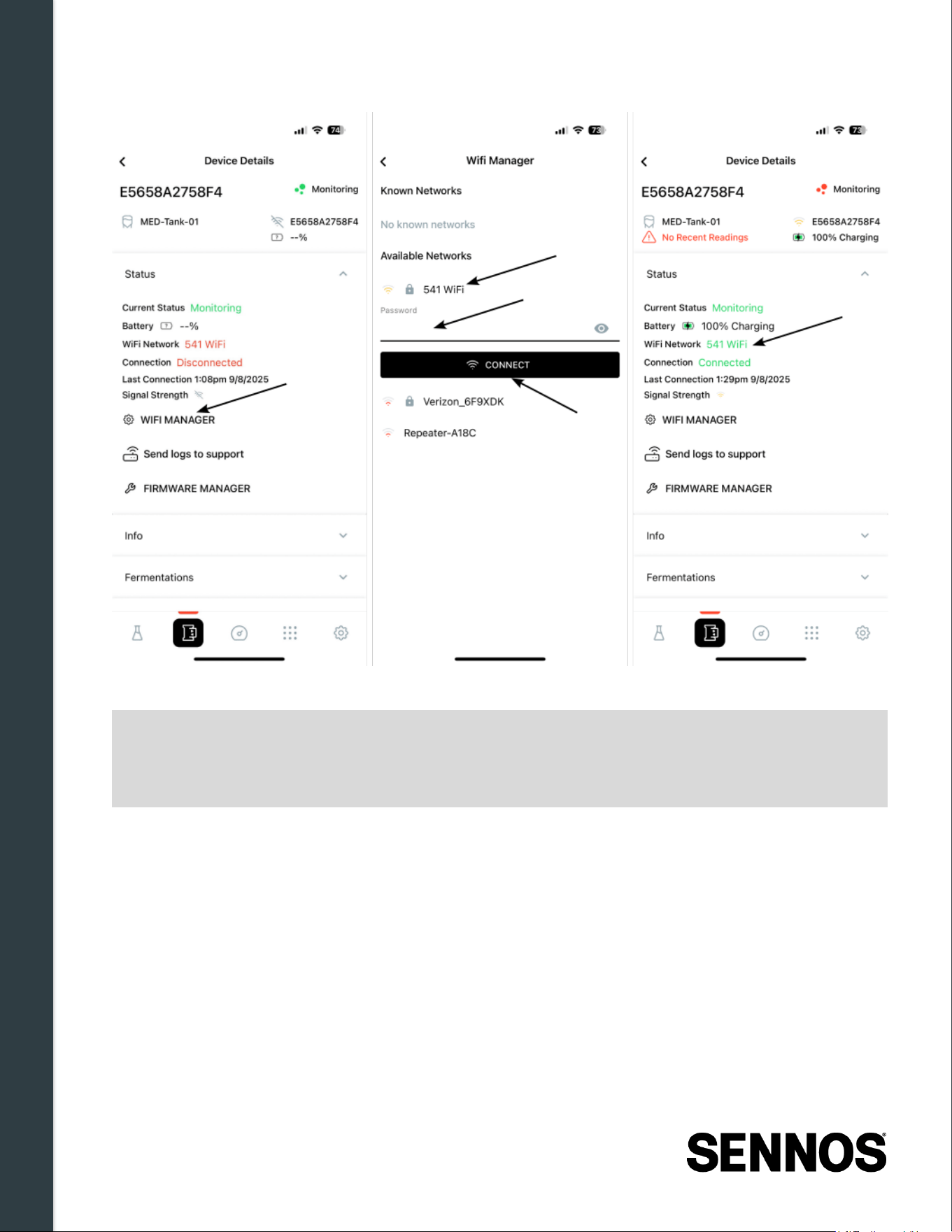
Complete the following steps to connect the SennosM3 to a Wi-Fi network:
1. Power on the SennosM3.
• Press and hold the power button (closest to the tank) for 4–5 seconds.
• The Sennos logo appears first, followed by the device serial number once fully booted.
Note:
If this is not the first time connecting the device to Wi-Fi, connect it to external power
before proceeding. After the initial Wi-Fi setup, the device will enter power-saving mode
on battery and may go to sleep before configuration completes. Keeping it plugged in
eliminates this issue.
2. Open the Sennoslink mobile application.
• Log in to your Sennoslink account.
3. Navigate to Devices.
• Tap the Devices tab in the app.
• Tap the device card for the device you want to connect.
4. Open Wi -Fi Manager.
• Select Wi-Fi Manager .
5. Select or add a network.
• Choose an available network from the list, or
• Select Add Hidden Network to enter an SSID manually.
6. Enter credentials and connect.
• Enter the Wi-Fi password. Passwords are case-sensitive.
• Tap Connect .
7. Confirm connection.
• Upon successful connection, the device's IP address appears on the SennosM3 display.
Installation & Physical Setup
24 | Page
Figure 4 -1. Wi-Fi Connection Process
Note:
If you encounter connection issues during this process, see Chapter 7 –
Troubleshooting & Support. The Sennoslink app will notify you when an update is
available; keeping the app current is the first step in resolving most connection
problems.
Installation & Physical Setup
25 | Page
4.3.3
Confirming Cloud Connectivity
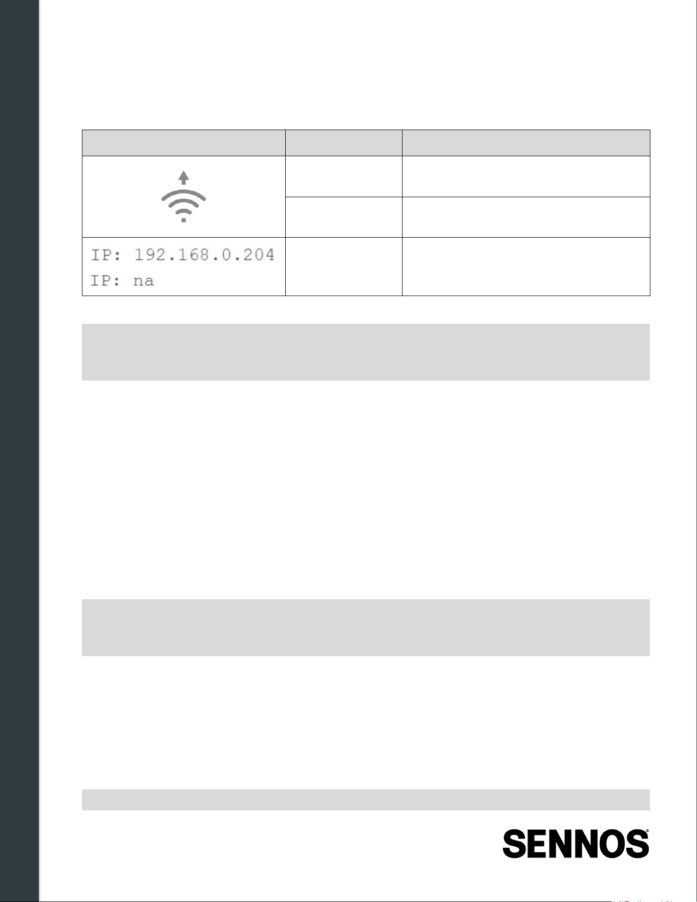
Once connected to Wi-Fi, confirm the following on the display before proceeding to tank installation:
Icon
Indicator
What to Look For
Cloud connection
icon
Arrow icon visible when successfully
connected to the Sennos cloud.
Wi-Fi signal
strength
0–4 bars; verify active bars are shown
IP address
Displayed on screen after a successful
Wi-Fi connection is established
Note:
Network stability directly affects data transmission frequency and alert delivery. If you
experience intermittent connectivity, use the connectivity test tool in Sennoslink to
diagnose signal issues at your installation location.
4.3.4
Normal Operation
When the SennosM3 is installed on a fermentation vessel and connected to Wi-Fi, it continuously
collects fermentation readings and transmits them to the Sennos cloud via Sennoslink. Data is
associated with the active fermentation started in Sennoslink and is immediately accessible through
the web and mobile applications. See Figure 2-1: Sennos System Diagram for visual representation.
4.3.5
Offline Data Storage
If the SennosM3 loses Wi-Fi connectivity during an active fermentation, it continues collecting readings
and stores them internally, as long as the device remains powered on. Stored readings are uploaded
to Sennoslink automatically when connectivity is restored.
Note:
The device can store up to approximately one week of offline readings. Data collection
stops if the device loses power. If connectivity is lost for an extended period, keep the
device plugged in to power to ensure readings continue uninterrupted.
4.3.6
Uploading After a Connectivity Gap
When the device reconnects to Wi-Fi after a period offline, it begins uploading stored readings. This
upload is not instantaneous; the device transmits in intervals rather than continuously. To speed up
the upload process, connect the device to external power. This prevents the device from entering
power-saving mode between upload cycles and allows it to finish uploading all stored readings as
quickly as possible.
Note:
Under normal conditions, the device keeps up with data uploads in real time. The
Installation & Physical Setup
26 | Page
catch-up behavior described here applies only when the device has been offline for an
extended period and has accumulated a backlog of stored readings.
4.4 Power Requirements & Charging
The SennosM3 contains an internal rechargeable battery sufficient for most fermentations. For long or
critical fermentations, Sennos recommends operating the device connected to continuous external
power or with a Sennos battery pack attached.
4.4.1
Power Input Requirements
Specification
Value
Charging Input 5 V DC, 2 A
Charging Connector Magnetic connector on control module (supplied cable required)
Wall Adapter Supplied 5 V, 2 A adapter
An extension cord may be required depending on tank location and facility layout.
4.4.2
Battery Operation
• Battery level is displayed on the device screen and in the Sennoslink application.
• A charging icon appears on the display when external power is connected.
• If battery power is low, the device may enter a sleep state to conserve power.
• Battery alerts can be configured in Sennoslink to notify users when the battery is low or critical.
Note:
For long or critical fermentations, Sennos recommends operating the SennosM3 while
connected to continuous external power or with a Sennos battery pack attached.
4.4.3
Charging Procedure
1. Connect the supplied magnetic power cable to the charging connector on the SennosM3 the
cable can be secured by placing it in the cable retention clip.
2. Plug the cable into the provided wall adapter (5 V, 2 A).
3. Connect the adapter to a suitable AC power source.
4. Verify charging status using the battery and charging indicators on the display.
Installation & Physical Setup
27 | Page
4.4.4
Charging Temperature Limits
Charge the device only within the following temperature range:
• Charging temperature: 0°C to 45°C (32°F to 113°F)
Charging outside this range is not recommended and may affect battery performance or longevity.
4.5 Mounting the SennosM3 on a Tank
4.5.1
Mounting Requirements
Before installing the SennosM3, verify the following:
• The fermenter has a 1.5-inch tri -clamp port with a minimum inner diameter of 33 mm (1.3 in.)
• The selected port is located above the cone and oriented horizontally
• The fermenter has been cleaned and sanitized.
4.5.2
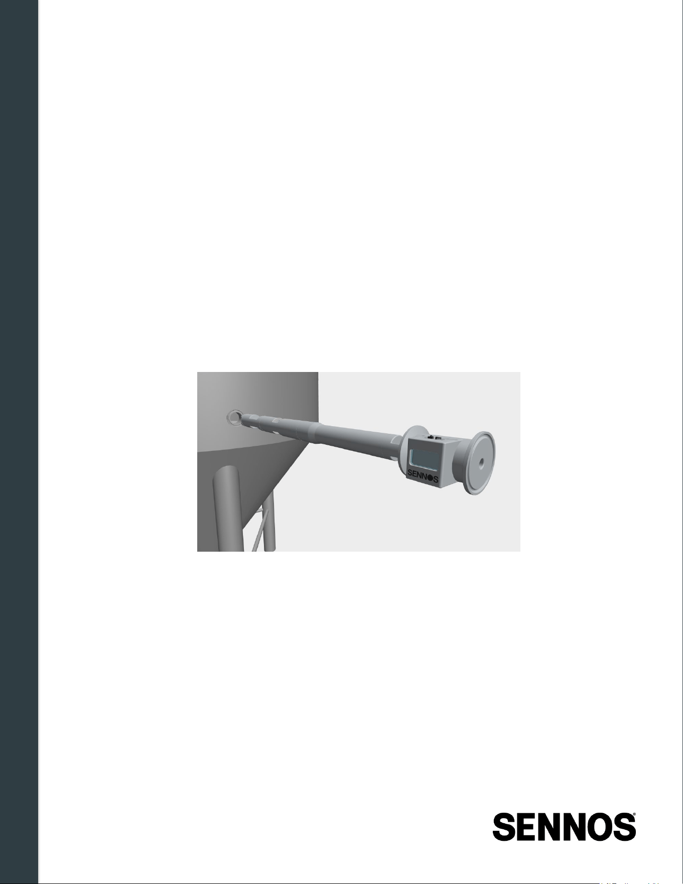
Installation Orientation
Figure 4 -1. Installation Orientation
The SennosM3 must be installed in the correct orientation for proper sensor function and display
visibility:
• The display screen must face sideways
• The control buttons must be positioned above the display
Installation & Physical Setup
28 | Page
4.5.3
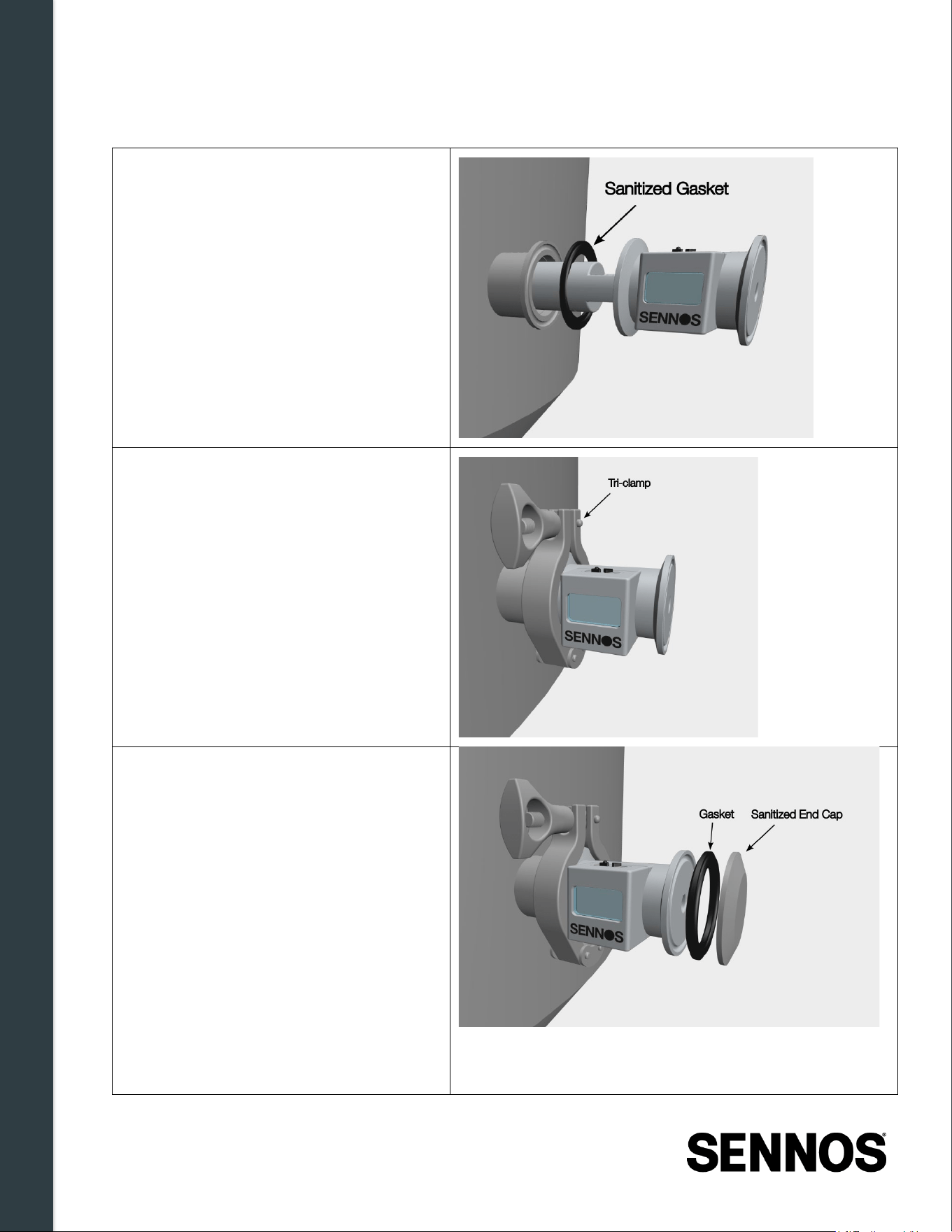
Mounting Procedure
1. Confirm that all sensor modules are
fully tightened to the control module.
2. Sanitize the probe and tri-clamp port.
3. Place a sanitized gasket on the tri-
clamp port fitting.
4. Insert the SennosM3 sensor stack
into the selected tri-clamp port,
ensuring correct orientation.
5. Secure the device with the tri-clamp.
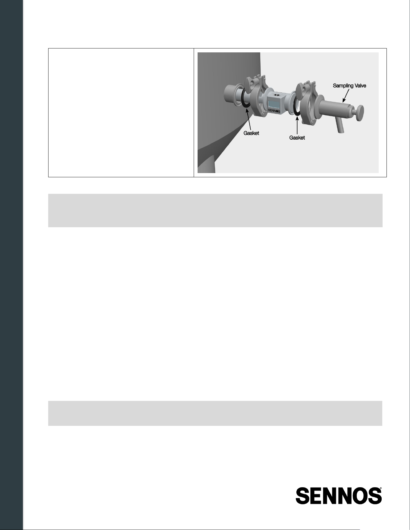
6. Attach one of the following:
a. Attach a sanitized end cap to the
fluid pass-through port.
or
Installation & Physical Setup
29 | Page
b. Attach a sampling valve to the fluid
pass-through port.
7. Complete tank sanitization according
to standard procedures.
WARNING:
Any Sensor Error displayed on the device screen must be resolved before proceeding
with installation. Loose or improperly seated modules can result in inaccurate
readings or device errors. See Section 7.1.3 for troubleshooting steps.
4.5.4
Post -Installation Verification Checklist
After mounting, confirm each of the following:
☐ Module integrity - No Sensor Error screen is displayed.
☐ Device name - The name on the display matches the name shown in the Sennoslink
application.
☐ Wi-Fi signal - The signal strength indicator shows active bars.
☐ Cloud connection - The cloud icon is visible on the display.
☐ Stack status - Ready or Monitoring is shown on the display.
☐ IP address - An IP address is displayed (confirms active Wi-Fi connection).
☐ Power - Charging icon is shown if connected to external power; battery level shows adequate
charge if on battery.
☐ App visibility - Device appears online in the Devices section of the Sennoslink application with
no status errors.
Note:
The display may enter power-saving mode when idle. Press the Select button once to
wake it if needed.
Once all checklist items are confirmed with no warnings present, the SennosM3 is correctly installed
and ready to begin fermentation monitoring.
Installation & Physical Setup
30 | Page
4.6 ISM Module Replacement Procedure
Follow this procedure when installing a new ISM or replacing an existing module for service, upgrade,
or maintenance. Proper installation is required for accurate measurements and reliable operation.
4.6.1
Understanding the Module Stack
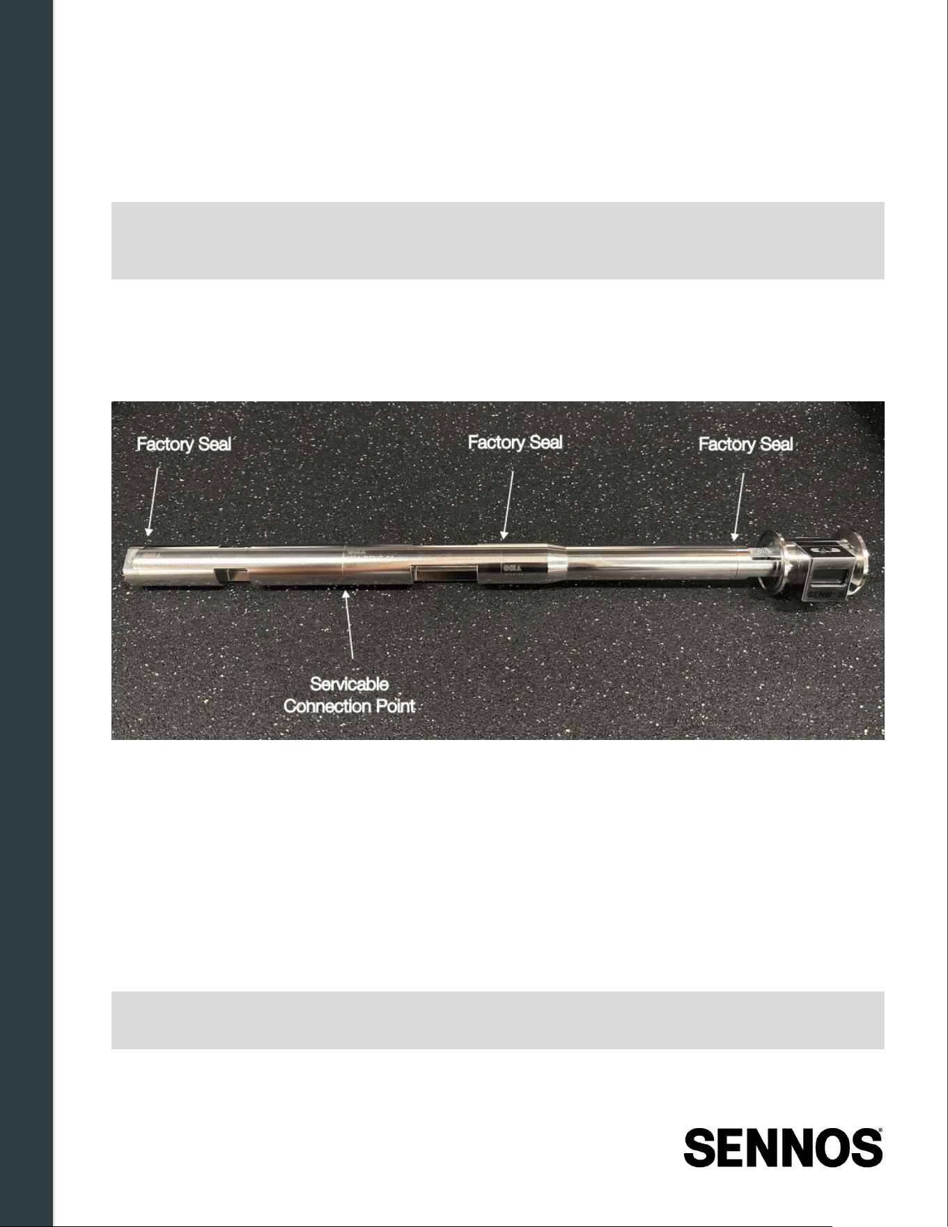
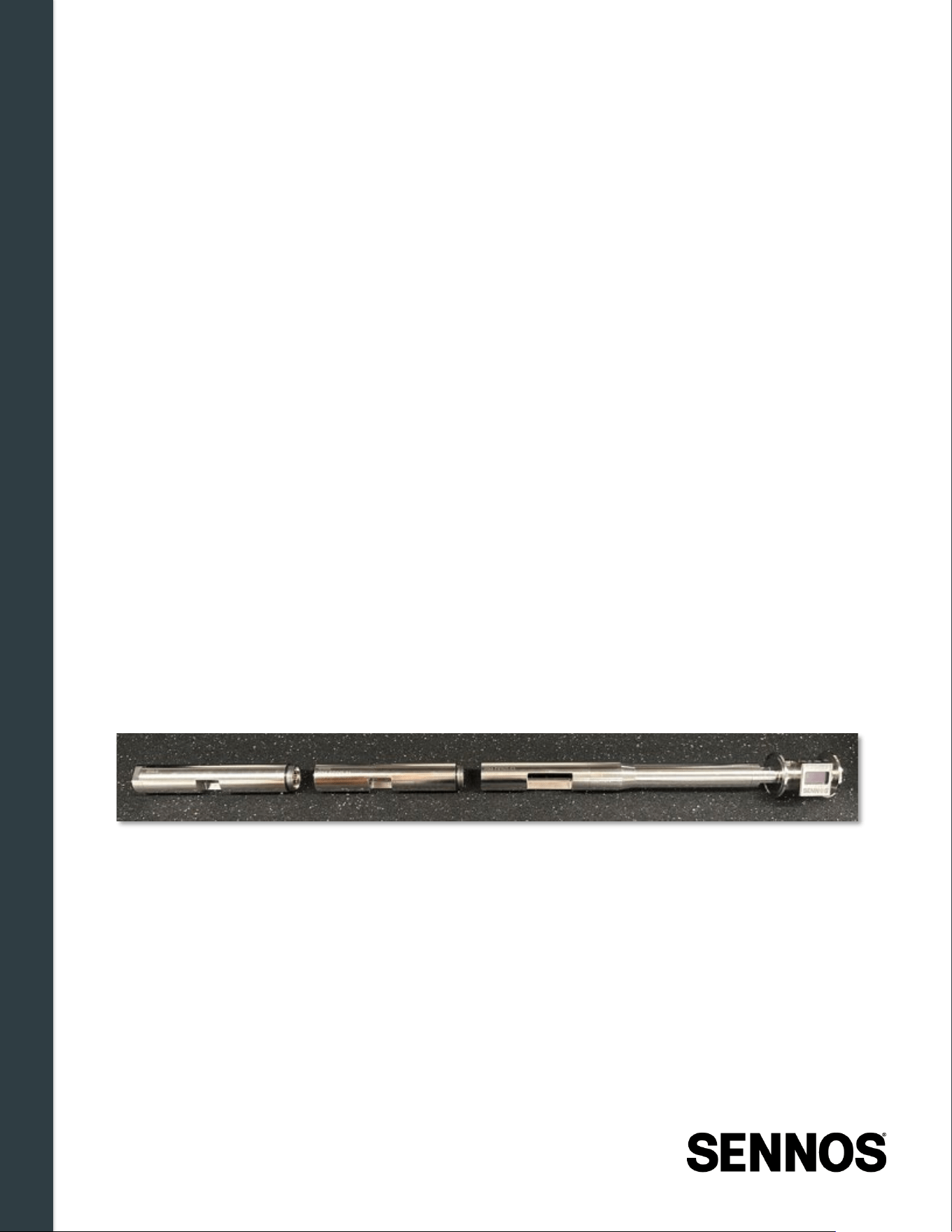
The SennosM3 consists of two factory-sealed assemblies connected by serviceable connection points.
It is critical to understand which parts of the device are user-serviceable before proceeding.
Figure 4 -2: SennosM3 Serviceable Connections and Factory Seals
Factory-sealed assemblies — do not separate:
• Top Assembly — Control Module (CM) and Gravity/Density Module (ISM-DENS)
• Bottom Assembly — Intelligent Fusion Module (ISM-5MCR) and Endcap
ISM modules may only be installed or removed at the designated serviceable connection points:
• Between the Density Module and the first ISM module
• Between ISM modules, when a second ISM is installed
WARNING:
Always power off and clean the SennosM3 before opening the sensor stack. Failure to
do so may result in device errors, inaccurate readings, or contamination of the module
connections.
WARNING:
Do not separate factory-sealed assemblies. If either assembly requires service, return
it to Sennos as a complete unit.
Installation & Physical Setup
31 | Page
4.6.2
Prepar ing for ISM Service
Before performing any ISM removal, installation, or replacement, gather the following materials:
• SennosM3 device
• New ISM module (if installing or replacing)
• Replacement gaskets (included with new ISM modules)
• Access to the Sennoslink mobile app, or access to email/SMS for removal confirmation
Then complete the following preparation steps:
• Power off the SennosM3.
• Remove the device from the fermentation vessel.
• Clean the device after removing it from the vessel and before opening the sensor stack, see
Section 6 for approved cleaning procedures.
• Work on a clean, dry surface.
• Inspect gaskets for damage or debris before reuse.
4.6.3
Removing an ISM
1. Power off the SennosM3. Press and hold the Power button until the display turns off, then wait
10 seconds for complete shutdown.
2. Remove the device from the vessel if still installed.
3. Hold the top assembly steady and unscrew the bottom assembly by rotating counterclockwise.
Set the bottom assembly aside.
4. Unscrew the ISM module from the top assembly by rotating counterclockwise. Set the module
aside.
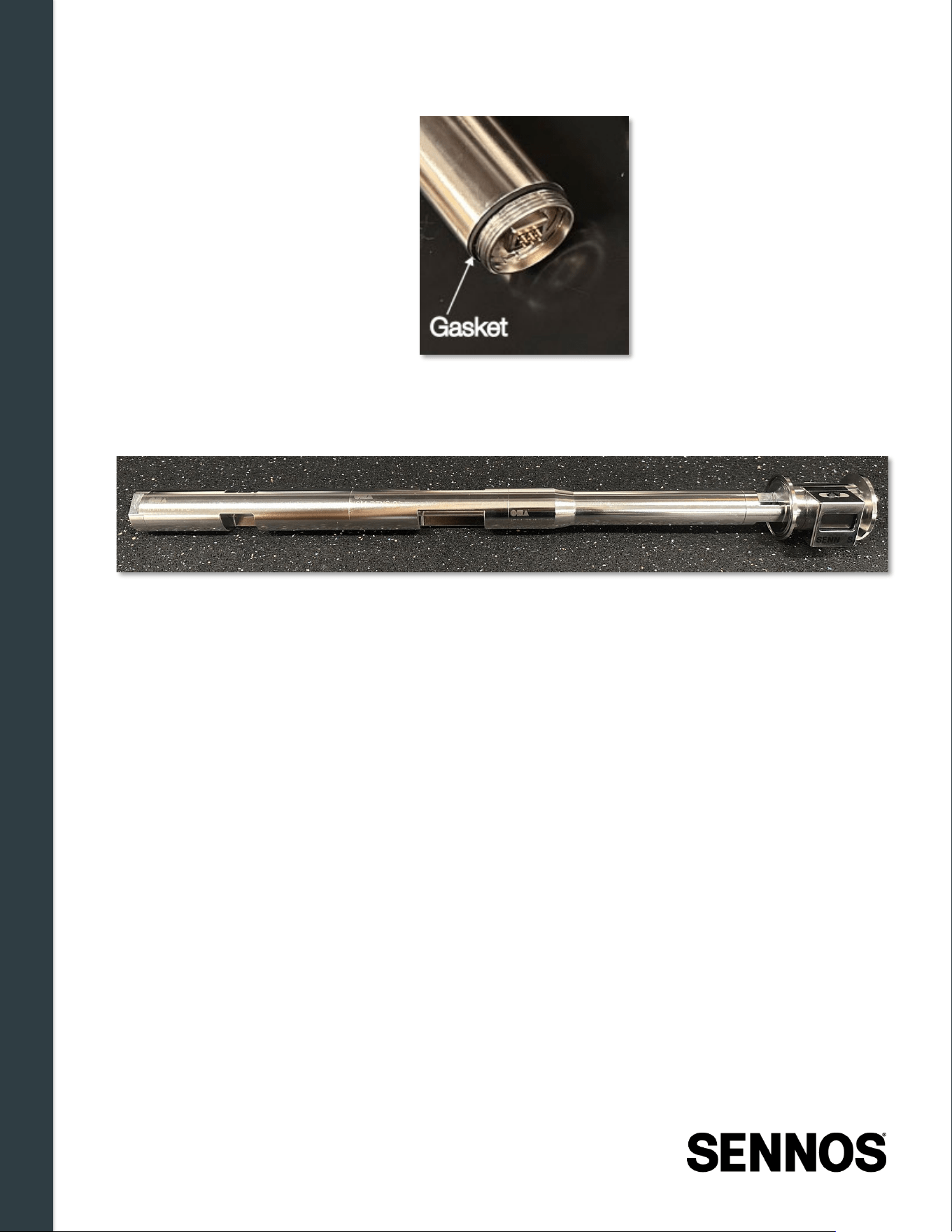
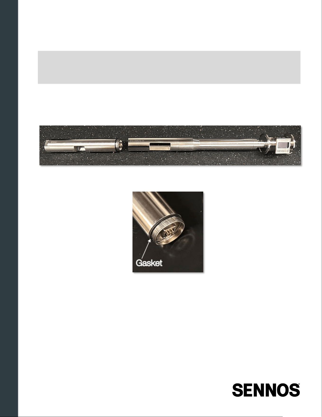
5. Remove the gaskets from both exposed connection ports at the separated serviceable
connection point. Discard the old gaskets.
Installation & Physical Setup
32 | Page
6. Install a fresh gasket on the exposed connection port of the upper module.
7. Reconnect the bottom assembly, align it with the exposed connection port, screw clockwise,
and hand-tighten until snug. Do not use tools.
8. Inspect all sealing surfaces for residue or damage.
9. Store the removed module according to the cleaning and storage guidance in Section 6.
What to Expect After Removing an ISM
When you power on the SennosM3 after removing a module, the device will detect the missing module
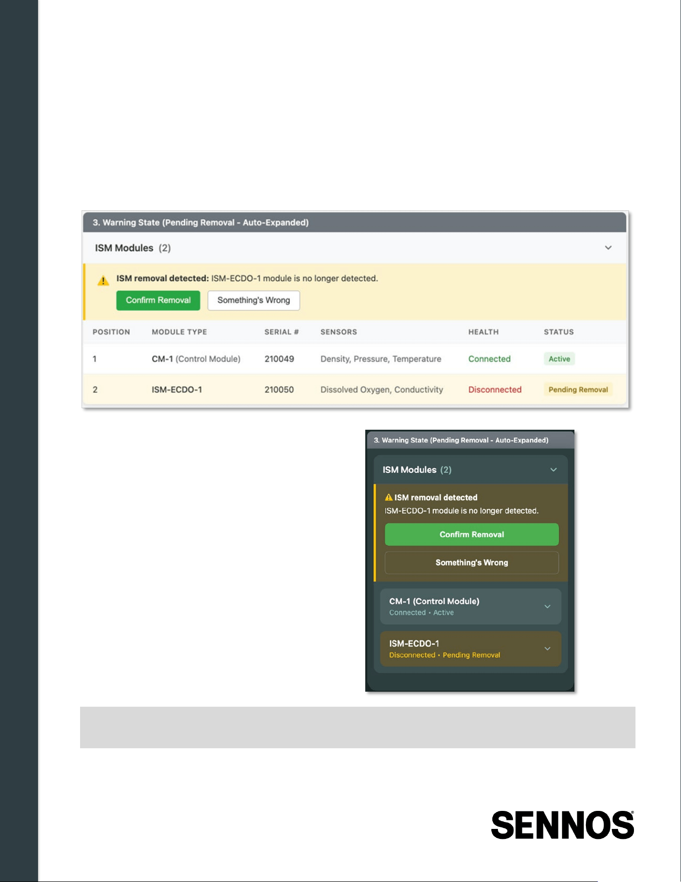
and require confirmation. On the device display, the name of the missing ISM module will appear and
the display will prompt: "Confirm removal in App."
Sennoslink will also send a notification via app, email, or SMS. Confirmation is required to update the
device configuration in Sennoslink.
Installation & Physical Setup
33 | Page
To confirm the removal in the Sennoslink app:
1. Open the Sennoslink mobile app and navigate to your device.
2. A banner will appear: "ISM removal detected."
3. Tap Confirm Removal if the removal was intentional. The device will update its configuration.
4. If you did not intentionally remove the module, tap Something's Wrong. This keeps the alert
active so you can investigate. Check that all modules are properly connected and contact
Sennos Support if the issue persists.
To confirm via email or SMS:
• Click
Confirm Removal
in the
notification email, or
• Reply
CONFIRM
to the SMS message.
Note:
If the new module does not appear in Sennoslink after 5 minutes following installation,
power cycle the device and check that all connections are secure.
Installation & Physical Setup
34 | Page
4.6.4
Installing an ISM
1. Power off the SennosM3. Press and hold the Power button until the display turns off, then wait
10 seconds for complete shutdown.
2. Hold the top assembly steady and unscrew the bottom assembly by rotating counterclockwise.
Set the bottom assembly aside.
3. Remove the existing gasket from the open connection port at the serviceable connection point.
Discard the old gasket.
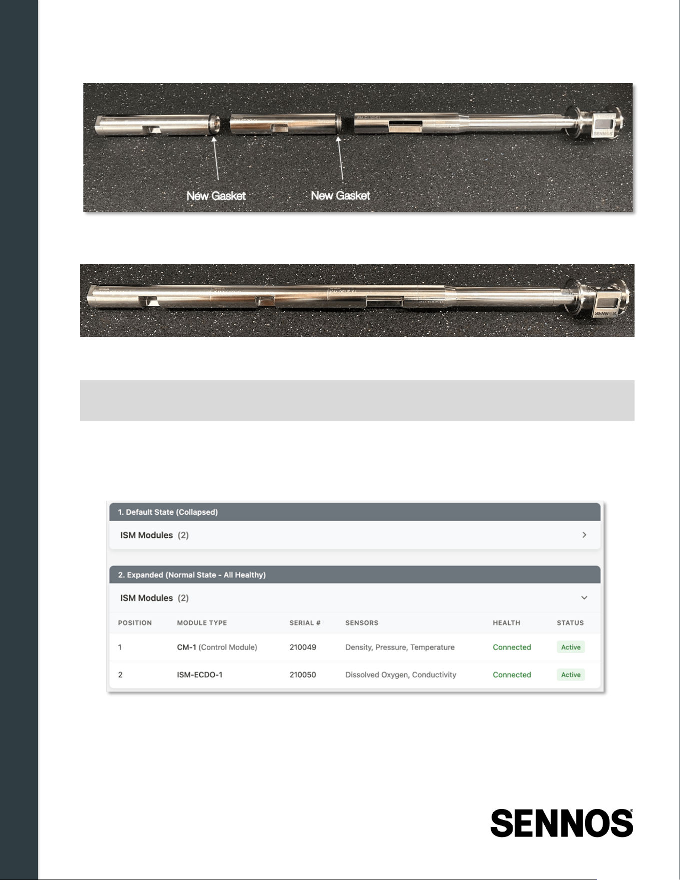
4. Take a new gasket from the ISM packaging and place it on the exposed connection port of the
upper module. Ensure the gasket is seated evenly with no gaps.
5. Align the ISM module with the exposed connection port and screw it on by rotating clockwise.
Hand-tighten until snug, do not use tools.
6. Place a second new gasket on the exposed connection port at the lower serviceable
connection point. Ensure the gasket is seated evenly with no gaps.
Note:
The following procedure uses the ISM-ECDO (Dissolved Oxygen & Conductivity)
module as an example, but the same steps apply to all ISM module types. If installing
a second ISM module, repeat the gasket and threading procedure at the next
available serviceable connection point.
Installation & Physical Setup
35 | Page
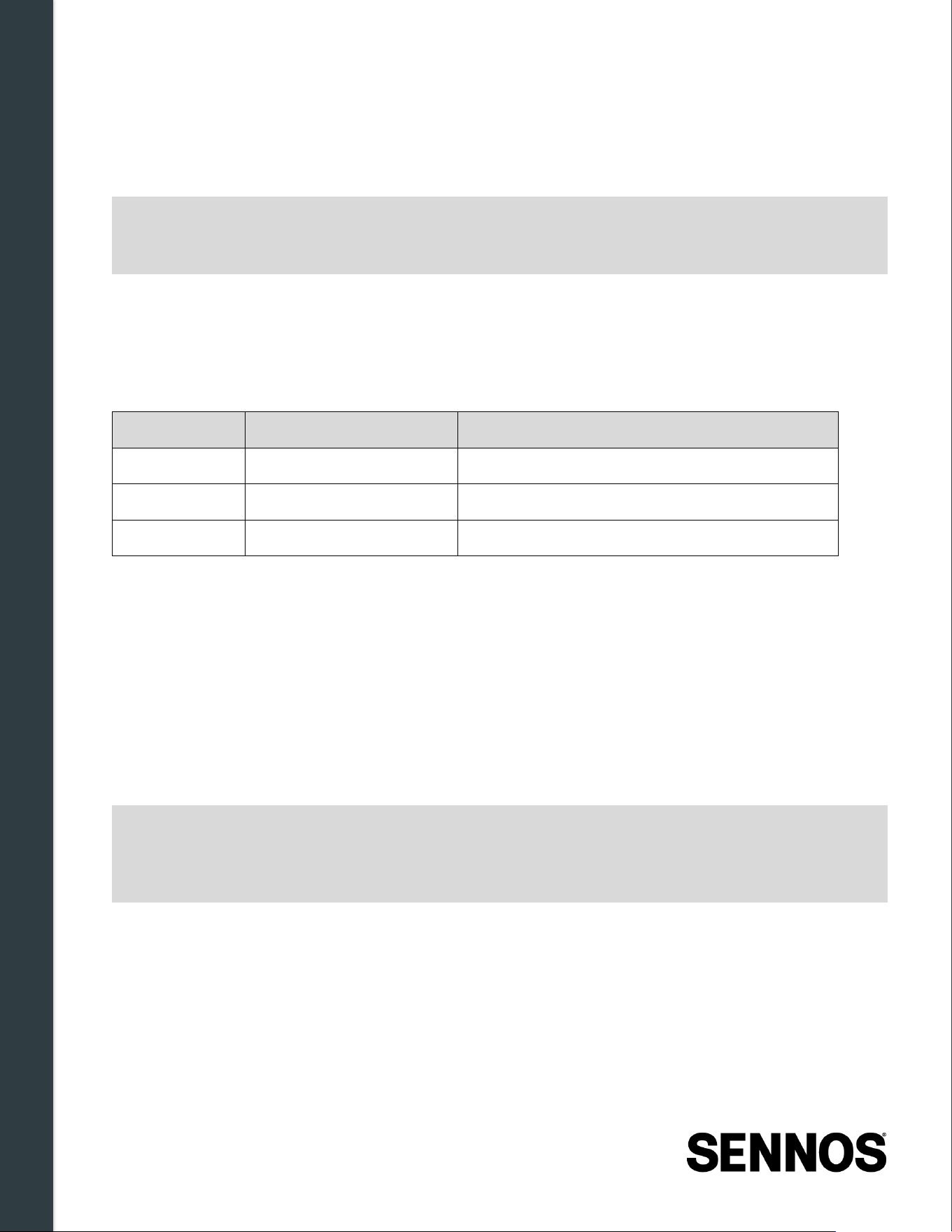
7. Align the bottom assembly with the exposed connection port, screw clockwise, and hand-
tighten until snug, do not use tools.
8. Power on the SennosM3 by pressing the Power button. The device will boot and automatically
detect the new module.
What to Expect After Installing an ISM
When the SennosM3 powers on, it will automatically detect and accept the new ISM module, no
confirmation is required. Within a few minutes, the new sensors will appear in your Sennoslink
dashboard.
Note:
Ensure all components are hand-tightened securely. Loose modules will trigger
connection warnings or measurement errors.
Installation & Physical Setup
36 | Page
4.6.5
Replacing an ISM
To replace an ISM, follow the removal procedure in Section 4.6.2 and then the installation procedure
in Section 4.6.3.
Note:
You can install the new module before confirming the removal of the old one.
Sennoslink will process both changes, the removal confirmation first, then the
automatic acceptance of the new module.
If you are returning a faulty module to Sennos, retain the packaging from the replacement ISM, it can
be used to safely ship the removed module back. Contact Sennos Support for return instructions and a
return authorization before shipping.
Quick Reference
Action
Confirmation Required?
What Happens
Install new ISM No Auto-detected and activated
Remove ISM Yes App, email, or SMS confirmation required
Replace ISM Yes (for removal only) Confirm old removal; new module auto-detected
4.6.6
Post -Replacement Confirmation
After powering on the device following any module change, confirm that no Sensor Error is displayed
on the SennosM3. This confirms the module is properly seated and electrically connected.
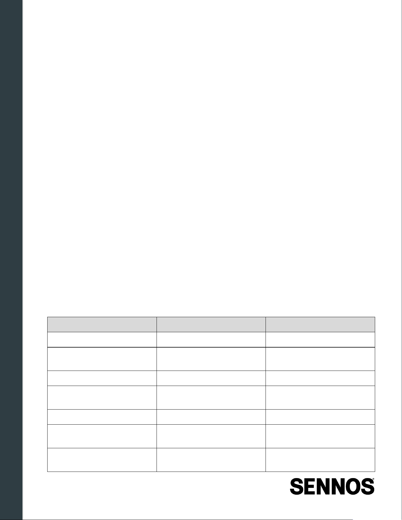
To verify the configuration in Sennoslink:
1. Open the Sennoslink mobile or web application.
2. Navigate to the Devices section and open the Device Details page for your SennosM3.
3. Confirm that the ISM Modules list matches the physical sensor stack configuration, with all
expected modules showing a status of
Connected — Active.
Note:
If a module was removed and the device detects it as missing, Sennoslink will prompt
you to confirm whether the removal was intentional. Respond to this prompt to ensure
the device configuration in Sennoslink matches the physical stack. See Section 4.6.2
for full confirmation instruction
If issues persist after replacement, such as a recurring Sensor Error after tightening and power-
cycling, or the device not appearing correctly in Sennoslink, see Section 7.1.4 - ISM Replacement
Issues for further diagnostic steps, or contact Sennos Support.
Getting Started with Sennoslink
37 | Page
5 Getting Started with Sennoslink
5.1 What is Sennoslink?
Sennoslink is Sennos' cloud-connected software system for fermentation data collection, visualization,
and analysis. When a SennosM3 is installed on a tank and connected to the internet, it securely
transmits fermentation data to the Sennos cloud, where it is accessible through the Sennoslink web
and mobile applications.
Through Sennoslink, users can:
• Start and end fermentations
• View real-time and historical fermentation data
• Monitor key fermentation parameters, including density, pH, temperature, and pressure (as
supported by installed sensor modules)
• Add manual lab readings and notes
• Configure static, dynamic, and event-based alerts
• Manage brands, tanks, devices, and users
• Review fermentation performance using dashboards, comparisons, and benchmarking tools
Sennoslink uses role-based access control, allowing different levels of visibility and control depending
on each user's assigned role. Certain features, such as company-wide settings, user management,
and advanced analytics, are restricted to administrative roles or are available only on the web
application.
5.2 Supported Platforms
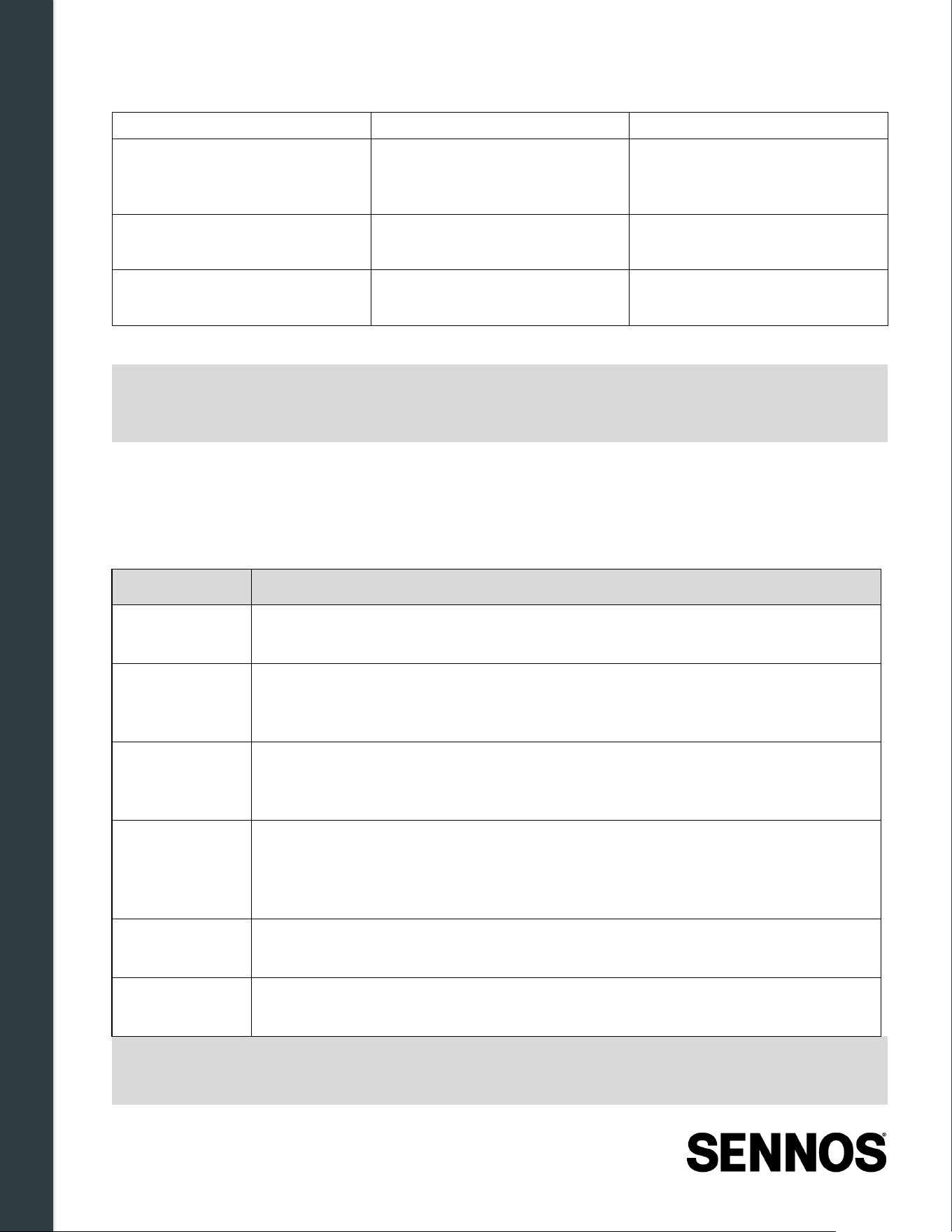
Sennoslink is accessible through both web and mobile platforms. The two platforms share core
functionality but differ in available features. The table below summarizes the primary capabilities of
each.
Feature
Web Application
Mobile Application
Start and end fermentations Supported Supported
Configure & manage device Wi-
Fi
Not available
Required
for initial Wi-Fi setup
of the SennosM3
Add manual lab data and notes Supported Supported
Monitor real-time sensor
readings
Supported Supported
Manage users, contacts & roles Supported (Admin only) Not available
Configure alerts, benchmarks &
KPIs
Supported Not available
Manage tanks, brands &
locations
Supported (add & manage) Basic brand details only —
alerts, KPIs, graphs, and
Getting Started with Sennoslink
38 | Page
benchmarks require web
Manage devices Manage only — devices are
provisioned by Sennos and
appear automatically
Manage only
Company Profile & tenant
settings
Supported (Admin only) Not available
View historical fermentation
data
Supported Supported
Note:
The mobile application is required for Wi-Fi configuration of the SennosM3 and for
certain device-level setup workflows. Some administrative and advanced configuration
features are available only through the web application.
5.3 User Roles & Permissions
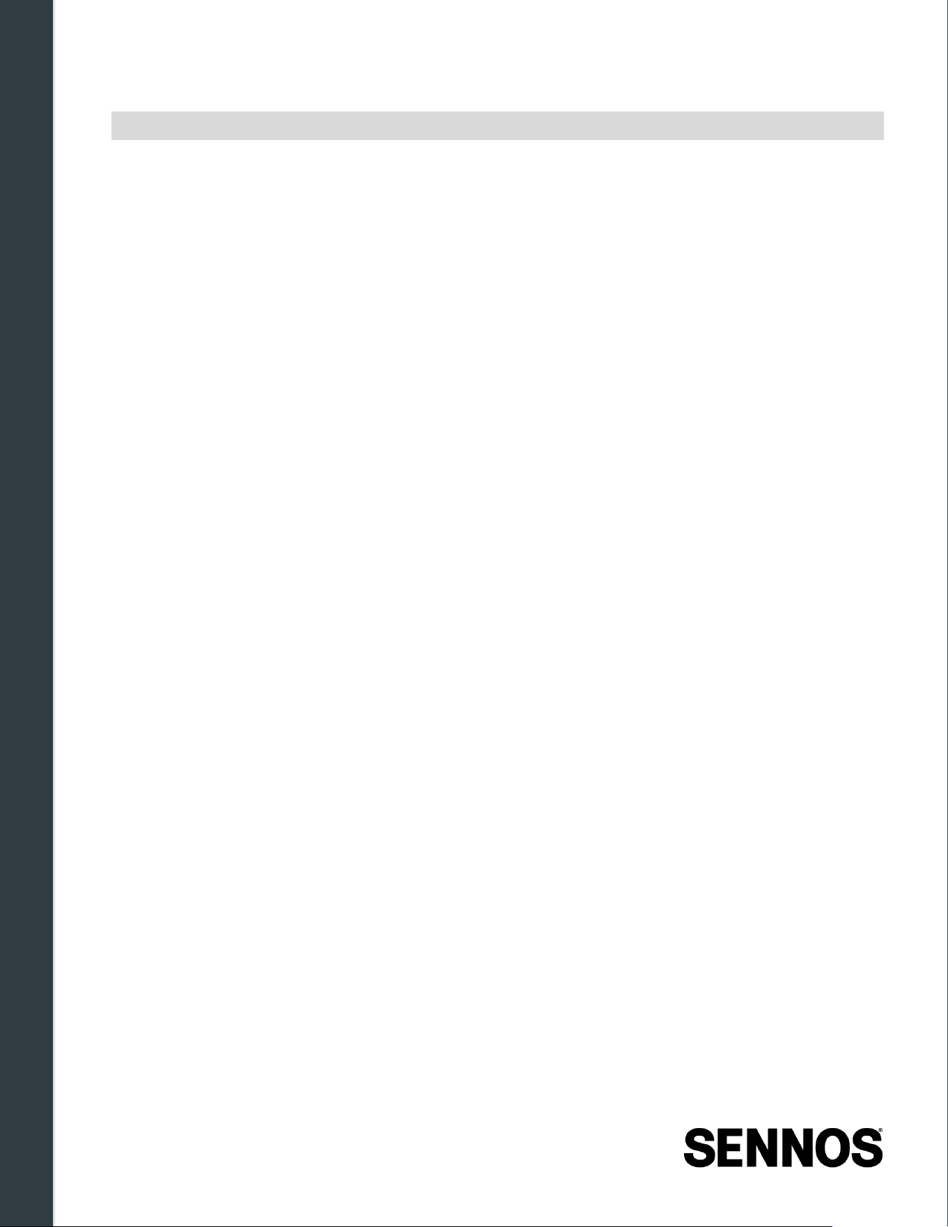
Sennoslink uses role-based access control to manage what actions users can perform. Roles are
assigned when users are invited and can be modified by account administrators.
Role
Access & Capabilities
Viewer
Can view all dashboard pages except Manage Users and Company Profile.
Cannot start or end fermentations, control devices, or modify settings.
Operator
Can view all dashboard pages except Manage Users. Can start, pause, resume,
and end fermentations. Can control devices and add manual readings. Cannot
manage users or modify company-wide settings.
Admin
Includes all Operator permissions. Can invite users and contacts, assign and
modify roles, and access and modify the Company Profile page, including
company-wide settings.
Admin and
Data Access
Includes all Admin permissions. Additionally grants access to the Sennos API for
programmatic data retrieval. This role is typically used for system integrations.
Contact Sennos Support to enable, this cannot be assigned by an account
administrator.
Viewer and
Data Access
Includes all Viewer permissions, plus access to the Sennos API for data
retrieval. Contact Sennos Support to enable.
Disabled
User account is deactivated. The user can no longer log in to Sennoslink.
Administrators can disable users directly from the Manage Users page.
Note:
Data access roles allow users to retrieve fermentation data programmatically via the
Sennos API. These roles require Sennos Support to assign and cannot be granted by
an account administrator. For more information on data access and API usage, contact
Getting Started with Sennoslink
39 | Page
Sennos Support for assistance.
Getting Started with Sennoslink
40 | Page
5.3.1
Contacts (Non -User Access)
Contacts can be added to the system to receive alert notifications without being granted access to
Sennoslink. Contacts are commonly used for operational or support personnel, such as cellar staff or
IT contacts, who need alert notifications but do not require system access.
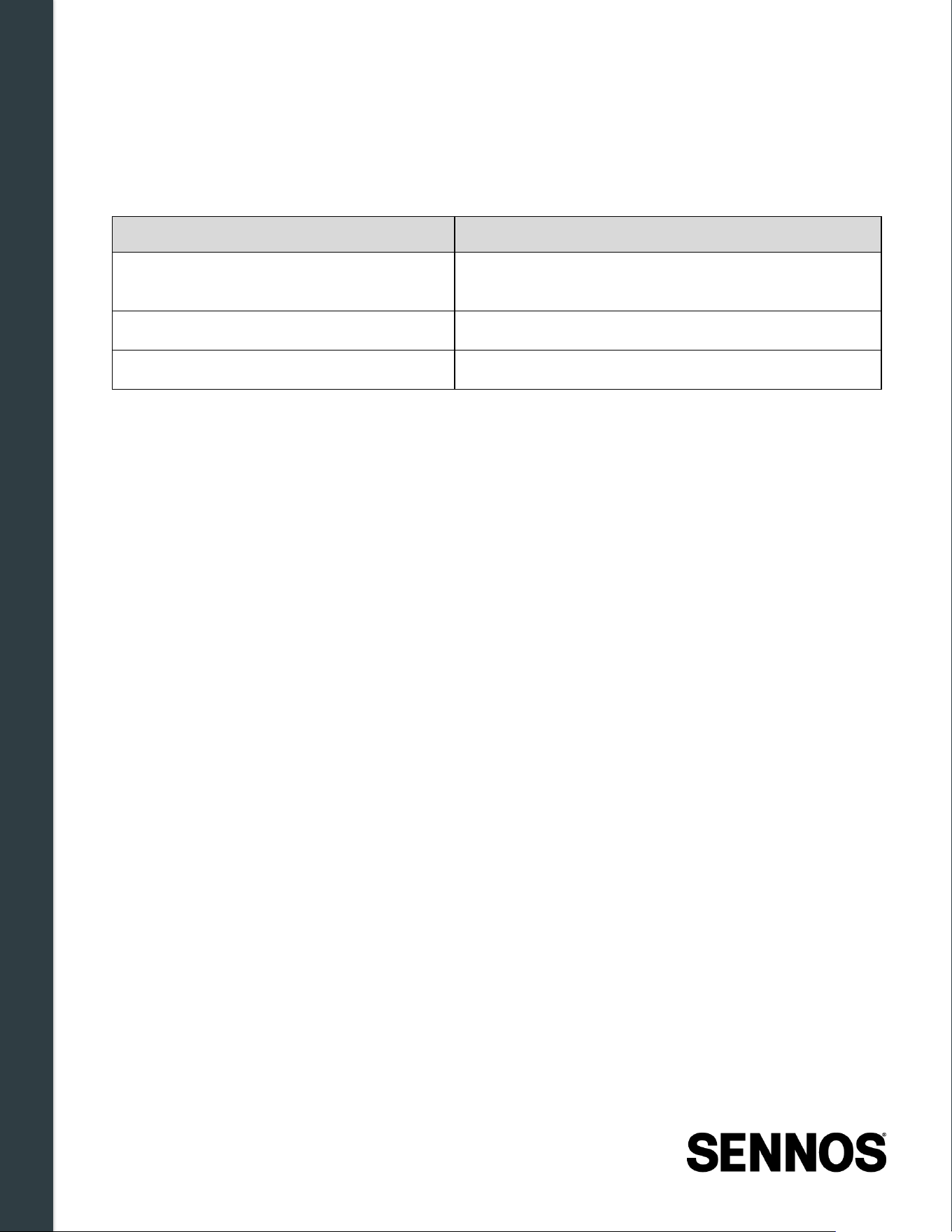
Contacts can
Contacts cannot
Receive alert notifications via email or text
message
Log in to Sennoslink (web or mobile)
View fermentation data
Modify any system settings
5.4 Account Registration & Login
Access to Sennoslink requires an active user account associated with your organization.
5.4.1
Account Invitation
Accounts are created through an invitation process:
• First account setup: When your organization is first onboarded to Sennoslink, Sennos
Support sends an invitation to the designated primary contact.
• Subsequent users: Once the first Admin account is established, that administrator can invite
additional team members directly from the Manage Users page in Sennoslink — no Sennos
Support involvement is required.
• Data access roles: Exception — assigning Admin and Data Access or Viewer and Data
Access roles requires Sennos Support. Administrators cannot grant these roles themselves.
The invitation email contains a secure activation link valid for 24 hours. If the link has expired or the
email cannot be located (check spam folders), contact Sennos Support to request a new invitation.
Getting Started with Sennoslink
41 | Page
5.4.2
Account Activation
To activate a Sennoslink account:
1. Open the invitation email and select the activation link.
2. Follow the on-screen instructions to set a password and confirm account details.
3. Complete the activation process to enable access.
Note:
The activation link opens the Sennoslink web application — this is true even if you
open the email on a mobile device (it will open in a mobile browser, not the Sennoslink
mobile app). Once your account is activated, download the Sennoslink mobile app
separately and log in using your new credentials.
5.4.3
Logging In
After activation, log in at the Sennoslink login page using your registered email address and password.
The same credentials are used across both the web application and the Sennoslink mobile app.
Users are encouraged to bookmark the login page for convenient future access.
5.4.4
Account Assistance
If you experience issues with account access, activation, or login:
• Verify the invitation email has not expired (links are valid for 24 hours)
• Confirm correct email address and password
• Check spam or junk folders for the invitation email
• Contact Sennos Support to resend an invitation or resolve access issues
5.5 Navigating the Sennoslink Interface
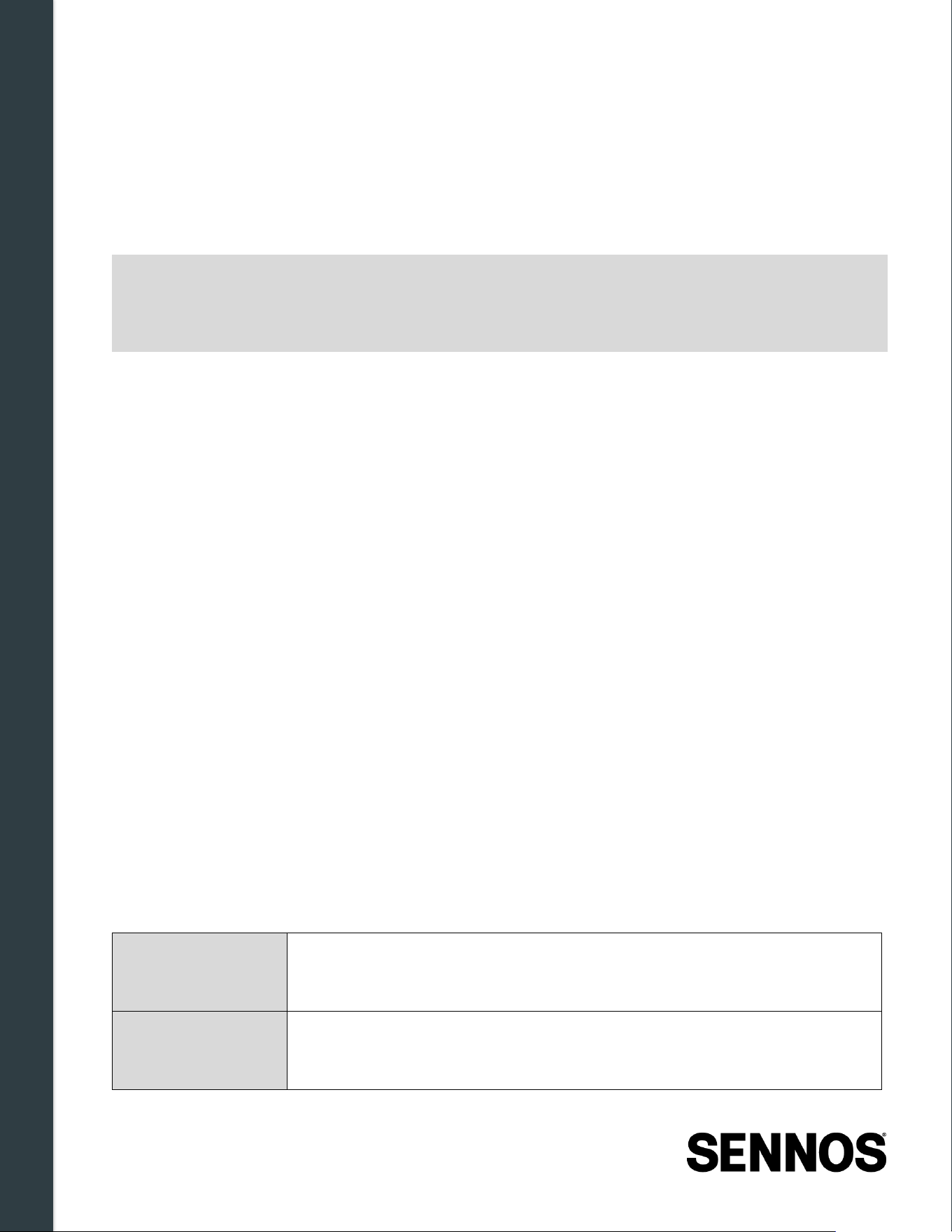
Sennoslink is organized into distinct sections accessible through the navigation menu. The web and
mobile applications share the same core sections but differ in layout and available features, the web
application uses a left-hand sidebar while the mobile app uses a bottom navigation bar.
Navigation between sections does not interrupt active fermentations or data collection. The following is
a high-level overview of each section. For detailed guidance on using specific features, refer to the
Sennoslink user guide.
Dashboard
Primary operational overview. Shows active fermentations, current sensor
readings, alert status, device connectivity, and recently completed
fermentations.
Fermentations
Access all active, completed, and historical fermentations. Start and end
fermentations, view data and graphs, add manual readings, and compare
batches.
Getting Started with Sennoslink
42 | Page
Devices
View status of all connected SennosM3 devices, including tank assignment,
Wi-Fi connectivity, power status, and battery level.
Brands
Create and manage brands, define benchmarks, configure alerts, and
review brand-level analytics. Full brand analytics (KPIs, benchmarks,
graphs) are available on web only.
Tanks
Add tanks, assign devices to tanks, and manage tank metadata.
Locations
Define fermentation production locations associated with tanks and
fermentations.
Manage Users
(Admin, web only)
Invite users, assign roles, and manage user access levels.
Company Profile
(Admin, web only)
Company-wide configuration including compensation preferences, KPI
category management, and in-house yeast culture definitions.
My Profile
Manage personal account settings: contact information, password, time
zone and unit preferences, notification preferences, and contacts.
Help
Access support contact information and links to current documentation,
including the latest user guides and reference materials.
5.5.1
Page Interaction and Data Display
Across the Sennoslink interface:
• Graphs can be expanded and minimized
• Data tables can be filtered by time interval or data type
• Alerts and thresholds can be reviewed and adjusted where permitted by role
• Navigation between pages does not interrupt data collection or device operation
For detailed instructions on using each section, refer to the Sennoslink Platform Documentation.
Getting Started with Sennoslink
43 | Page
5.6 Managing Devices in Sennoslink
The Devices section of Sennoslink provides centralized visibility into all SennosM3 devices associated
with an account. From here, users can monitor device status, confirm tank assignments, and verify
readiness for fermentation monitoring.
5.6.1
Devices Page Overview
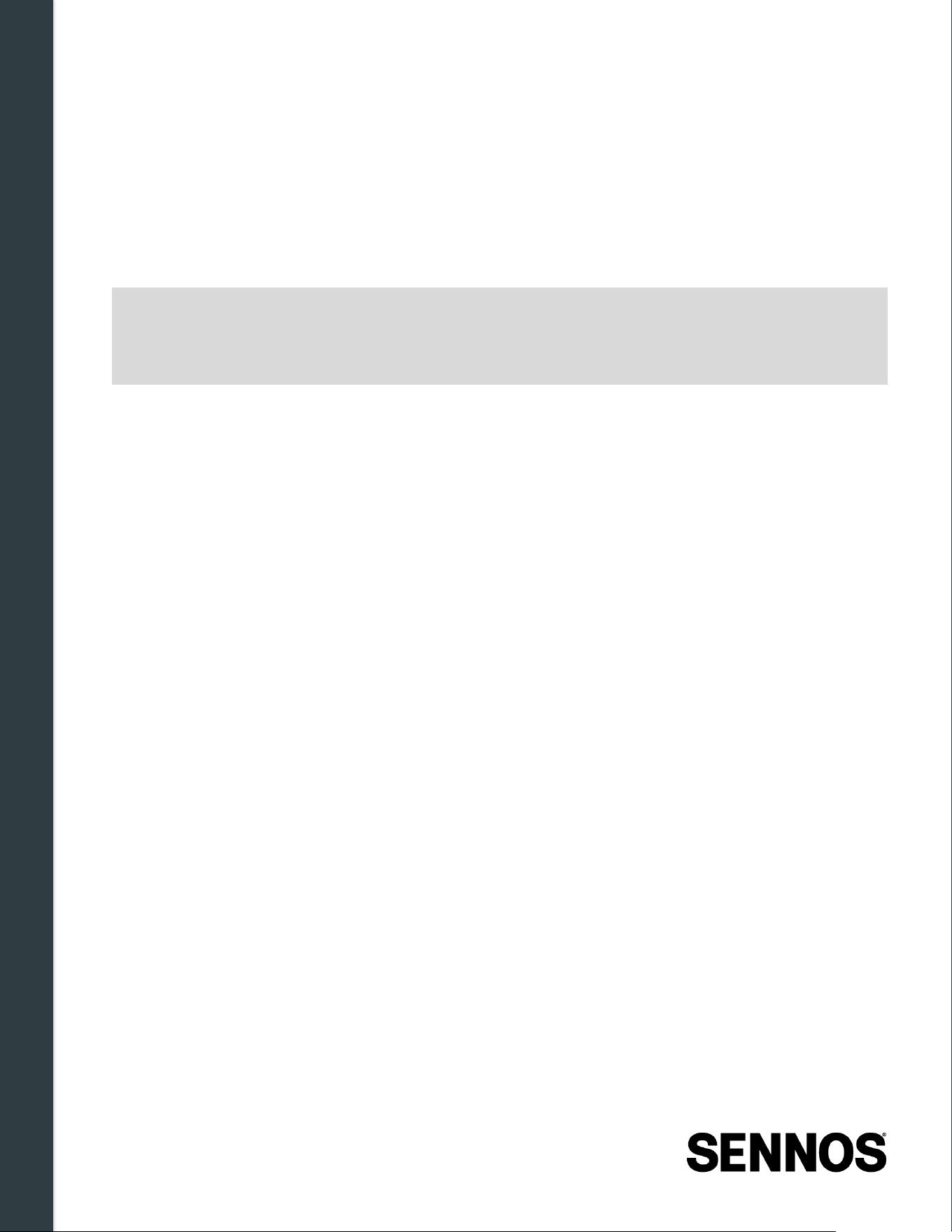
The Devices page displays a list of all SennosM3 units
registered to the account. For each device, users can
view:
• Device name
• Current tank assignment
• Wi-Fi connection status
• Battery level and power status
Note:
The Devices page is for monitoring
and administrative awareness.
Physical installation, Wi-Fi setup, and
cleaning procedures are covered in
Sections 3, 3.4, and 6 respectively.
Figure 5-1. Device Details
5.6.2
Device Assignment to Tanks
Before a fermentation can be started, the SennosM3 must be associated with a tank in Sennoslink.
Each device can be assigned to one tank at a time.
Tank assignment can be done in either of the following ways:
• Ahead of time: Assign the device to a tank from the Devices page in Sennoslink before
beginning a fermentation.
• At fermentation start: Select the tank directly from the fermentation start screen in the
Sennoslink mobile app.
Note:
The Devices page is for monitoring and administrative awareness. Physical installation,
Wi-Fi setup, and cleaning procedures are covered in Sections 3, 3.4, and 6
respectively.
Getting Started with Sennoslink
44 | Page
5.6.3
Power Readiness Before Fermentation
For reliable fermentation monitoring, the SennosM3 should be fully charged to 100% before
installation on a vessel. There is a meaningful difference in runtime between 99% and 100% charge.
Battery level is shown as a percentage in the Sennoslink mobile app (on the device detail page) and
as a bar indicator in the web application. The device display shows a charge icon when connected to
external power.
Note:
For long or critical fermentations, Sennos recommends connecting the device to
continuous external power during the fermentation. A Sennos battery pack is also
available as an alternative to wall power, contact your Customer Engagement Manager
or Sennos Support for details.
5.6.4
Device Status Awareness
The Devices page provides at-a-glance visibility into potential issues without requiring physical access
to the hardware, including:
• Loss of Wi-Fi connectivity
• Low battery — alerts can be configured in Sennoslink to notify users when battery reaches low
(~70%) or critical (~5–10%) levels
• Devices not yet assigned to a tank
This view supports proactive management across multiple tanks and locations.
Cleaning, Handling & Storage
45 | Page
6 Cleaning, Handling & Storage
Proper cleaning, handling, and storage of the SennosM3 are essential for accurate measurements,
sensor performance, and device longevity. The SennosM3 is designed for use in wet fermentation
environments, but must be cleaned and stored according to the procedures in this chapter.
Clean the device after removal from a fermenter and before storage or reinstallation. Sanitize the
device as the final step before installing it on a vessel, cleaning and sanitizing are separate steps.
Cleaning procedures apply to the sensor assembly and fluid pass-through port only;
the display and
control module must not be submerged.
When the SennosM3 is not installed on a fermenter, the pH and dissolved oxygen (DO) sensors
must be kept hydrated. Use the Sennos storage reservoir to maintain hydration during storage
between fermentations.
6.1 Cleaning Safety Guidelines
The following safety guidelines apply to all cleaning and maintenance activities involving the
SennosM3:
Parameter
Limit / Requirement
Maximum device operating
temperature
55°C (131°F)
Maximum cleaning solution
temperature
60°C (140°F)
Approved cleaners Non-caustic cleaners only
Recommended cleaners
Cell-R-Mastr or PBW
Submersion Sensor assembly only, do not submerge the display or control
module
Device state during cleaning Powered off
Alternative cleaning agents
Contact Sennos Support or your Customer Engagement Manager
before using any cleaner not listed above
Note:
The device operating limit (55°C) and the maximum cleaning solution temperature
(60°C) are different values. The solution may be warmer than the device limit, but
contact with the device should remain within the device's rated operating range. Do not
expose the device to prolonged heat above 55°C.
WARNING:
If the SennosM3 is used or cleaned in a manner not specified by the manufacturer,
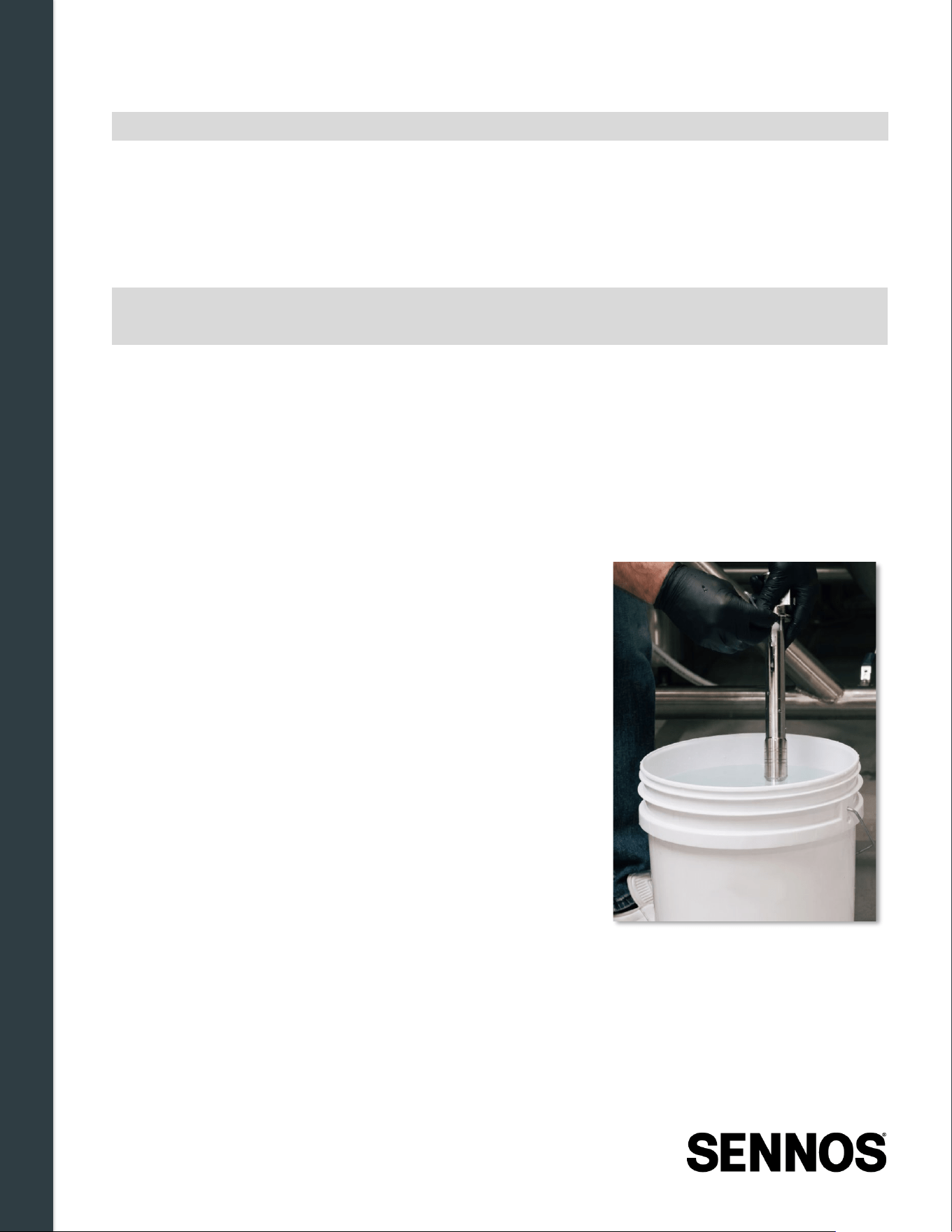
Cleaning, Handling & Storage
46 | Page
the protection provided by the equipment may be impaired.
6.2 Cleaning Procedures
Clean the SennosM3 after every removal from a fermentation vessel. If the device will be reinstalled
on another fermenter the same day, proceed directly to sanitization after cleaning. If it will be stored,
follow the storage procedures in Section 6.4.
Note:
Clean at end of use. Sanitize before reinstallation. These are separate steps — a clean
device still requires sanitizing before it is installed on a vessel.
6.2.1
Preparation
Before beginning the cleaning process:
• Power off the SennosM3 before beginning cleaning.
• Remove the device from the fermentation vessel.
• Do not submerge the display screen or control module housing at any point during cleaning.
6.2.2
Cleaning Steps
1. Rinse the device. Rinse the SennosM3 to remove
visible debris before soaking.
2. Submerge the sensor assembly only. Place the
sensor assembly in the prepared cleaning solution. Do
not submerge the display or control module housing.
3. Clean sensor openings and the fluid pass -through
port. Using the provided cleaning brush, gently scrub all
sensor frame openings and clean the fluid pass-through
port thoroughly.
4. Rinse thoro ughly. Rinse the sensor assembly with
warm water to remove all cleaning solution residue.
5. Dry external surfaces. Use the provided cleaning cloth
to dry external components.
Figure 6 -1: Cleaning the M3 -
Proper Submerging Depth
Cleaning, Handling & Storage
47 | Page
6.2.3
Post -Cleaning Handling
After cleaning:
• If reinstalling the same day: Sanitize the device using your standard fermentation production
sanitization procedure, then proceed to installation.
• If storing: Apply the storage reservoir to protect the pH and DO sensors, then follow the
storage procedures in Section 6.4.
6.3 Sensor Care & Storage Reservoir Usage
Proper sensor care is critical to ensuring accurate measurements, maintaining sensor longevity, and
preventing damage to the SennosM3 device. Special attention must be given to the pH and dissolved
oxygen (DO) sensors, both of which require hydration when the device is not installed on a
fermentation vessel.
6.3.1
pH & DO Sensor Hydration Requirements
The pH & DO sensor must remain hydrated whenever the SennosM3 is removed from a fermenter and
will not be installed on another fermenter the same day. Failure to keep the pH sensor hydrated may
result in degraded sensor performance or permanent damage.
Hydration is maintained using the Sennos storage reservoir , which contains a hydration pad
designed specifically for the pH sensor.
6.3.2
Applying the Storage Reservoir
Follow the steps below to apply the storage reservoir:
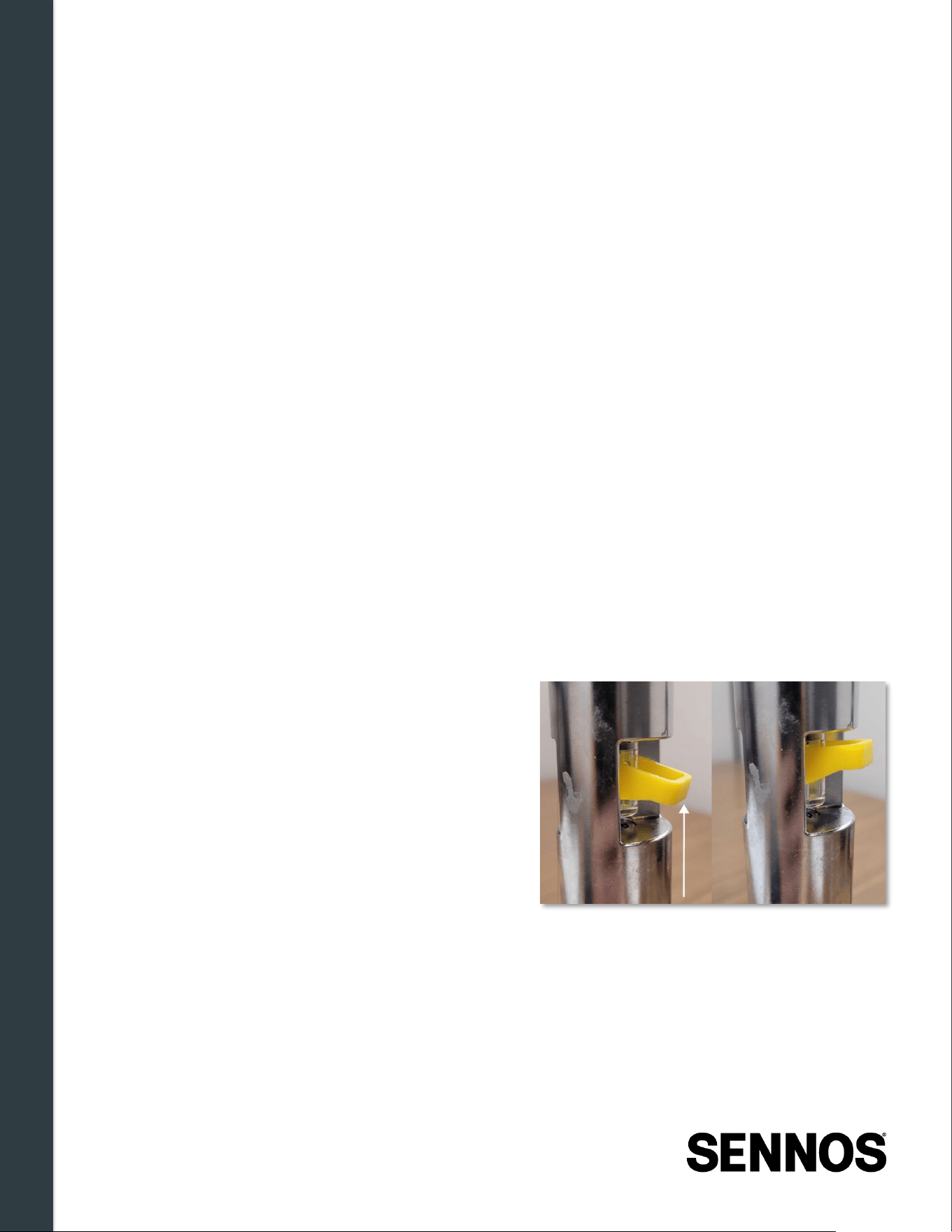
1. Ensure the pH sensor is clean and free of
debris.
2. Remove any protective covers from the
storage reservoir.
3. Insert the storage reservoir into the sensor
opening and press the lever down to secure it
in place.
4. Verify the reservoir is fully seated and the
sensors are covered.
Figure 6 -2: Securing Storage Reservoir
The pH sensor is located in the sensor frame opening closest to the display screen.
6.3.3
Storage Considerations
The SennosM3 may be stored using one of the following methods:
Storage Method 1: Storage Reservoir (Dry Storage)
Cleaning, Handling & Storage
48 | Page
Once the storage reservoir is applied:
• The SennosM3 may be optionally charged using the provided power cable.
• Store the device safely on a shelf or in its storage case until the next use.
• Ensure the storage reservoir remains in place for the duration of storage.
Storage Method 2: Sanitizer Storage (Wet Storage)
• Place the SennosM3 in a bucket of sanitizer.
• Ensure the pH and DO sensors are fully submerged and covered by sanitizer at all times.
• Do not submerge the Tank Mount or display screen. These components must remain clear of
fluid.
6.3.4
Sensor Handling Best Practices
• Always clean the sensor assembly according to the documented cleaning procedures before
applying the storage reservoir.
• Avoid allowing the pH and DO sensors to dry out between fermentations.
• Replace storage reservoirs as needed to ensure proper hydration.
6.4 Storage Between Fermentations
When the SennosM3 is removed from a fermenter and will not be installed on another fermentation the
same day, proper storage procedures must be followed to protect the sensors, particularly the pH
sensor, and maintain device readiness for future use.
The pH and dissolved oxygen (DO) sensors must remain hydrated whenever the device is not actively
installed on a fermenter. This is accomplished using the Sennos storage reservoir provided with the
system. Failure to keep the sensors hydrated may negatively impact sensor performance and
longevity.
Before storage, ensure the SennosM3 has been cleaned in accordance with the cleaning procedures
outlined in Section 6.2. Once cleaning is complete and the device is no longer in use, apply the
storage reservoir as described in Section 6.3.
6.4.1
Applying the Storage Reservoir for Storage
To prepare the device for storage:
• Ensure the pH sensor is clean and free of debris.
• Remove any protective covers from the storage reservoir.
• Insert the storage reservoir into the sensor opening and press the lever down to secure it in
place. Verify the reservoir is fully seated and the pH and DO sensors are covered.
• Do not apply adhesive directly to the sensor surface.
Note:
The pH sensor is located in the sensor frame opening closest to the display screen.
Once the storage reservoir is applied, the device may be optionally connected to power using the
provided power cable. Store the device on a shelf or in an appropriate storage case until next use.
Troubleshooting & Support
49 | Page
These storage steps help ensure the SennosM3 remains in proper working condition and ready for
accurate monitoring during subsequent fermentations.
6.5 Cleaning & Maintenance Warnings
Failure to follow approved cleaning and maintenance procedures may result in inaccurate readings,
equipment damage, or reduced sensor lifespan.
Topic
Warning
Temperature Do not exceed 55°C (131°F) device operating temperature during cleaning.
Maximum cleaning solution temperature is 60°C (140°F).
Cleaning agents Use only approved non-caustic cleaners. Contact Sennos Support or your
Customer Engagement Manager before using any alternative cleaning
chemical.
Submersion The display screen and control module must never be submerged. Only the
sensor assembly may be submerged during cleaning.
Sensor protection
Use only the provided cleaning brush on sensor frame openings and the fluid
pass-through port. Avoid mechanical stress or impact to sensor openings.
pH and DO
sensor hydration
The pH and DO sensors must remain hydrated whenever the device is
removed from a fermenter and not immediately reinstalled. Always use the
storage reservoir during storage between fermentations.
Module integrity Ensure all modules are fully tightened before installation. A
Sensor Error
screen indicates a module is not properly seated — resolve this before
installing the device on a tank.
General use
The SennosM3 is intended for indoor use only. Use the device only as
described in this guide. Use outside of specified procedures may impair the
protection provided by the equipment.
7 Troubleshooting & Support
This chapter provides guidance for resolving common hardware and software issues encountered with
the SennosM3 system. Work through the relevant section below before contacting Sennos Support —
most issues can be resolved without escalation.
If an issue cannot be resolved using the steps below, escalation paths and contact information are
provided in Sections 7.5 and 7.6.
Issue Quick Reference
Use the table below to jump directly to the relevant troubleshooting section.
Symptom
Go to
Troubleshooting & Support
50 | Page
Device Will Not Power On Section 7.2.1
Device Enters Sleep Mode or Battery is Low Section 7.2.2
Sensor Error / Check Modules Displayed Section 7.2.3
ISM Replacement Issues Section 7.2.4
Inaccurate or Missing Sensor Readings
Section 7.2.5
pH or DO Sensor Issues Section 7.2.6
Cleaning-Related Issues Section 7.2.7
No Networks Appearing in Wi-Fi Manager (Bluetooth Check)
Section 7.3.1
Network Appears but Device Cannot Connect Section 7.3.2
Network Is Saved but Device Won’t Reconnect Section 7.3.3
Connected to Wi-Fi but not to Sennos Cloud Section 7.3.4
Firewall Configuration Issues Section 7.3.5
Sending Logs to Support Section 7.3.6
Device Not Appearing in Sennoslink Section 7.4.1
User Access or Permission Issues Section 7.4.2
Need to Contact Support or Escalate Section 7.5 / 7.6
7.1 Troubleshooting Tools
The Sennoslink mobile application includes a set of built-in diagnostic tools available on the Device
Details page. These tools are designed to help identify and resolve connectivity and device issues.
Under normal operation, these tools are not needed, they are intended for use when something is not
working as expected.
To access the troubleshooting tools, open the Sennoslink mobile app, navigate to the Devices
section, and tap the device card for your SennosM3 to open the
Device Details page.
Note:
All tools in this section are available in the Sennoslink mobile app only and are not
accessible from the web application.
7.1.1
Bluetooth Check
The Bluetooth Check tool verifies that your phone and the SennosM3 are correctly configured for
Bluetooth communication. Because Sennoslink communicates with the SennosM3 over Bluetooth to
perform several key functions, including Wi-Fi setup and log retrieval, Bluetooth must be enabled and

Troubleshooting & Support
51 | Page
permitted on your phone for these features to work.
Running a Bluetooth Check will confirm:
• Whether your phone's Bluetooth is turned on
• Whether the Sennoslink app has been granted Bluetooth permissions on your phone
• Whether the SennosM3 is detectable and advertising a Bluetooth signal
If any of these checks fail, the tool will identify the specific point of failure and provide on-screen
instructions for resolving it, including OS-specific steps for enabling Bluetooth or granting app
permissions on iOS and Android.
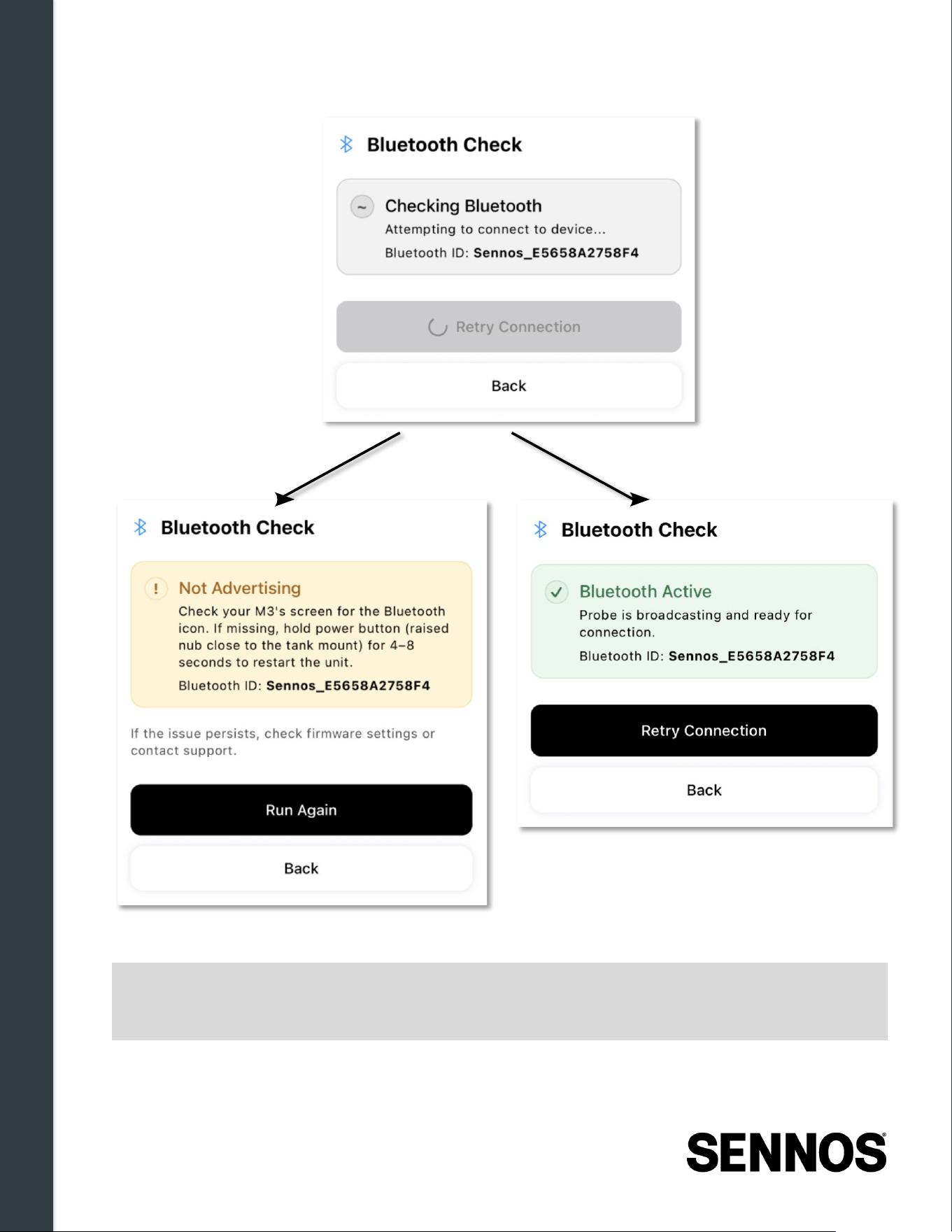
Troubleshooting & Support
52 | Page
Figure 7 -1: Bluetooth Check
Note:
You must be within Bluetooth range of the SennosM3 for the tool to complete the full
check. If the device cannot be detected, the tool will indicate that the device may be out
of range or that Bluetooth has not been enabled on the device.
When to use this tool:
Use the Bluetooth Check as your first diagnostic step when no Wi-Fi networks appear in Wi-Fi
Troubleshooting & Support
53 | Page
Manager, or any time you suspect a Bluetooth connectivity issue between your phone and the
SennosM3.
7.1.2
Bluetooth Bridge
Bluetooth Bridge allows the Sennoslink mobile app to communicate directly with the SennosM3 using
your phone as a bridge, even when the device is not connected to Wi-Fi. This enables remote
commands and configuration to be sent to the device through your phone's connection.
This tool is useful when:
• The SennosM3 has lost its Wi-Fi connection and cannot be reached through the cloud
• You need to send commands or configuration updates to the device without an active Wi-Fi
connection
Note:
You must be within Bluetooth range of the SennosM3 to use Bluetooth Bridge.
7.1.3
Send Logs to Support
The Send Logs to Support tool transmits diagnostic log data from the SennosM3 directly to the
Sennos support team. Logs provide Sennos Support with a record of device activity and error states
that may not be visible from the app or device display alone.
Figure 7 -2: Send Logs to Support
Before or after sending logs, contact Sennos Support directly to describe what you are experiencing
and what troubleshooting steps you have already taken. Logs provide the device-side picture, your
description provides the context needed to resolve the issue efficiently. See Section 7.5 for support
contact information.
Note:
You must be within Bluetooth range of the SennosM3 to send logs. This tool is only
available in the Sennoslink mobile app.
When to use this tool:
Send logs when directed to by Sennos Support, or when you have worked through the relevant
troubleshooting steps in this section and the issue remains unresolved.
7.2 Hardware Issues
The following issues relate to the physical SennosM3 device, sensor modules, power, and installation.
7.2.1
Device Does Not Power On
Troubleshooting & Support
54 | Page
• Confirm the device is fully charged or connected to external power using the provided power
cable and adapter.
• Verify the power cable is securely attached to the magnetic charging port on the control
module.
• Use only the provided 5 V, 2 A power adapter. Using an incompatible adapter may prevent
charging or power-on.
• Press and hold the power button (the button with the raised tactile indicator, closest to the
tank when installed) for 4–5 seconds. The Sennos logo will appear first, followed by the device
serial number once fully booted.
Note:
Battery level is shown as a percentage in the Sennoslink mobile app (device detail
page). Charge the device to 100% before beginning a fermentation — there is a
meaningful runtime difference between 99% and 100%.
7.2.2
Device Enters Sleep Mode or Battery Is Low
The SennosM3 enters power-saving mode between sampling cycles when running on battery. This is
normal behavior — the device continues monitoring in this state.
• To wake the display, press the Select button (the button without the raised tactile indicator)
once. Do not press and hold the power button — this will power the device off completely.
• Connecting the power cable keeps the device from returning to sleep once awake, but does
not automatically wake it.
• For long or critical fermentations, connect the device to continuous external power. A Sennos
battery pack is also available, contact your Customer Engagement Manager or Sennos
Support for details.
• Battery alerts can be configured in Sennoslink to notify you when the battery reaches a low
(~70%) or critical (~5–10%) threshold.
Troubleshooting & Support
55 | Page
7.2.3
Sensor Error — Check Modules
If the display shows a Sensor Error screen with a Check Modules message and a diagram
highlighting the affected module, one or more sensor modules are not fully tightened.
1. Power off the SennosM3.
2. Inspect all module connections and hand-tighten any that are loose.
3. Power the device back on. A power cycle is required to clear the error — tightening alone will
not update the display.
4. Confirm the Sensor Error screen no longer appears before proceeding with installation.
WARNING:
Do not install the device on a fermentation vessel while a Sensor Error is displayed.
Loose modules will produce inaccurate readings or device errors.
7.2.4
ISM Replacement Issues
Sensor Error Displayed After Replacement
• Ensure all modules are fully tightened
• Verify gaskets are correctly installed and not pinched or misaligned
• Power off, re-tighten all connections, and power on again — a power cycle is required to clear
the error
Note:
If a Sensor Error persists after re-tightening and power cycling, refer to Section 7 –
Troubleshooting & Support before proceeding. If the issue cannot be resolved through
troubleshooting, contact Sennos Support for assistance.
Device Not Appearing Correctly in Sennoslink After Replacement
• Confirm module replacement was verified on the device display (no Sensor Error shown)
• Verify the device has reconnected to Wi-Fi
• Check the Devices page in Sennoslink for status errors
7.2.5
Inaccurate or Missing Sensor Readings
• Confirm the device is installed in a compatible 1.5-inch tri-clamp port with the correct
orientation: display sideways, control buttons above the display.
• Ensure the fermenter port and sensor openings are free of debris before installation.
• Verify no Sensor Error is displayed — a loose module will produce missing or incorrect
readings.
• Confirm the device has not exceeded its environmental operating limits (see Section 8).
• After removal from a tank, clean the sensor assembly according to the procedures in Section
6.2 before storage or reinstallation.

Troubleshooting & Support
56 | Page
Troubleshooting & Support
57 | Page
7.2.6
pH and DO Sensor Issues
• Sensor reads incorrectly or degrades over time: The pH and dissolved oxygen (DO)
sensors must remain hydrated whenever the device is not installed on an active fermenter.
Allowing either sensor to dry out causes degraded performance or permanent damage.
• Sensor dried ou t during storage: Apply the storage reservoir immediately. Allow the sensor
to rehydrate before the next fermentation. If accuracy remains poor after rehydration, contact
Sennos Support — sensor replacement may be required.
• Storage reservoir not seated cor rectly: Refer to Section 6.3.2 for the correct reservoir
installation procedure. The lever must be fully pressed to seat the reservoir against the sensor.
• Unsure which sensor is pH vs. DO: Refer to the sensor identification diagram in Section
6.3.1. Note: color/shape coding for sensor identification is planned for a future hardware
revision.
7.2.7
Cleaning -Related Issues
• Sensor damage after cleaning: Verify the cleaning solution temperature did not exceed 60°C
(140°F), and that no caustic cleaners were used. See Section 6.2 for approved procedures.
• Display or control module exposed to liquid: The display and control module must not be
submerged at any point during cleaning. Only the sensor assembly may be submerged. If the
display was submerged, contact Sennos Support before reusing the device.
• Residue remaining after cleaning: Rinse the sensor assembly thoroughly with warm water
after soaking. Use the provided cleaning brush on all sensor frame openings and the fluid
pass-through port.
• Using an alternative cleani ng agent: Contact Sennos Support or your Customer
Engagement Manager before using any cleaner not listed in Section 6.1. Include the product's
Safety Data Sheet (SDS) when submitting a request for approval.
7.3 Wi -Fi Connectivity Issues
Wi-Fi connection problems are among the most common issues encountered during SennosM3 setup.
Work through the steps below in order; each section builds on the previous one.
Note:
Wi-Fi configuration is performed through the Sennoslink mobile app. Before
troubleshooting, ensure the Sennoslink app is up to date, the app notifies you when an
update is available. Keeping the app current resolves many connection problems
before they start.
7.3.1
No Networks Appearing in Wi -Fi Manager (Bluetooth Check)
When you tap Wi-Fi Manager in the Sennoslink mobile app, the app communicates with the
SennosM3 over Bluetooth to retrieve a list of available Wi-Fi networks. If any networks appear in the
list, even networks you do not intend to use, Bluetooth is working correctly between your phone and
the device.

Troubleshooting & Support
58 | Page
If no networks appear, the issue is most likely Bluetooth connectivity, not Wi-Fi. Before working
through the steps below, confirm that you are within Bluetooth range of the SennosM3. If the app
cannot detect the device, it will display a message indicating the SennosM3 was not found, move
closer to the device and try again before proceeding.
Step 1 — Run the Bluetooth Check
Open the Device Details page for your SennosM3 in the Sennoslink mobile app and run the
Bluetooth Check tool. This will confirm whether your phone's Bluetooth is enabled, whether the
Sennoslink app has the required Bluetooth permissions, and whether the SennosM3 is detectable.
The tool will identify any specific failure point and provide on-screen instructions for resolving it.
For full instructions on using the Bluetooth Check tool, see Section 7.1.1.
If the Bluetooth Check passes and networks still do not appear in Wi-Fi Manager, continue to Step 2.
Step 2 — Restart the Device and App
1. Power off the SennosM3.
2. Close and fully exit the Sennoslink app.
3. Power on the SennosM3.
4. Open the Sennoslink app and log in.
5. Navigate back to Wi-Fi Manager and try again.
Step 3 — Contact Sennos Support
If no networks appear after completing the steps above, contact Sennos Support. Request that
support verify the unit's QC logs in the issue tracker to confirm the device was shipped with Bluetooth
enabled.
7.3.2
Network Appears but Device Cannot Connect
If the target network appears in Wi-Fi Manager but the SennosM3 cannot successfully connect, work
through the following checks in order.
Step 1 — Run the Connect Test
Use the Connect Test in the Sennoslink mobile app. The purpose of this test is to verify that the
SennosM3 can reach the Sennos cloud from the selected Wi-Fi network.
Before running the test, put your phone into airplane mode and then re-enable Wi-Fi only. This
ensures the test runs over the Wi-Fi network rather than your cellular connection, giving you an
accurate result for that specific network.
The Connect Test can fail for a number of reasons, including:
• The network requires a captive portal, a browser-based login page that the SennosM3 cannot
complete, common on hotel, guest, or open public networks
• The network's firewall is blocking outbound connections to the Sennos cloud
• The Wi-Fi network itself does not have active internet access
• The signal at your current location is too weak to maintain a reliable connection
Troubleshooting & Support
59 | Page
Connect Test Result
What It Means
Fail
The SennosM3 cannot reach the Sennos cloud from this network.
See the possible causes above. A different network or mobile hotspot
may be required.
Pass
The network can reach the Sennos cloud. However, a Pass does not
guarantee the SennosM3 will connect, phones have stronger Wi-Fi
hardware than the SennosM3 and can maintain connections on
weaker signals. A Pass means the network is capable; it does not
confirm the device will reach it from its installed location.
Step 2 — If the Connect Test Passes, Veri fy Signal and Password
• Move closer to the router. While proximity during setup won't guarantee the connection holds
once the device is installed at the tank, being close to the router helps establish the initial
connection.
• Verify the Wi -Fi password. Passwords are case-sensitive — a single incorrectly capitalized
character will prevent connection. The most reliable way to confirm the password is correct: on
your phone, forget the network and reconnect from scratch. If your phone reconnects
successfully using the password you are entering in the app, the password is correct.
Step 3 — If the Connect Test Fails, Confirm the Network Has Working Internet Access
• Connect your phone or laptop to the same Wi-Fi network and browse to a few websites. If
internet access is not working on the network itself, no device on it will be able to reach the
Sennos cloud, and a different network will need to be used.
• If the network has internet access but the Connect Test still fails, review the possible causes
listed in Step 1 — firewall configuration or a captive portal requirement are the most likely
explanations. Contact your network administrator or switch to a supported network or mobile
hotspot.
7.3.3
Network Is Saved but Device Won't Reconnect
If a network appears as a saved network in Wi-Fi Manager but the device fails to reconnect to it, the
stored credentials may be incorrect or corrupted. Clearing the saved entry and reconnecting from
scratch resolves this in most cases.
Before proceeding, you will need to be within Bluetooth range of the SennosM3. All communication
between the Sennoslink mobile app and the SennosM3, including Wi-Fi Manager access, takes place
over Bluetooth.
To access Wi -Fi Manager:
1. Open the Sennoslink mobile app.
2. Navigate to the Devices section and tap the device card for your SennosM3.
3. On the Device Details page, tap Wi-Fi Manager .
To clear the saved network and reconnect:
Troubleshooting & Support
60 | Page
1. In Wi-Fi Manager, select the saved network from the list.
2. Tap Forget to remove the network from the device.
3. Re-enter the network credentials and connect again from the beginning.
Note:
Saved network credentials can become corrupted if a connection attempt was
interrupted. Forgetting and re-adding the network clears any stored entry that may be
preventing connection.
7.3.4
Connected to Wi -Fi but Not to the Sennos Cloud
If the device's Wi-Fi indicator shows active bars but the cloud icon is not visible on the display, the
device has joined the network but cannot reach the Sennos cloud.
1. Confirm the Wi -Fi signal bars are active and an IP address is shown on the display. An
IP address confirms the device has successfully joined the network.
2. Check that the network has active internet access. Connect your phone or laptop to the
same Wi-Fi network and browse to a few websites. If the network itself does not have internet
access, the SennosM3 will not be able to reach the Sennos cloud regardless of signal strength.
3. Power -cycle the SennosM3 and allow 1–2 minutes for the cloud connection to establish after
reconnecting.
4. Check the SennosM3 display for the cloud connection icon. The device display is the most
direct indicator of cloud connectivity. If the SennosM3 is not showing a cloud connection,
Sennoslink will reflect the same. Do not rely on Sennoslink to confirm connectivity before
confirming it on the device first.
5. If the cloud icon appears on the display, navigate to the Devices page in Sennoslink to
confirm the device status has updated. The device will always be visible in Sennoslink, but will
show a disconnected status until the cloud connection is established.
6. If the cloud icon does not appear on the display after power-cycling and allowing sufficient
time, contact Sennos Support. See Section 7.5 for support contact information and guidance
on sending logs.
Note:
When the device reconnects to Wi-Fi after a period offline, it uploads stored readings
before fully syncing. This process is not instantaneous, connect the device to external
power to keep it awake and allow the upload to complete as quickly as possible.
7.3.5
Firewal l Configuration
If your facility network uses a firewall, it must be configured to allow outbound communication from the
SennosM3 to the Sennos cloud. Without this configuration, the device will connect to Wi-Fi
successfully but will be unable to reach the Sennos cloud, this will appear as a persistent
Stack: No
Cloud status on the device display even after a successful Wi-Fi connection.
The following outbound rule must be permitted on the network firewall:
Parameter
Value
Troubleshooting & Support
61 | Page
Destination Host
relay-v1.sennos.ai
Destination IP
44.218.183.187
Protocol
UDP
Port
17467
Note:
Firewall configuration requires IT or network administrator access. If your facility uses a
managed firewall, share the above requirement with your IT team before beginning
device setup. The SennosM3 does not require any inbound firewall rules, only the
outbound rule listed above.
7.3.6
Sending Logs to Support
If none of the steps above resolve the connection issue, send device logs to Sennos Support directly
from the app before contacting support.
1. In the Sennoslink app, tap Send Logs to Support .
2. Notify Sennos Support that a logs email is incoming.
3. Provide support with a summary of every step you tried and the result of each. The logs give
insight into device-side behavior, but they do not paint the full picture, your notes on what
happened during each troubleshooting step are equally important.
Note:
If support and the development team cannot identify a fix from the logs, alternative
solutions will need to be identified. Typical options include installing a Wi-Fi extender,
using a mobile hotspot, or deploying a Peplink device at the install location. Your
Customer Engagement Manager can assist with these options.
7.4 Software Issues
This section addresses issues encountered when using the SennosM3 with the Sennoslink platform,
including device visibility and user access.
7.4.1
Device Not Appearing in Sennoslink
The SennosM3 is added to your Sennoslink account by Sennos prior to shipping, the device should
appear in your inventory the first time you log in. If the device does not appear in the Sennoslink
mobile or web application at all, this indicates a factory or shipping configuration issue. Contact
Sennos Support immediately with your device serial number. Do not proceed through the steps below,
as they will not resolve a device that was never added to your account.
If the device appears in your Sennoslink inventory but shows a disconnected status, work through the
following steps:
1. Confirm the device is powered on and not in sleep mode. Press the Select button once to
wake it if needed.
Troubleshooting & Support
62 | Page
2. Verify the device has connected to a supported 2.4 GHz Wi -Fi network. Both the IP
address and the cloud connection icon should be visible on the SennosM3 display. If the cloud
icon is not showing, see Section 7.3.4 — Connected to Wi-Fi but Not to the Sennos Cloud
before continuing.
3. Confirm you are logged in to the correct Sennoslink account. The device will only appear
in the account it was assigned to at the time of shipping.
4. Match the serial number on the device display to the listing in the app to confirm you are
looking at the correct device entry.
If the device was recently powered on or reconnected to Wi-Fi, allow 1–2 minutes for it to synchronize
with the Sennos cloud before troubleshooting further. If the device remains disconnected in Sennoslink
after completing these steps, contact Sennos Support.
7.4.2
User Access or Permission Issues
If a user cannot access expected features in Sennoslink:
• Verify the user's assigned role on the Manage Users page. Role determines which pages and
features are accessible. See Section 4.3 for a full description of available roles.
• Confirm the user accepted the invitation email within the 24-hour activation window. Expired
invitations must be resent — contact Sennos Support or, if you have Admin access, resend the
invitation from Manage Users.
• If a user needs API or data access permissions, note that these roles cannot be assigned by
an account administrator. Contact Sennos Support to enable them.
Note:
Only Admin users can manage users, contacts, compensation settings, and account
configuration. If you need to invite a new user and do not have Admin access, contact
your account administrator.
7.5 Support Channels
If issues persist after troubleshooting, Sennos provides the following support resources. Reach out
through whichever channel is most convenient — all channels connect you to the same team.
Channel
Details
Customer Help Center
www.sennos.com/support
Online documentation, how-to guides, and FAQs Available 24/7
Email Support
Available 24/7 Typical response time during business hours: ~30
minutes
Phone Support
+1 (910) 356-6001
Available Monday–Friday, 9:00 AM – 6:00 PM ET Average wait time:
~2 minutes
Troubleshooting & Support
63 | Page
Customer Engagement
Managers
For onboarding, configuration guidance, or account-level support,
contact your Customer Engagement Manager.
Safety, Compliance & Specifications
64 | Page
7.6 Escalation & Service Guidance
If an issue cannot be resolved through standard troubleshooting or first-line support, follow the
escalation guidance below.
7.6.1
When to Escalate
Contact Sennos Support and indicate you need to escalate in the following situations:
• Persistent device connectivity failures after completing all troubleshooting steps
• Repeated Sensor Errors after tightening all modules and power-cycling
• Hardware damage or suspected component failure
• Inability to complete fermentation monitoring due to system errors
• Issues requiring feature enablement (such as data access or API permissions)
7.6.2
Escalation Process
1. Gather information before contacting support. Collect the following when available:
• Device serial number (shown on the device display and in Sennoslink)
• Description of the issue and what you observed
• Screenshots or photos of any error messages
• A summary of the troubleshooting steps already taken and their results
2. Contact Sennos Support by phone or email. Clearly indicate if the issue is blocking active
fermentation monitoring — this helps the team prioritize your case.
3. Follow guidance from support. The support team may request additional diagnostic steps,
log retrieval from the app, or hardware verification. Follow all instructions to avoid delays in
resolution.
4. Service or replacement coordination . If hardware service or replacement is required,
Sennos Support or your Customer Engagement Manager will coordinate next steps and
provide return or shipping instructions.
Contact Support
Business hours: Monday–Friday, 9:00 AM – 6:00 PM ET | Website: www.sennos.com/support
8 Safety, Compliance & Specifications
This section consolidates all required safety warnings, operating limits, and manufacturer information
applicable to the
SennosM 3. These requirements apply to the device hardware, sensor modules, and
associated cleaning, installation, and operational activities.
Failure to follow the guidance in this section may result in inaccurate measurements, equipment
damage, or impaired device protection.

Safety, Compliance & Specifications
65 | Page
Safety, Compliance & Specifications
66 | Page
8.1 Safety Warnings
The following safety warnings apply to the SennosM3 when used in fermentation environments. The
device must be operated within the limits defined in this guide. If the equipment is used in a manner
not specified by the manufacturer, device integrity, measurement accuracy, and protective safeguards
may be impaired.
Warning:
Changes or modifications not expressly approved by Sennos could void the user's
authority to operate the equipment.
8.1.1
General Use Warnings
• Indoor use only. The SennosM3 is intended for indoor use only.
• Use as specified. The device must be used only as described in this guide to ensure
accuracy, longevity, and safety.
• Manufacturer specification. If the equipment is used in a manner not specified by the
manufacturer, the protection provided by the equipment may be impaired.
8.1.2
Installation & Handling Warnings
• Module tightening. All sensor modules must be fully tightened before installation on a tank.
• Loose modules. Loose or improperly seated modules may cause inaccurate readings or
device errors.
• Sensor Error. Any Sensor Error displayed on the device screen must be resolved before
installation.
8.1.3
Cleaning & Maintenance Warnings
• Cleaning temperature. Do not exceed 60°C (140°F) for cleaning solution temperature. Do not
expose the device itself to temperatures above 55°C (131°F) during cleaning.
• Approved cleaning agents. Use non-caustic cleaners only. Recommended cleaners: Cell-R-
Mastr or PBW. Contact Sennos Support before using any alternative cleaning solution, and
include the product's Safety Data Sheet (SDS) with your request.
• Submersion. Do not submerge the display screen or control module at any point during
cleaning. Submerge sensor assemblies only, as specified in the cleaning procedures in Section
6.
8.1.4
Sensor Protection Warnings
• Hydration. The pH and DO sensors must remain hydrated whenever the device is removed
from a fermenter and not immediately reinstalled.
• Storage reservoir. Use a Sennos storage reservoir to prevent pH sensor drying.
• Sensor surface. Do not apply adhesive directly to the sensor surface.

Safety, Compliance & Specifications
67 | Page
Safety, Compliance & Specifications
68 | Page
8.2 Environmental & Operating Limits
The SennosM3 is designed for use in controlled production fermentation environments. To ensure
safe operation, measurement accuracy, and long-term device reliability, the following environmental
and operating limits must be observed.
8.2.1
Temperature Limits
Parameter
Limit / Range
Operating Temperature
-20°C to 55°C (-4°F to 131°F)
Maximum Device
Temperature During
Cleaning
55°C (131°F). Do not expose the device to prolonged heat above this limit.
Maximum Cleaning Solution
Temperature
60°C (140°F)
Charging Temperature
0°C to 45°C (32°F to 113°F)
8.2.2
Humidity & Environmental Exposure
Parameter
Limit / Range
Humidity Range
10% to 95% relative humidity, non-condensing
Moisture Exposure
Designed to withstand wet fermentation environments. Display screen
must not be submerged.
8.2.3
Additional Operating Limits
The following limits apply to installation, power, altitude, and atmospheric conditions:
Parameter
Limit / Requirement
Tank Connection
Compatible 1.5-inch tri-clamp port required. Proper module tightening
required to ensure pressure integrity and accurate readings. Loose
modules may result in inaccurate measurements or device warnings.
Operating Altitude
-100 ft to 10,500 ft (-30 m to 3,200.4 m)
Charging Input
5 V, 2 A via magnetic connector (wall adapter end). Use only the supplied
power adapter or an equivalent certified power source.
Pollution Degree Rating
PD2 (per IEC definitions)
Safety, Compliance & Specifications
69 | Page
IMPORTANT:
Operating the SennosM3 outside the specified environmental or operating limits
may impair device performance, reduce measurement accuracy, or compromise
equipment safety.
8.3 Compliance & Certifications
The SennosM3 is designed and manufactured for use in controlled, indoor fermentation environments
and is supported by formal safety and regulatory documentation provided by Sennos.
8.3.1
Regulatory Compliance
The following United States (FCC) and Canada (ISED) regulatory statements apply to the SennosM3.
United States — FCC
FCC Part 15 Compliance
This device complies with Part 15 of the FCC Rules. Operation is subject to the following two
conditions: (1) this device may not cause harmful interference, and (2) this device must accept any
interference received, including interference that may cause undesired operation.
Changes or Modifications
Changes or modifications not expressly approved by Sennos could void the user's authority to operate
the equipment.
Class B Interference Statement
Note: This equipment has been tested and found to comply with the limits for a Class B digital device,
pursuant to part 15 of the FCC Rules. These limits are designed to provide reasonable protection
against harmful interference in a residential installation. This equipment generates, uses and can
radiate radio frequency energy and, if not installed and used in accordance with the instructions, may
cause harmful interference to radio communications. However, there is no guarantee that interference
will not occur in a particular installation. If this equipment does cause harmful interference to radio or
television reception, which can be determined by turning the equipment off and on, the user is
encouraged to try to correct the interference by one or more of the following measures:
• Reorient or relocate the receiving antenna.
• Increase the separation between the equipment and receiver.
• Connect the equipment into an outlet on a circuit different from that to which the receiver is
connected.
• Consult the dealer or an experienced radio/TV technician for help.
Canada — ISED
English
This device contains licence-exempt transmitter(s)/receiver(s) that comply with Innovation, Science
and Economic Development Canada's licence-exempt RSS(s). Operation is subject to the following
two conditions:
• This device may not cause interference.
Safety, Compliance & Specifications
70 | Page
• This device must accept any interference, including interference that may cause undesired
operation of the device.
Français
L'émetteur/récepteur exempt de licence contenu dans le présent appareil est conforme aux CNR
d'Innovation, Sciences et Développement économique Canada applicables aux appareils radio
exempts de licence. L'exploitation est autorisée aux deux conditions suivantes :
• L'appareil ne doit pas produire de brouillage;
• L'appareil doit accepter tout brouillage radioélectrique subi, même si le brouillage est
susceptible d'en compromettre le fonctionnement.
8.3.2
Approved Antenna Information
This device has been approved for operation with the antenna listed below. Use of any antenna not
included in this list, or having a gain greater than the maximum specified for this antenna type, is
strictly prohibited.
Substitution or use of unauthorized antennas may result in non-compliance with FCC regulations.
Approved Antenna
Attribute
Specification
Manufacturer
TE Connectivity
Model
ANT-2.4-FPC-SH100UF
Type
Flexible PCB antenna
Maximum Gain
5.5 dBi
Impedance
50 Ω
Connector
U.FL / MHF
The antenna is installed inside the device enclosure and is not accessible to the user . The antenna
is
not intended to be replaced by the end user .
Any modification to the antenna, or use of an antenna not listed above, is strictly prohibited. Doing so
may result in non-compliance with FCC Part 15 regulations and may void the user's authority to
operate the equipment.
8.3.3
Declared Compliance Characteristics
Based on the Safety Information & Specifications section, the SennosM3 is characterized by the
following compliance-relevant attributes:
• Intended for indoor use only
• Designed for wet fermentation environments when used as specified
Safety, Compliance & Specifications
71 | Page
• Pollution Degree Rating: PD2
• Operates within defined environmental limits for temperature, humidity, and altitude
• Protection and safe operation are dependent on use only as specified by the manufacturer
8.3.4
Use Outside Specification
IMPORTANT:
If this equipment is used in a manner not specified by the manufacturer, the
protection provided by the equipment may be impaired.
8.3.5
Regional Compliance Guidance
Because regulatory requirements vary by country and installation environment:
• Users are responsible for ensuring compliance with local electrical, safety, and sanitation
regulations
• Any questions regarding regulatory approvals or certifications should be directed to Sennos
Support or your Customer Engagement Manager
8.4 Manufacturer Information
The SennosM3 is manufactured and supported by Sennos. For product support, service inquiries, and
regulatory information, refer to the manufacturer details below.
Manufacturer
Sennos
302 E Pettigrew St
Dibrill B100
Durham, NC 27701
United
States
For technical support, customer service, or questions regarding safe operation, cleaning practices, or
approved usage, contact Sennos Support using the channels listed in Section 7 – Troubleshooting &
Support.