RAK3112/RAK3312 WisDuo
Module Datasheet
Overview
Description
The RAK3112 is a low-power, long-range LoRaWAN module based on the Espressif ESP32-S3 MCU
with an integrated Semtech SX1262 LoRa transceiver. Supporting LoRa, BLE, and Wi-Fi, this
module is ideal for various IoT applications such as home automation, sensor networks, building
automation, and other IoT network applications.
NOTE
There are two variants available for the RAK3112 Module:
1
. With MHF4 IPEX connector to connect external antennas.
2
. No IPEX connector but with RF pinout to connect custom antenna.
Features
Based on Espressif ESP32-S3
Xtensa® 32-bit LX7 dual-core microprocessor
16 MB Flash
512 kB SRAM
512 kB RAM
8 MB PSRAM
16 kB RTC SRAM
LoRa transceiver Semtech SX1262
LoRa and LoRaWAN support
Frequency support from 863 MHz to 928 MHz
LoRaWAN 1.0.2 specification compliant (LoRaWAN BasicModem support in preparation)
Supported bands: IN865, EU868, AU915, US915, KR920, RU864, and AS923-1/2/3/4
LoRaWAN Activation by OTAA/ABP
LoRa Point-to-Point (P2P) communication
BLE 5.0 support
Wi-Fi support
Custom firmware using Arduino
I/O ports: UART/I2C/SPI/ADC/GPIO
Long-range: greater than 10 km with optimized antenna
Supply Voltage: 3.0 V ~ 3.6 V
Temperature range: -40° C ~ 85° C
Specifications

Interfaces
USB (Default for AT command and FW update)
2 x I2C
1 x UART
1 x SPI
Overview
Hardware
The hardware specification is categorized into three parts: RF, electrical, and mechanical
parameters. These include tabular data of the functionalities and standard values for the
RAK3112 WisDuo LPWAN Module.
Interfaces
Pin Definition
INFO
GPIO33 to GPIO37 are on the stamp modules pins, but with the 16 MB Flash chip, these
GPIO's are not available.
GPIO4 is used internally and not available.
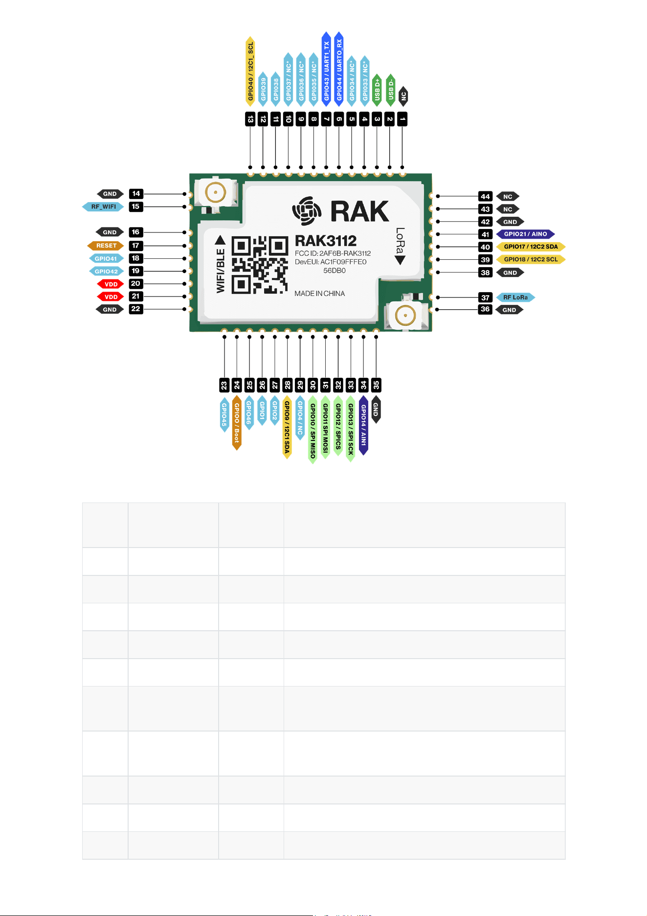
Figure 2: RAK3112 module pinout diagram
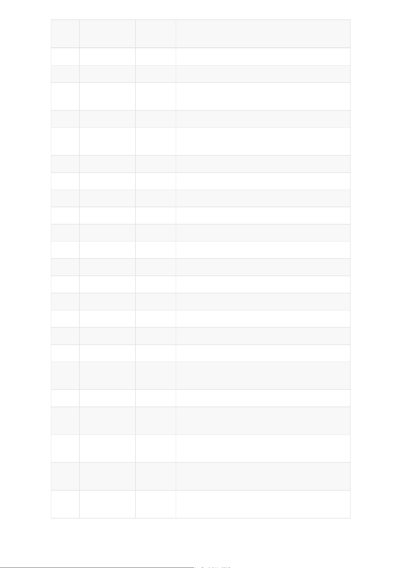
Pin
No.
Name Type Description
1 NC -- Not connected
2 USB_D- USB USB -
3 USB_D+ USB USB +
4 GPIO33 / NC* -- GPIO (not available with 16MB Flash)
5 GPIO34 / NC* -- GPIO (not available with 16MB Flash)
6
GPIO44 /
UART0_RX
I/O
UART
GPIO / UART RX
7
GPIO43 /
UART1_TX
I/O
UART
GPIO / UART TX
8 GPIO35 / NC* -- GPIO (not available with 16MB Flash)
9 GPIO36 / NC* -- GPIO (not available with 16MB Flash)
10 GPIO37 / NC* -- GPIO (not available with 16MB Flash)
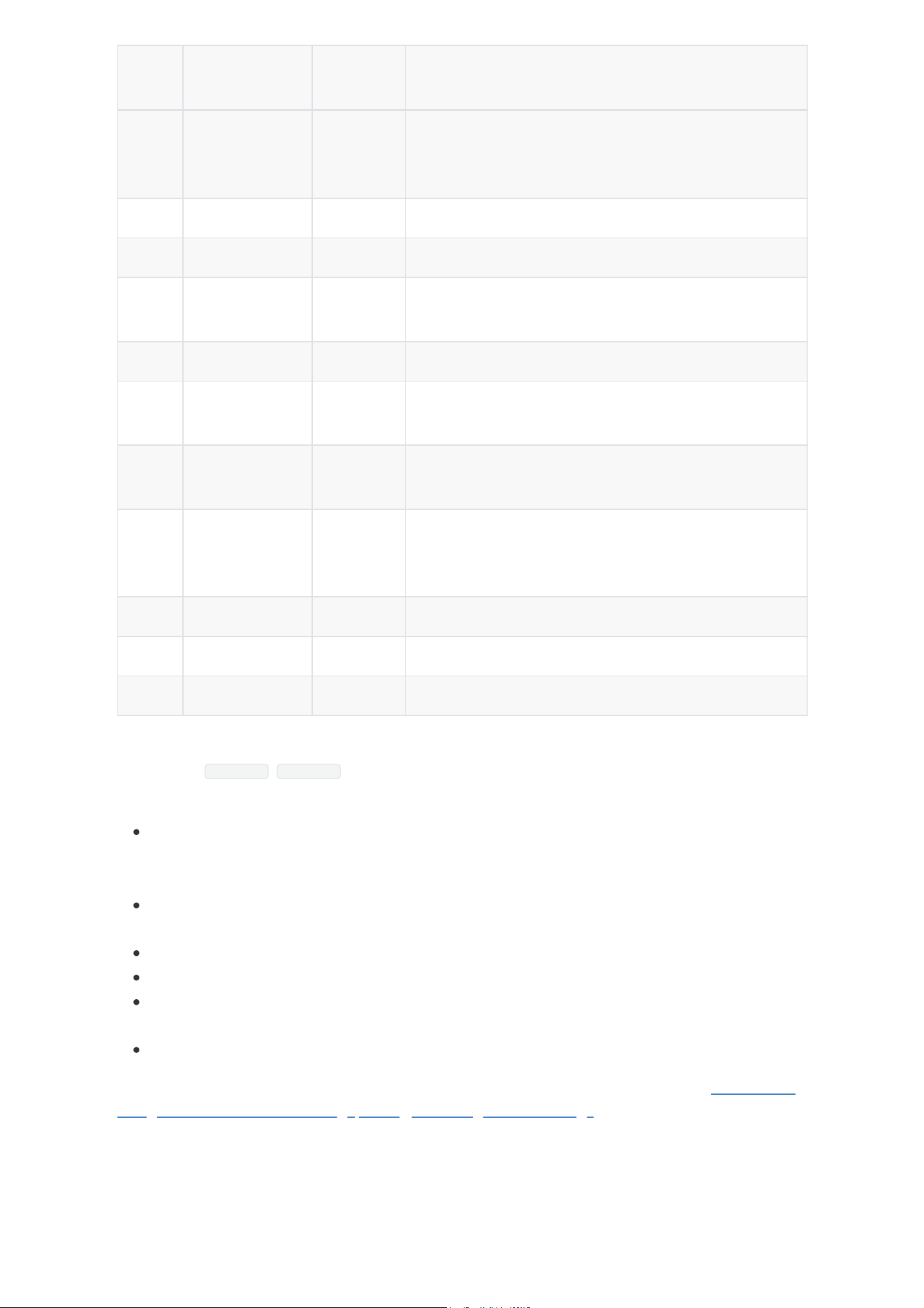
Pin
No.
Name Type Description
11 GPIO38 I/O GPIO
12 GPIO39 I/O GPIO
13
GPIO40 /
I2C1_SCL
I/O I2C GPIO / I2C SCL
14 GND POWER Ground connections
15 RF_WiFi RF
Wi-Fi RF Port (only available on RAK3112 NO-IPEX
connector variant)
16 GND POWER Ground connections
17 RESET Reset ESP32S3 Reset
18 GPIO41 I/O GPIO
19 GPIO42 I/O GPIO
20 VDD POWER VDD - Voltage Supply
21 VDD POWER VDD - Voltage Supply
22 GND POWER Ground connections
23 GPIO45 I/O GPIO
24 GPIO0 / Boot I/O Boot GPIO Bootloader force
25 GPIO46 I/O GPIO
26 GPIO1 I/O GPIO
27 GPIO2 I/O GPIO
28
GPIO9 /
I2C1_SDA
I/O I2C GPIO / I2C SDA
29 GPIO4 / NC I/O GPIO (not available)
30
GPIO10 /
SPI_MISO
I/O SPI GPIO / SPI MISO
31
GPIO11 /
SPI_MOSI
I/O SPI GPIO / SPI MOSI
32
GPIO12 /
SPI_CS
I/O SPI GPIO / SPI CS
33
GPIO13 /
SPI_SCK
I/O SPI GPIO / SPI SCK
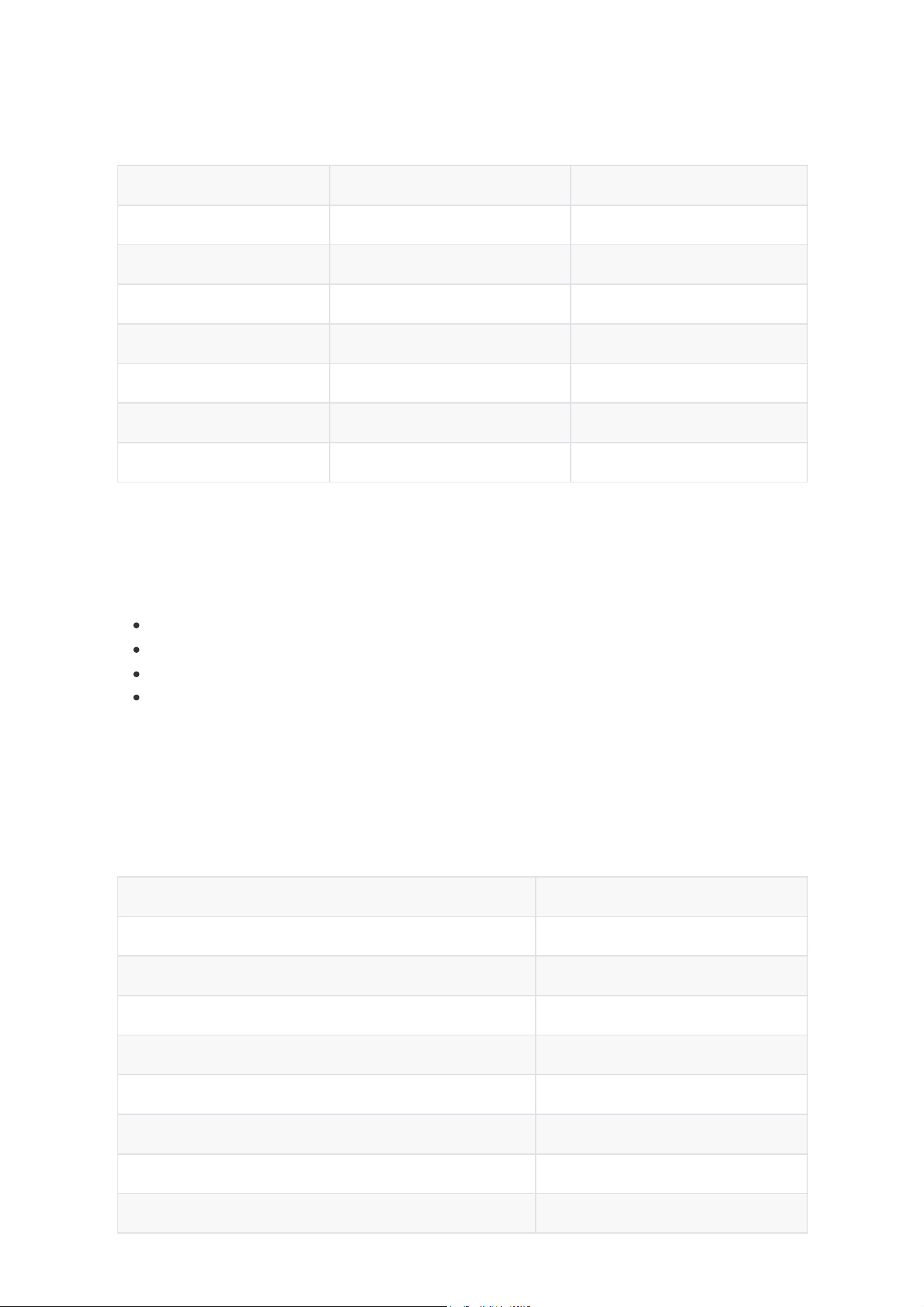
Pin
No.
Name Type Description
34
GPIO14 /
AIN1
I/O
Analog
In
GPIO / Analog In
35 GND POWER Ground connections
36 GND POWER Ground connections
37 RF_LoRa RF
LoRa RF Port (only available on RAK3112 NO-IPEX
connector variant)
38 GND POWER Ground connections
39
GPIO18 /
I2C2_SCL
I/O I2C GPIO / I2C SCL
40
GPIO17 /
I2C2_SDA
I/O I2C GPIO / I2C SDA
41
GPIO21 /
AIN0
I/O
Analog
In
GPIO / Analog In
42 GND I/O Ground connections
43 NC -- Not connected
44 NC -- Not connected
Warning
When using RF_LoRa , RF_WIFI pins for antenna and not the IPEX connector variant, there are
design considerations to make sure optimum RF performance.
RF traces must be away from interference (switching nodes of DC-DC supplies, high-
current/voltage pulses from controllers of inductive loads like motors, signal generators,
etc.).
RF traces must have 50 Ω impedance. It is advisable to use an impedance simulation
software tool to achieve this requirement.
If using an external antenna connector, place it close to the LoRa RF and BLE RF pins.
Ground plane optimization is critical for certain antenna types like monopoles.
The GND trace used for the RF return path must be directly connected to the GND plane and
not treated as a thermal relief.
It is recommended that RF traces be routed in curves, not sharp 90 degree angles.
In addition, with our commitment to making IoT easy, we offer dedicated service for Antenna RF
Design which includes PCB design, tuning, matching and RF testing.
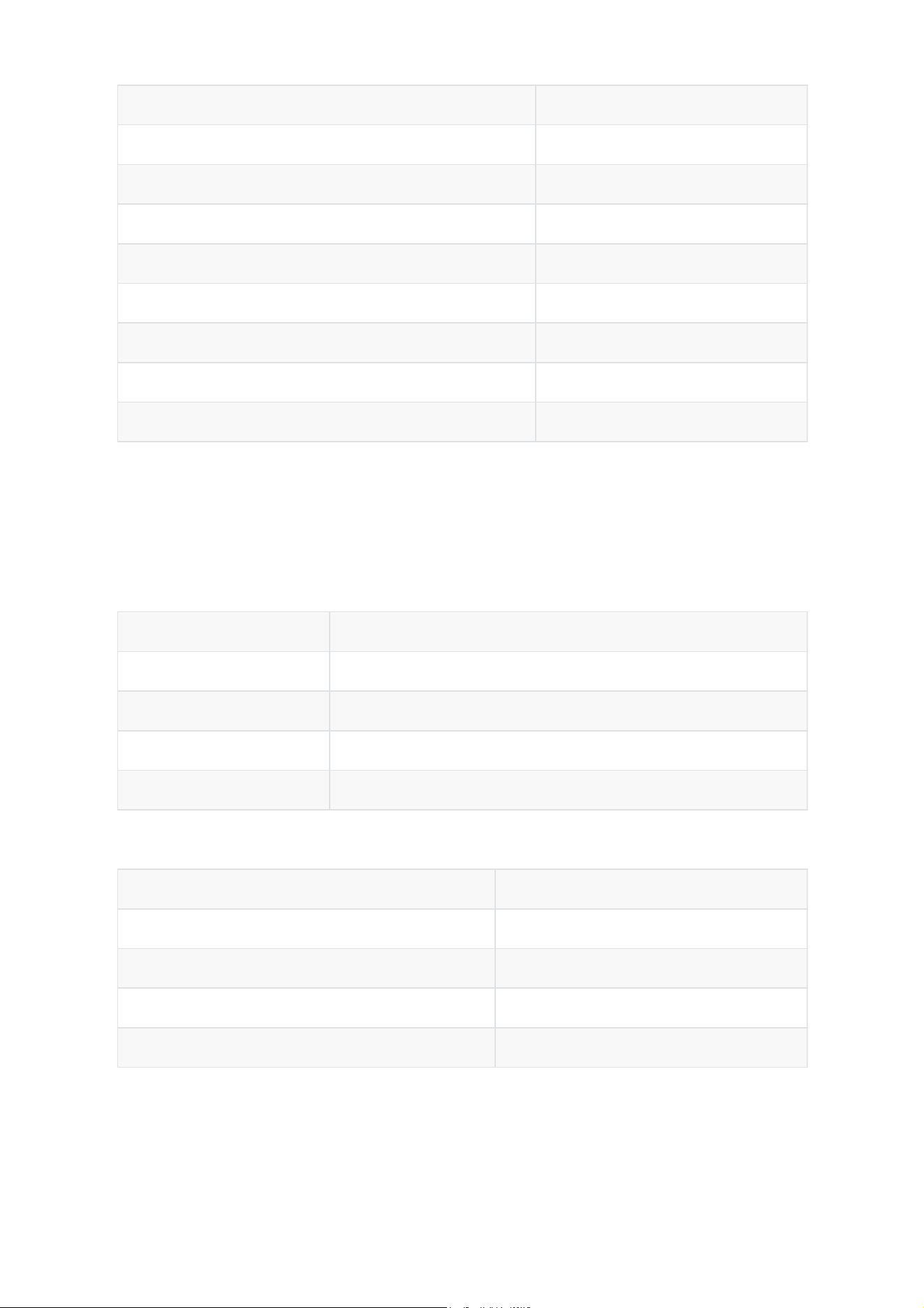
Module Region Frequency
RAK3112 (H) Europe EU868
North America US915
Australia AU915
Korea KR920
Asia AS923-1/2/3/4
India IN865
Russia RU864
Rate Type (dBm)
802.11b, 1 Mbps 21.0
802.11b, 11 Mbps 21.0
802.11g, 6 Mbps 20.5
802.11g, 54 Mbps 19.0
802.11n, HT20, MCS0 19.5
802.11n, HT20, MCS7 19.0
802.11n, HT40, MCS0 19.5
802.11n, HT40, MCS7 18.0
RF Characteristics
LoRa Transceiver
The RAK3112 module supports many LoRaWAN bands as shown in the table below.
TX Power
Transmitter output power, programmable up to +22 dBm.
RX Sensitivity
-124 dBm for LoRa(BW = 125 kHz, SF = 7)
-121 dBm for LoRa (BW = 250 kHz, SF = 7)
-137 dBm for LoRa (BW = 125 kHz, SF = 12)
-134 dBm for LoRa(BW = 250 kHz, SF = 12)
Wi-Fi
Operating Frequencies
2400-2483.5 MHz
TX Power
Rate Type (dBm)
802.11b, 1 Mbps –98.4
802.11b, 11 Mbps -88.6
802.11g, 6 Mbps –93.2
802.11g, 54 Mbps –76.5
802.11n, HT20, MCS0 –92.6
802.11n, HT20, MCS7 –74.2
802.11n, HT40, MCS0 –90.0
802.11n, HT40, MCS7 –71.4
Rate Type (dBm)
BLE @1 Mbps Programmable from -24 dBm to 20 dBm
BLE @2 Mbps Programmable from -24 dBm to 20 dBm
BLE @125 Kbps Programmable from -24 dBm to 20 dBm
BLE @500 Kbps Programmable from -24 dBm to 20 dBm
Rate Type (dBm)
BLE @1 Mbps –97.5
BLE @2 Mbps –93.5
BLE @125 Kbps –104.5
BLE @500 Kbps –101
RX Sensitivity
Bluetooth
Operating Frequencies
2402 ~ 2480 MHz
TX Power
RX Sensitivity
Electrical Characteristics
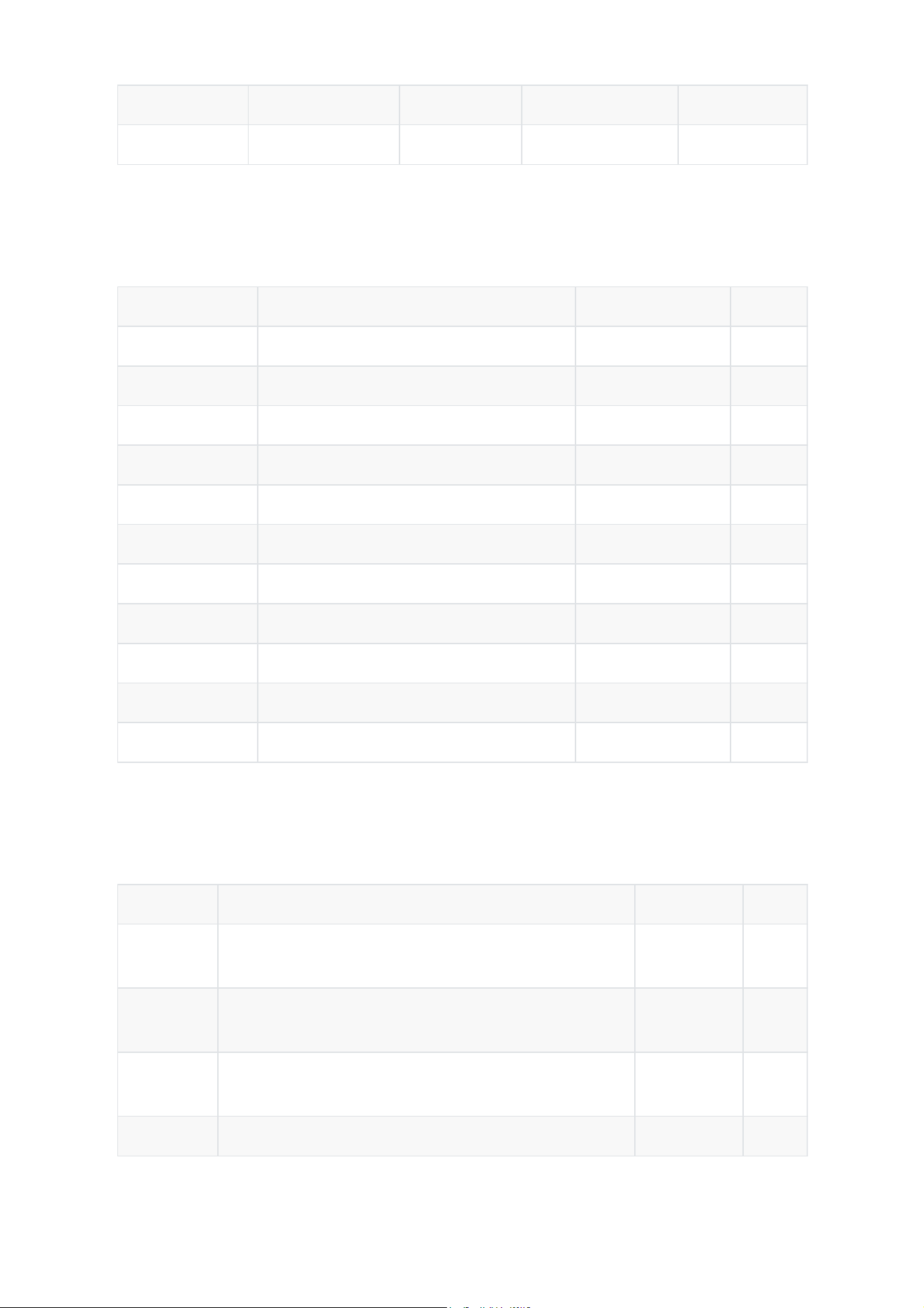
Feature Minimum Typical Maximum Unit
VDD 3.0 3.3 3.6 Volts (V)
Work Mode Condition Peak current Unit
Wi-Fi TX 802.11b, 1 Mbps, @21 dBm 340 mA
802.11g, 54 Mbps, @19 dBm 291 mA
802.11n, HT20, MCS7, @18.5 dBm 283 mA
802.11n, HT40, MCS7, @18 dBm 286 mA
Wi-Fi RX 802.11b/g/n, HT20 88 mA
802.11n, HT40 91 mA
Lora TX +22 dBm@ 868 to 915Mhz 140 mA
+20 dBm@ 868 to 915 Mhz 127.5 mA
+17 dBm@ 868 to 915 Mhz 118 mA
+14 dBm@ 868 to 915 Mhz 112 mA
Lora RX LoRa 125 kHz 25.46 mA
Feature Condition Maximum Unit
Light-
sleep
VDD_SPI and Wi-Fi are powered down, and all GPIOs
are high-impedance.
241 uA
Deep-
sleep 1
RTC memory and RTC peripherals are powered up. 9 uA
Deep-
sleep 2
RTC memory is powered up. RTC peripherals are
powered down.
8 uA
Power off CHIP_PU is set to low level. The chip is shut down. 2 uA
Operating Voltage
Operating Current
The current consumption measurements are taken with a 3.3 V supply at 25° C of ambient
temperature.
Sleep Current
The current consumption measurements are taken with a 3.3 V supply at 25° C of ambient
temperature.
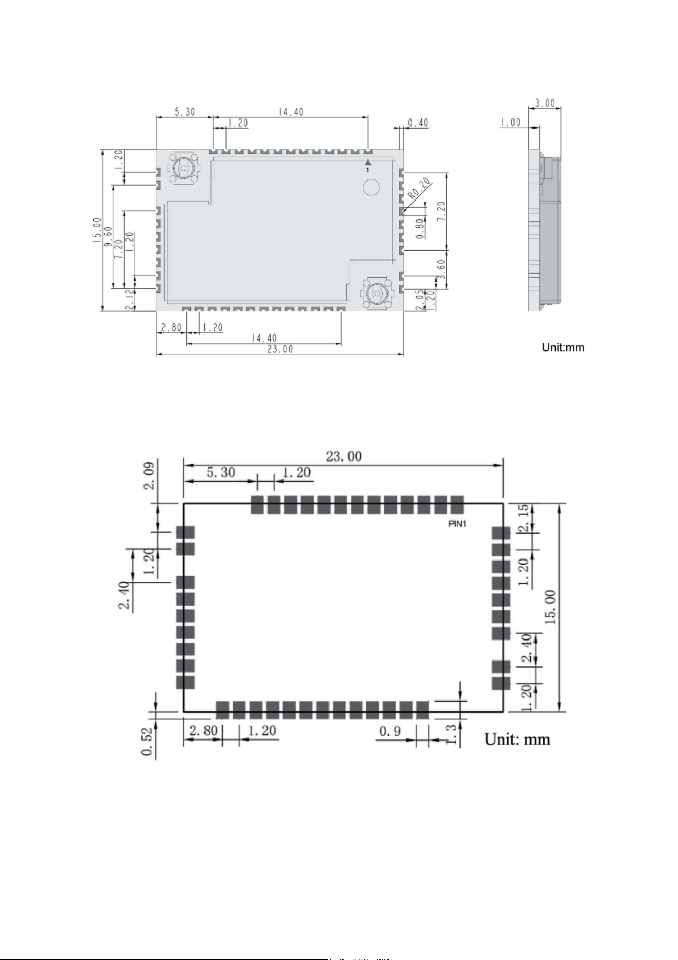
Feature Minimum Typical Maximum Unit
Operating Temperature -40 25 65 ° C
Feature Minimum Typical Maximum Unit
Storage Temperature -40 - 65 ° C
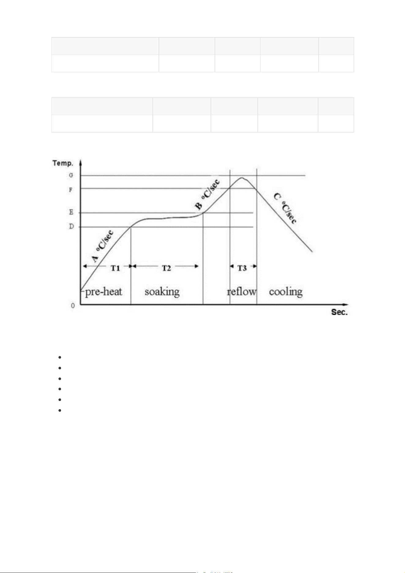
Figure 5:Reflow Profile for RAK3112
Operating Temperature
Storage Temperature
Recommended Reflow Profile
Standard conditions for reflow soldering:
Pre-heating Ramp (A) (Initial temperature: 150° C): 1 ~ 2.5° C/sec
Soaking Time (T2) (150 ~ 180° C): 60 ~ 100 sec
Peak Temperature (G): 230 ~ 250° C
Reflow Time (T3) (> 220° C): 30 ~ 60 sec
Ramp-up Rate (B): 0 ~ 2.5° C/sec
Ramp-down Rate (C): 1 ~ 3° C/sec
Schematic Diagram (Minimal)

Hereby, Shenzhen RAKwireless Technology Co.,Ltd. declares that the radio equipment
type RAK3112/RAK3312 is in compliance with Directive 2014/53/EU.
The full text of the EU declaration of conformity is available at the following internet
address: XXXX
Federal Communication Commission Interference Statement
This equipment has been tested and found to comply with the limits for a Class B digital
device, pursuant to Part 15 of the FCC Rules. These limits are designed to provide
reasonable protection against harmful interference in a residential installation. This
equipment generates, uses and can radiate radio frequency energy and, if not installed
and used in accordance with the instructions, may cause harmful interference to radio
communications. However, there is no guarantee that interference will not occur in a
particular installation. If this equipment does cause harmful interference to radio or
television reception, which can be determined by turning the equipment off and on, the
user is encouraged to try to correct the interference by one of the following measures:
- Reorient or relocate the receiving antenna.
- Increase the separation between the equipment and receiver.
- Connect the equipment into an outlet on a circuit different from that to which the
receiver is connected.
- Consult the dealer or an experienced radio/TV technician for help.
FCC Caution: Any changes or modifications not expressly approved by the party
responsible for compliance could void the user's authority to operate this equipment.

This device complies with Part 15 of the FCC Rules. Operation is subject to the following
two conditions:
(1) This device may not cause harmful interference, and
(2) This device must accept any interference received, including interference that may
cause undesired operation.
FCC Radiation Exposure Statement:
This equipment complies with FCC radiation exposure limits set forth for an
uncontrolled environment. This equipment should be installed and operated with
minimum distance 20cm between the radiator & your body. This transmitter must not
be co-located or operating in conjunction with any other antenna or transmitter.
This device is intended only for OEM integrators under the following conditions:
1. The antenna must be installed such that 20 cm is maintained between the antenna
and users, and
2. The transmitter module may not be co-located with any other transmitter or antenna,
IMPORTANT NOTE:
In the event that these conditions cannot be met (for example certain laptop
configurations or co-location with another transmitter), then the FCC authorization is
no longer considered valid and the FCC ID cannot be used on the final product. In these
circumstances, the OEM integrator will be responsible for re-evaluating the end product
(including the transmitter) and obtaining a separate FCC authorization.

End Product Labelling
This transmitter module is authorized only for use in device where the antenna may be
installed such that 20 cm may be maintained between the antenna and users.
The final end product must be labelled in a visible area with the following:
“Contains FCC ID: 2AF6B-3112”.
Manual Information to the End User
The OEM integrator has to be aware not to provide information to the end user
regarding how to install or remove this RF module in the user’s manual of the end
product which integrates this module.
Canada Statement
This device complies with Industry Canada licence-exempt RSS standard(s). Operation
is subject to the following two conditions: (1) this device may not cause interference,
and (2) this device must accept any interference, including interference that may cause
undesired operation of the device.
Le présent appareil est conforme aux CNR d'Industrie Canada applicables aux appareils
radio exempts de licence. L'exploitation est autorisée aux deux conditions suivantes : (1)
l'appareil ne doit pas produire de brouillage, et (2) l'utilisateur de l'appareil doit accepter
tout brouillage radio é lectrique subi, m ê me si le brouillage est susceptible d'en

compromettre le fonctionnement.
The device meets the exemption from the routine evaluation limits of RSS 102 and
compliance with RSS-102 RF exposure, users can obtain Canadian information on RF
exposure and compliance.
Le dispositif rencontre l'exemption des limites courantes d'évaluation dans de RSS 102
et la conformité à l'exposition de RSS-102 rf, utilisateurs peut obtenir l'information
canadienne sur l'exposition et la conformité de rf.
This transmitter must not be co-located or operating in conjunction with any other
antenna or transmitter. This equipment should be installed and operated with a
minimum distance of 20 centimeters between the radiator and your body.
Cet émetteur ne doit pas être Co-placé ou ne fonctionnant en même temps qu'aucune
autre antenne ou émetteur. Cet équipement devrait être installé et actionné avec une
distance minimum de 20 centimètres entre le radiateur et votre corps.
The final end product must be labeled in a visible area with the following:
The Industry Canada certification label of a module shall be clearly visible at all times
when installed in the host device, otherwise the host device must be labelled to display
the Industry Canada certification number of the module, preceded by the words
“Contains transmitter module”, or the word “Contains”, or similar wording expressing

the same meaning, as follows:
Contains transmitter module IC: 25908-3112
where 25908-3112 is the module’s certification number.
This device has been designed to operate with the antenna listed below, and having a
peak gain of 3.12dBi @ 2.4GHz, 0.8dbi @lora PCB antenna, 2.37dBi @lora dipole
antenna. Antennas not of the same type and having a higher gain specified above are
strictly prohibited for use with this device. The required antenna impedance is 50 ohms.
Wifi antenna:
Model:S2B1BH2A1B01000
Tpye:PCB Antenna / 3.12dBi
Vendor: Unictron Technologies Corporation
Address: 09, 6F, Building B, New Compark, Pingshan 1st Road, Nanshan, Shenzhen,
Lora PCB antenna:
Model:S 2B 1O D 3A1L02000
Type: PCB Antenna/ 0.8dbi
Vendor: Unictron Technologies Corporation
Address: 09, 6F, Building B, New Compark, Pingshan 1st Road, Nanshan, Shenzhen,
Guangdong, China
LORA DIPOLE ANTENNA:
MODEL: 81800V294/ 81800V296
TYPE: DIPOLE ANTENNA/2.37dbi

Vendor:
Electric Connector Technology Address : Electric Connector Technology Park, No. 171
Changfeng Road, Yutang Street, Guangming District, Shenzhen City, Guangdong
Province, China