CIRCUIT FINDER
Breaker ID Pro 300
Circuit Breaker Finder Kit
EN
TROUBLESHOOTING & CONSTRUCTION TIPS
SITUATION LIKELY CAUSE SOLUTION
No indication:
no green LED
and buzzer.
The breaker for that circuit is
not in the box being scanned.
Find and scan the box that supplies that circuit.
The breaker is off. Look for the breaker that is off and turn it on.
Multiple indications
on second scan.
First scan was performed
too quickly.
Scan again, moving the Receiver slowly.
Keep the nose of the Receiver close to
the breaker, and maintain proper orientation.
Receiver indicates
breaker above the
correct one.
Receiver is held at an incorrect
angle, with only the tip of the
Receiver contacting the breaker.
Hold the Receiver at an angle so the entire
Contact Area of the Receiver touches each
circuit breaker as shown in Figures B, C, and D.
Receiver does
not operate.
Low battery.
Install new 9V alkaline battery with an
extended expiration date at least 3 years
beyond the current date.
BEFORE YOU BEGIN
ZIRCON
®
CIRCUIT BREAKER FINDERS WORK BY SENSING AN ELECTRONIC SIGNAL FROM
THE TRANSMITTER.
- Always use a new 9V alkaline battery with an extended expiration date at least 3 years beyond
the current date. Match battery direction to image inside of battery cavity.
- Readings should always be consistent and repeatable.
- Zircon circuit breaker finders should be used in a dry environment.
- Compatible with aluminum and copper circuit wiring.
- Clean transmitter with dry cloth only. Do not expose product to liquids.
- If the device is used in a manner not specified here, then the protection provided by the device
may be impaired.
- 80–300 V AC, 50–60 Hz, 4 W maximum.
- Maximum altitude: 2,188 yd (2,000 m).
- Maximum operating temperature: 104°F (40°C).
- Pollution Degree 2 or less.
- Maximum humidity: 80%.
- No part of this device may be replaced or repaired by anyone except the manufacturer.
- Device must be used on a live circuit.
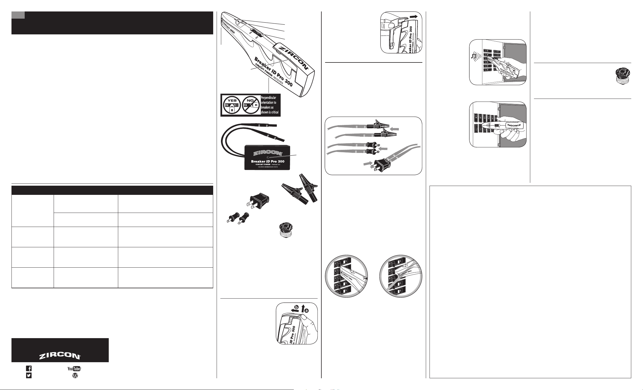
Receiver
Green LED
Red LED
Orientation
Label On Bottom
of Receiver
ON / OFF Switch
Transmitter
Red LED
Battery Cover /
Belt Clip
3. Slide the cover back
on the Receiver until it
snaps in place.
LOCATE A CIRCUIT
In a three-phase application, the Transmitter
may be connected between any power line
and neutral, or from line to line not to exceed
300 V AC, in both wye and delta type power
configurations.
1. Attach the appropriate Accessory(ies) to the
Transmitter. (Figure A)
2. Connect the Transmitter to the circuit to be
identified. The Red LED will blink approximately
five seconds then glow solid to indicate the
Transmitter is functioning and the circuit is live.
3. At the circuit panel, turn the Receiver to ON.
4. Holding the Receiver at an angle that gives
maximum contact between the Contact Area and
the breaker, slowly scan all breakers. (Figure B)
The Contact Area must touch each breaker
during the scan.
The first scan calibrates the tool. During first
scan, the Receiver may indicate more than one
breaker. This is normal. If there is more than one
panel, perform this step on each panel without
turning the Receiver off.
5. Perform a second pass over the breakers to
identify the breaker that corresponds with the
outlet where the Transmitter is plugged in.
When the green LED glows and the buzzer
sounds, the Receiver is directly over the breaker
for the outlet where Transmitter is plugged in.
Note:
Some circuit
boxes are
mounted
with breakers
oriented
vertically.
See Figures
C and D for
proper Receiver
orientation for
horizontally
or vertically
oriented
breakers.
Contact
Area
6. Once the correct breaker is identified, turn it
off and label the breaker for future reference.
7. With the Transmitter still plugged in,
verify that the Red LED on the Transmitter is off,
indicating a dead circuit, before beginning work.
TRACE THE CIRCUIT FOR
A LIGHT FIXTURE
Screw the Light Socket Adapter into
the socket where a bulb would
normally go, then plug the Transmitter
into the Adapter.
STORE THE TOOL
Before storing, use a dry cloth to clean the parts.
Do not expose the tool to liquids.
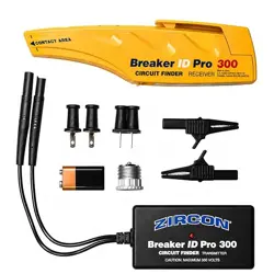
Accessories
Alligator Clips
(connect to bare or
exposed wire)
120 V AC Plug
Light Socket
Adapter
Blades (use with angled
plugs such as 220V outlets)
Not Shown: Carrying/Storage Case
CAUTION: In no event may the Breaker ID
Pro Transmitter be used where the voltage
across the Transmitter exceeds 300 V AC,
as this will cause failure of the device
with consequent damage beyond repair.
INSTALL BATTERY
1. Remove the Receiver
battery cover by lifting (a)
and sliding (b) as shown.
NOTE: If the clip is too
tight to move easily,
use a flat-head
screwdriver to gently
pry open.
2. Slide a new 9V alkaline battery into
the compartment, terminals first, matching
+
and
− on the battery with markings in
the compartment.
Figure A
LIMITED 1 YEAR WARRANTY
Zircon Corporation (“Zircon”) warrants
to the product owner that this product
will be free from defects in materials and
workmanship for one year from the original
date of purchase. Any defective product
returned to Zircon within the warranty
period to the address below, freight
prepaid, along with proof of purchase, will
be repaired or replaced, at Zircon’s option.
Repair or replacement may be made with a
new or refurbished product or components,
at Zircon’s sole discretion. If the returned
product is no longer available, Zircon may
replace the product with a similar product
of similar function. This warranty is limited
to the electronic circuitry of the product
and original case of the product, and
specifically excludes any damage caused by
abuse, modification, handling contrary to
these instructions, other unreasonable use,
or neglect. This is your sole and exclusive
remedy for breach of this Limited Warranty.
This Limited Warranty is in lieu of all other
warranties, express or implied, and no
other representations or claims of a
similar nature will bind or obligate Zircon.
Any implied warranties applicable to this
product that cannot be disclaimed are
limited to the one year period following
its purchase. This Limited Warranty does
not cover consumable parts, including
batteries, or software, even if packaged
with the product.
IN NO EVENT WILL ZIRCON BE LIABLE
FOR ANY SPECIAL, INCIDENTAL OR
CONSEQUENTIAL DAMAGES RESULTING
FROM POSSESSION, USE OR MALFUNCTION
OF THIS PRODUCT.
Some states do not allow limitations on
certain implied warranties and/or the
limitation on incidental or consequential
damages, so the above limitations
and exclusions may not apply to you.
This warranty gives you specific legal
rights, and you may also have other rights
which vary from state to state.
Return products for warranty service,
freight prepaid with proof of purchase
(a dated sales receipt) to:
Zircon Corporation
Attn: Returns Department
1580 Dell Avenue
Campbell, CA 95008-6992 USA
Be sure to include your name and return
address. Allow 4–6 weeks for delivery.
Customer Service: 1-800-245-9265 or
1-408-963-4550
Monday–Friday, 8:00 a.m.–5:00 p.m. PT
[email protected] • www.zircon.com
©2018 Zircon Corporation • P/N 70114
Rev B 10/18
Zircon is a registered trademark of
Zircon Corporation.
Figure B
Correct Incorrect
Figure C
Horizontal Breakers
Figure D
Vertical Breakers
Visit www.zircon.com for the
most current instructions.
FCC Part 15 Class B Registration Warning: This device
complies with Part 15 of FCC Rules. Operation is
subject to the following two conditions: (1) this device
may not cause harmful interference, and (2) this device
must accept any interference received, including
interference that may cause undesired operation.
ZirconCorporation ZirconTV
ZirconTools
|
ZirconToolPro
ZirconTools
CIRCUIT FINDER
Breaker ID Pro 300
Localizador de Interruptores
ES
ANTES DE EMPEZAR
LOS LOCALIZADORES DE INTERRUPTORES DE CIRCUITO DE ZIRCON
®
FUNCIONAN MEDIANTE LA
SEÑAL ELECTRÓNICA DEL TRANSMISOR.
- Siempre use una nueva batería alcalina de 9V con una fecha de vencimiento extendida por lo
menos 3 años más allá de la fecha actual. Haga coincidir la dirección de la batería con la imagen
dentro de la cavidad de la batería.
- Las lecturas siempre deben ser consistentes y repetibles.
- Los localizadores de interruptores de circuito de Zircon deben usarse en un ambiente seco.
- Compatible con cableado de circuito de aluminio y cobre.
- Limpie el transmisor solamente con un trapo seco. No exponga el producto a líquidos.
- Si el dispositivo se utiliza de una manera no especificada aquí, entonces la protección
proporcionada por el dispositivo puede verse afectada.
- 80–300 V AC*, 50–60 Hz, 4 W máximo.
- Altitud máxima: 2,188 yd (2,000 m).
- Temperatura operativa máxima: 104°F (40°C).
- Grado de contaminación 2 o menor.
- Humedad máxima: 80%.
- Ninguna parte de este dispositivo puede ser reemplazada o reparada por nadie más que
el fabricante.
- El dispositivo debe ser utilizado en un circuito con corriente.
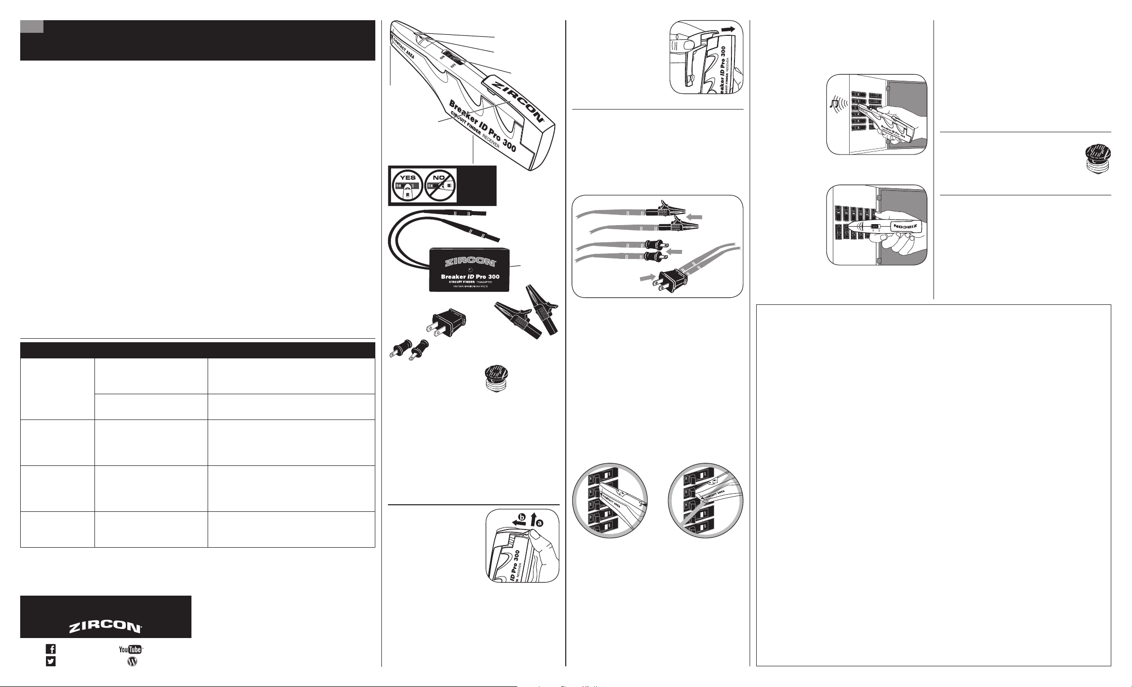
Etiqueta
de Orientación
en el Lado Inferior
del Receptor
Transmisor
LED Rojo
3. Deslice la tapa hacia
atrás en el receptor hasta
que se encaje en su lugar.
LOCALIZAR UN CIRCUITO
En una aplicación trifásica, el transmisor se
puede conectar entre cualquier línea de
alimentación y neutral, o de línea a línea sin
sobrepasar 300 V AC*, en configuraciones de
energía de tipo de estrella y triángulo.
1. Conecte el accesorio apropiado al
transmisor. (Figura A)
2. Conecte el transmisor al circuito que
se identificará. El LED rojo parpadeará
aproximadamente cinco segundos y luego se
iluminará de manera continua para indicar que
el transmisor está funcionando y que el circuito
está activo.
3. Encienda el receptor cerca del panel
de circuitos.
4. Sosteniendo el receptor en un ángulo que
proporcione el máximo contacto entre el área
de contacto y el interruptor, escanee lentamente
todos los interruptores. (Figura B)
El Área de Contacto debe tocar cada interruptor
durante el escaneo.
El primer escaneo calibra el receptor. Durante el
primer escaneo, el receptor puede indicar más
de un interruptor. Esto es normal. Si hay más de
un panel, realice este paso en cada panel sin
apagar el Receptor.
5. Realice una segunda pasada sobre los
interruptores para identificar el interruptor que
corresponde con la salida donde está enchufado
el transmisor.
Cuando el LED verde se ilumina y el tono suena,
el receptor está directamente sobre el interruptor
de la toma de corriente donde el transmisor está
enchufado.
Nota: Algunas
cajas de
circuitos están
montadas con
interruptores
orientados
verticalmente.
Consulte las
Figuras C y D
para conocer
la orientación
correcta del
receptor para
interruptores
orientados
horizontal o
verticalmente.
6. Una vez que se identifique el
interruptor correcto, apáguelo y etiquételo
para futuras referencias.
7. Con el transmisor todavía enchufado,
verifique que el LED rojo en el transmisor esté
apagado, indicando que el circuito no está
activo, antes de comenzar a trabajar.
RASTREAR EL CIRCUITO PARA
UNA LUZ DE FIJACIÓN
Atornille el Adaptador de Enchufe de
Luz en el enchufe donde normalmente
iría una bombilla, luego enchufe el
transmisor en el Adaptador.
ALMACENAR EL DISPOSITIVO
Antes de almacenar, use un paño seco para
limpiar las piezas. No exponga el dispositivo
a líquidos.
*AC: Se refiere a corriente alterna (CA).
Accesorios
Clips (se conectan al cable
desnudo o expuesto)
Enchufe de
120 V AC*
Adaptador de
Enchufe de luz
Cuchillas (se usan con
enchufes en ángulo tales
como salidas de 220 V)
No mostrada: Estuche de transporte
/ almacenamiento
PRECAUCIÓN: En ningún caso se puede
utilizar el transmisor Breaker ID Pro
cuando la tensión en el transmisor exceda
los 300 V AC*, ya que esto provocará la
falla del dispositivo con el consiguiente
daño sin posibilidad de reparación.
INSTALAR LA BATERÍA
1. Quite la tapa de
la batería del receptor
levantando (a) y deslizando
(b) como se muestra.
NOTA: Si la tapa está
demasiado apretada para
moverse con facilidad,
use un destornillador de cabeza
plana para abrirla suavemente.
2. Coloque una nueva batería alcalina de
9V en el compartimento, terminales primero,
haciendo coincidir los polos positivo (+)
y negativo (-) de la batería con las marcas
en el compartimento.
Figura C
Interruptores Horizontales
Figura D
Interruptores Verticales
GARANTIA LIMITADA DE 1 AÑO
El Corporativo Zircon (“Zircon”) garantiza al
cliente que este producto se encuentra libre
de defectos en sus materiales y mano de
obra por un periodo de un año a partir de
la fecha de su compra. Cualquier producto
defectuoso devuelto a Zircon dentro del
periodo de garantía a la dirección indicada
abajo, con flete prepagado y comprobante
de la compra, será reparado o reemplazado
a discreción de Zircon. La reparación o
reemplazo puede hacerse con un producto
y componentes nuevos o restaurados a
discreción de Zircon. Si el producto devuelto
ya no está disponible, Zircon puede sustituir
el producto por un producto similar en base
a su funcionamiento. Esta garantía se limita
a los circuitos electrónicos del producto
y a su carcasa original, y específicamente
excluye cualquier daño causado por abuso,
modificación, manejo contrario de uso de
estas instrucciones, otro uso no razonable
o negligencia. Este es su único y exclusivo
recurso para el incumplimiento de esta
Garantía Limitada.
Esta garantía limitada es una parte de otras
garantías, expresas o implícitas y Zircon no
será responsable por ninguna otra afirmación
o reclamo de naturaleza similar. Toda garantía
implícita que se aplique a este producto está
limitada a un periodo de un año a partir de la
fecha de su compra. Esta garantía limitada no
cubre las piezas consumibles, incluidas como
las baterías o el software, incluso si están
empaquetadas con el producto.
EN NINGÚN CASO ZIRCON SERÁ
RESPONSABLE POR CUALQUIER DAÑO
ESPECIAL, INCIDENTAL O COMO
CONSECUENCIA DE LA POSESIÓN, USO O EL
MAL FUNCIONAMIENTO DE ESTE PRODUCTO.
Algunos estados no permiten limitaciones en
cuanto al periodo de duración de una garantía
implícita y/o a la exclusión o a la limitación
de daños secundarios o consecuentes, de
modo que las limitaciones y/o exclusiones
mencionadas anteriormente pueden no ser
aplicables en su caso. Esta garantía le otorga
derechos legales específicos, y Usted también
podría tener otros derechos que pueden
variar de estado a estado.
Envíe el producto con flete prepagado y el
comprobante con la fecha de compra (recibo
de ventas con fecha) a:
Zircon Corporation, Attn: Returns Department
1580 Dell Avenue
Campbell, CA 95008-6992 USA
Asegúrese de incluir su nombre y dirección
para la devolución. Permita de 4 a 6 semanas
para la entrega.
Atención al Cliente, 1-800-245-9265 ó
1-408-963-4550
Lunes a Viernes, 8:00 a.m. a 5:00 p.m.
Hora Estándar del Pacífico
[email protected] • www.zircon.com
©2018 Zircon Corporation • P/N 70114
Rev B 10/18
Zircon es una marca registrada de
Zircon Corporation.
CONSEJOS ÚTILES & CONSEJOS PARA CONSTRUCCIÓN
SITUACIÓN CAUSAS PROBABLES SOLUCIONES
Sin indicación: es
decir, no LED verde
y tono audio.
El interruptor para ese
circuito no está en la caja que
se está escaneando.
Encuentre y escanee la caja que suministra
ese circuito.
El interruptor está apagado.
Busque el interruptor que está apagado
y enciéndalo.
Múltiples
indicaciones
durante el
segundo escaneo.
El primer escaneo se realizó
demasiado rápidamente.
Escanee de nuevo, moviendo el receptor
lentamente. Mantenga la punta del receptor
cerca del interruptor y mantenga una
orientación adecuada.
Receptor indica
que el interruptor
por encima es
el correcto.
El receptor se mantiene en un
ángulo incorrecto, con sólo la
punta del receptor en contacto
con el interruptor.
Sostenga el receptor en un ángulo para que
toda el área de contacto del receptor toque
cada interruptor como se muestra en las Figuras
B, C, y D.
El receptor
no funciona.
Batería baja.
Instale una nueva batería alcalina de 9V con
una fecha de vencimiento extendida por lo
menos 3 años más allá de la fecha actual.
Receptor
LED Verde
LED Rojo
Interruptor
Encendido /
Apagado
Tapa de la
Batería / Clip
de Cinturón
Área de
Contacto
Figura B
Correcto Incorrecto
Figura A
Advertencia de Registro de la Parte 15 del FCC
Clase B: Este aparato cumple con las reglas
Parte 15 de la FCC. Su operación está sujeta a
las siguientes dos condiciones: (1) este aparato no
puede causar interferencia dañina, y (2) este aparato
debe aceptar cualquier interferencia recibida,
incluyendo la interferencia que pueda causar la
operación no deseada.
ZirconCorporation ZirconTV
ZirconTools
|
ZirconToolPro
ZirconTools
Orientar
perpendicularmente
la unidad con
respecto del
interruptor,
es crítico.
Visite www.zircon.com para las
instrucciones más actualizadas.