

Operator’s Manual
READ AND UNDERSTAND THE ENTIRE MANUAL BEFORE OPERATING MACHINE
MINI SKID
STEER
LOADER


1
TABLE OF CONTENTS
TABLE OF CONTENTS
12
13
TROUBLE SHOOTING
53
PARTS DIAGRAM
57
PARTS LIST
58
PREPARE
19
CONTROLS
23
CONTROL MONITOR
32
TRANSPORT
36
COMPLETE THE JOB
SAFETY LABELS
8
IMPORTANT SAFETY INFORMATION
2
5
SPECIFICATIONS 1
MAINTENANCE INTERVAL CHART
52
MAINTENANCE
37
40
SAFETY PRACTICES
BELT, FAN
41
COOLANT
42
ENGINE COMPARTMENT
42
FILTER, AIR
43
FILTER, FUEL
43
FILTER, HYDRAULIC FLUID
44
FLUID, HYDRAULIC
45
FUEL HOSE
45
FUSE BOX
46
HYDRAULIC HOSES
46
IDLER ROLLER BEARINGS
47
INTAKE AIR LINE
48
LUG NUTS
48
OIL, ENGINE
49
PARKING BRAKE
50
RADIATOR/HYDRAULIC FLUID COOLER
51
TRACK TENSION
61
PARTS DIAGRAM (ENGINE EXPLOSIVE VIEW)
62
PARTS LIST (ENGINE EXPLOSIVE VIEW)
63
PARTS DIAGRAM (HOSE EXPLOSION DIAGRAM)
64
PARTS LIST (HOSE EXPLOSION DIAGRAM)
65
PARTS DIAGRAM (LIFTING ARM ASSEMBLY)
66
PARTS LIST (LIFTING ARM ASSEMBLY)
67
PARTS DIAGRAM (LEFT TRACK ASSEMBLY)
68
PARTS LIST (LEFT TRACK ASSEMBLY)
69
PARTS DIAGRAM (LEFT TRACK ASSEMBLY)
70
PARTS LIST (LEFT TRACK ASSEMBLY)
72
PARTS DIAGRAM (MOUNTING PLATE ASSEMBLY)
73
PARTS LIST (MOUNTING PLATE ASSEMBLY)
74
PARTS DIAGRAM (HEAT DISSIPATION ASSEMBLY)
75
PARTS LIST (HEAT DISSIPATION ASSEMBLY)
8
SAFETY AND INSTRUCTIONAL LABELS
LOCATE UTILITIES
13
CLASSIFY JOBSITE
13
APPLY PRECAUTIONS
17
HYDRAULIC CONNECTION
18
NOISE EMISSION
23
CONTROL MONITOR STARTUP
25
LOCATE UTILITIES
27
DATA ACQUISITION DISPLAY
29
DRIVE

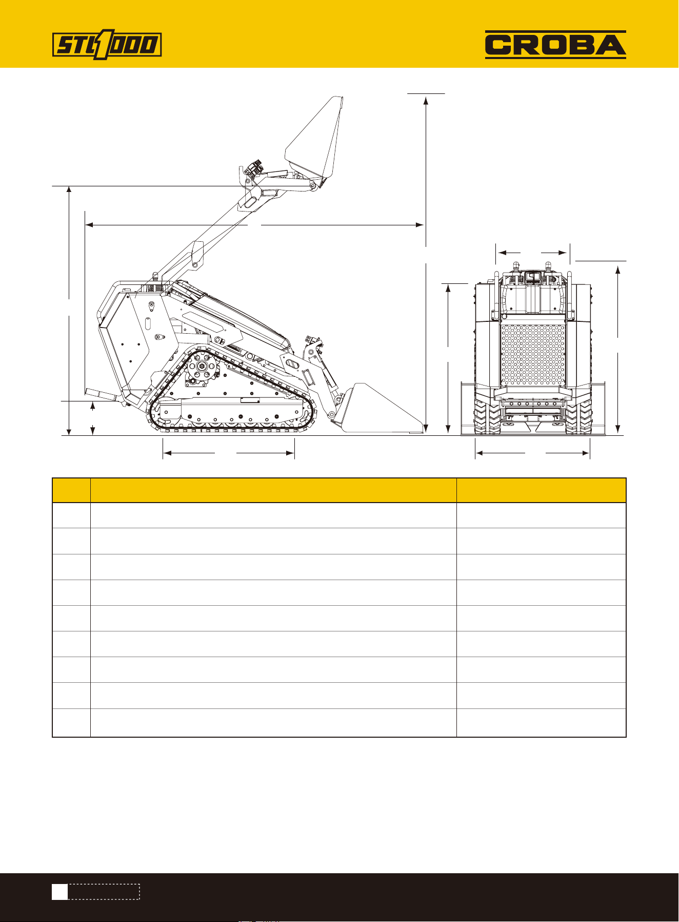
DIMENSIONS
SPECIFICATIONS
2
SPECIFICATIONS
Model STL1000
Engine Model
Type
Total Displacement
Number of cylinder
Brake Horse Power-Net intermittent without fan ISO 14396
Rated Speed
Max. Torque
Low Idling Speed
Overall Length (With 4-In-1 Bucket Parallel To Ground)
Overall Length (w/o 4-In-1 Bucket)
Overall Height
Overall Width With 4-In-1 Bucket
Overall Width w/o 4-In-1 Bucket Bucket
Weight With 4-In-1 Bucket (w/o Operator) Ibs
Weight w/o 4-In-1 Bucket
Rated Operating Capacity (35%)
Tipping Load
Wheelbase
Hinge Pin Height At Max. Lift
Reach At Max. Lift And 45° Dump
Bucket Capacity
Track Width
Ground Clearance
Angle Of Departure
KUBOTA D1105-E4B-CWL-1
Vertical, water-cooled, 4-cycle diesel
68 cu.in.
3
18.2 kw/3000 rpm
3000 rpm
70.4 Nm/2200 rpm
850-950 rpm
109 in
83 in
51.6 in
43.7 in
35.87 in
3206 lbs
2895 Ibs
1,000 lbs ROC
2,857 Ibs
42 in
83.5 in
19.2 in
6.53 cu.ft.
7.87 in
6.30 in
24.8°
ENGINE

3
SPECIFICATIONS
PERFORMANCE
Steering And Drive
Lift And Tilt
Transmission
Attachment
Attachment Mounting System
Travel Speed (Fwd/Rev)
Ground Pressure (with Operator)
Battery Capacity
Auxiliary Hydraulic Flow
Auxiliary Hydraulic Pressure
Fuel Tank Capacity
Hydraulic System
Package Method
Warranty For Machine
Warranty For Engine
Packing Size
Shipping Weight
Dual axis, pilot-operated joystick
Dual axis, manual-operated joystick
Hydrostatic track drive system
One lever with dual direction detent
SERVICE & FILL CAPACITIES
CII (Common Industry Interface)
4.16 mph (6.70km/h)
4.12 psi (28.4kpa)
12V, 55Ah
13.5 gal/min
2828 psi (19.5Mpa)
8.32 gal
5.54 gal
Wood Case
1 Year
2-Years or 2,000-Hour Warranty, Whichever Comes First.
87 x 38 x 59 in
3087 lbs
OPERATION
4
SPECIFICATIONS
L
L2
H2
H5
H
H3
H4
W
W2
Overall length of machine, standard bucket
Wheelbase/track length 42.2 inch
Track width 35.8 inch
Console width 19.9 inch
Overall height of machine 51.8 inch
Hinge pin height 111.5 inch
Console height above ground 45.4 inch
Platform height above ground 11 inch
108.2 inchL
L2
W
W2
H
H2
H3
H4
Lifting height 83.5 inchH5
Dimensions Metric
5
IMPORTANT SAFETY INFORMATION
IMPORTANT SAFETY INFORMATION
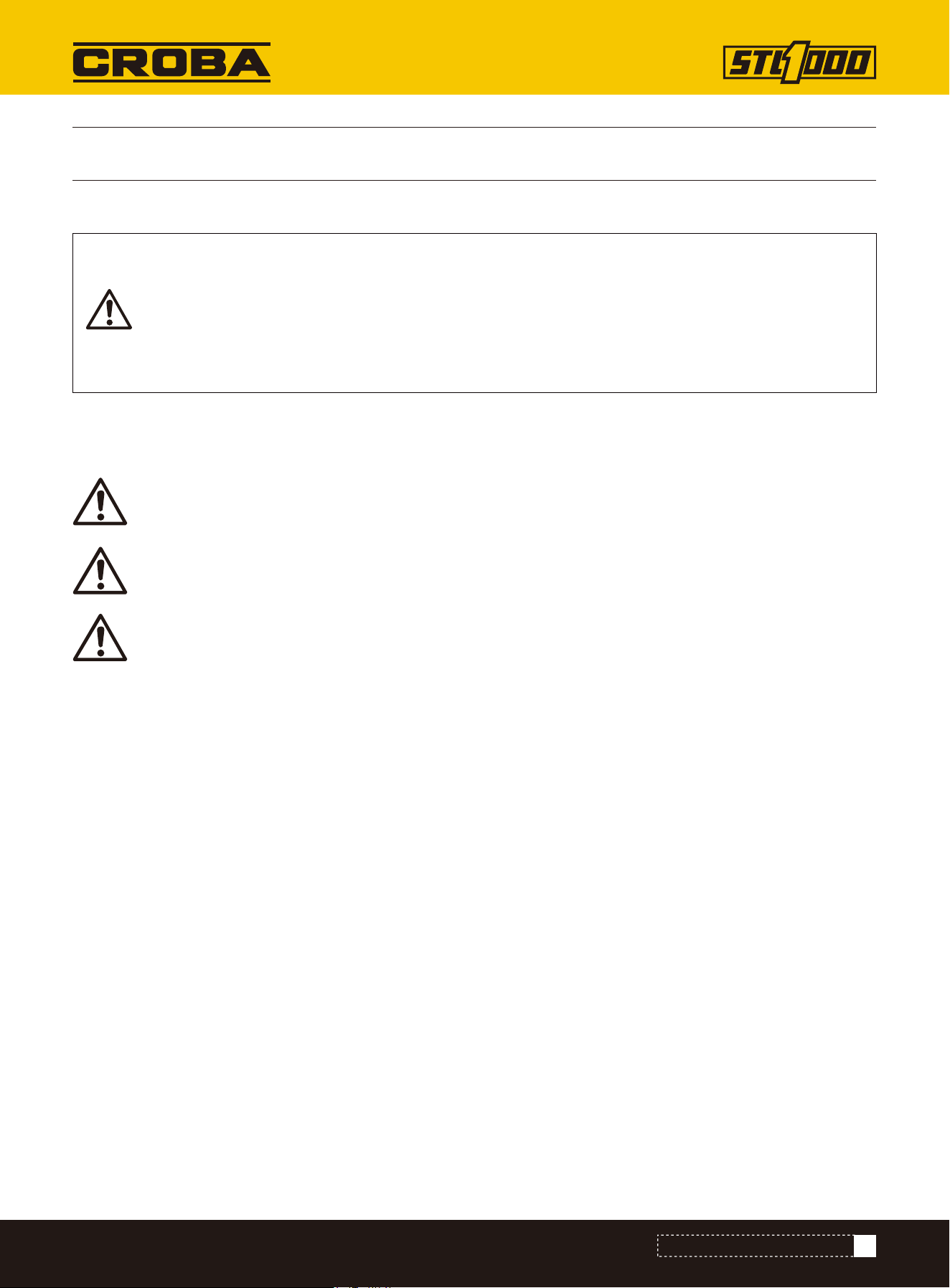
Be Aware of Signal Words
Look for the Safety Alert Symbol
A signal word designates a degree or level of hazard seriousness. The signal words are:
Be Aware of Special Notices
Special notices are intended to point out important and helpful information that should be followed. Types of special
notices are:
IMPORTANT:Indicates that failure to follow the warning may result in damage to or a breakdown of the equipment.
NOTE:Indicates supplementary explanations that will be helpful when using the equipment.
Safety at All Times
Careful operation is your best assurance against an accident.
All operators, no matter how much experience they may have, should carefully read this manual and other related
manuals, or have the manuals read to them, before operating the equipment.
• Thoroughly read and understand the “Important Safety Information” and “General” sections in this manual.
• Follow instructions noted on all safety labels.
• Do not operate the equipment while under the influence of drugs or alcohol, as they will impair the ability to safely
and properly operate the equipment.
• Service personnel and operators should be familiar with all functions of the equipment to be able to react quickly,
should an emergency arise.
• Keep hands, feet, and clothing away from power-driven parts.
Prepare for Emergencies
• Be prepared if a fire starts.
• Keep a first-aid kit and fire extinguisher close at hand for unexpected emergencies.
• Keep emergency contact information for doctors, hospitals and other emergency services such as the fire depart-
ment near a phone.
The SAFETY ALERT SYMBOL indicates there is a potential hazard to personal safety involved and extra
safety precaution must be taken. When you see this symbol, be alert and carefully read the message
that follows it. In addition to design and configuration of equipment, hazard control, and accident pre-
vention are dependent upon the awareness, concern, prudence, and proper training of personnel
involved in the operation, transport, maintenance, and storage of equipment.
SAFETY PRACTICES
Indicates a hazardous situation that, if not avoided, will result in death or serious injury.
DANGER
Indicates a hazardous situation that, if not avoided, could result in death or serious injury.
WARNING
Indicates a hazardous situation that, if not avoided, may result in minor or moderate injury.
CAUTION

6
IMPORTANT SAFETY INFORMATION
Wear Personal Protective Equipment (PPE)
• Wear protective clothing and equipment appropriate for the job such as safety shoes, safety glasses, hard hat, and
ear plugs.
• Clothing should fit snug without fringes and pull strings to avoid entanglement with moving parts.
• Prolonged exposure to loud noise can cause hearing impairment or hearing loss. Wear suitable hearing protection
such as earmuffs or earplugs.
• Operating equipment safely requires the operator’ s full attention. Avoid wearing headphones while operating equip-
ment.
Safe Practices for Preventing Fires
Keep all sources of ignition — such as acetylene or oxygen flames, welding sparks, grinding sparks, and lit ciga-
rettes — away from fuel and battery areas.
Note: The battery emits flammable hydrogen and oxygen gases.
Avoid High Pressure Fluids Hazard
• Escaping fluid under pressure will penetrate the skin or eyes causing serious injury.
• Relieve all residual pressure before disconnecting hydraulic lines or performing work on the hydraulic system.
• Make sure all hydraulic fluid connections are properly tightened/torqued and all hydraulic hoses and lines are in
good condition before applying pressure to the system.
• Use a piece of paper or cardboard, NOT BODY PARTS, to check for suspected leaks.
• Wear protective gloves and safety glasses or goggles when working with hydraulic systems.
• DO NOT DELAY. If an accident occurs, seek immediate emergency medical care or gangrene may result.
Avoid Battery Acid Burns
• Before attempting to work with the battery, perform a self check to ensure all the appropriate PPE and protective
clothing are being worn.
• Keep electrolyte away from eyes, hands and clothing. Sulfuric acid in battery electrolyte is poisonous and can burn
skin and clothing, as well as cause blindness.
• DO NOT DELAY. If an accident involving battery electrolyte occurs, thoroughly clean affected areas with water and
seek medical attention immediately.
Handle Chemicals Properly
• Protective clothing should be worn.
• Handle all chemicals with care.
• Follow instructions on container label.
• Agricultural chemicals can be dangerous. Improper use can seriously injure persons, animals, plants, soil, and prop-
erty.
• Inhaling smoke from any type of chemical fire can be a serious health hazard.
• Store or dispose of unused chemicals as specified by the chemical manufacturer.
• Obey related environmental protection regulations when discarding oil, fuel, coolant, electrolyte, and other hazard-
ous waste.
• Do not discard fluids to the ground, down the drain, into a stream, pond, or lake.
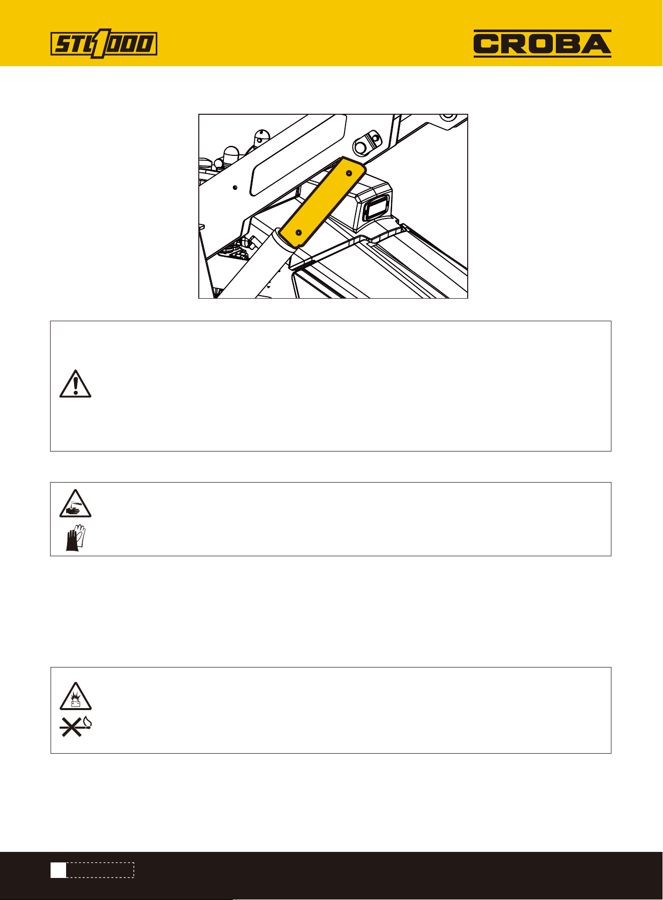
Clean up any spilled fuel immediately to reduce fire risk.
When disconnecting the battery, always remove the negative (-) terminal first.
When reconnecting the battery, connect the positive (+) terminal first.

7
IMPORTANT SAFETY INFORMATION
Starting the Engine
• Step onto the operator’s platform with both feet.
• Ensure the throttle is in the idle position.
• Place the red power switch into the [ON] position.
• Once prompted, use the buttons on the control monitor to enter passcode.
• Press middle button on control monitor to start the engine.
Practice Safe Maintenance
• Read and understand procedure before doing work.
• Work on a level surface in a clean dry area that is well-lit.
• Operate equipment and its controls only while standing on the Operator’s platform with both feet.
• Never dismount from the equipment while it is moving.
• Lower lift arms to the ground and follow all shutdown procedures before leaving the operator's seat to perform
maintenance.
• Once shutdown procedure is complete, hang a “DO NOT OPERATE” tag on the control panel.
• Do not work under any hydraulic supported equipment. It can settle, suddenly leak down, or be lowered accidental-
ly. If it is necessary to work under the equipment, securely support it with stands or suitable, non-concrete blocking
beforehand.
• Use properly grounded electrical outlets and tools.
• Use appropriate tools that are in good working condition for the job.
• Allow the equipment and its components to cool before performing maintenance work.
• Do not remove caps and plugs immediately after stopping the engine. The temperature and pressure of the coolant,
hydraulic oil and fuel will still be high.
• Be aware that when releasing hydraulic pressure, the machine or front attachment might move unexpectedly.
• Disconnect negative (-) battery cable before servicing or adjusting electrical systems or before welding on equip-
ment.
• Inspect all parts. Make certain parts are in good condition and installed properly.
• Replace parts on this attachment with genuine Kubota parts only. Do not alter this machine in a way which will
adversely affect its performance.
• Do not grease or oil attachment while it is in operation.
• Remove buildup of grease, oil, or debris.
• Always make sure any material and waste products from the repair and maintenance of the attachment are proper-
ly collected and disposed.
Starting the Engine
• Park on solid, level ground.
• Lower lift arms until they are flat on the ground.
• Reduce engine speed to idle.
• Shut off all auxiliary power to the attachment (if applicable).
• Allow the engine to run at idle speed for a few minutes.
• Press middle button on control monitor to stop the engine, then flip power switch to [OFF] position.
• Wait for all components to come to a complete stop before dismounting from the operator platform.
• Remove all tools and unused parts from the equipment before operation.
• To ensure your safety and the longevity of your machine, we recommend not holding a load at a lifting height for an
extended period of time.
8
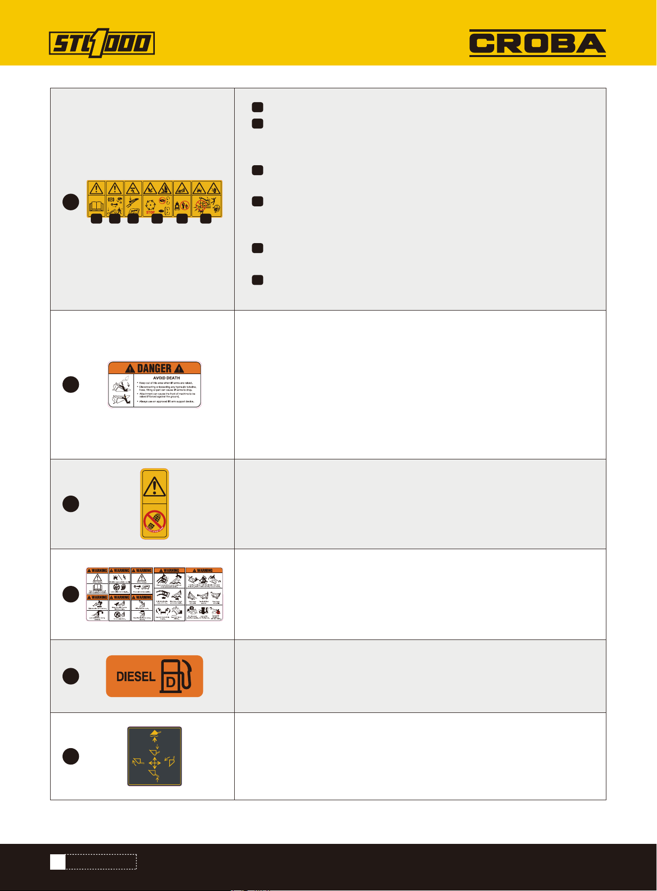
SAFETY LABELS
SAFETY LABELS
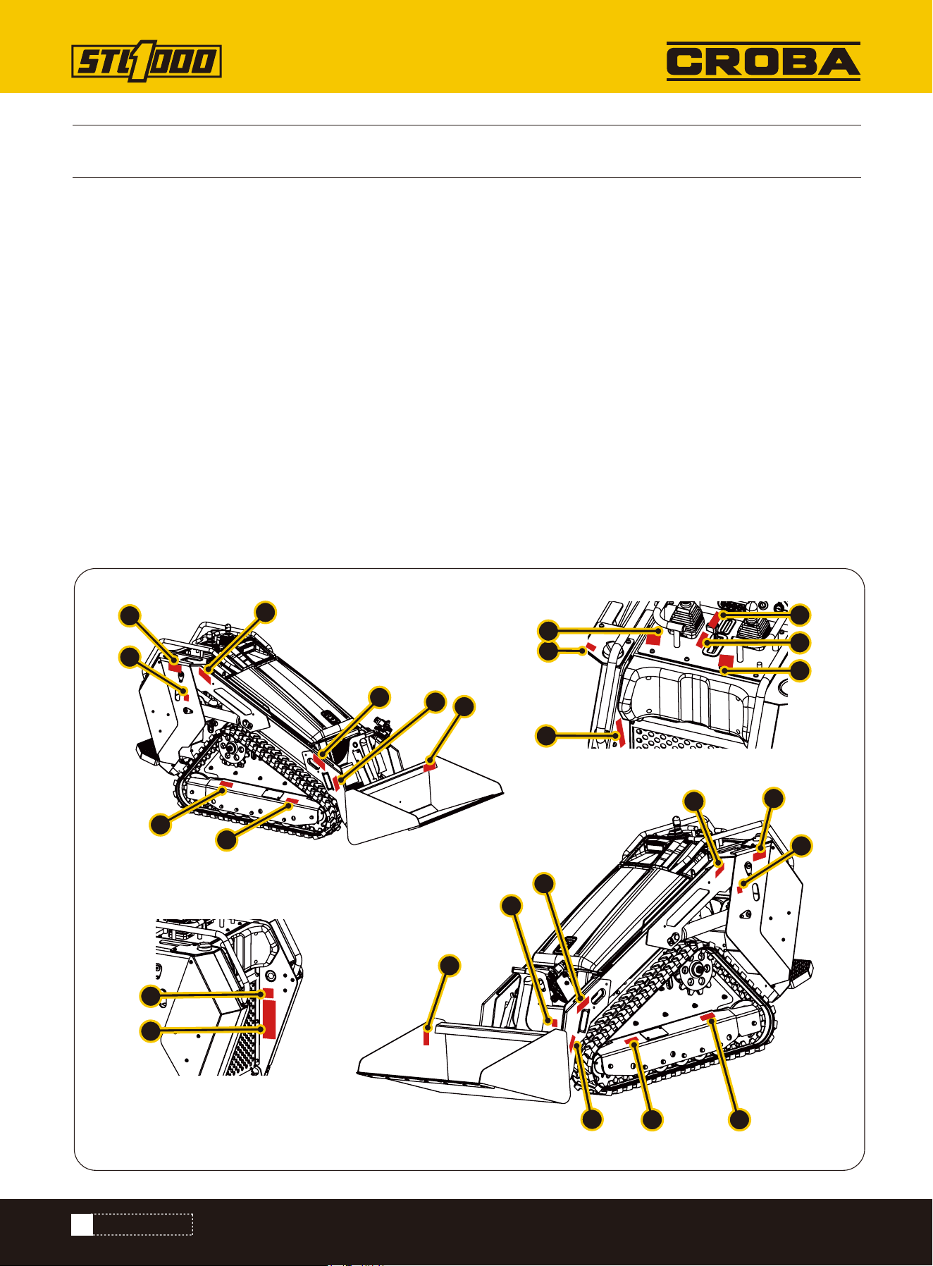
Label Placement
Safety Labels and Locations
The Stand-on Compact Loader comes equipped with all safety labels in place. They are designed to help you safely
operate the machine. Read and follow their directions.
• Keep all safety labels clean and legible.
• Refer to this section for proper label placement.
• Replace all damaged or missing labels.
• When ordering new components, make sure the correct safety labels are included in the request.
• To install new labels:
a. Clean surface area where label is to be placed.
b. Spray soapy water onto the cleaned area.
c. Peel backing from label and press label firmly onto the surface.
d. Squeeze out air bubbles with edge of a credit card or with a similar type of straight edge.
SAFETY AND INSTRUCTIONAL LABELS
6
7
6
11
11
2
1
2
3
4
5
1
9
5
7
12
5
8
10
13
14
16
15
17
18
9
SAFETY LABELS
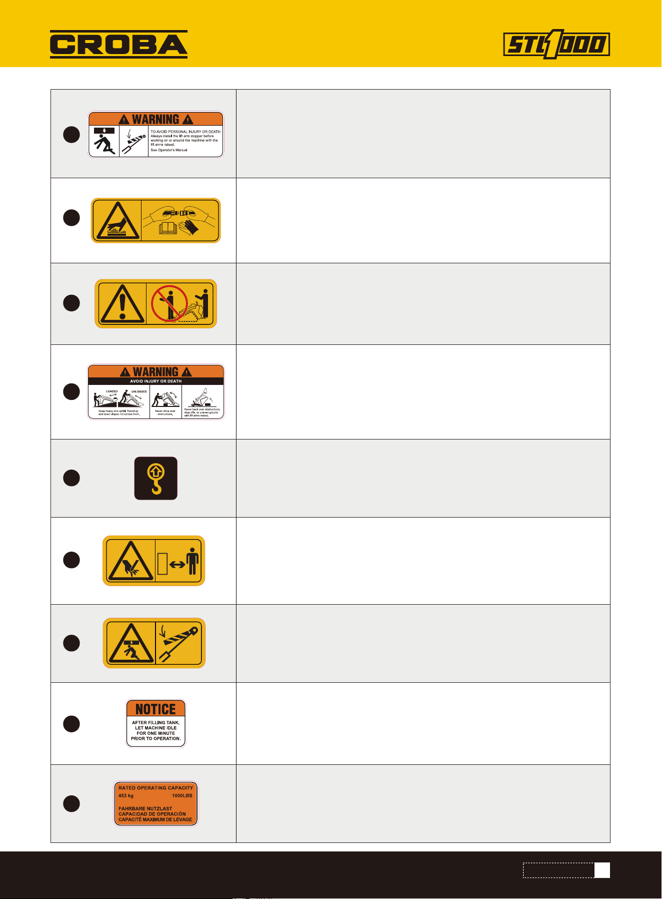
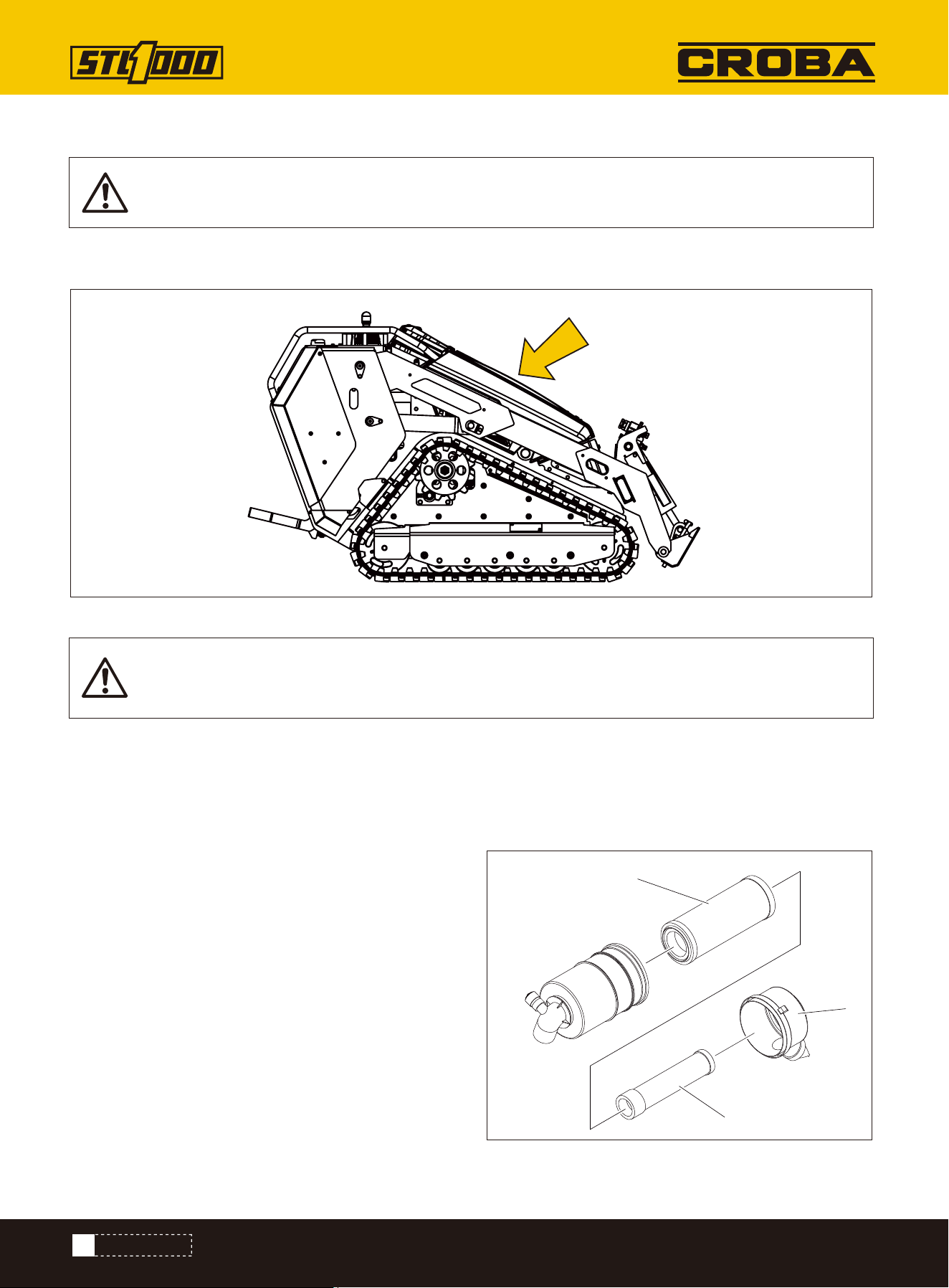
TO AVOID PERSONAL INJURY OR DEATH: Always install the lift arm support
before working on or around the machine with the lift arms raised.
See Operator's Manual
Hot surface/burn hazard—wear protective gloves when handling the
hydraulic couplers and read the Operator's Manual for information on
handling hydraulic components.
Keep heavy end uphill. Travel up and down slopes not across them.
Never back over obstructions, drop offs, or uneven ground with lift arms
raised.
Never drive over obstructions.
Raised component. Crushing can cause death or serious injury. Stay away
or secure raised component with locking device. Use correct equipment
and procedures.
After filling tank let machine idle for one minute prior to operation.
1000 LBS (453Kg) rated operating capacity.
Moving parts. Contract can cause serious injury. Stay away.
Lift point. See transport chapter for more information.
Crushing hazard—keep away from the attachment when operating the
machine; keep bystanders away from the machine.
1
2
3
4
5
6
7
8
9
10
SAFETY LABELS
Warning—read the Operator's Manual.
Warning—engage the parking brake, lower the attachment to the
ground, shut off the engine, and remove the key from the ignition
before leaving the machine.
Crushing hazard—keep away from pinch points; read the Operator's
Manual before servicing or performing maintenance.
Cutting/severing hazard of hand or foot—wait for all moving parts to
stop before servicing; keep away from moving parts; keep all guards
and shields in place.
Crushing hazard—keep away from the attachment when operating the
machine; keep bystanders away from the machine.
Explosion hazard; electrocution hazard—call the local utilities hotline
before beginning work in an area.
Keep out of this area when lift arms are raised.
Disconnecting or loosening any hydraulic tubeline, hose, fitting or part can
cause lift arms to drop.
Attachment can be forced against the ground and cause front of machine
to raise.
Always use an approved lift arm support device.
Abrupt movement and uneven terrain can throw operator off machine.
Traveling on slopes or with load elevated may result in tipover. Death or
serious crushing injury can result.
Fire and Fuel Hazard: Use Diesel fuel only. Keep ignition sources away.
Lift arm control.
Do not stand here.
1
2
3
4
5
10
6
11
12
13
14
15
1 2 3 4 5 6

11
SAFETY LABELS
Drive control instruction.
Engine speed.
Attachment drive control.
Keep out of this area when lift arms are raised.
16
17
18
19

12
PREPARE
PREPARE
To help avoid injury:
• Expose lines by careful hand digging or soft excavation before operating equipment. Use appropriate equipment and
procedures for exposing utility lines.
• Classify jobsite and follow precautions based on classification.
• Follow local regulations for digging near utilities.
A successful job begins before working. The first step in planning is reviewing information already available about the
job and jobsite.
Prepare Jobsite
• changes in elevation such as hills or open trenches
• obstacles such as buildings, railroad crossings, or streams
• signs of utilities
- “buried utility” notices
- gas or water meters
- drop boxes
- manhole covers
- utility facilities without overhead lines
- junction boxes
- light poles
- sunken ground
Review Job Plan
Review blueprints or other plans. Check for information about existing or planned structures, elevations, or proposed
work that may be taking place at the same time.
Select Start and End Points
Select one end to use as a starting point. Consider the following when selecting a starting point:
Slope
Equipment should be parked on a level site. Consider how slope will affect setup and operation. Assess the risks on
each slope to determine if factors affecting risks create an unsafe condition for working.
Space
Check that starting and ending points allow enough space for working.
Comfort
Consider shade, wind, fumes, and other site features.
Identify Hazards
Inspect jobsite before transporting equipment. Check for the following:
• overall grade or slope
Underground utilities. Contact can cause death or serious injury. Locate and verify underground
utilities before digging or drilling.

13
• traffic
• access
• soil type and condition
• loose material such as fencing or cable
Identify safety hazards and classify jobsite if attachment will penetrate ground.
Select a Classification
Jobsites are classified according to underground hazards present, not by line being installed. Jobsite may have more
than one classification.
Classify jobsite as electric if jobsite is in question or if the possibility of unmarked electric utilities exists.
Once classified, precautions appropriate for jobsite must be taken. Follow US Department of Labor regulations on
excavating and trenching (Part 1926, Subpart P) and other similar regulations.
Underground utilities. Contact can cause death or serious injury. Locate and verify underground
utilities before digging or drilling.
CLASSIFY JOBSITE
APPLY PRECAUTIONS
Within 10’ (3m) of a buried electric line
Electric
Within 10’ (3m) of a natural gas line
Natural gas
Crystalline silica dust
Within 10’ (3m) of any other hazard
Crystalline silica dust
In concrete, sand, or granite which is capable of pro-
ducing crystalline silica dust
If working . . . Then classify jobsite as . . .
PREPARE
14
Natural Gas Jobsite Precautions
Crystalline Dust Jobsite Precautions
Position equipment upwind from gas lines and use one or both of these methods:
• Expose line by careful hand digging or soft excavation.
• Have service shut down while work is in progress. Have gas company test lines before returning them to service.
Other Jobsite Precautions
You may need to use different methods to safely avoid other underground hazards. Talk with those knowledgeable
about hazards present at each site to determine which precautions should be taken or if job should be attempted.
Clear objects such as landscaping fabric, cable, and wire from the work area. These objects may be underground or
partially buried.
Arrange for Traffic Control
Vehicle and pedestrian traffic must be a safe distance from equipment. Evaluate jobsite and allow an appropriate
buffer zone around equipment. If working near a road or other traffic area, contact local authorities about safety pro-
cedures and regulations.
Crystalline silica dust is a naturally occurring substance found in soil, sand, concrete, granite, and quartz.
To reduce exposure when cutting, drilling, or working these materials:
• Use water spray or other means to control dust.
• Refer to US Occupational Safety and Health Administration (OSHA) guidelines or other applicable regulating guide-
lines for appropriate breathing protection or dust control methods.
Electric Jobsite Precautions
Use one or both of these methods:
• Expose line by careful hand digging or soft excavation.
• Have service shut down while work is in progress. Have electric company test lines before returning them to ser-
vice.
Jobsite hazards. Exposure can cause death or serious injury. Use correct equipment and work
methods. Use and maintain appropriate safety equipment.
Silica dust. Exposure can cause lung disease or cancer. Use breathing protection.
Prepare Operator
To help avoid injury:
• Wear personal protective equipment including hard hat, safety eye wear, foot protection, hearing protection, and
gloves (except when near rotating equipment).
• Remove jewelry.
• Wear close-fitting, high visibility clothing.
• Have other personal protective equipment, such as insulated boots and gloves, breathing protection, and face
shield, etc. available for use depending on jobsite hazards or requirements.
PREPARE
15
Check Supplies
• Fuel
• Marking flags or paint
• Notepad and pencil
• Spare fuses
• Lubricants
Assemble Accessories
If required, mount fire extinguisher near the power unit but away from possible points of ignition. The fire extinguish-
er should always be classified for both oil and electric fires. It should meet legal and regulatory requirements.
1.Position attachment on level surface with enough space behind it to accommodate machine.
2.Start engine.
Follow these guidelines before operating any jobsite equipment:
• Complete proper training and read Operator’s manual before using equipment.
• Plan for emergency services. Have the telephone numbers for local emergency and medical facilities on hand.
Check that you will have access to a telephone.
• Review jobsite hazards, safety and emergency procedures, and individual responsibilities with all personnel before
work begins.
• Use equipment carefully. Stop operation and investigate anything that does not look or feel right.
• Battery
• Hoses and valves
• Pumps and motors
• Tires or tracks
• Signs, guards, and shields
• Filters (air, oil, hydraulic, fuel)
• Belts
IMPORTANT: Before connecting attachment to machine, ensure that attachment and receiver
plates are free of dirt and debris.
Improper control function. Use can cause death or serious injury. If control does not work as described
in instructions, stop machine and have it serviced.
PREPARE EQUIPMENT
Fluid Levels
• Fuel
• Engine oil
• Hydraulic fluid
• Engine coolant
Condition and Function
• All controls
CHECK EQUIPMENT
NOTICE: Attachments can change the stability and operating characteristics of the machine. See
attachment operation manual for instructions regarding proper operation of attachments.
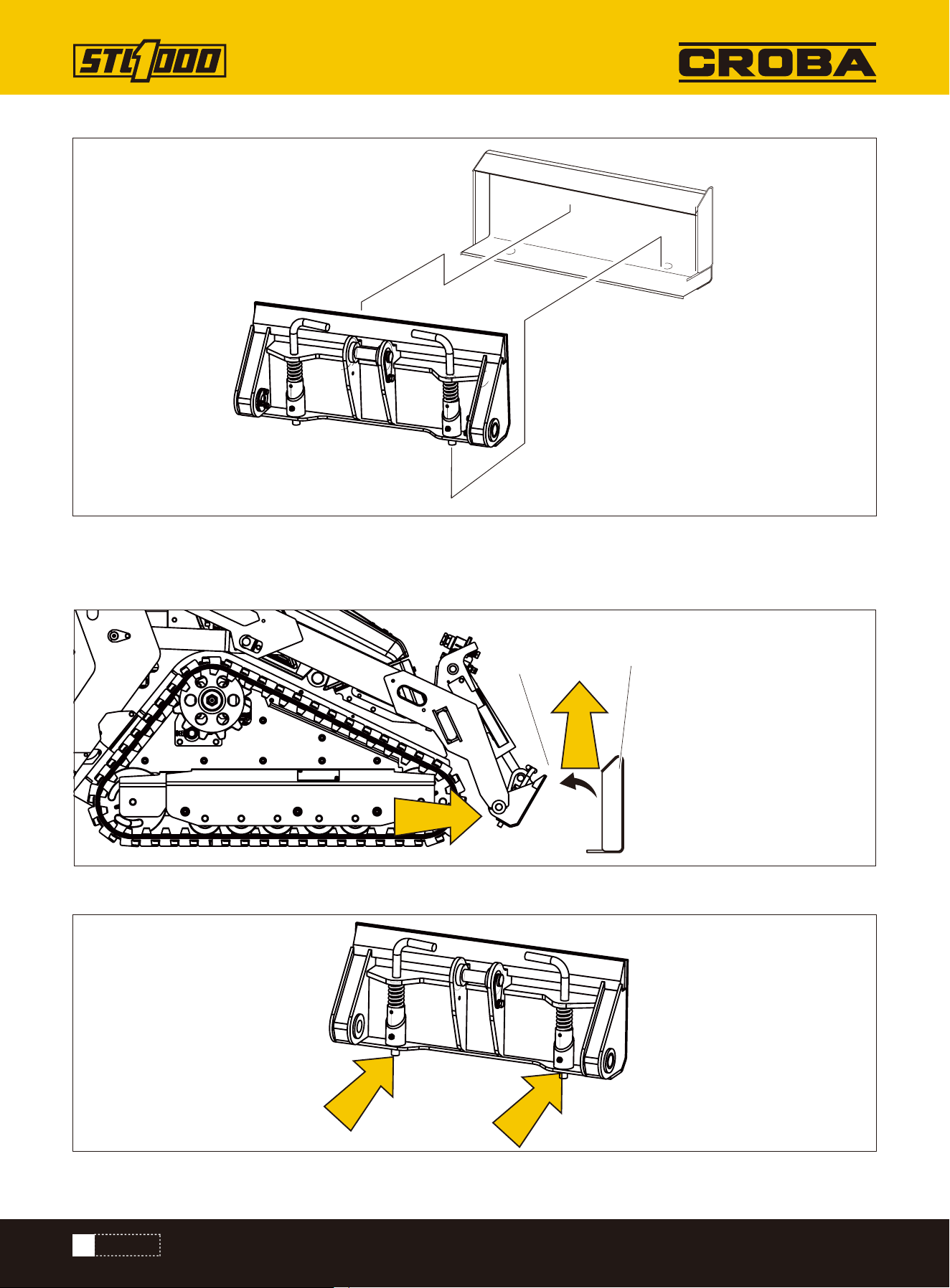
Connect Attachment
PREPARE
16
6. Ensure pins are engaged by rotating attachment down.
3. Tilt attachment plate (2) forward.
4. Position attachment plate in upper lip of receiver plate (1) on attachment.
5. Raise lift arms while tilting back attachment plate to engage pins.
1
2
PREPARE
17
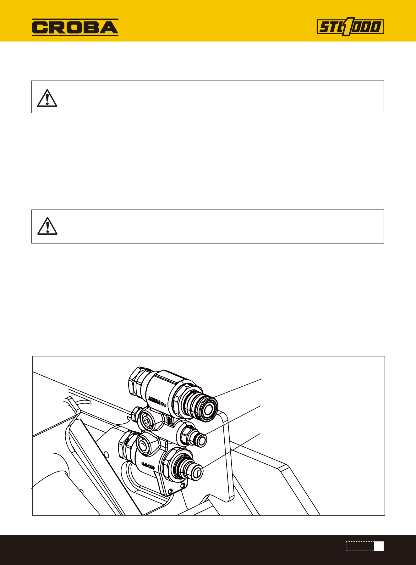
If attachment requires hydraulic power for operation, connect hydraulic hoses.
To help avoid injury:
• Use a piece of cardboard or wood, rather than hands, to check for leaks.
• Before disconnecting a hydraulic line, turn engine off and operate all controls to relieve pressure.
• Lower, block, or support any raised component with a hoist.
• Cover connection with heavy cloth and loosen connector nut slightly to relieve residual pressure.
Catch all fluid in a container.
• Before using system, check that all connections are tight and all lines are undamaged.
• If you are injured, seek immediate medical attention from a doctor familiar with this type of injury.
1.Ensure machine is shut off.
2.Activate accessories using ignition switch.
3.Operate auxiliary controls to relieve residual pressure at hydraulic couplers.
4.Remove dirt and debris from hydraulic couplers.
5.Connect male coupler from attachment to female coupler (3) on machine.
6.Connect female coupler from attachment to male coupler (1) on machine.
7.If needed, connect attachment case drain hose to
case drain connector (2).
8.Ensure that connections are secure by pulling on hoses.
HYDRAULIC CONNECTION
Pressurized fluid or air. Injection can cause death or serious injury. Refer to operator’ s manual for
correct use.
Hot parts. Contact can cause burns. Only touch when cool or wear gloves.
1
2
3
PREPARE
18
There are additional noise emissions and high noise levels in the workplace.
Exposure can cause hearing loss.
Wear hearing protection.If you are injured, seek immediate medical attention from a doctor
familiar with this type of injury.
warning, in some specific operating conditions of the machine, the actual noise emission may be
different from the values determined using the noise test code;
NOISE EMISSION
PREPARE
19
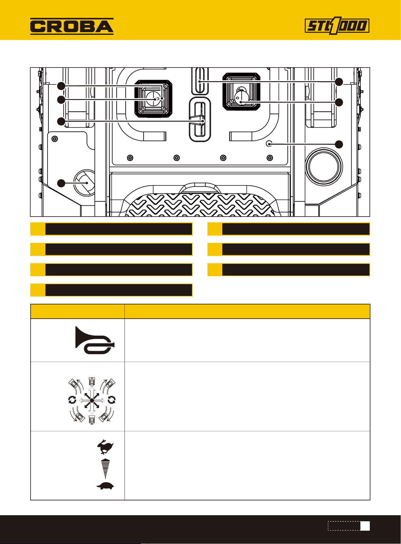
CONTROLS
CONTROLS
3
1
7
8
9
2
4
5
6
1
2
3
4
5
6
7
8
9
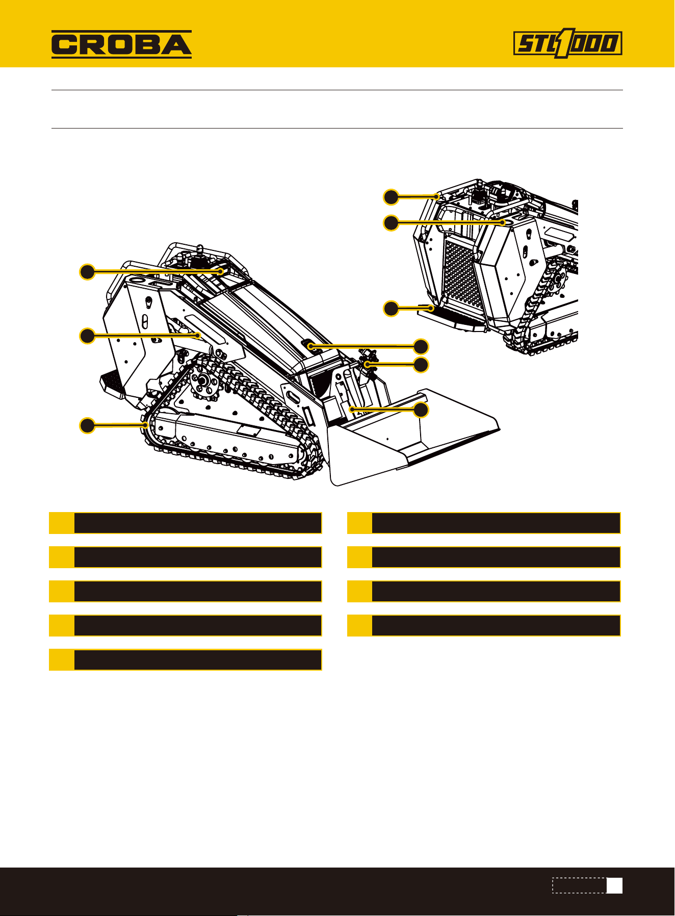
APPENDAGE OIL CYLINDER
OIL FILTER
CUP HOLDER
STAND PEDAL
FRONT LIGHT
LIFTING ARM
TRACK
HOOD LOCK
QUICK CHANGE JOINT
20
CONTROLS
1
2
3
4
6
7
8
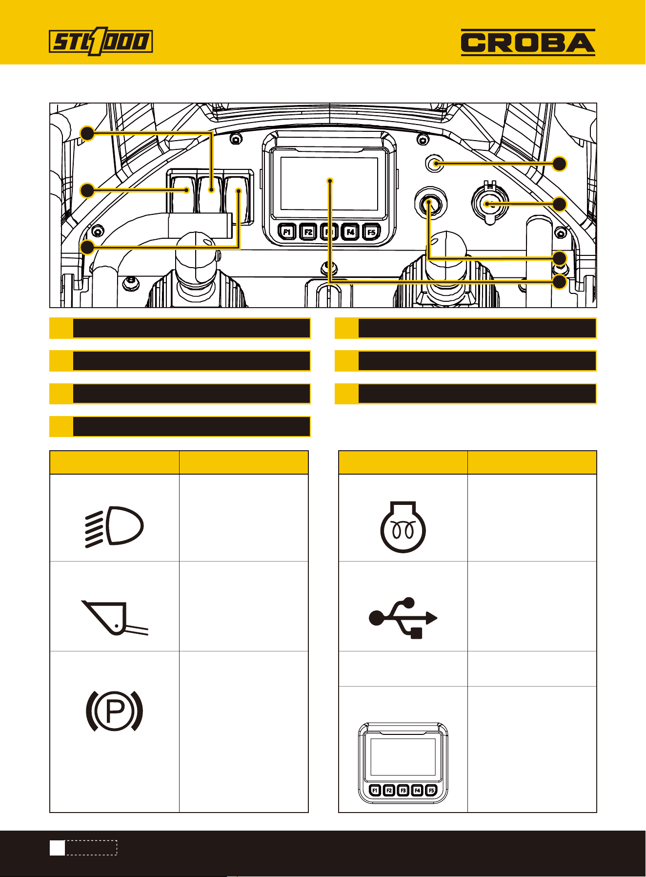
1.
Front light button
4.
Engine glow
2.
Lifting Arm Down
5.
USB charging
6.
Switch Lock
7.
Display
3.
Park
Press to turn on the
light
Lights when ignition
switch is on and glow
plug button is pressed.
Display machine usage
data
Charging
Start
When pressed, the
lifting arm will
automatically lower
Press to start parking.
Be careful not to use
parking while moving
FRONT LIGHT
LIFTING ARM DOWN
PARK
ENGINE GLOW
USB CHARGING
SWITCH LOCK
DISPLAY
Gauges and Indicators
1
5
4
2
3
6
7
Item ItemDescription Description
21
CONTROLS
1
2
3
4
6
7
8
HORN
STEERING
THROTTLE
DIESEL
ATTACHMENT DRIVE CONTROL
BOOM ARM
SAFETY ROPE
Operator Station
4
3
2
5
6
7
1
1.
Horn
2.
Steering
3.
Throttle
Horn button on the right side, honk after pressing
Drive forward and push the lever forward
Drive backwards and push the lever back
Drive left and push the lever forward left
Drive to the right and push the lever forward to the right
Turn around and push left or right
To increase engine speed, push.
To decrease, pull.
Item Description
22
CONTROLS
4.
Diesel
5.
Attachment drive control
6.
Boom Arm
Diesel port
To engage attachment drive in reverse, push.
To engage in forward, pull.
To move lift arms down, push.
To float, push to end.
To move lift arms up, pull.
To curl attachment up, move left.
To curl attachment down, move right.
Safety rope, connect with the driver, if the driver accidentally falls, drag the
safety rope, safety rope will make the machine trigger emergency stop,
improve safety
Item Description
7.
Safety Rope
23
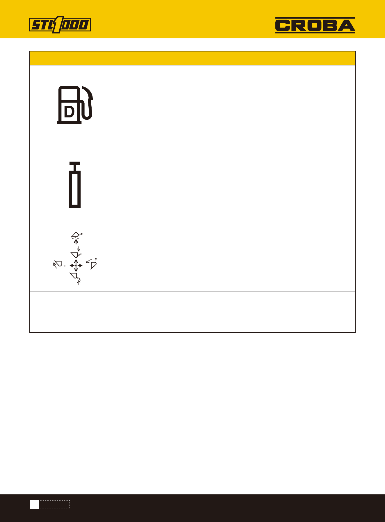
CONTROL MONITOR
CONTROL MONITOR
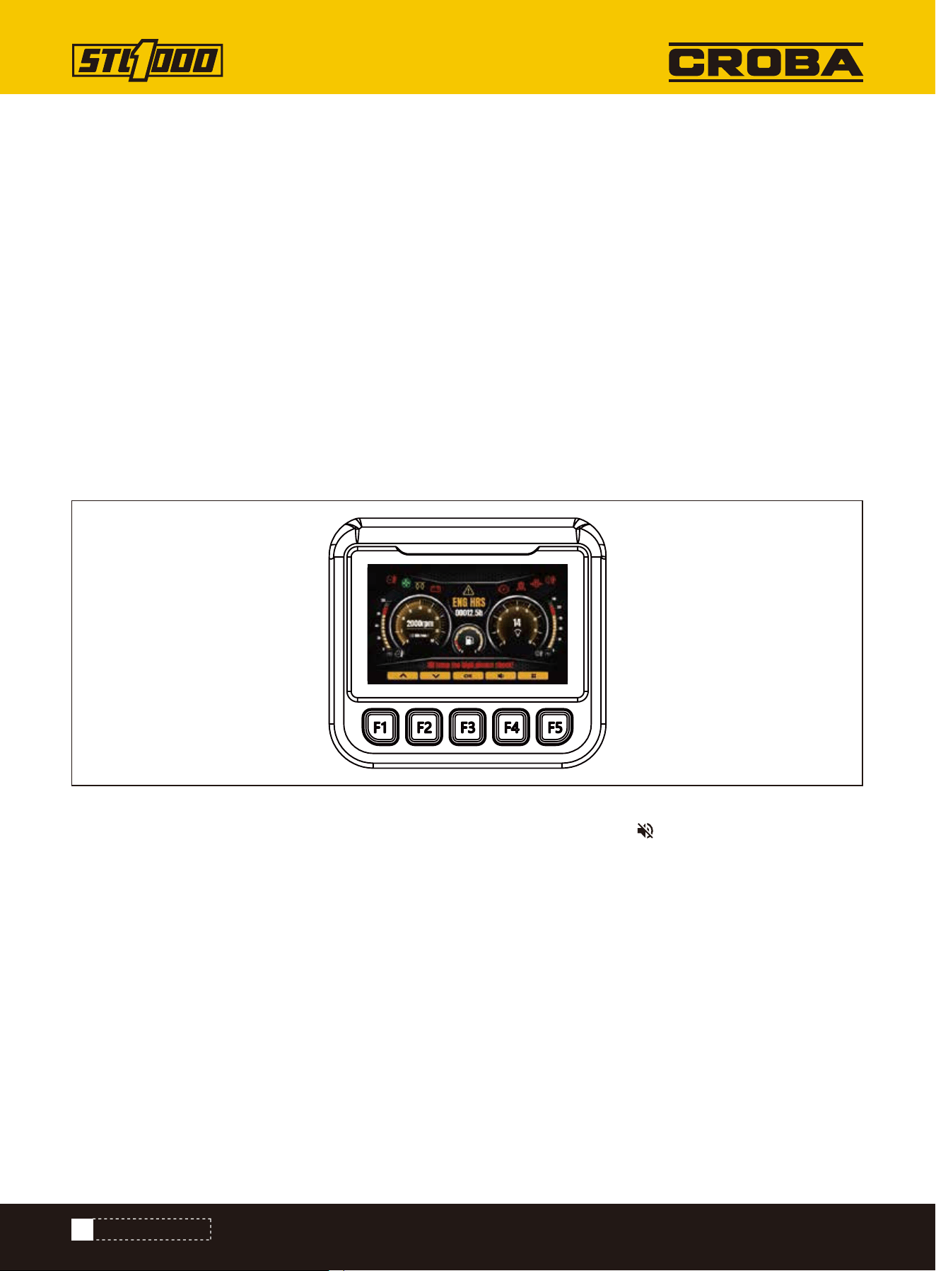
Main interface introduction
Alarm information display area
The monitor main interface mainly contains alarm icon, pointer dial, text alarm display, working status, working time
and other information. The details are as follows:
When the machine is started, the control monitor automatically starts.
CONTROL MONITOR STARTUP
The LCD monitor is equipped with a waterproof cover. Please don't remove the cover to avoid com-
promising its seal, which may result in water damage to the screen.
24
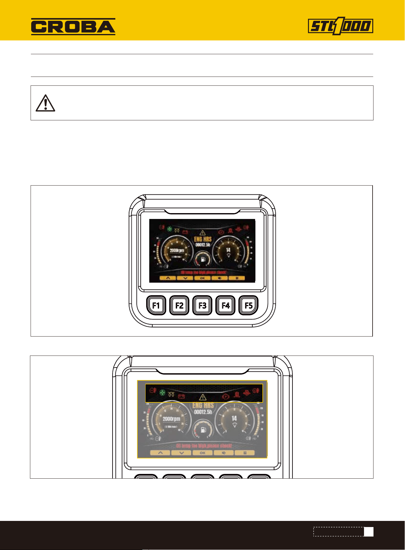
CONTROL MONITOR
Dashboard display area
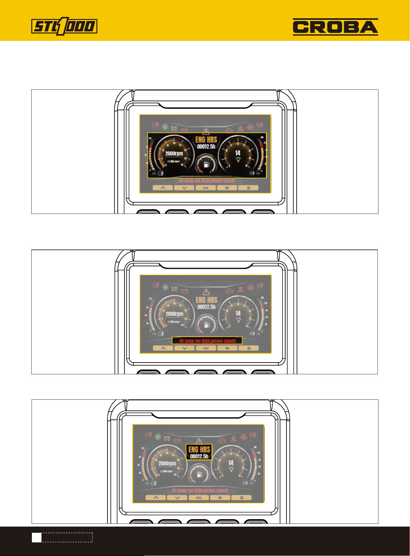
Text alarm area
Instrument panel display area: Water temperature, speed, fuel level, voltage, hydraulic oil temperature display area
from left to right.
Displays current important fault alarms, such as engine water temperature, oil pressure, etc.
Alarm information display area: the upper left side shows the alarm icon, from left to right are water temperature,
fan, preheating, charging, fault, parking brake, hydraulic oil filter blockage, oil pressure, hydraulic oil temperature, etc.
Working time display

25
The interface includes vehicle information, user settings, system settings, instrument management and other four
contents.
Instrument operating time display.
Indicates the function corresponding to the key on the current page
Key functional area
State
LOCATE UTILITIES
Press the directory key on the home screen to access the system menu selection screen.
Adjust the menu cursor position
Adjust the menu cursor position
Confirm key, go to the submenu of the next level
Return key to return to the main interface
Through the system menu, press the key, select State, and press the Confirm key to enter the vehicle status
interface. In this interface, you can view the status parameters of the current vehicle: system voltage, water tem-
perature, oil temperature, oil level, speed, etc
CONTROL MONITOR

26
Select the "user" option and press the "Confirm" key to enter the boot password to enter the user Settings screen, on
which you can set whether to enable the boot password login, you can change the boot password.
(Default user login password 1418)
User
Modify the number of the current cursor
Modify the number of the current cursor
Move cursor position
Confirm password input
Return to upper level
CONTROL MONITOR

27
Water temperature data display and alarm
The monitor can collect water temperature information in real time and display it through the pointer instrument. The
pointer is displayed in the dashboard display area of the main interface. The specific temperature values are dis-
played in the locomotive parameters option.
1, The water temperature is too high alarm temperature of 102 ° C (215.6°F).
When the water temperature is below 102 ° C (215.6°F):
The water temperature icon remains green, and the water temperature pointer points to the appropriate scale in the
dial display area.
When the water temperature is above 102 ° C (215.6°F):
1.When the engine is not working, the water temperature alarm icon is always green and does not blink.
Water temperature pointer to red alarm zone. Text alarm display area appears "engine water temperature is too high,
please stop immediately check!".
2.When the engine is working, the water temperature alarm icon changes from green to red and flashes the alarm.
Water temperature pointer to red alarm zone.
Text alarm display area appears "engine water temperature is too high, please stop immediately check!" Alarm, and
buzzer alarm.
The following contents are included in the data collection display: water temperature, oil temperature, speed signal,
oil pressure, preheating, generator signal, pressure signal, battery voltage, etc.
DATA ACQUISITION DISPLAY
Whether to enable the power-on password
Changing the boot Password
Return to upper level
Text alarm display area appears "engine water temperature is too high, please stop immediately check!" Alarm,
and buzzer alarm.
1.When the engine is not working, the water temperature alarm icon is always green and does not blink. The water
temperature pointer points to the leftmost part of the water temperature dashboard. Text alarm display area
appears "water temperature sensor circuit short circuit, please check!".
2.When the engine is working, the water temperature alarm icon changes from green to red and flashes the alarm.
The water temperature pointer points to the leftmost part of the water temperature dashboard. At this time, the
text alarm display area appears "short circuit of water temperature sensor line, please check!" Alarm, and buzzer
alarm.
The water temperature sensor circuit is faulty
CONTROL MONITOR
28
Sound off
The monitor has the function of speed detection and display, which is displayed on the main interface. If there is no
speed signal, when the engine is working, the text alarm display area will appear "No speed alarm detected!" When
the engine is not working, there is no speed alarm information.
Speed signal display and alarm
It has the function of detecting whether the oil pressure is normal.
Under normal conditions, the monitor is powered on, the oil pressure alarm icon appears in the alarm information dis-
play area, and the oil pressure alarm icon does not blink at this time. When the engine starts, the oil pressure alarm
icon disappears.
When the oil pressure sensor is abnormal, the monitor is powered on, and the text alarm display area appears "Abnor-
mal oil pressure sensor alarm, please check immediately!" When the engine starts, the oil pressure icon flashes to
alarm. Text alarm display area appears "oil pressure sensor abnormal alarm, please check immediately!" Alarm, and
buzzer alarm.
In the process of working, when the monitor collects the signal of low oil pressure, the oil pressure icon flashes
alarm, and the text alarm area will appear "engine oil pressure is too low, please stop and check immediately!" Alarm,
and buzzer alarm.
Oil pressure alarm
When the buzzer alarms, press F4 on the main interface to display the mute mark , which can turn off the buzzer
alarm sound. Press F4 again to unmute the function.
CONTROL MONITOR
29
DRIVE
DRIVE
Start
Steer
Single Joystick Ground Drive
To help avoid injury:
• Allow hydraulic fluid time to warm before operating in cold weather. Cold hydraulic fluid can lengthen ground drive
stopping time.
• For starting in extreme temperatures, contact your dealer.
NOTICE: If engine turns but does not start within 10 seconds, allow starter to cool. Wait at least 30 seconds and try
again.
1.Ensure all controls are in neutral.
2.Set parking brake.
3.Activate accessories using ignition switch.
4.If starting machine in normal conditions, start engine and run at low throttle under light load for at least one
minute before applying heavier load.
If starting machine in cold weather:
1.Start engine.
2.Set parking brake.
3.Warm engine and hydraulic fluid by gradually increasing engine speed for up to 30 minutes.
4. After warmup, carefully operate all hydraulic controls at low throttle until controls operate as described in con-
trols chapter.
To steer while moving forward, push joystick and then move left or right. Machine will gradually turn.
To steer while moving in reverse, pull joystick and then move left or right. Machine will gradually turn.
For tight steering at low speed, release joystick and then move left or right. Tracks will counter-rotate and machine
will turn in a tight circle.
Misuse of machine can cause death or serious injury. Read and understand Operator’s manual and
all other safety instructions before use.
Pre-heater. Fire or explosion can cause death or serious injury. Never use starter fluid.
EMERGENCY SHUTDOWN: Shut off machine
30
DRIVE
Dual Control Ground Drive
To steer while moving forward, move one control slightly more than the other to turn in desired direction.
Machine will gradually turn.
To steer while moving in reverse, move one control slightly more than the other to turn in desired direction.
Machine will gradually turn.
For tight steering at low speed, pull one control and push the other to turn in desired direction. Tracks will count-
er-rotate and machine will turn in a tight circle.
EMERGENCY EXIT: Release controls and step off platform.
1.Release parking brake.
2.Raise attachment off ground.
3.Drive machine.
4.Adjust throttle as needed.
5.See the attachment’s operation manual for instructions regarding proper operation of attachments.
To help avoid injury:
• Operate at slow speed when on rough terrain.
• Avoid driving across slopes.
• Never jerk control levers. Use a steady, even motion.
• Always operate with heavy end uphill.
• Always drive with attachment low to the ground.
Tipover. Crushing can cause death or serious injury. Follow procedure in operator’ s manual. Drive
cautiously.
NOTICE:
• Drive carefully in congested areas. Know machine’s clearance and turning radius.
• Survey field of vision when operating machine.
Operate
Slope Guidelines
Operating safely on a slope depends upon many factors including:
• distribution of machine weight, including front loading and absence of load
• height of load
• even or rough ground conditions
• potential for ground giving way causing unplanned tilt forward, reverse or sideways
• nearness of ditches, ruts, stumps or other obstructions and sudden changes in slope
• speed
• turning
• braking performance
• operator skill
31
DRIVE
Rubber tracks are best suited at soil-based jobsites with minimal rocks and debris. To reduce track wear drive
slowly and make wide turns. Avoid the following:
• spinning tracks under heavy load
• turning on sharp objects such as stones, broken concrete, or debris
• quick turns on asphalt or concrete
• driving over curbs or ledges
• driving with track edges pressed against hard walls or curbs
• operating on corrosive materials such as salt or fertilizer
1.When job is complete, move machine to level ground.
2.Stop machine movement.
3.Set parking brake.
4.Lower lift arms to ground.
5.Return all controls to neutral.
6.Run engine at low throttle with no load for at least five minutes to cool.
7.Shut off machine.
8.If leaving machine unattended, remove key.
9.For maintenance or long-term storage, disconnect battery using battery disconnect switch.
These varying factors make it impractical to specify a maximum safe operating angle in this manual. It is therefore
important for the operator to be aware of these conditions and adjust operation accordingly. Maximum engine angle
and braking performance are two absolute limits which must never be exceeded. These maximums are stated
below since they are design limits. These design limits usually exceed the operating limits and must never be used
alone to establish safe operating angle for variable conditions.
Maximum engine lubrication angle: 20°
Maximum service brake retarding force: equal to traction of both tracks
Maximum parking brake holding force: equal to traction of one track
NOTICE: Wait two minutes after shutting off machine before disconnecting battery.
Reduce Track Wear
Shut Down
32
TRANSPORT
TRANSPORT
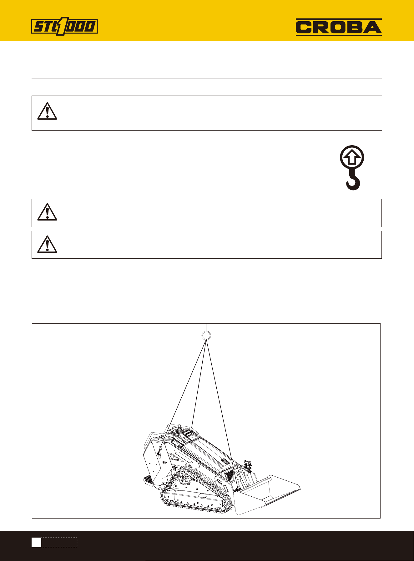
To help avoid injury: Only lift unit without attachment installed.
Use a equipment capable of supporting the machine's size and weight. See “Specifications” on page 3 or measure
and weigh equipment before lifting.
Use one of the methods below:
• Use two lift points nearest operator station.
• Use three lift points as shown.
Lifting points are identified by lifting decals. Lifting at other points is unsafe and can damage ma-
chinery.
Start
Points
Procedure
Lifted load. Crushing weight can cause death or serious injury. Stay away from lifted load and its
range of movement.
IMPORTANT: Do not lift machine with attachments installed.
IMPORTANT: Front of unit will be lower than rear.
33
TRANSPORT
Misuse of machine can cause death or serious injury.
Read and understand operator’s manual and all other safety instructions before use. Know how to use all controls.
To help avoid injury:
• Read trailer operator’s manual before loading or transporting machine.
• Ensure tow vehicle has proper tow capacity rating.
• Attach trailer to vehicle before loading or unloading.
• Load and unload trailer on level ground.
• To help prevent trailer sway, load trailer so that 10-15 percent of total vehicle weight (equipment plus trailer) is on
tongue.
• If loading onto tilt-bed trailer, be prepared for trailer to tilt.
Haul
Load
Lifted load. Crushing weight can cause death or serious injury. Stay away from lifted load and its
range of movement.
To help avoid injury: Start and operate only from platform.
1.Release parking brake.
2.Start engine.
3.Move throttle to low speed.
4.Raise attachment clear of trailer, but keep it low.
5.Move machine to rear of trailer and align with ramps.
6.Drive forward slowly to move machine onto trailer until tiedown position is reached.
7.Lower attachment to trailer bed.
8.Set parking brake.
9.Ensure all controls are in neutral position.
10.Shut off machine.
11.Tie down machine.
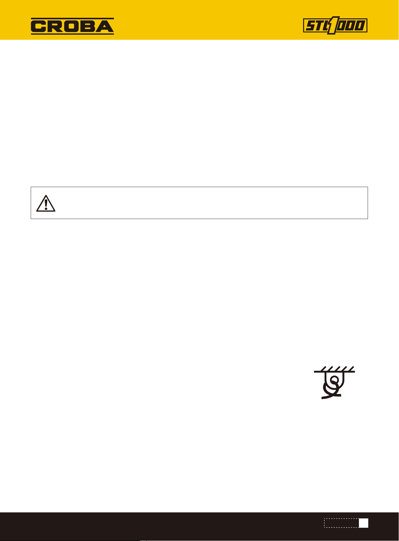
Tiedown points are identified by tiedown decals. Securing to truck or trailer at other points
is unsafe and can damage machinery.
Loop a transport chain around each tie down point. See chart below for correct distances between tiedown ends.
Ensure tiedowns are tight before transporting.
Tie Down Points
Procedure
34
TRANSPORT
Horizontal movement. Crushing can cause death or serious injury. Read and understand operator’s
manual and all safety instructions before use.
Under normal conditions, machine should not be towed.
If machine breaks down and retrieval is necessary:
Retrieve
• Tow for no more than 100’ (30m) at less than 1mph (1.6km/h).
•Use towing chains appropriately rated for maximum towing force.
•Use maximum force of 1.5 times machine weight.
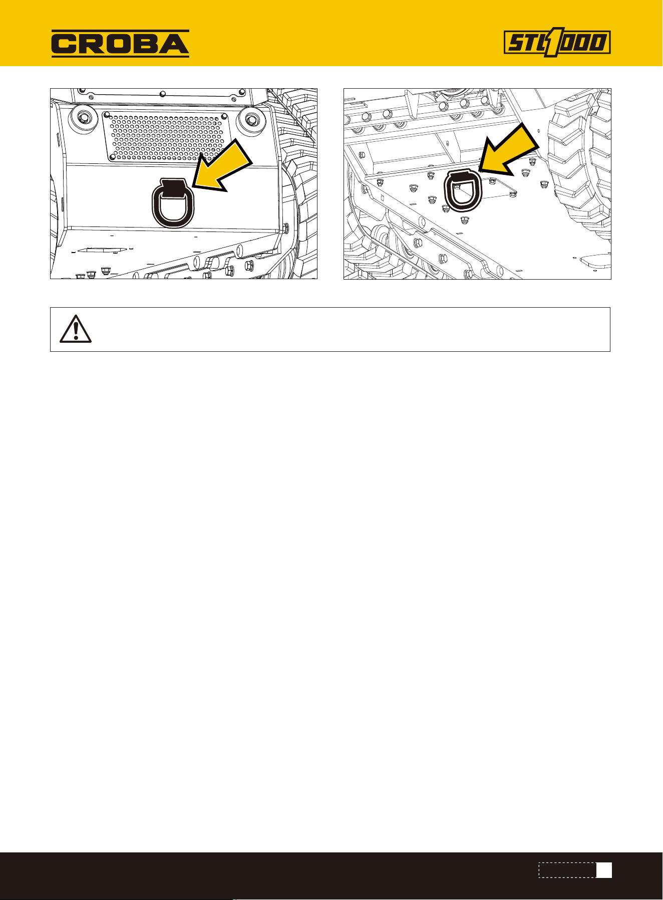
1.Set parking brake if engine will start.
2.Block tracks to prevent machine from rolling.
3.Attach chain to tow points shown facing towing vehicle.
Retrieve
Unload
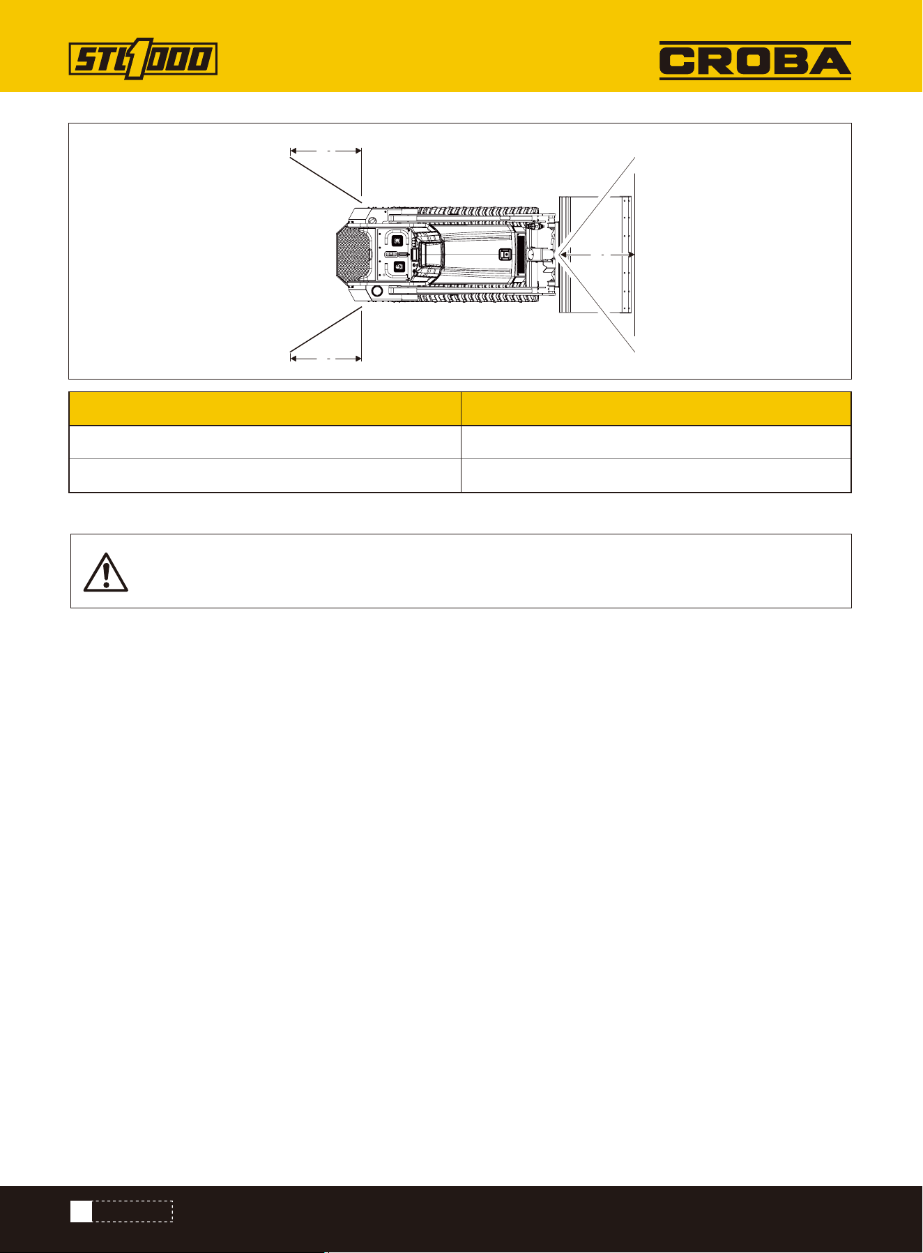
Distance
Metric
A1
A1
A2
To help avoid injury: Start and operate only from platform.
1.Prepare trailer and ramps for unloading.
2.Remove tiedowns.
3.Start engine.
4.Release parking brake.
5.Raise attachment off ground, but keep it low.
6.Move throttle to low speed and slowly back machine down trailer or ramps.
A1 7.9–29.9 in (20-76 cm)
A2 11.8–40.2 in (30-102cm)
35
TRANSPORT
NOTICE: When bypass valves are open, only parking brake functions.
4. Activate tow valves on both front and rear pumps by turning levers into position shown.
5. Remove blocks.
6. Release parking brake if engine will start. If engine will not start, remove rear panel and unbolt parking brake
assembly.
7. After towing, turn levers to operating position.

36
COMPLETE THE JOB
COMPLETE THE JOB
1.Spray water onto equipment to remove dirt and mud.
2.Remove mud from track sprockets.
3.Wash undercarriage.
1.Lower attachment to the ground.
2.Shut off machine.
3.Disengage lock pins by lifting handles upward.
4.Disconnect hydraulic hoses, if used.
5.Start engine.
6.Tilt mount plate forward and back machine away from attachment.
NOTICE:
• Do not spray water onto operator’ s console or electrical center in engine compartment. Water can
damage electrical components. Wipe down instead.
• Ensure all mud and debris is rinsed from tracks before parking unit overnight.
Rinse Equipment
Disconnect Attachment
Ensure all tools and accessories are loaded and properly secured on trailer.
Stow Tools

37
MAINTENANCE
MAINTENANCE
To help avoid injury:
• Wear personal protective equipment including hard hat, safety eye wear, foot protection, hearing protection, and
gloves (except when near rotating equipment).
• Remove jewelry.
• Wear close-fitting, high visibility clothing.
• Have other personal protective equipment, such as insulated boots and gloves, breathing protection, and face
shield, etc. available for use depending on jobsite hazards or requirements.
To help avoid injury:
• Unless otherwise instructed, all service should be performed with the engine off and cool.
• Lower unsecured, raised components before servicing equipment.
• Unless otherwise instructed, all service should be performed with machine parked on level surface.
• Refer to US Occupational Safety and Health Administration (OSHA) guidelines for appropriate lockout-tagout proce-
dures.
NOTICE: Do not spray water onto operator's console or electrical center in engine compartment. Water can damage
electrical components. Wipe down instead.
• Welding currents can damage electronic components. Always disconnect the ECU ground connection from the
frame, harness connections to the ECU, and other electronic components prior to welding on machine or attach-
ments.
• Connect welder ground close to welding point and make sure no electronic components are in the ground path.
• Disconnect battery at battery disconnect switch before welding to prevent damage to battery.
• Never turn off battery disconnect switch with engine running, or alternator and other electronic equipment devices
may be damaged.
Jobsite hazards. Exposure can cause death or serious injury. Use correct equipment and work
methods. Use and maintain appropriate safety equipment.
Misuse of machine can cause death or serious injury. Read and understand operator’s manual and
all other safety instructions before use. Know how to use all controls.
Raised component. Crushing can cause death or serious injury. Stay away or secure raised compo-
nent with locking device. Use correct equipment and procedures.
NOTICE: Welding can damage electronics.
Maintenance Precautions
Working under Raised Lift Arms
Washing Precaution
Welding Precaution
38
MAINTENANCE
Pin safety supports as shown when working under raised lift arms.
Before attempting to work with the battery, perform a self check to ensure all the appropriate PPE and protective
clothing are being worn.
• Keep electrolyte away from eyes, hands and clothing. Sulfuric acid in battery electrolyte is poisonous and can
burn skin and clothing, as well as cause blindness.
• DO NOT DELAY. If an accident involving battery electrolyte occurs, thoroughly clean affected areas with water and
seek medical attention immediately.
Corrosive fluid. Contact can cause death or serious injury. Avoid contact. Wear appropriate gloves.
NOTICE:
• Use only pre-diluted coolant or concentrated coolant mixed with distilled water. Do not use tap
water.
• Using water or high-silicate automotive-type coolant will lead to engine damage or premature
engine failure.
• Mixing heavy-duty diesel engine cooant and automotive-type coolants will lead to coolant break-
down and engine damage.
Maintenance Precautions
Avoid Battery Acid Burns
Explosive hydrogen gas. Fire or explosion can cause death or serious injury. Keep heat flames, sparks,
and other sources of ignition away.
39
MAINTENANCE
1.Disconnect battery at battery disconnect switch, if equipped.
2.Ensure no ignition sources are near battery.
3.Loosen and remove battery cable clamps carefully, negative (-) cable first.
4.Clean cable clamps and terminals to remove dull glaze.
5.Check for signs of internal corrosion in cables.
6.Connect battery cable clamps, positive (+) cable first.
7.Tighten any loose connections.
8.Ensure that battery tiedowns are secure.
9.Turn battery disconnect, if equipped, on.
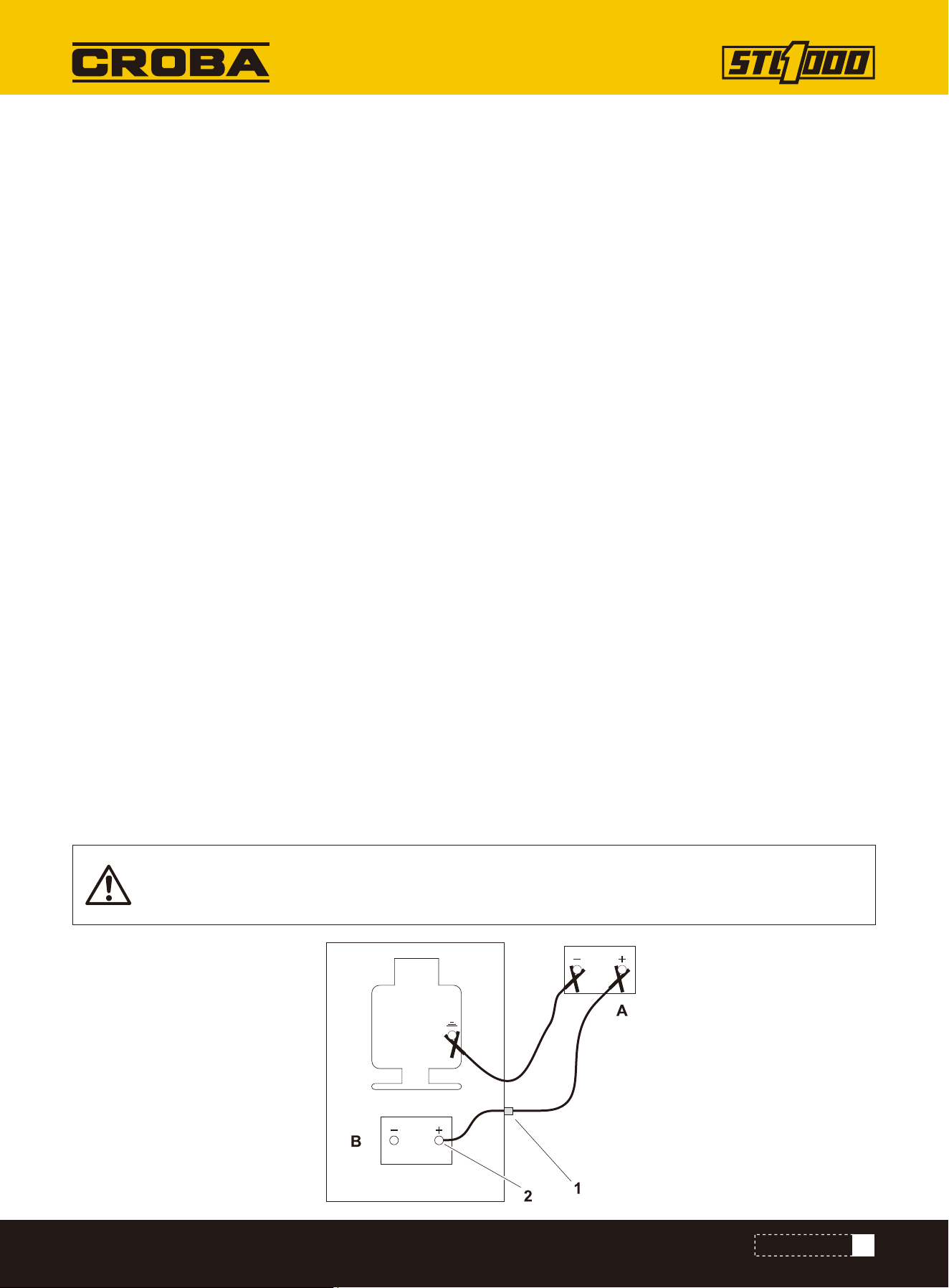
IMPORTANT: Some equipment may have a positive jumper cable terminal (1) located externally. If
so equipped, connect red positive (+) jumper cable clamp to terminal.
Check
1. Park service vehicle close to disabled equipment but do not allow vehicles to touch.
2. Set parking brake in both, if equipped.
3. Turn both off.
4. Disconnect machine controller, if equipped.
5. Inspect battery in disabled machine (B) for signs of cracking, bulging, leaking, or other damage.
6. Connect red positive (+) jumper cable clamp to positive (+) post of battery (2) in disabled machine.
Charge
To help avoid injury:
• Use a single 12V maximum source for charging. Never connect to rapid chargers or dual batteries.
• Never lean over battery when making connections.
• Never allow vehicles to touch when charging.
• Never short-circuit battery terminals for any reason or strike battery posts or cable terminals.
NOTICE:
• Electronic components can be easily damaged by electrical surges. Jump starting can damage electronics and
electrical systems, and is not recommended.
• Try to charge the battery instead. Use quality large diameter jumper cables capable of carrying high currents (400
amps or more). Low quality cables may not allow enough current flow to charge a dead/discharged battery.
40
MAINTENANCE
7. Connect the other red positive (+) jumper cable clamp to positive (+) post of battery in service vehicle (A).
8. Connect black negative (-) cable clamp to negative (-) post of battery in service vehicle.
9. Connect the other black negative (-) cable clamp to engine or frame ground on disabled machine, at least 12”
(305 mm) from failed battery, as shown.
10. Operate service vehicle engine at 1500-2000 rpm for a few minutes to build an electrical charge in failed battery.
11. Stop engine in service vehicle.
12. Remove jumper cables from service vehicle, black negative (-) clamp first. Do not allow clamps to touch.
13. Remove black negative (-) cable clamp from disabled engine or frame ground.
14. Remove red positive (+) cable clamp from disabledmachine.
15. Reconnect machine controller, if equipped.
16. Start disabled machine.
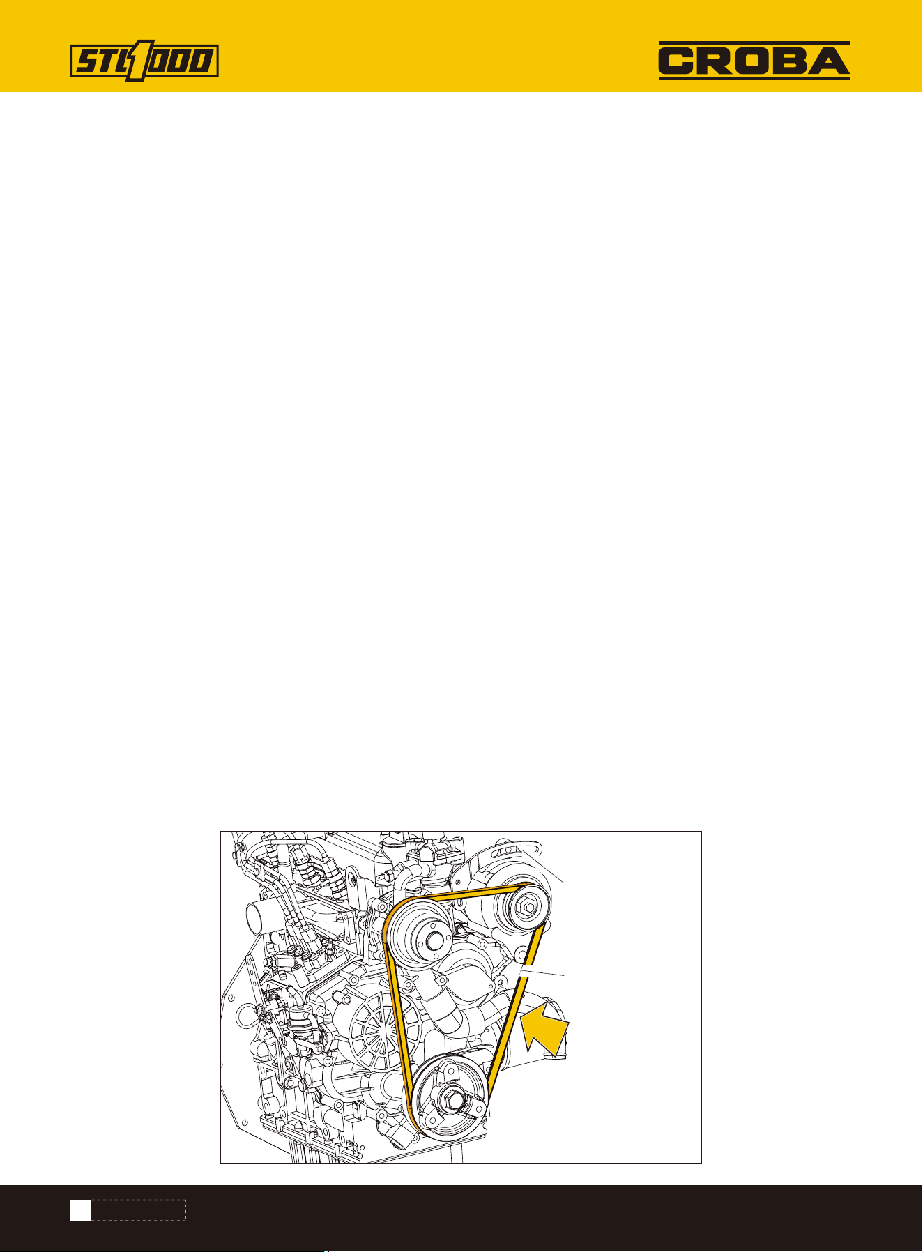
Check every 150 hours. Adjust tension as needed.
Change as needed.
Check for excessive slack, damage, or wear. Belt is properly tensioned when it moves about 1/4-3/8” (7-9mm)
when pushed at long span (shown).
BELT, FAN
Check
1.Loosen two alternator bolt (1, 2).
2.Adjust position as needed.
3.Tighten bolts.
4.Check tension.
Adjust Tension
1.Loosen two alternator bolts (1,2).
2.Replace fan belt.
3.Adjust position as needed.
4.Tighten bolts.
5.Check tension.
Change
1
2
41
MAINTENANCE
Check before startup and every 10 hours. Change every 1000 hours.
COOLANT
Add coolant
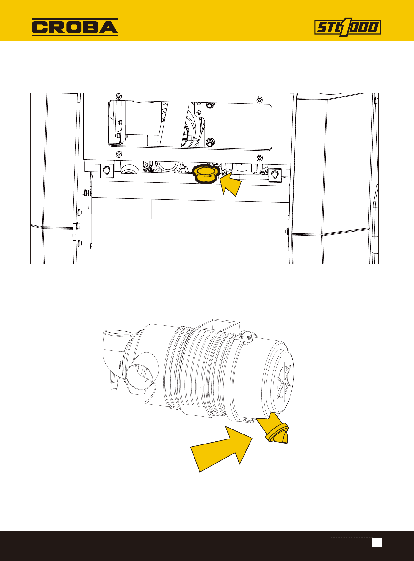
Check dust ejector valve (shown) before startup and every 10 hours. Ensure valve is not inverted, damaged, plugged,
or cracked.
Dust Ejector Valve
42
MAINTENANCE
Check for debris every 10 hours. Remove debris from engine compartment manually. Do not use water or compressed
air.
• Improperly installed primary element can lead to premature engine failure.
• Compressed air or water can damage filter elements.
• Tapping filter elements to loosen dirt can damage elements.
Check before startup and every 10 hours. Change when needed.
ENGINE COMPARTMENT
FILTER, AIR
1.Remove cover.
2.Remove primary element (3).
3.Wipe inside of housing (2) and cover.
4.Insert secondary element (4) and ensure it is seated
correctly.
5.Insert new primary element.
6.Install cover with dust ejector facing down.
7.Reset air filter service indicator.
Change
NOTICE: Only open air filter housing when red band on indicator is visible. Change the elements.
Do not attempt to clean them.
NOTICE: Check more often if operating in large brush, grassy conditions, or if machine is being
stored.
3
2
4

43
MAINTENANCE
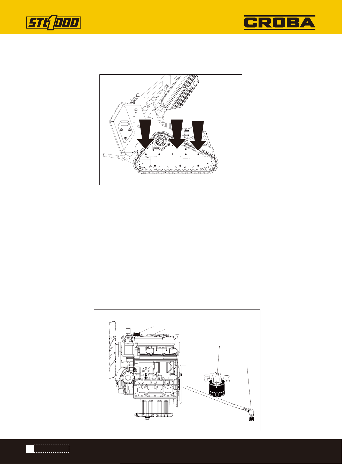
Change canister filter and inline filter every 600 hours. If refueling from cans, replace filters more often.
FILTER, FUEL
Change filter (shown) at 50 hours and every 300 hours thereafter.
FILTER, HYDRAULIC FLUID
44
MAINTENANCE
IMPORTANT: Ensure cylinders are fully retracted.
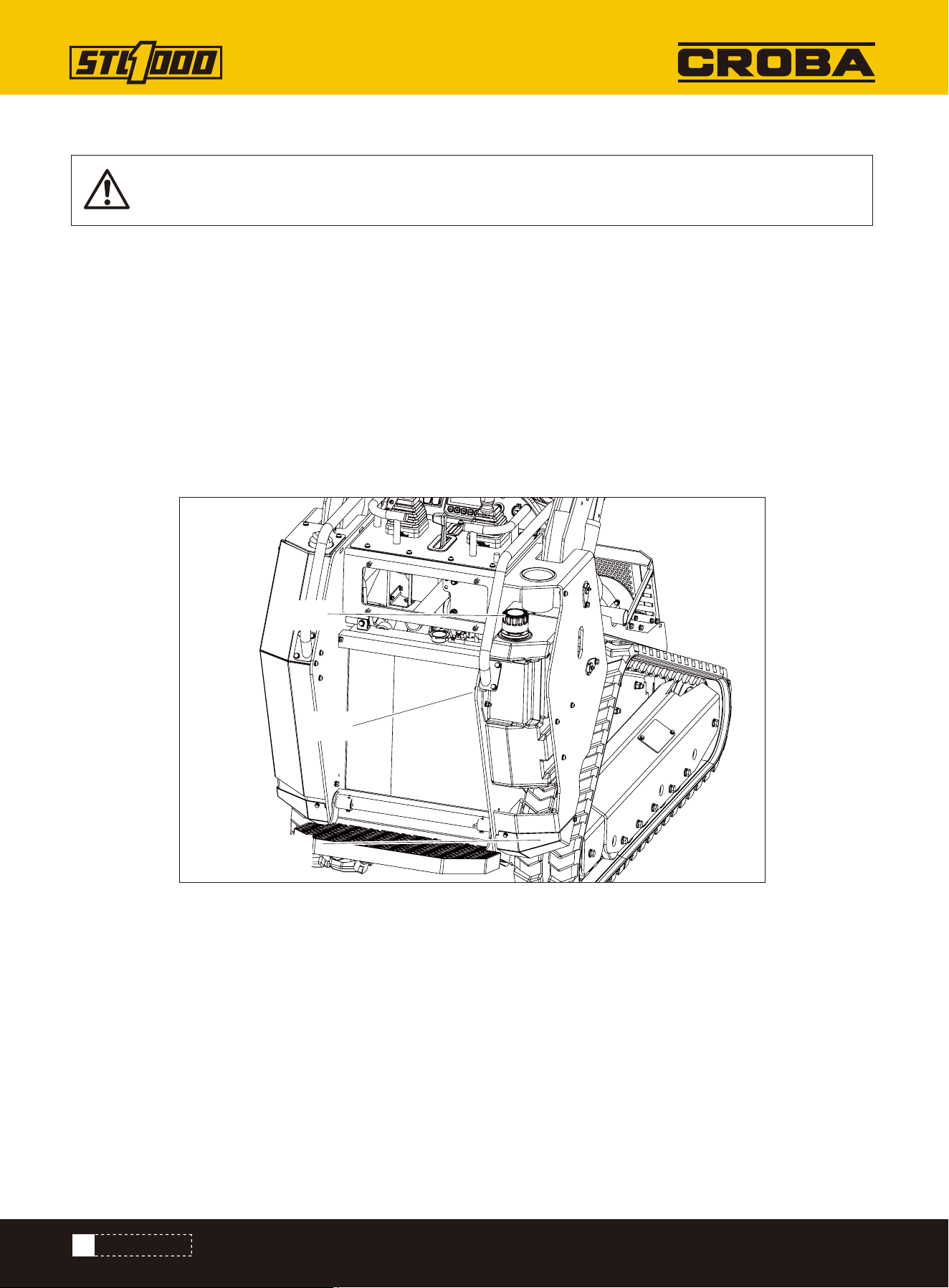
Check before startup and every 10 hours. Change every 600 hours.
1.Check level at sight glass (2).
2.Add THF at fill (1) as needed to keep level at halfway point on sight glass.
FLUID, HYDRAULIC
Check Level
1.Remove plug (3) to drain.
2.Install plug.
3.Add THF at fill to keep level at halfway point on sight glass.
Recommended use HM46 (#46 anti-wear hydraulic oil).
At 40 degrees Celsius, the viscosity is 46 centiss.
Change Fluid
NOTICE: Change every 250 hours if jobsite temperature exceeds 100° F(38° C) more than 50% of the
time.
3
1
2
45
MAINTENANCE
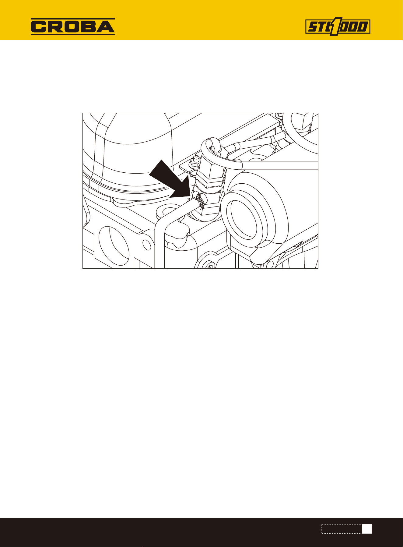
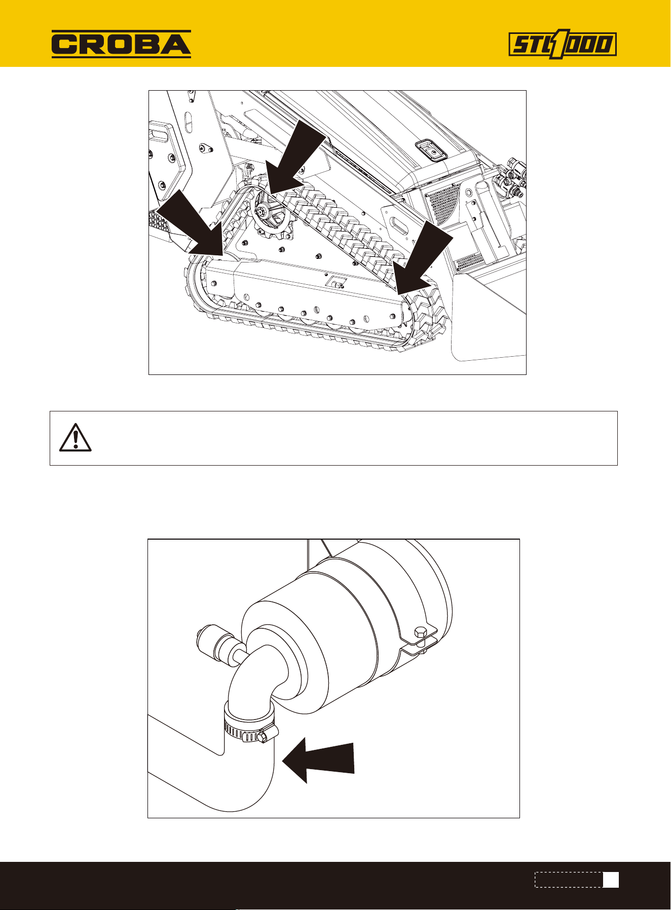
Check fuel hose (shown) and clamp bands every 50 hours.
If clamp is loose, apply oil to the threads and retighten.
If hose is worn, replace.
Bleed fuel system if hose and/or clamp is changed.
FUEL HOSE
46
MAINTENANCE
Pressurized fluid or air. Injection can cause death or serious injury. Refer to operator's manual for
correct use.
HYDRAULIC HOSES
To help avoid injury:
• Use a piece of cardboard or wood, rather than hands, to check for leaks.
• Before disconnecting a hydraulic line, turn engine off and operate all controls to relieve pressure.
• Lower, block, or support any raised component with a hoist.
• Cover connection with heavy cloth and loosen connector nut slightly to relieve residual pressure.
Catch all fluid in a container.
• Before using system, check that all connections are tight and all lines are undamaged.
• If you are injured, seek immediate medical attention from a doctor familiar with this type of injury.
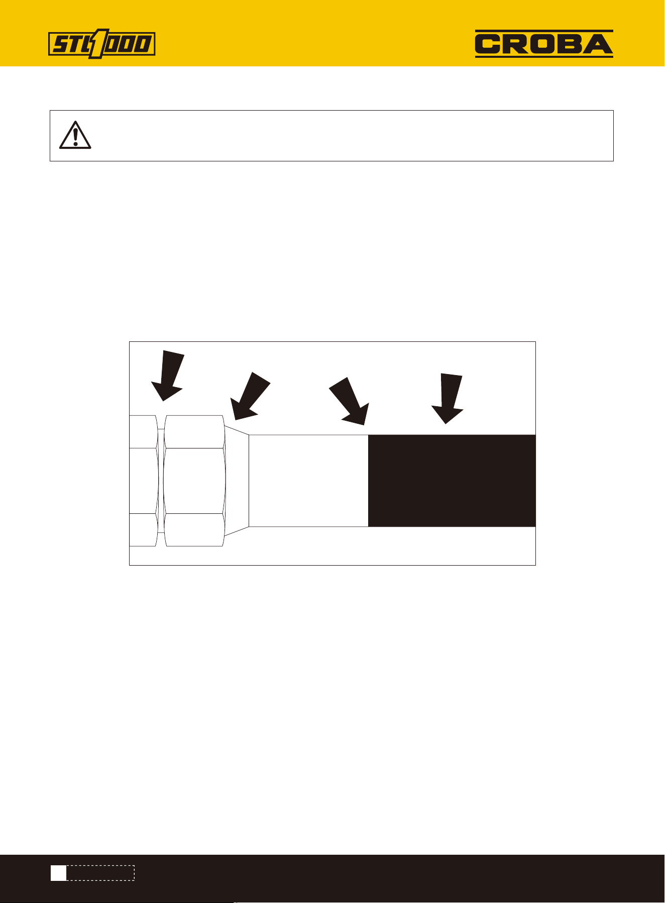
Check for leaks where shown before startup and every 10 hours of operation.
Check idler roller bearings (shown) at 50 hours and every 300 hours thereafter. Adjust as needed.
IDLER ROLLER BEARINGS
1.Lift machine.
2.Release track tension.
3.Check for movement of each hub when rocked back and forth. If hub has noticeable movement, adjust.
4.Adjust track tension.
Check
47
MAINTENANCE
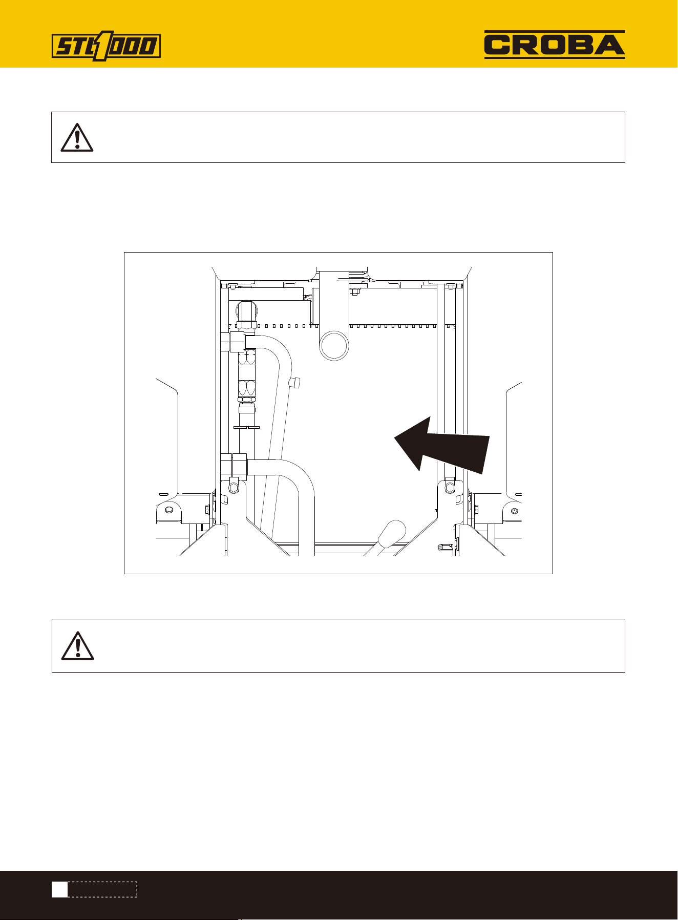
Check intake air line (shown) for dirt and debris every 300 hours.
If clamp is loose, apply oil to threads and retighten.
If hose is cracked or worn, replace.
INTAKE AIR LINE
NOTICE: Keep dust out of the intake air line to prevent damage to the engine.
48
MAINTENANCE
Check before startup and every 10 hours. Change at 50 hours and every 150 hours thereafter.
OIL, ENGINE
1. Check level at dipstick (3).
2. Add DEO at fill (4) as needed to keep level at highest
line on dipstick.
Check Level
1. While oil is warm, remove plug (1) to drain.
2. Install plug.
3. Remove filter (2) and replace with new filter.
4. Add DEO at fill to keep level at highest line on dip-
stick.
Change Oil and Filter
LUG NUTS
Check lug nuts (shown) at 10 hours, 50 hours, and every 300 hours thereafter. Tighten to 88-95ft·lb (108-129N·m)
as needed.
1
2
4
3
49
SAE 30
SAE 15W-40
SAE 10W-30
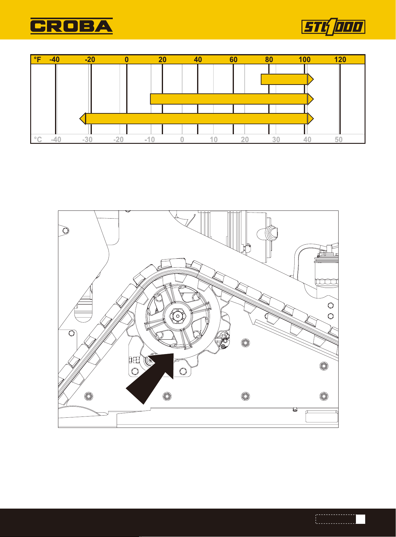
Check before startup and every 10 hours.
1. Start engine.
2. Ensure parking brake pin (shown) moves freely allowing brake to be set and released.
3. Clean mud and debris from area around pin.
PARKING BRAKE
MAINTENANCE
50
MAINTENANCE
1. Clean fins with compressed air or spray wash.
2. Open rear hood and spray through radiator toward engine.
3. If grease and oil are present on radiator, spray with solvent and allow to soak overnight.
Check every 50 hours. Clean as needed.
Check radiator (shown) for dirt, grass, and other debris.
Check radiator hoses for wear. Check hose clamps for proper tightness.
NOTICE: Radiator may need to be cleaned more frequently in dusty or grassy conditions.
NOTICE: Radiator may need to be cleaned more frequently in dusty or grassy conditions.
RADIATOR/HYDRAULIC FLUID COOLER
Check
Clean

51
MAINTENANCE
To help avoid injury:
• Service track grease cylinder only while standing away from zerk.
• Cover connection with heavy cloth when relieving pressure in cylinder.
• Check before startup and every 10 hours. Adjust as needed.
1. Lift track.
2. Remove gauge from stored location.
3. Thread gauge into connection.
4. Adjust tension.
• To tighten, pump MPG into grease zerk until gauge measures 700-900psi (48-62bar).
• To loosen, remove plug and drain all grease. Then follow tightening procedure.
5. Start engine.
6. Drive forward one machine length and check track tension.
Contents under pressure. Impact can cause death or serious injury. Relieve pressure before open-
ing.
Adjust
TRACK TENSION
52
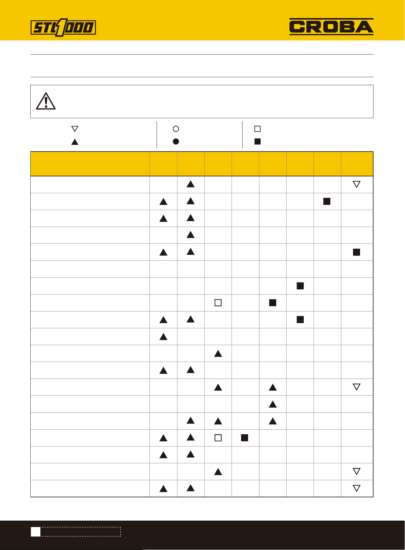
MAINTENANCE INTERVAL CHART
MAINTENANCE INTERVAL CHART
IMPORTANT: Chart indicates first instance of repeated maintenance procedures. See detailed
information below.
Battery
Coolant
Dust ejector valve
Engine compartment
Filter, air
Filter, engine oil (see Oil, engine)
Filter, fuel
Filter, hydraulic fluid
Fluid, hydraulic
Fuse box
Fuel hose
Hydraulic hoses
Idler roller bearings
Intake air line
Lug nuts
Oil, engine
Parking brake
Radiator/Hydraulic fluid cooler
Track tension
Adjust, service, or test
Check
Lube, initial
Lube
Change, initial
Change
Service
Start
up
10
Hours
50
Hours
150
Hours
300
Hours
600
Hours
1000
Hours
As
Needed

53
TROUBLE SHOOTING
TROUBLE SHOOTING
The starter does not crank.
The engine cranks but does
not start.
1. The electrical connections are cor-
roded or loose.
2. A fuse is blown or loose.
3. The battery is discharged.
4. The relay or switch is damaged.
5. A starter or starter solenoid is
damaged.
6. Internal engine components have
seized.
7. The safety interlock is engaged.
1. The starting procedure is incor-
rect.
2. The fuel tank is empty.
3. The fuel-shutoff valve is closed.
4. Dirt, water, stale fuel, or incorrect
fuel is in the fuel system.
5. The fuel line is clogged.
6. There is air in the fuel.
7. The glow plugs are inoperative.
8. The cranking speed is slow.
9. The air-cleaner filters are dirty.
10. The fuel filter is clogged.
11. The improper fuel grade for cold
weather is in the machine.
12. There is low compression.
13.The injection nozzles are dam-
aged.
14.The injection pump timing is
incorrect.
15. The injection pump is damaged.
16. The ETR solenoid is damaged.
1. Check the electrical connections
for good contact.
2. Correct or replace the fuse.
3. Charge the battery or replace it.
4. Contact your Authorized Service
Dealer.
5. Contact your Authorized Service
Dealer.
6. Contact your Authorized Service
Dealer.
7. Check the neutral setting on the
traction and auxiliary controls.
1. Refer to Starting the Engine.
2. Fill the tank with fresh fuel.
3. Open the fuel-shutoff valve.
4. Drain and flush the fuel system;
add fresh fuel.
5. Clean or replace the fuel line.
6. Bleed the nozzles and check for air
leaks at the fuel hose connections
and fittings between the fuel tank
and engine.
7. Check the fuse, glow plugs, and
wiring.
8. Check the battery, oil viscosity,
and starting motor (contact your
Authorized Service Dealer).
9. Service the air filters.
10. Replace the fuel filter
11. Drain the fuel system and
replace the fuel filter. Add fresh fuel
of proper grade for ambient tempera-
ture conditions. You may need to
warm the entire traction unit.
Problem Possible Cause Corrective Action

54
TROUBLE SHOOTING
The engine starts but does
not keep running.
The engine runs but knocks or
misses.
1. The fuel-tank vent is restricted.
2. Dirt or water is in the fuel system.
3. The fuel filter is clogged.
4. There is air in the fuel.
5. Improper fuel grade for cold
weather was used in the machine.
6. The spark-arrestor screen is
clogged.
7. The fuel pump is damaged.
1. Dirt, water, stale fuel, or incorrect
fuel is in the fuel system.
2. The engine is overheating.
3. There is air in the fuel.
4. The injection nozzles are damaged.
5. There is low compression
6. The injection-pump timing is incor-
rect.
7. There is excessive carbon buildup.
8. There is internal wear or damage.
1. Loosen the cap. If the engine runs
with the cap loosened, replace the
cap.
2. Drain and flush the fuel system;
add fresh fuel.
3. Replace the fuel filter.
4. Bleed the nozzles and check for
airleaks at fuel hose connections and
fittings between the fuel tank and
engine.
5. Drain the fuel system and replace
the fuel filter. Add fresh fuel of proper
grade for ambient temperature condi-
tions.
6. Clean or replace the spark-arrestor
screen.
7. Contact your Authorized Service
Dealer.
1. Drain and flush the fuel system;
add fresh fuel.
2. Refer to “The engine overheats.”
3. Bleed the nozzles and check for air
leaks at the fuel hose connections
and fittings between the fuel tank
and engine.
4. Contact your Authorized Service
Dealer.
The engine does not idle.
1. The fuel-tank vent is restricted.
2. Dirt, water, stale fuel, or incorrect
fuel is in the fuel system.
3. The air-cleaner filters are dirty.
4. The fuel filter is clogged.
5. There is air in the fuel.
6. The fuel pump is damaged.
7. There is low compression
1. Loosen the cap. If the engine runs
with the cap loosened, replace the
cap.
2. Drain and flush the fuel system;
add fresh fuel.
3. Service the air filters.
4. Replace the fuel filter.
5. Bleed the nozzles and check for air
leaks at fuel hose connections and
fittings between the fuel tank and
engine.
6. Contact your Authorized Service
Dealer.
Problem Possible Cause Corrective Action

55
TROUBLE SHOOTING
The engine overheats.
1. More coolant is needed.
2. There is restricted air flow to the
radiator.
3. The crankcase-oil level is incor-
rect.
4. The engine load is excessive.
5. Incorrect fuel is in the fuel
system.
6. The thermostat is damaged.
7. The fan belt is loose or broken.
8. Injection timing is incorrect.
9. The coolant pump is damaged.
10. The engine rpm is too low.
1. Check and add coolant.
2. Inspect and clean the radiator
screen with every use.
3. Fill or drain to the Full mark.
4. Reduce the load; use a lower
ground speed.
5. Drain and flush the fuel system;
add fresh fuel.
6. Contact your Authorized Service
Dealer.
7. Contact your Authorized Service
Dealer.
8. Contact your Authorized Service
Dealer.
9. Contact your Authorized Service
Dealer.
10.Check the high idle speed.
The engine loses power.
1. The engine load is excessive.
2. The crankcase-oil level is incor-
rect.
3. The air-cleaner filters are dirty.
4. Dirt, water, stale fuel, or incorrect
fuel is in the fuel system.
5. The engine is overheating.
6. The spark-arrestor screen is
clogged.
7. There is air in the fuel.
8. There is low compression.
9. The fuel-tank vent is restricted.
10. The injection-pump timing is
incorrect.
11. The injection pump is damaged.
12. The engine high idle speed is too
low.
1. Reduce the load; use a lower
ground speed.
2. Fill or drain to the Full mark.
3. Service the air filters.
4. Drain and flush the fuel system;
add fresh fuel.
5. Refer to "The engine overheats."
6. Clean or replace the spark-arrestor
screen.
7. Bleed the nozzles and check for air
leaks at fuel hose connections and
fittings between the fuel tank and
engine.
8. Contact your Authorized Service
Dealer.
Problem Possible Cause Corrective Action

56
TROUBLE SHOOTING
Exhaust produces excessive
black smoke.
Exhaust produces excessive
white smoke.
1. The engine load is excessive.
2. The air-cleaner filters are dirty.
3. Incorrect fuel is in the fuel
system.
4. The injection-pump timing is incor-
rect.
5. The injection pump is damaged.
6. The injection nozzles are dam-
aged.
1. The key was turned to the START
position before the glow-plug light
turned off.
2. The engine temperature is low.
3. The glow plugs are inoperative.
4. The injection-pump timing is incor-
rect.
5. The injection nozzles are dam-
aged.
6. There is low compression.
1. Reduce the load; use a lower
ground speed.
2. Service the air filters.
3. Drain and flush the fuel system;
add fresh fuel.
4. Contact your Authorized Service
Dealer.
5. Contact your Authorized Service
Dealer.
6. Contact your Authorized Service
Dealer.
1. Turn the key to the RUN position
and allow the glow-plug light to turn
off before starting the engine.
2. Check the thermostat.
3. Check the fuse, glow plugs, and
wiring.
4. Contact your Authorized Service
Dealer.
5. Contact your Authorized Service
Dealer.
6. Contact your Authorized Service
Dealer.
The machine does not drive.
1. The parking brake is engaged.
2. The hydraulic-fluid level is low.
3. The hydraulic system is damaged.
4. The tow valves are open.
5. The flow-divider valve lever is in 9
o'clock position.
6. A traction pump drive coupler is
loose or broken.
7. Pump and/or wheel motor is dam-
aged.
8. The control valve is damaged.
9. The relief valve is damaged.
1. Disengage the parking brake.
2. Add hydraulic fluid to the reservoir.
3. Contact your Authorized Service
Dealer.
4. Close the tow valves.
5. Move the lever to the 12 o'clock to
10 o'clock position.
6. Contact your Authorized Service
Dealer.
7. Contact your Authorized Service
Dealer.
8. Contact your Authorized Service
Dealer.
9. Contact your Authorized Service
Dealer.
Problem Possible Cause Corrective Action
57
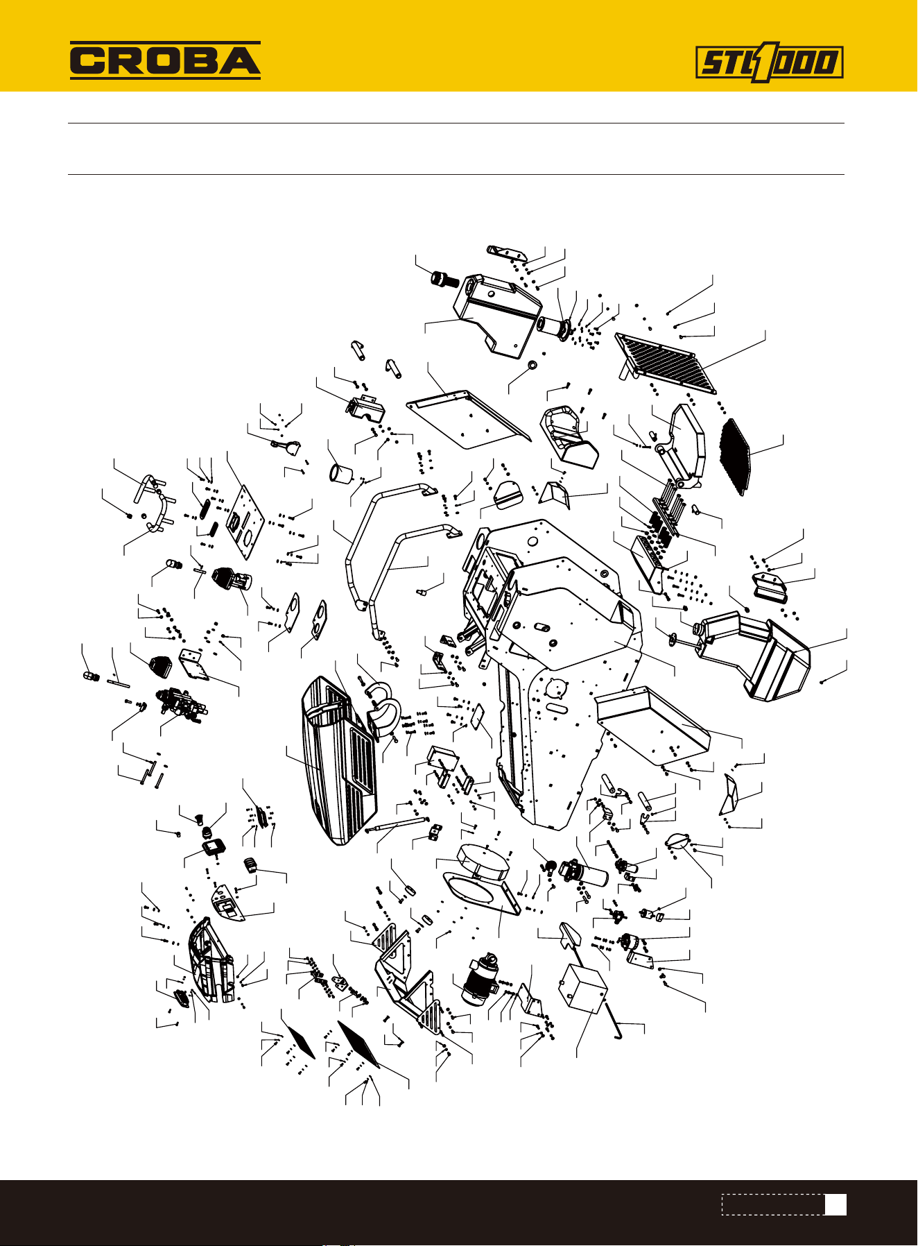
PARTS DIAGRAM
PARTS DIAGRAM
1
2
3
5
4
6
7
9
8
10
11
12
13
14
15
16
18
17
19
49
23
21
20
22
24
25
26
27
2928
30
31
32
43
33
34
35
36
37
38
39
40
41
42
44
45
46
47
48
50
52
53
74
57
73
54
55
56
94
58
59
60
61
62
63
64
65
66
67
68
69
70
71
72
75
76
77
79
78
80
81
82
83
84
86
85
87
88
89
90
91
92
93
95
96
98 99
101
124
98
102
106
99 98
121
98
109
108
107
109 108 107
118
108
107
131
129
128
132
119
98 99
118
125
110
115114
101
98
102
119
99
98
134
132
128
129
101
100
102
99
106
99
120
98
102
100
99
98
97
109
100
121
119
99
127
129
132
111
110
106
98
117107
101
100
52
102
98
119
99
120
98
100
98
99
103
?
104
123 105
130
116
101
98
100
99
112
106
109
133
101
121
109
109
101
106
132
129
121
9899
117
116
107
113
115
109 108
107
109
106109
116
106
101
100
101
122
98
98
126
121
109 108

58
PARTS LIST
PARTS LIST
NO. Description Qty.
1
2
3
4
5
6
7
8
9
10
11
12
13
14
15
16
17
18
19
20
21
22
23
24
25
26
27
28
29
Rack welding assembly
Shield welding 1 (Narrow type)
Shield welding 2 (Narrow type)
Pedal assembly
Pedal support welding (narrow type)
Pedal pin/shaft welding
Panel welding
Handrails welding - upper left
Handrails welding - upper right
Instrument panel plate
Lock catch welding
Engine cover
Air filter seat welding
Muffler seat welding
Ventilation shield welding
Connection plate
Handrails welding - right
Handrails welding - left
Fuel tank cover plate
Blocking plate
Blocking plate 2
Fuse box socket
Oil drain cap
Battery pressing plate
Curved hook screw
Limit pad
Nitrogen spring seat
Pin shaft fixing plate
Pin shaft
1
1
1
1
1
2
1
1
1
1
1
1
1
2
1
1
1
1
1
1
1
2
2
1
2
2
1
4
4
NO. Description Qty.
30
31
32
33
34
35
36
37
38
39
40
41
42
43
44
45
46
47
48
49
50
52
53
54
55
56
57
58
59
Oil-water separation support
Front ventilation cover
Lock seat
Ventilating board
Fuel tank fixing plate
Fan base plate
Front shield
Fuel filter bracket
Hood support bracket
Multitandem valve seat
Handlebar 1
Handlebar 2
Peddal rubber pad
Front ventilation cover 2
Hood connection plate
Spring pressing plate
Throttle seat
Side panel 1
Side panel 2
Fuel tank cover plate
Dashboard
Direct Injection Oil Cup
Oil-water separator
Electronic pump
Auxiliary water tank
25 Round pipe plug
Return oil filter
Battery
Throttle cable
1
1
1
2
2
1
1
1
1
1
1
1
1
1
1
1
1
1
1
1
1
4
1
1
1
4
1
1
1

59
PARTS LIST
NO. Description Qty.
60
61
62
63
64
65
66
67
68
69
70
71
72
73
74
75
76
77
78
79
80
81
82
83
84
85
86
87
88
89
90
Working light
Fuse box
Liquid level sensor
Water cup holder
USB Charger
Air filter
Hood lock
Waist cushion
Oil-absorbing flange
Fuel tank cap
Fuel tank
Hydraulic oil tank
Tower-shape cover
Fuel filter element
Rough filtration
Rubber strip hose clamp
Electric fan
Safe pulling rope
Tower-shape joint
Tower-shape joint
Multitandem valve
Pilot valve
Air fliter
Three-way switch
Display screen
Pilot handle
Multitandem valve handle
Nitrogen spring
Attachment rubber cover
Throttle rubber cover
Electric lock
1
1
1
1
1
1
1
1
1
1
1
1
1
1
1
1
1
1
1
1
1
1
1
1
1
1
1
1
1
1
1
NO. Description Qty.
91
92
93
94
95
96
97
98
99
100
101
102
103
104
105
106
107
108
109
110
111
112
113
114
115
116
117
118
119
120
121
Preheating indicator light
Oil leveler
Loudspeaker
Fuel tank oil plug
O-ring
Elastic cylindrical pin
Hexagon cylindrical head screw M8×25
Flat gasket 8
Elastic gasket 8
Hexagon head bolt M8x16
Hexagon head bolt M8x30
Non-metallic insert hexagonal lock thin nut M8
Hexagon head bolt M2x120
Non-metallic insert hexagonal lock thin nut M12
Spring
Hexagon head bolt M8x20
Flat gasket 6
Elastic gasket 6
Hexagon head bolt M6x12
Flat gasket 10
Hexagon head bolt - full thread - M10×20
Hexagon head bolt M8x70
Hexagon head bolt M10x30
Elastic gasket 10
Non-metallic insert hexagonal lock thin nut M10
Non-metallic insert hexagonal lock thin nut M5
Hexagon head bolt M6x20
Hexagon flat-round head screw M6×16
Hexagon flat-round head screw M8×20
Hexagon flat-round head screw M8×30
Hexagon head bolt M8x25
1
1
1
2
1
2
4
165
126
29
39
39
6
6
6
23
63
43
27
35
2
1
3
16
15
14
8
8
19
6
13

60
NO. Description Qty.
122
123
124
125
126
127
128
129
130
131
132
133
134
Hexagon head bolt M10×55
Flat gasket 12
Hexagon head bolt M8x35
Hexagon head bolt M10x90
Hexagon head bolt M6x25
Hexagon head bolt M5x12
Elastic gasket 5
Flat gasket 5
Hexagon head bolt M6x45
Hexagon cylindrical head screw M5×16
Non-metallic insert hexagonal lock thin nut M5
Hexagon head bolt M10×65
Hexagon head bolt M5×40
2
12
2
3
4
8
8
18
2
2
10
2
2
PARTS LIST
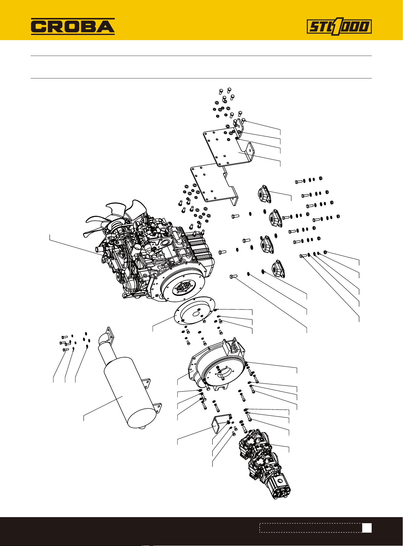
61
PARTS DIAGRAM (ENGINE EXPLOSIVE VIEW)
PARTS DIAGRAM (ENGINE EXPLOSIVE VIEW)
1
2
3
4
5
6
7
8 9
10
18
11
9
10
14 13 12
19 16
15 20
17 16
15
21 10
9
22
16
15
17 16
15
2410
99
23

62
PARTS LIST (ENGINE EXPLOSIVE VIEW)
PARTS LIST (ENGINE EXPLOSIVE VIEW)
NO. Description Qty.
1
2
3
4
5
6
7
8
9
10
11
12
13
14
15
16
17
18
19
20
21
22
23
24
Engine Frame
Solenoid valve bracket
Diesel Engine KUBOTA D1105
Shock-absorbing pad
Flywheel housing
Muffler
Coupler
Triple pump
Flat gasket 10
Elastic gasket 10
Hexagon head bolt fully threaded M10 x 1.25-25
Flat gasket 12
Elastic gasket 12
Hexagon head bolt M12×30
Flat gasket 8
Elastic gasket 8
Hexagon head bolt M8×16
Hexagon socket cylindrical head screw M10×30
Hexagon socket cylindrical head screw M8×30
Non-metallic insert hexagonal lock thin nut M8
Hexagon head bolt fully threaded M10 x 1.25-30
Hexagon head bolt M8×25
Hexagon head bolt M10×30
Non-metallic insert hexagonal lock thin nut M10
2
1
1
4
1
1
1
1
36
28
16
4
4
4
19
19
8
2
7
2
2
4
8
8
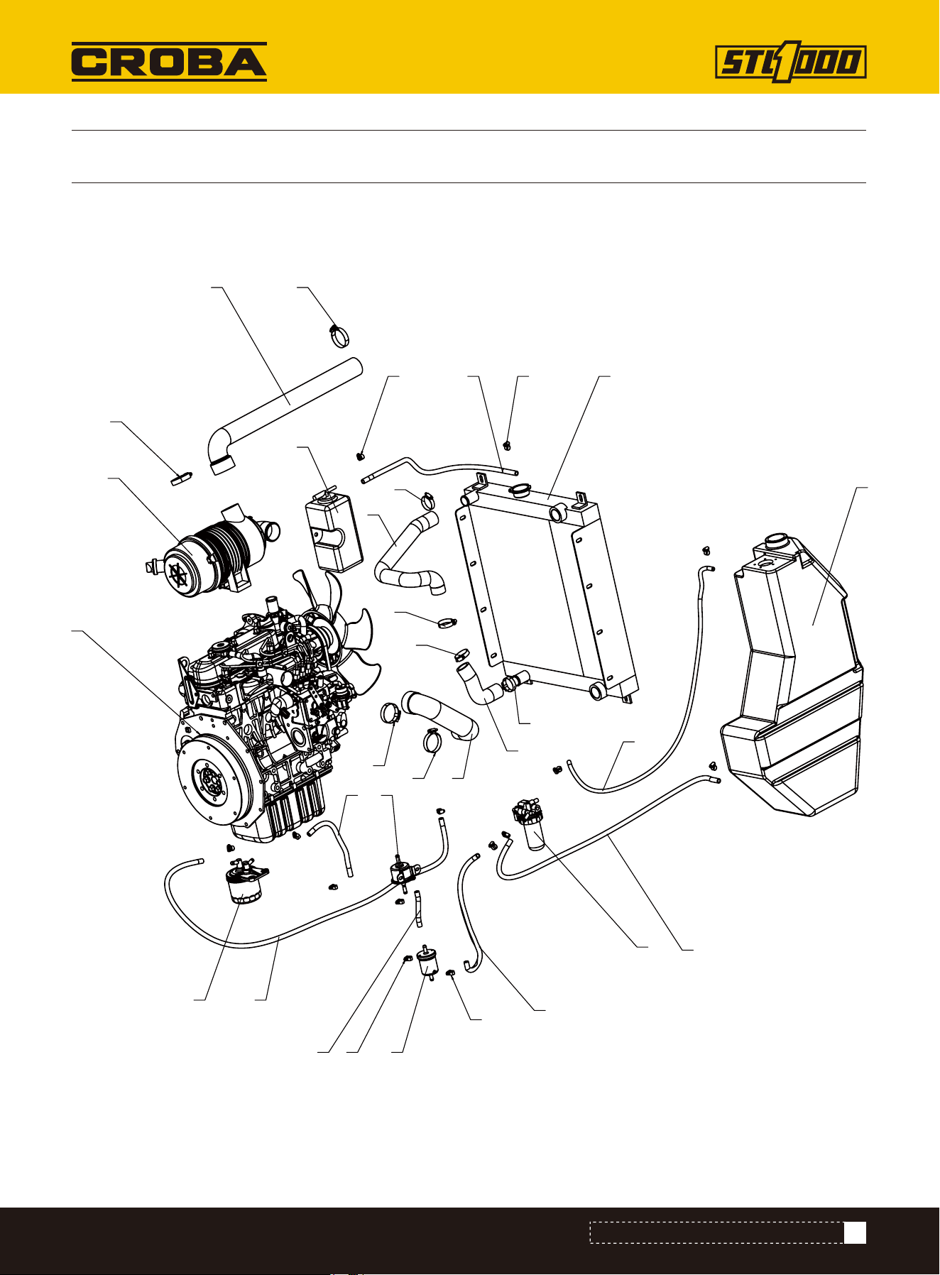
63
PARTS DIAGRAM (HOSE EXPLOSION DIAGRAM)
PARTS DIAGRAM (HOSE EXPLOSION DIAGRAM)
1
2
3
4
5
6
7
8
9
10
10
10
10
11
11
11
11
12 1313
14
15
13
16
13
17
18
19
20
21
22
23

64
Oil-water separator
Electronic pump
Auxiliary water tank
Fuel tank
Fuel filter element
Rough filter
Air filter
Engine
Radiator
Hose clamp
Hose clamp
Connection hose to auxiliary water tank
Hose clamp
Fuel hose
Fuel hose
Fuel hose
Fuel hose
Fuel hose
Fuel hose
Heat dissipation inlet pipe
Air inlet pipe 1
Air inlet pipe 2
Heat dissipation return pipe
PARTS LIST (HOSE EXPLOSION DIAGRAM)
PARTS LIST (HOSE EXPLOSION DIAGRAM)
NO. Description Qty.
1
2
3
4
5
6
7
8
9
10
11
12
13
14
15
16
17
18
19
20
21
22
23
1
1
1
1
1
1
1
1
1
4
4
1
14
1
1
1
1
1
1
1
1
1
1
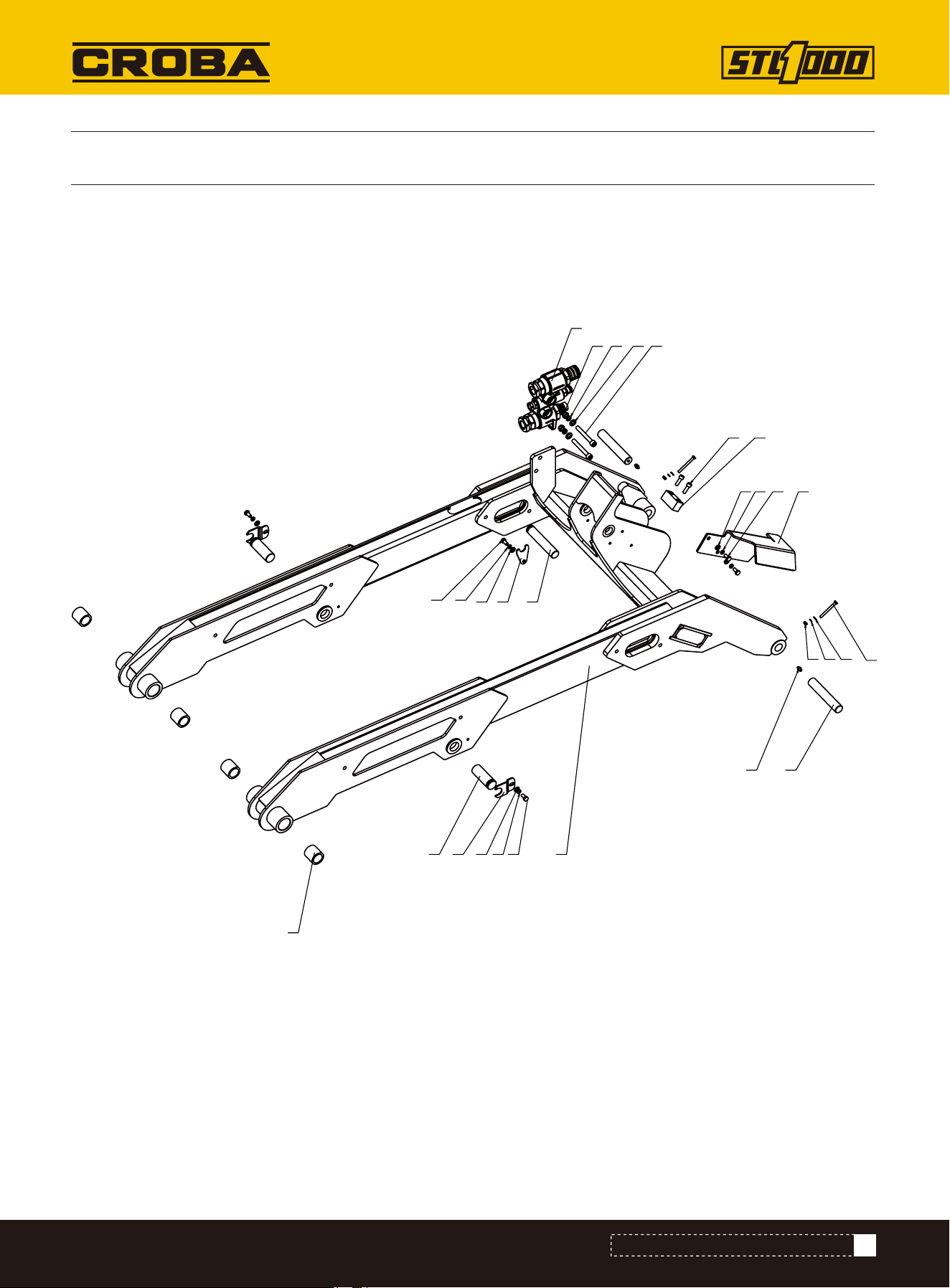
65
PARTS DIAGRAM (LIFTING ARM ASSEMBLY)
PARTS DIAGRAM (LIFTING ARM ASSEMBLY)
9
12
4
7
3
5
6
8
10
11
12 13 14
15
1617 18
19
20
2123 22
141312
12
1314

66
Lifting arm welding assembly
Pin shaft fixing plate
Pin shaft for arm cylinder
Bucket cylinder pin shaft
Bucket pin shaft
Cylinder guard plate
Pin shaft fixing plate 3
Bucket cylinder limit block
Copper bush
Quic-attach
Straight-through pressure injection oil cup HY8317.1 \ M8×1
Flat gasket 8
Elastic gasket 8
Hexagon head bolt M8×16
Flat gasket 10
Elastic gasket 10
Non-metallic insert hexagonal lock thin nut M10
Hex socket cylindrical head screw M10×80
Hex socket cylindrical head screw M8×25
Hexagon head bolt M6×60
Flat gasket 6
Elastic gasket 6
Non-metallic insert hexagonal lock thin nut M6
NO. Description Qty.
1
2
3
4
5
6
7
8
9
10
11
12
13
14
15
16
17
18
19
20
21
22
23
1
2
2
1
2
1
1
1
4
1
2
5
5
5
2
2
2
2
2
2
2
2
2
PARTS LIST (LIFTING ARM ASSEMBLY)
PARTS LIST (LIFTING ARM ASSEMBLY)
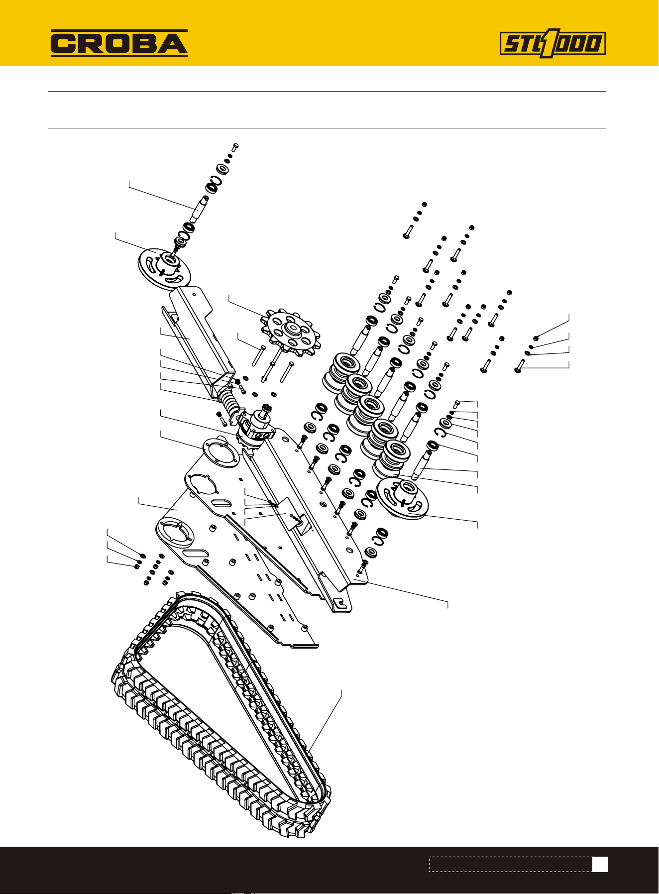
67
PARTS DIAGRAM (LEFT TRACK ASSEMBLY)
PARTS DIAGRAM (LEFT TRACK ASSEMBLY)
1
2
3
4
5
6
97
8
10
11 12
13 14 25
19 17 18
15
16
222120
23
24
17 19
26 27 28
29 19 17
24

68
Track support welding 2
Tensioning seat welding
Track side plate welding
Track roller
Block plate
Tension wheel shaft
Guiding wheel
Tension wheel
Track roller shaft
Driving wheel
Gasket plate
Tension oil cylinder
Deep groove ball bearing
Hole elastic retaining ring Type A 52
Rubber track
Motor
Elastic gasket 12
Hexagon head bolt M12×30
Flat gasket 12
Flat gasket 6
Elastic gasket 6
Hexagon head bolt M6×12
Hexagon head bolt M12×110
Non-metallic insert hexagonal lock thin nut M12
Oil seal
Hexagon socket cylindrical head screw M10×35
Elastic gasket 10
Flat gasket 10
Reinforced semi-round head square neck bolt M12×65
NO. Description Qty.
1
2
3
4
5
6
7
8
9
10
11
12
13
14
15
16
17
18
19
20
21
22
23
24
25
26
27
28
29
1
1
1
5
1
1
1
1
6
1
1
1
14
14
1
1
28
14
32
2
2
2
4
14
14
2
2
2
10
PARTS LIST (LEFT TRACK ASSEMBLY)
PARTS LIST (LEFT TRACK ASSEMBLY)
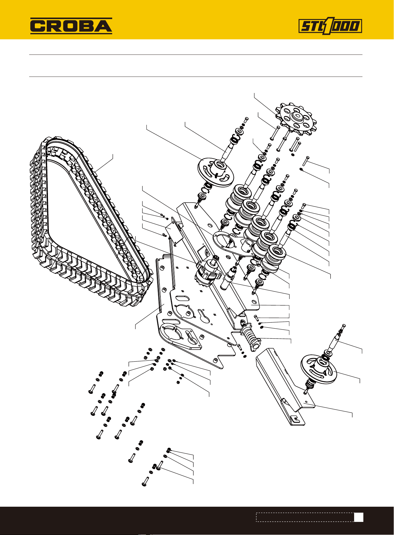
69
PARTS DIAGRAM (LEFT TRACK ASSEMBLY)
PARTS DIAGRAM (LEFT TRACK ASSEMBLY)
1
2
3
4
5
6
9
7
10
10
8
11
12
13 14
15
16
31
17
19
20 21 22
24
25
26
25
32
30 21 20
2728 29
33
26
25
18
30
34
20 21
23
20

70
Track support welding
Tensioning seat welding
Track side plate welding
Brake seat welding
Track roller
Block plate
Tension wheel shaft
Guiding wheel
Tension wheel
Track roller shaft
Driving wheel
Tension oil cylinder
Hexagon head bolt M10×30
Hexagonal nut M10
Deep groove ball bearing
Hole elastic retaining ring Type A 52
Motor
Rubber track
Brake cylinder
Flat gasket 12
Elastic gasket 12
Hexagon head bolt M12×30
Hexagon head bolt M12×110
Hexagon head bolt M10×70
Flat gasket 10
Elastic gasket 10
Hexagon head bolt M6×12
Elastic gasket 6
Flat gasket 6
NO. Description Qty.
1
2
3
4
5
6
7
8
9
10
11
12
13
14
15
16
17
18
19
20
21
22
23
24
25
26
27
28
29
1
1
1
1
5
1
1
1
1
6
1
1
1
1
14
14
1
1
1
32
28
14
4
2
6
4
2
2
2
PARTS LIST (LEFT TRACK ASSEMBLY)
PARTS LIST (LEFT TRACK ASSEMBLY)

71
Non-metallic insert hexagonal lock thin nut M12
Oil seal
Non-metallic insert hexagonal lock thin nut M10
Hexagon socket cylindrical head screw M10×35
Reinforced semi-round head square neck bolt M12×65
NO. Description Qty.
30
31
32
33
34
14
14
2
2
10
PARTS LIST (LEFT TRACK ASSEMBLY)
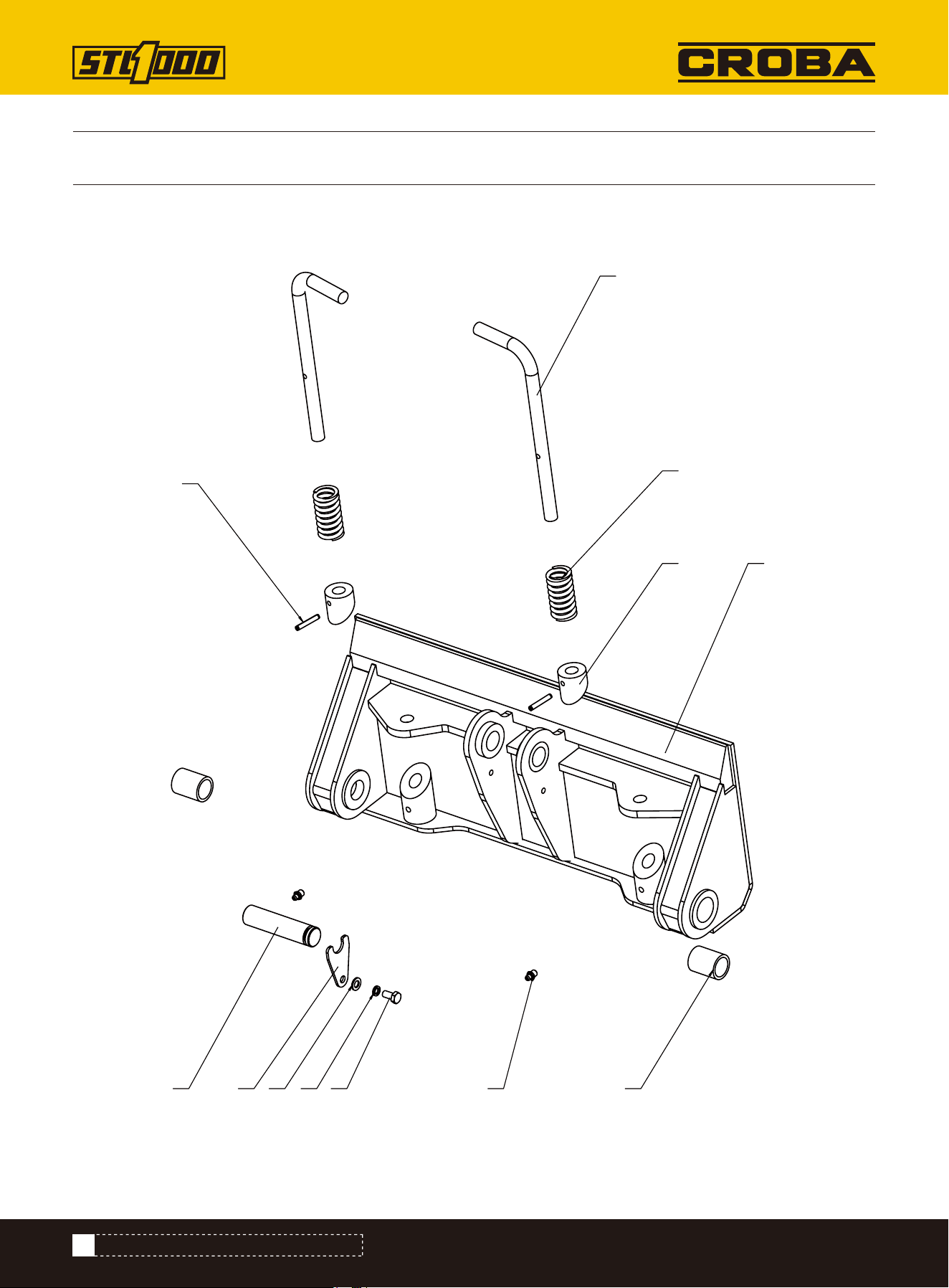
72
PARTS DIAGRAM (MOUNTING PLATE ASSEMBLY)
PARTS DIAGRAM (MOUNTING PLATE ASSEMBLY)
1
2
3
4 5
6
7
8
9
121110

73
Mounting plate welding frame
Handle
Teleflex
Pin shaft
Pin shaft fixing plate 3
Copper bush
Spring
HY8317.1 straight-through pressure injection oil cup
Elastic cylindrical pin (rolling/light) 6x35
Flat gasket 8
Elastic gasket 8
Hexagon head bolt M8×16
NO. Description Qty.
1
2
3
4
5
6
7
8
9
10
11
12
1
2
2
1
1
2
2
2
2
1
1
1
PARTS LIST (MOUNTING PLATE ASSEMBLY)
PARTS LIST (MOUNTING PLATE ASSEMBLY)
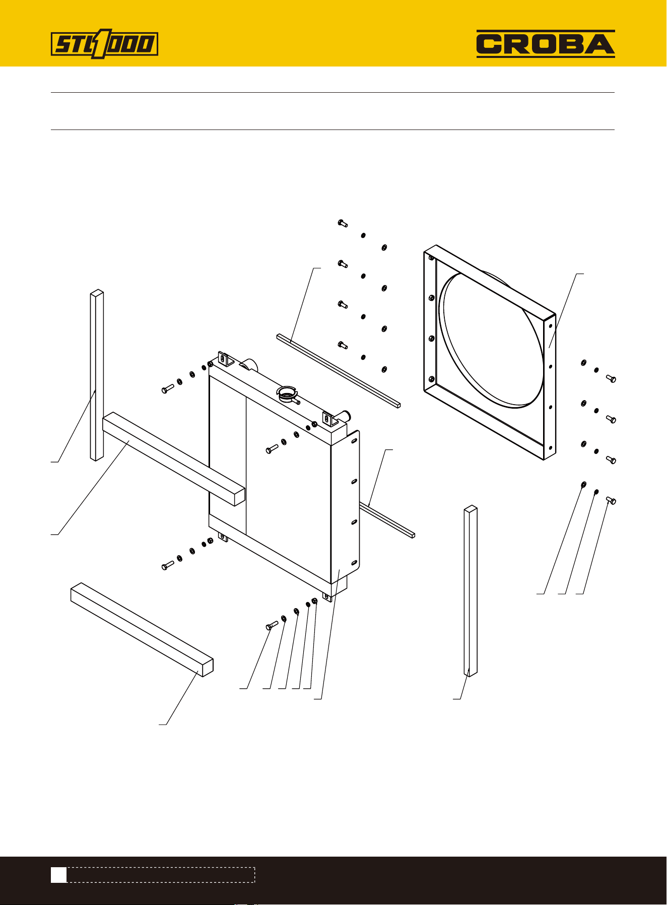
PARTS DIAGRAM (HEAT DISSIPATION ASSEMBLY)
74
1
2
876
5
5
4
4
3
3
9 6 6 7
10
PARTS DIAGRAM (HEAT DISSIPATION ASSEMBLY)

PARTS LIST (HEAT DISSIPATION ASSEMBLY)
PARTS LIST (HEAT DISSIPATION ASSEMBLY)
NO. Description Qty.
1
2
3
4
5
6
7
8
9
10
Air deflector welding assembly
Radiator
Sealing strips
Sealing strips
Sealing strips
Flat gasket 8
Elastic gasket 8
Hexagon head bolt M8×20
Hexagon head bolt M8×30
Non-metallic insert hexagonal lock thin nut M8
1
1
2
2
2
16
12
8
4
4
75