
Operator’s Manual
www.mechmaxx.com
WARRANTY


TABLE OF CONTENTS
TABLE OF CONTENTS
SPECIFICATIONS
1
BEFORE EVERY USE
12
EVERY WEEK
12
AFTER EVERY SEASON
12
TREE PUSHER
11
LOG DOGS
11
RECEIVER HITCH
11
HYDRAULIC SYSTEM
12
BOLT TORQUE
12
ENGLISH TORQUE SPECIFICATIONS
12
METRIC TORQUE SPECIFICATIONS
13
2
12
SAFETY SIGNS
IMPORTANT SAFETY INFORMATION
YOUR SAFETY
GENERAL SAFETY
EQUIPMENT SAFETY GUIDELINES
4
4
4
SAFETY TRAINING
5
SAFETY SIGNS
5
PREPARATION
5
MAINTENANCE SAFETY
6
HYDRAULIC SAFETY
6
TRANSPORT SAFETY
7
TO THE NEW OPERATOR OR OWNER
7
MACHINE COMPONENTS
8
HOOK-UP TORO MOUNT HITCH
8
UNHOOK TORO MOUNT HITCH
8
HYDRAULIC CONNECTIONS & MOUNTING
9
MACHINE OPERATOR AWARENESS
9
VOLT WIRE DIAGRAM FOR HYDRAULIC DIVERTER
10
3
4
8
OPERATION
MAINTENANCE
11
EQUIPMENT FEATURE WARNINGS
13
SPECIFICATION
14
PARTS DIAGRAM
15-16
PARTS LIST
1
www.mechmaxx.com
TABLE OF CONTENTS

SPECIFICATIONS
2
www.mechmaxx.com
SPECIFICATIONS
Lift Capacity
Grapple Opening
Hydraulic Cylinder
Rotator Power Capacity
Rotational Ability
Flow Range Low
Flow Range High
Hydraulic Pressure
Maximum Static Axial Load
Package Method
Finish
Warranty
Packing Size
Weight (N.W./G.W.)
1500 Ibs
59 in
2 in
1.5 tons
360° One Direction Rotation
8 gal/min
12 gal/min
2900 psi
30 kN
Iron Fram with film
Durable Powder Coated finish
1year
43x35x35 in
266/456 Ibs
Model RLG61

3
www.mechmaxx.com
SAFETY
SAFETY SIGNS
The rating plate on your machine may show symbols. These represent important information about the product or instruc-
tions on its use.

4
www.mechmaxx.com
YOUR SAFETY
IMPORTANT SAFETY INFORMATION
SAFETY
YOU are responsible for the SAFE operation and mainte-
nance of your MECHMAXX Mini Skid Steer Rotating Mini
Grapple. YOU must ensure that you and anyone else who
is going to use, maintain or work around the Mini Skid
Steer Rotating Mini Grapple be familiar with the using and
maintenance procedures and related SAFETY information
contained in this manual. This manual will take you
step-by-step through your working day and alerts you to
all good safety practices that should be used while using
the Mini Skid Steer Rotating Mini Grapple.
Remember, YOU are the key to safety. Good safety
practices not only protect you but also the people around
you. Make these practices a working part of your safety
program. Be certain that EVERYONE using this equipment
is familiar with the recommended using and maintenance
procedures and follows all the safety precautions. Most
accidents can be prevented. Do not risk injury or death by
ignoring good safety practices.
1.Mini Skid Steer Rotating Mini Grapple owners must give
operating instructions to operators or employees before
allowing them to operate the machine, and at least annu-
ally thereafter.
2.The most important safety device on this equipment is
a SAFE operator. It is the operator’s responsibility to read
and understand ALL Safety and Operating instructions in
the manual and to follow these. Most accidents can be
avoided.
3.A person who has not read and understood all using and
safety instructions is not qualified to use the machine. An
untrained operator exposes himself and bystanders to
possible serious injury or death.
4.Do not modify the equipment in any way. Unauthorized
modification may impair the function and/or safety and
could affect the life of the equipment.
5.Think SAFETY! Work SAFELY!
1. Read and understand the Operator’s Manual and all
safety signs before using, maintaining, adjusting, or
cleaning the Mini Skid Steer Rotating Mini Grapple.
2. Have a first-aid kit available for use should the need
arise and know how to use it.
3. Have a fire extinguisher available for use should the
need arise and know how to use it.
4. Do not allow riders.
5. Wear appropriate protective gear. This list includes but
is not limited to:
- A hard hat
- Protective shoes with slip resistant soles
- Heavy gloves
- Heavy gloves
- Wet weather gear
- Hearing Protection
6. Install and secure all guards before starting.
7. Wear suitable ear protection for prolonged exposure to
excessive noise.
8. Turn machine off, stop and disable engine, remove
ignition key and place in your pocket, set park brake and
wait for all moving parts to stop before servicing, adjust-
ing, repairing, or unplugging.
9. Clear the area of people, especially small children,
before using the unit.
10. Review safety related items annually with all person-
nel who will operating or maintaining the Mini Skid Steer
Rotating Mini Grapple.
1. Safety of the operator and bystanders is one of the
main concerns in designing and developing equipment.
However, every year many accidents occur which could
have been avoided by a few seconds of thought and a
more careful approach to handling equipment. You, the
operator, can avoid many accidents by observing the
following precautions in this section. To avoid personal
injury or death, study the following precautions and insist
those working with you, or for you to follow them.
2. In order to provide a better view, certain photographs or
illustrations in this manual may show an assembly with a
safety shield removed. However, equipment should never
be used in this condition. Keep all shields in place. If
shield removal becomes necessary for repairs, replace
the shield prior to use.
GENERAL SAFETY
EQUIPMENT SAFETY GUIDELINES

5
www.mechmaxx.com
SAFETY
3.Replace any safety sign or instruction sign that is not
readable or is missing. Location of such safety signs is
indicated in this manual.
4.Never use alcoholic beverages or drugs which can
hinder alertness or coordination while using this equip-
ment. Consult your doctor about using this machine while
taking prescription medications.
5.Under no circumstances should young children be
allowed to work with this equipment. Do not allow
persons to use or assemble this unit until they have read
this manual and have developed a thorough understanding
of the safety precautions and of how it works. Review the
safety instructions with all users annually.
6.This equipment is dangerous to children and persons
unfamiliar with its operation. The operator should be a
responsible, properly trained and physically able person
familiar with machinery and trained in this equipment's
operations. If the elderly are assisting with work, their
physical limitations need to be recognized and accommo-
dated.
7.Never exceed the limits of a piece of machinery.
If its ability to do a job, or to do so safely, is in question -
DON'T TRY IT.
8.Do not modify the equipment in any way. Unauthorized
modification may result in serious injury or death and may
impair the function and life of the equipment.
9.In addition to the design and configuration of this imple-
ment, including Safety Signs and Safety Equipment,
hazard control and accident prevention are dependent
upon the awareness, concern, prudence, and proper train-
ing of personnel involved in the operation, transport, main-
tenance, and storage of the machine. Refer also to Safety
Messages and operation instruction in each of the appro-
priate sections of the Mini Skid Steer and machine manu-
als. Pay close attention to the Safety Signs affixed to the
Mini Skid Steer and the machine.
1.Safety is a primary concern in the design and manufac-
ture of our products. Unfortunately, our efforts to provide
safe equipment can be wiped out by a single careless act
of an operator or bystander.
2.In addition to the design and configuration of equip-
ment, hazard control and accident prevention are depen-
dent upon the awareness, concern, prudence, and proper
training of personnel involved in the operation, transport,
maintenance, and storage of this equipment.
3.It has been said, "The best safety feature is an
informed, careful operator." We ask you to be that kind of
an operator. It is the operator's responsibility to read and
understand ALL Safety and Using instructions in the
manual and to follow these. Accidents can be avoided.
4.the machine. If this machine is used by any person other
than yourself, or is loaned or rented, it is the machine
owner's responsibility to make certain that the operator,
prior to using:
a.Reads and understands the operator's manuals.
b.Is instructed in safe and proper use.
5.Know your controls and how to stop the Mini Skid Steer
and machine quickly in an emergency. Read this manual
and the one provided with Mini Skid Steer.
6.Train all new personnel and review instructions
frequently with existing workers. Be certain only a proper-
ly trained and physically able person will use the machin-
ery. A person who has not read and understood all using
and safety instructions is not qualified to use the
machine. An untrained operator exposes himself and
bystanders to possible serious injury or death. If the elder-
ly is assisting with the work, their physical limitations
need to be recognized and accommodated.
1.Always keep safety signs clean and legible.
2.Replace safety signs that are missing or have become
illegible.
3.Replaced parts that displayed a safety sign should also
display the current sign.
4.Safety signs have a part number in the lower righthand
corner. Use this part number when ordering replacement
parts.
5.Safety signs are available from your authorized Distribu-
tor or Dealer Parts Department or the factory.
1.Never use the machine until you have read and
completely understand this manual, the Mini Skid Steer
Operator's Manual and each of the Safety Messages found
on the safety signs on the Mini Skid Steer and machine.
2.Personal protection equipment including hard hat,
safety glasses, safety shoes, and gloves are recommend-
ed during assembly, installation, operation, adjustment,
maintaining, repairing, removal, cleaning, or moving the
unit. Do not allow long hair, loose fitting clothing or jewel-
ry to be around equipment.
SAFETY TRAINING
SAFETY SIGNS
PREPARATION

6
www.mechmaxx.com
SAFETY
3.PROLONGED EXPOSURE TO LOUD NOISE MAY CAUSE
PERMANENT HEARING LOSS!
Power equipment with or without equipment attached
can often be noisy enough to cause permanent, partial
hearing loss. We recommend that you wear hearing
protection on a full-time basis if the noise in the Opera-
tor's position exceeds 80db. Noise over 85db on a
long-term basis can cause severe hearing loss. Noise over
90db adjacent to the Operator over a long-term basis may
cause permanent, total hearing loss. NOTE: Hearing loss
from loud noise (from Mini Skid Steer, chain saws, radios,
and other such sources close to the ear) is cumulative
over a lifetime without hope of natural recovery.
4.Clear working area of stones, branches or hidden obsta-
cles that might be hooked or snagged, causing injury or
damage.
5.Use only in daylight or good artificial light.
6.Be sure machine is properly mounted, adjusted and in
good operating condition.
7.Ensure that all safety shielding, and safety signs are
properly installed and in good condition.
1.Good maintenance is your responsibility. Poor mainte-
nance is an invitation to trouble.
2.Follow good shop practices.
- Keep service area clean and dry.
- Be sure electrical outlets and tools are properly ground-
ed.
- Use adequate light for the job at hand.
3.Make sure there is plenty of ventilation. Never operate
the engine of the towing vehicle in a closed building. The
exhaust fumes may cause asphyxiation.
4.Before working on this machine, shut off the engine, set
the brake, and turn fuel valve off.
5.Never work under equipment unless itis blocked secure-
ly.
6.Always use personal protection devices such as eye,
hand and hearing protectors, when performing any service
or maintenance work. Use heavy or leather gloves when
handling blades.
7.Where replacement parts are necessary for periodic
maintenance and servicing, genuine factory replacement
parts must be used to restore your equipment to original
specifications. The manufacturer will not be responsible
for injuries or damages caused by use of unapproved parts
and/or accessories.
8.A fire extinguisher and first aid kit should be kept readily
accessible while performing maintenance on this equip-
ment.
9.Periodically tighten all bolts, nuts and screws and
check that all electrical and fuel connections are properly
secured to ensure unit is in a safe condition.
10.When completing a maintenance or service function,
make sure all safety shields and devices are installed
before placing unit in service.
1.Make sure that all the components in the hydraulic
system are kept in good condition and are clean.
2.Before applying pressure to the system, make sure all
components are tight, and that lines, hoses and couplings
are not damaged.
3.Do not attempt any makeshift repairs to the hydraulic
lines, fittings, or hoses by using tapes, clamps or
cements. The hydraulic system operates under extremely
high pressure. Such repairs will fail suddenly and create a
hazardous and unsafe condition.
4.Wear proper hand and eye protection when searching for
a high-pressure hydraulic leak. Use a piece of wood or
cardboard as a backstop instead of hands to isolate and
identify a leak.
5.If injured by a concentrated high-pressure stream of
hydraulic fluid, seek medical attention immediately.
Serious infection or toxic reaction can develop from
hydraulic fluid piercing the skin surface.
6.Relieve pressure on hydraulic system before maintain-
ing or working on system.
MAINTENANCE SAFETY
HYDRAULIC SAFETY

7
www.mechmaxx.com
1.Comply with state and local laws governing safety and
transporting of machinery on public roads.
2.Check that all the lights, reflectors and other lighting
requirements are installed and in good working condition.
3.Do not exceed a safe travel speed. Slow down for rough
terrain and cornering.
4.Do not drink and drive.
5.Be a safe and courteous driver. Always yield to oncom-
ing traffic in all situations, including narrow bridges, inter-
sections, etc. Watch for traffic when operating near or
crossing roadways.
Follow all safety instructions exactly. Safety is every-
one's business. By following recommended procedures, a
safe working environment is provided for the operator,
bystanders, and the area around the worksite. Untrained
operators are not qualified to operate the machine.
Many features incorporated into this machine are the
result of suggestions made by customers like you. Read
this manual carefully to learn how to use the chipper
safely and how to set it to provide maximum field efficien-
cy. By following the using instructions in conjunction with
a good maintenance program, your Mini Skid Steer Rotat-
ing Mini Grapple will provide many years of trouble- free
service.
TRANSPORT SAFETY
TO THE NEW OPERATOR OR OWNER
SAFETY
8
www.mechmaxx.com
OPERATION
OPERATION
When attaching the Rotating Mini Grapple to a Mini Skid
Steer, follow this procedure:
1.Make sure that all bystanders, especially small children
are clear of the work area.
2.Make sure there is enough room and clearance to safely
drive up to the Rotating Mini Grapple.
3.Drive up to The Rotating Mini Grapple while aligning the
mounting components, and hook up into the mount.
The Mini Steer Skid Bucket utilizes a Toro mount receiver
plate for easy connection and disconnection.
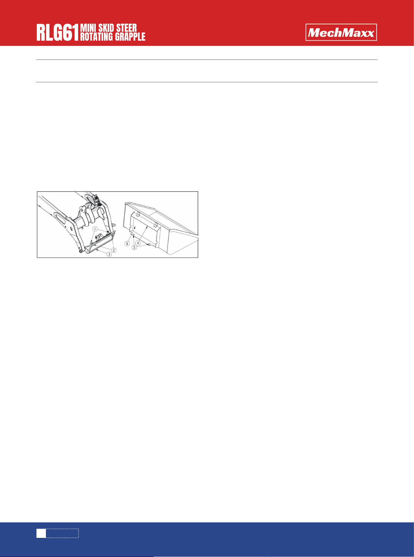
1. Check loader and bucket hitch plates before hook-
ing-up the bucket. Make sure all components are in good
working condition before putting them into service:
Check for and remove any debris in the loader and bucket
hitch plates.
Check for structural cracks in the hitch plates. Repair or
replace hitch plates as needed.
Check hitch components frequently. Repair or replace any
part that is excessively worn, bent, broken, or missing.
Lubricate lock pins (#1) at the prescribed interval in your
compact loader manual.
Check operation of lock pins (#1). Lock pins must move
freely and extend fully into the hitch plate bottom slots
(#5).
2. Raise lock pins (#1) by rotating the handles 180°
until they point out as shown.
3. Use anti-slip steps/surfaces and grab handles on the
compact loader when stepping on and off the unit.
4. Start compact loader.
5. Drive slowly to the bucket while making sure the
loader’s hitch plate top (#2) is parallel with the bucket’s
top angle bar (#4).
6. Tilt top of loader hitch plate (#2) slightly forward.
7. Place top of loader’s hitch plate (#2) under the buck-
et’s top angled bar (#4) and slowly raise loader hitch
plate (#3) up until the loader hitch plate is seated under
the top angle bar.
8. Tilt top of loader hitch plate (#2) back until the bucket
hitch plate (#6) makes full contact with the face of
loader hitch plate (#3) and the bucket’s hitch plate (#6)
is slightly off the ground.
9. Shut compact loader down before dismounting.
10. Lower lock pins (#1) by rotating the handles 180°
until they point in. If needed tap on lock pins to drive them
down and through bottom slots (#5).
11. Check hitch hook-up to verify it is locked properly.
a.Make sure top of loader hitch plate (#2) is fully seated
under the bucket’s top angle bar (#4).
b.Make sure bottom of loader hitch plate (#3) is seated
against bucket’s hitch plate (#6)
c.Make sure lock pins (#1) are fully inserted through
bottom slots (#5) and are fully down.
1. Park on a flat, level, solid surface.
2. Lower bucket until it is slightly above the surface and
angled so that the front of the bucket is slightly higher
than the back.
3. Without changing the height of the loader arms and
attachment, shut compact loader down. Unhook bucket
as follows:
a.Rotate the hitch latch pins (#1) to the unlocked
position by turning them so that the handles are pointing
outward. Make sure the hitch latch pins are pulled up all
the way to ensure a proper disconnect.
b.Return to compact loader and tilt top of hitch plate (#3)
slightly forward toward the bucket.
c.Slowly lower bucket until its top angle bar (#4) and
loader hitch (#3) have separated.
d.Back compact loader slowly away from the bucket while
making sure the Toro mount hitch does not interfere with
the bucket.
MACHINE COMPONENTS
HOOK-UP TORO MOUNT HITCH
UNHOOK TORO MOUNT HITCH

9
www.mechmaxx.com
OPERATION
MACHINE OPERATOR AWARENESS
Engage the lock pins to secure The Rotating Mini Grapple
to the loader.
Connect the hydraulics:
Use a clean rag or paper towel to clean the dirt from the
couplers on the hose ends of the Mini Skid Steer.
Connect the hoses to the Mini Skid Steer couplers. Be
sure the couplers are securely seated.
Route and secure the hoses along the frame with clips,
tape or plastic ties to prevent binding and pinching. Be
sure to provide slack for tilting.
Raise The Rotating Mini Grapple.
Check that all hydraulic connections and locks are secure
before beginning work.
Do not operate this machine until you have read the
manual page by page and under-stand the manual. The
owner of this machine is responsible for all operators and
sup-port personnel in the operation and safety precau-
tions of this equipment. Proper training prior to operation
of the equipment is obligatory.
• Study the manual and read all safety instructions
carefully, including all instruction stickers on the
machine.
• Before anyone uses the attachment, make sure that
he/she also studies these instructions for use and all
safety regulations
• The operator must be of age (not a minor) and in good
health.
• The operator cannot be under the influence of alcohol,
drugs or medicines.
• Stay alert! Do not operate the attachment when
fatigued.
• In order not to endanger the safety of the operator, do
not modify the attachment.
• Use only original parts replacements. Remove all
inappropriate components that don’t belong to the
attachment.
• Install all protective shields in their proper place.
• Study the function of all controls.
• Place the attachment on the ground in such a position
that it cannot move during maintenance, transporting,
cleaning, adjustments, and installation of accessories
or storage.
• Do not put the attachment into such uses, for which it
is not designed.
• The danger zone is 100 feet; ensure that no one is
inside the danger zone, take special note of children,
cease all operation if children are present in the danger
zone.
• Familiarize yourself with the controls and how to stop
the machine in an emergency.
• Never leave the attachment hanging in the air.
• Wear protective gloves and other protective clothing to
prevent exposures.
• In case you install a new additional valve system, you
have to take into consideration that pressurized
hydraulic hoses cannot be in the cabin area without
protection.
Reverse the above procedure when unhooking.
Place planks or boards under the frame for extra support
if required.
HYDRAULIC CONNECTIONS & MOUNTING

OPERATION
10
www.mechmaxx.com
VOLT WIRE DIAGRAM FOR HYDRAULIC
DIVERTER
• The valve controls must be installed in the cabin of the
equipment.
• The attachment is designed for short distance transfer
of timber on a landing.
• The attachments are not to carry a load while being
transported or while on public roadways.
• Failure to heed the warnings printed on the grapple or in
the operator’s manual may result in serious injury or
death!
• Do not wear loose or torn clothes. Keep hands, feet and
clothing away from power driven parts.
• Never grounder the attachment or the load. Always
operate the attachment from inside the cab of the
machine or the operators’ controls, staying a safe
distance (more than an arms reach away) from moving
parts.
• Check the tightness of all nuts and bolts after the first
service hour. Also check the tightness at least once a
month. They should be fastened in place, and in good
working condition.
• Before lubricating the machine, shutdown the engine
and stop the machine.
• Observe possible leakage of hydraulic oil during the use
of the machine. Repair leaks immediately to prevent
contamination of nature.
• Pressurized oil can be hazardous. Pressurized oil jet
can penetrate skin and cause serious injuries or death.
• Some photographs in this manual may show guards and
shields removed for the purposes of illustration only. Be
sure that all guards and shields are in the proper operat-
ing positions before operating the equipment.
• Check that attachments are securely fastened to the
attachment hitch prior to working (pins to be fully
engaged).
• Do not use the equipment to lift or transport people.
• Never rely on the hydraulics to be impervious to failure,
use commonsense and do not lift attachments over
valuable items, areas or potential hazards (including
but not limited to: people, animals, waterways,
roadways, vehicles, utilities).
To operate the diverter some loaders require this switch
and circuit to be installed when only one auxiliary circuit
is available.
This circuit will operate a hydraulic diverter valve. In the
de-energized state the auxiliary hydraulic circuit will
control the opening and closing of the grapple.
In the energized state the diverter will control the
rotation of the grapple.
You need to press and hold the provided momentary
switch and operate the auxiliary hydraulic valve for the
rotator to spin. Therefore, glue the switch to the joystick
or most comfortable position while operating the
machine’s auxiliary valve control. Run the wire from the
battery to the momentary button and secure it down the
boom.
Splice the 2-wire connector on (note polarity) and secure
near Hydraulic couplers.
EQUIPMENT FEATURE WARNINGS
EQUIPMENT FEATURE WARNINGS
11
www.mechmaxx.com
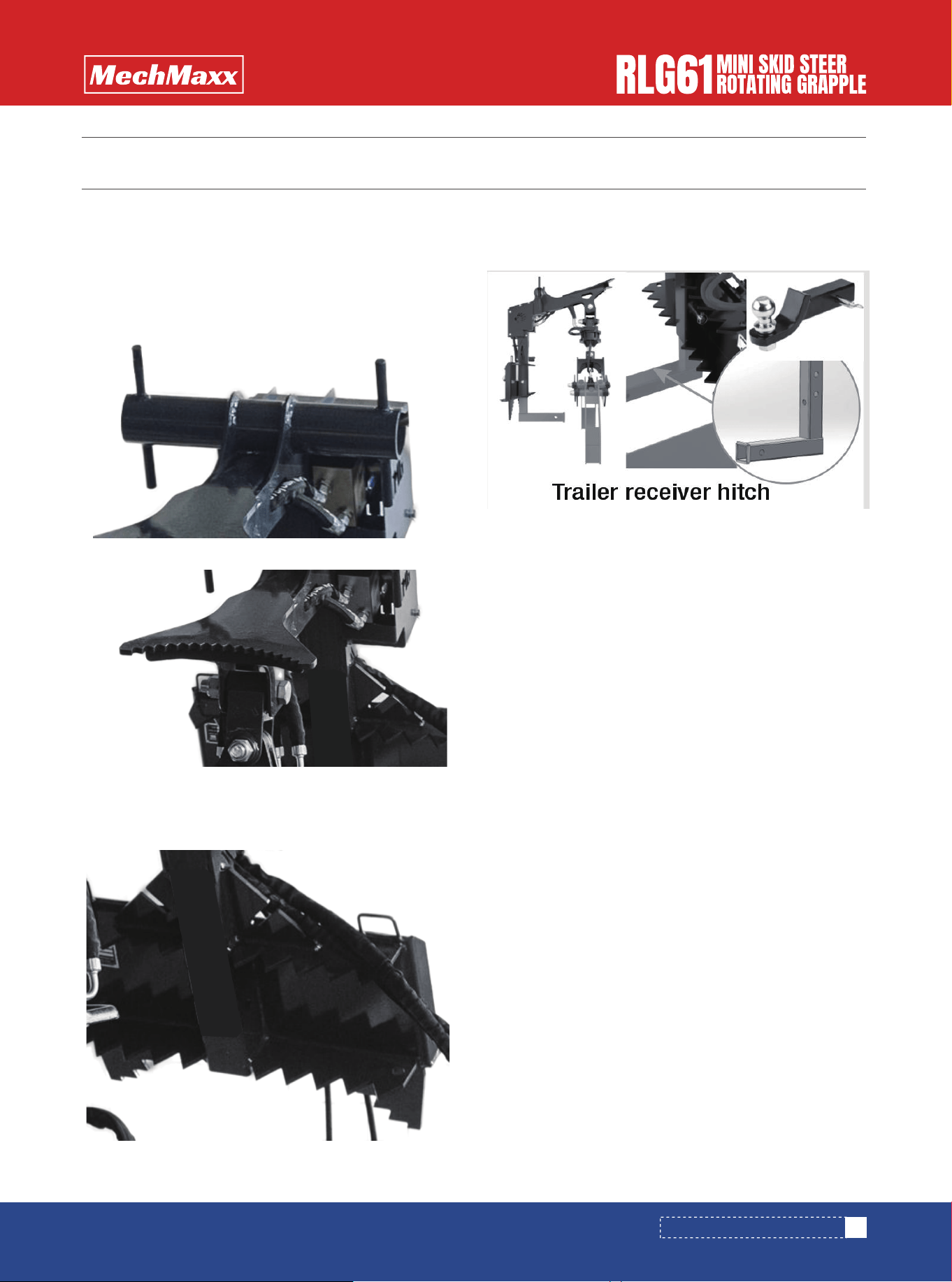
TREE PUSHER
LOG DOGS
RECEIVER HITCH
Unique Branch Manager Features
ROPE BOLLARD
Rated for 200 lbs. Never exceed
your equipment operating capacity
Never exceed your machine’s operating Capacity
Never exceed your machine’s operating Capacity
Never exceed your machine’s operating Capacity
Round stock inserts into the bottom of Grapple Hang-
er—Pin it In. Hook trailer safety chain to safety lock slot.
DO NOT USE ON INCLINES OR HILLS
12
www.mechmaxx.com
MAINTENANCE
MAINTENANCE
BEFORE EVERY USE
EVERY WEEK
AFTER EVERY SEASON
HYDRAULIC SYSTEM
BOLT TORQUE
Check that all fasteners (nuts, bolts, pins, keepers) are in
their right place and are tight. Inspect and replace any
worn, torn or missing safety decals. Investigate the
location of any oil leaks and repair.
Lubricate all joints with lithium grease.
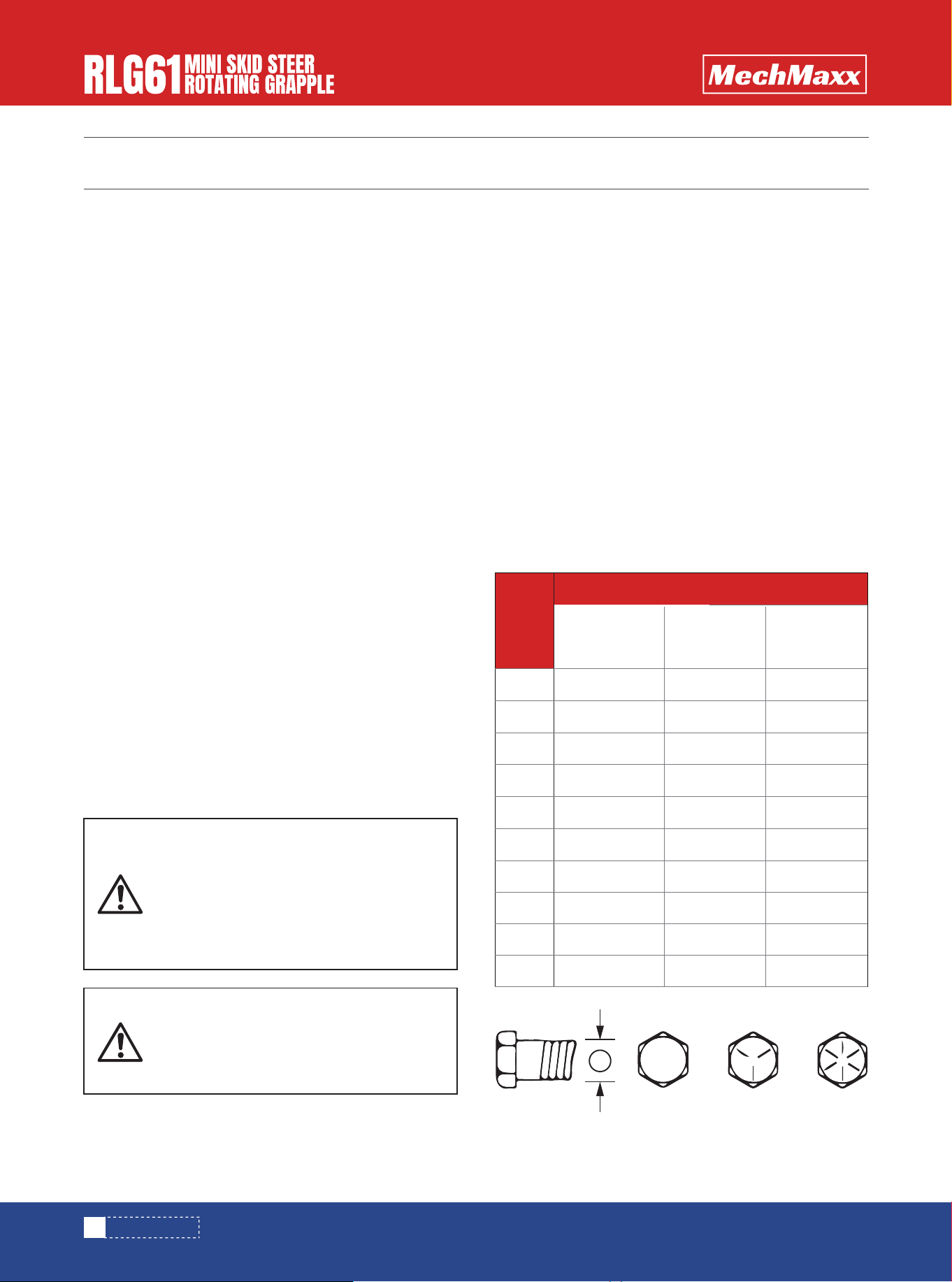
CHECKING BOLT TORQUE
The tables shown below give correct torque values for
various bolts and cap screws. Tighten all bolts to the
torques specified in chart unless otherwise noted. Check
tightness of bolts periodically, using bolt torque chart as
a guide. Replace hardware with the same strength bolt.
Torque figures indicated above are valid for non-greased
or non-oiled threads and heads unless otherwise speci-
fied. Therefore, do not grease or oil bolts or cap screws
unless otherwise specified in this manual. When using
locking elements, increase torque values by 5%.
* Torque value for bolts and cap screws are identified by
their head markings
Check the condition of the cutting edge and/or tooth
points. Order parts if the cutting edge or points are
becoming worn and replace as soon as possible.
Inspect the implement for any loose or worn parts that
may need to be replaced prior to the next season.
Visually inspect the cutting edge. Replace, if necessary.
Clean, sand & repaint any area that looks worn or
scratched to prevent further rusting. Use an equip-
ment-paint found at your local hardware store or building
center.
Replace any warning decals that have been lost or
damaged.
Store your implement in a shed or cover with a
water-proof tarp to protect it from the weather. Store in
an area not frequented by children.
Bolt
Diameter
SAE 2
SAE-2
A
SAE-5 SAE-8
N.m lb-ft N.m lb-ft N.m lb-ft
SAE 5 SAE 8
Bolt Torque
1/4"
5/16"
3/8"
7/16"
1/2"
9/16"
5/8"
3/4"
7/8"
1"
8
13
27
41
61
95
128
225
230
345
6
10
20
30
45
60
95
165
170
225
12
25
45
72
110
155
215
390
570
850
9
19
33
53
80
115
160
290
420
630
17
36
63
100
155
200
305
540
880
1320
12
27
45
75
115
165
220
400
650
970
ENGLISH TORQUE SPECIFICATIONS
Always release the hydraulic system pres-
sure from the hydraulic circuits prior to
removing the attachment or any hydraulic
system service work.
A small stream of oil from a pinhole leak
could penetrate your skin if contacted. To
avoid an accident that could result in
Death or Serious Injury, never use your
hand or other body parts in an attempt to
locate a hydraulic leak.

SPECIFICATION
• Universal Mini Skid Steer mount
• Lift Capacity : 3000lbs
• Hose Routing :Internal
• Hydraulic Cylinder:2“
• Rotator :3 Ton
• Hydraulic Flow 8-12GPM
• Hydraulic Pressure:2900 PSI
• Rotation 360
• Max static axial load:30Kn
• Open max size: 59”
• Net Weight:172kg
Bolt
Diameter
8.8
N.m lb-ft N.m lb-ft
10.9
Bolt Torque
M3
M4
M5
M6
M8
M10
M12
M14
M16
M20
M24
M30
M36
0.5
3
6
10
25
50
90
140
225
435
750
1495
2600
0.4
2.2
4
7
18
37
66
103
166
321
553
1103
1917
1.8
4.5
9
15
35
70
125
200
310
610
1050
2100
3675
1.3
3.3
7
11
26
52
92
148
229
450
744
1550
2710
METRIC TORQUE SPECIFICATIONS
SPECIFICATIONS & CAPACITIES
A
8.8 10.9
13
www.mechmaxx.com
MAINTENANCE

14
www.mechmaxx.com
PARTS DIAGRAM
PARTS LIST

15
www.mechmaxx.com
PARTS LIST
PARTS LIST
1
6
12
12
4
4
1
2
2
2
2
2
1
1
1
1
1
1
1
2
1
1
2
2
1
2
1
2
2
2
No. No.DESCRIPTION QTY
1
2
3
4
5
6
7
8
9
10
11
12
13
13-1
13-2
13-3
13-4
13-5
13-6
13-7
13-8
14
15
16
17
18
19
20
21
22
TORO Hanger Mount
Bolt M8*25
Washer 8
Washer 8
Nut M8
Bolt M8*20
Protective plate weldment 03
Bolt M4*10
Washer 4
Washer 4
Up Hanging pin
Lock pin 8
Electrical components
Electrical box
Switch box
Wire 1
Wire 2
Wire 3
2 pins connector (female)
Pin (female)
2 pin locking plate
Protective plate weldment
Bolt M24*140
Nut M24
Motor connection welding parts
Bolt M8*30
Valve block connection plate
Washer 10
Washer 10
Bolt M10*30
1
1
1
1
2
2
2
2
1
2
1
1
2
2
4
1
1
2
1
1
1
1
1
1
2
2
6
4
4
1
DESCRIPTION QTY
23
24
24-1
24-2
24-3
24-4
24-5
24-6
24-7
24-8
24-9
24-10
24-11
24-12
24-13
24-14
24-15
24-16
25
25-1
25-2
25-3
25-4
25-5
25-6
25-7
25-8
25-9
25-10
25-11
Protective plate 2 weldment
Hydraulic system
Motor
Oil cylinder components
Cylinder Hose L590
Motor Hose 01 L700
Motor Hose 02. L540
Oil inlet and outlet Hose L1800
Two position six way one-way control valve group
Hard tube hose
Flat Faced Couplers G1/2 Male
Flat Faced Couplers G1/2 Female
End Straight Joint M16*1.5-M16*1.5
End Straight Joint NPT1/2-M18*1.5
High voltage articulated joint G3/8-M18 * 1.5
Flat quick change male 1/2 rubber sleeve
Flat quick change female 1/2 rubber sleeve
45 degree combination joint G3/8-M16 * 1.5
Lower clamping ligand
Claw 1 weldment
Claw 2 weldment
Claw connection bracket welded parts
Connecting plate for oil cylinder 01
LOGO back panel
Oil cylinder sales
Claw connection pin
Oil cup M8 * 1-304
Washer 6
Nut M20
Bolt M24*100
No.

16
www.mechmaxx.com
1
4
4
1
1
No. DESCRIPTION QTY
25-12
25-13
25-14
25-15
26
Nut M24
Washer 6
Nut M6
Connecting plate for oil cylinder 02
Trailer connection welding parts
PARTS LIST