
ISC-nRF54L Module
Serial Port Configuration Detail
1

2 | P a g e
Revision History
Revision Description Date
1.0 Initial Release 17/03/2026
Table of Contents
1. Introduction .......................................................................................................... 3
2. Evaluation Kit ....................................................................................................... 3
3. Serial Port Setup .................................................................................................. 4
4. CLI for Radio Control ........................................................................................... 5
2
3 | P a g e
1. Introduction
ISC-nRF54L Module is an Integrated multi-purpose MCU functionality which
supports Nordic’s nRF54L Series SoCs which is suited to enable a broad range of
applications. The multiprotocol 2.4 GHz radio supports the latest Bluetooth® 6.0
features including Bluetooth Channel Sounding, as well as 802.15.4-2020 for
standards such as Thread, Matter, and Zigbee, and a proprietary 2.4 GHz mode
supporting up to 4 Mbps for higher throughput. The module integrates the
peripherals expected in a wireless microcontroller enabling many products to be
implemented with a single chip.
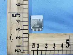
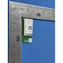
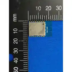
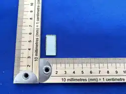
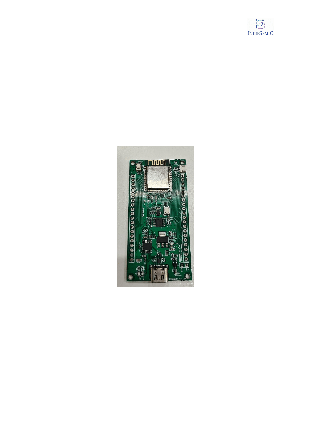
2. Evaluation Kit
Figure 1 EVK_ISC_nRF54L
Connect Type C port with USB to Type C connector with Host Computer
3
4 | P a g e
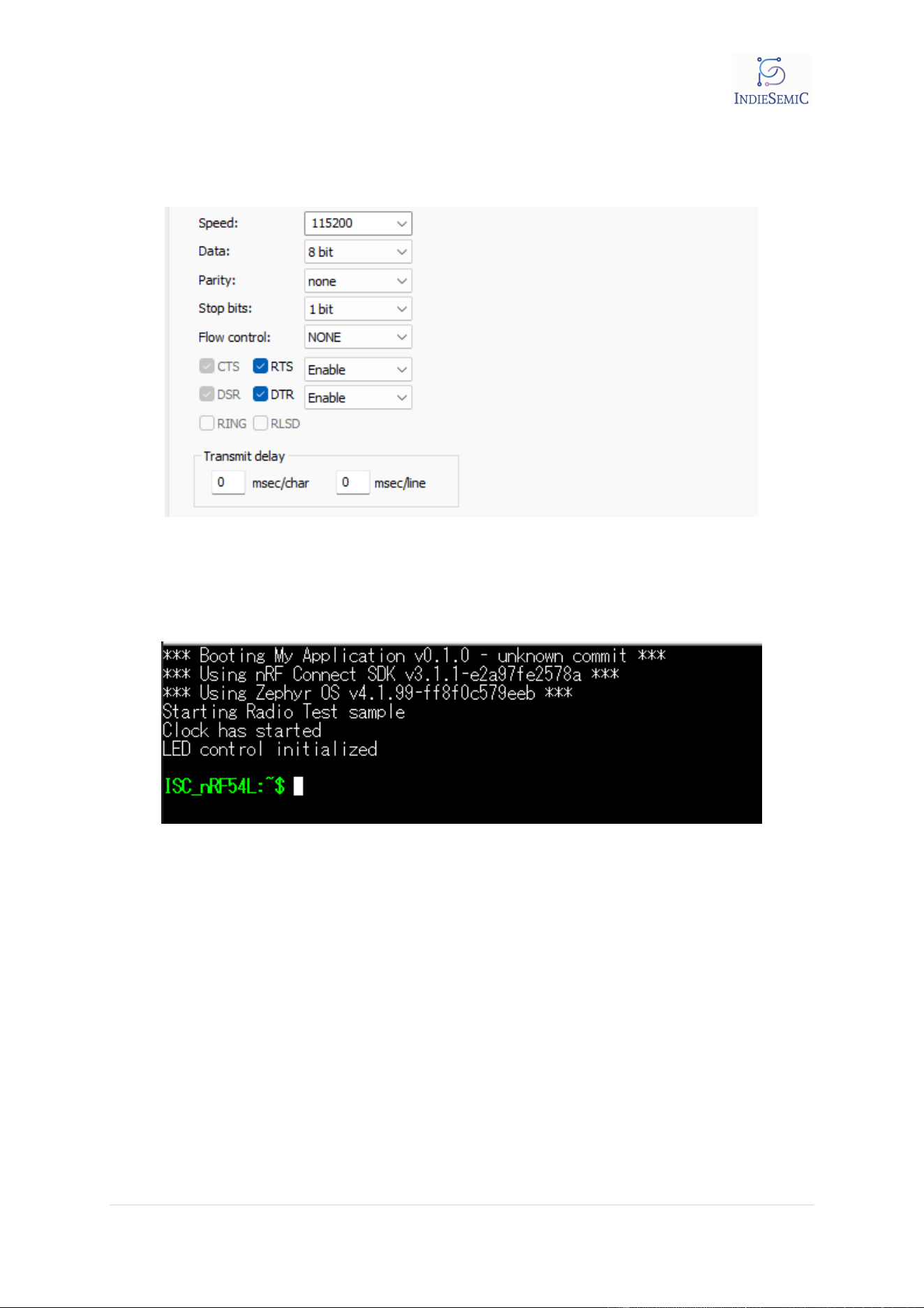
3. Serial Port Setup
Download any serial terminal and connect to it using following configuration.
Figure 2 Serial Port Configuration
For this document tera term is used.
After pressing reset on the board following output should be visible
Figure 3 Terminal Output 1
4
5 | P a g e
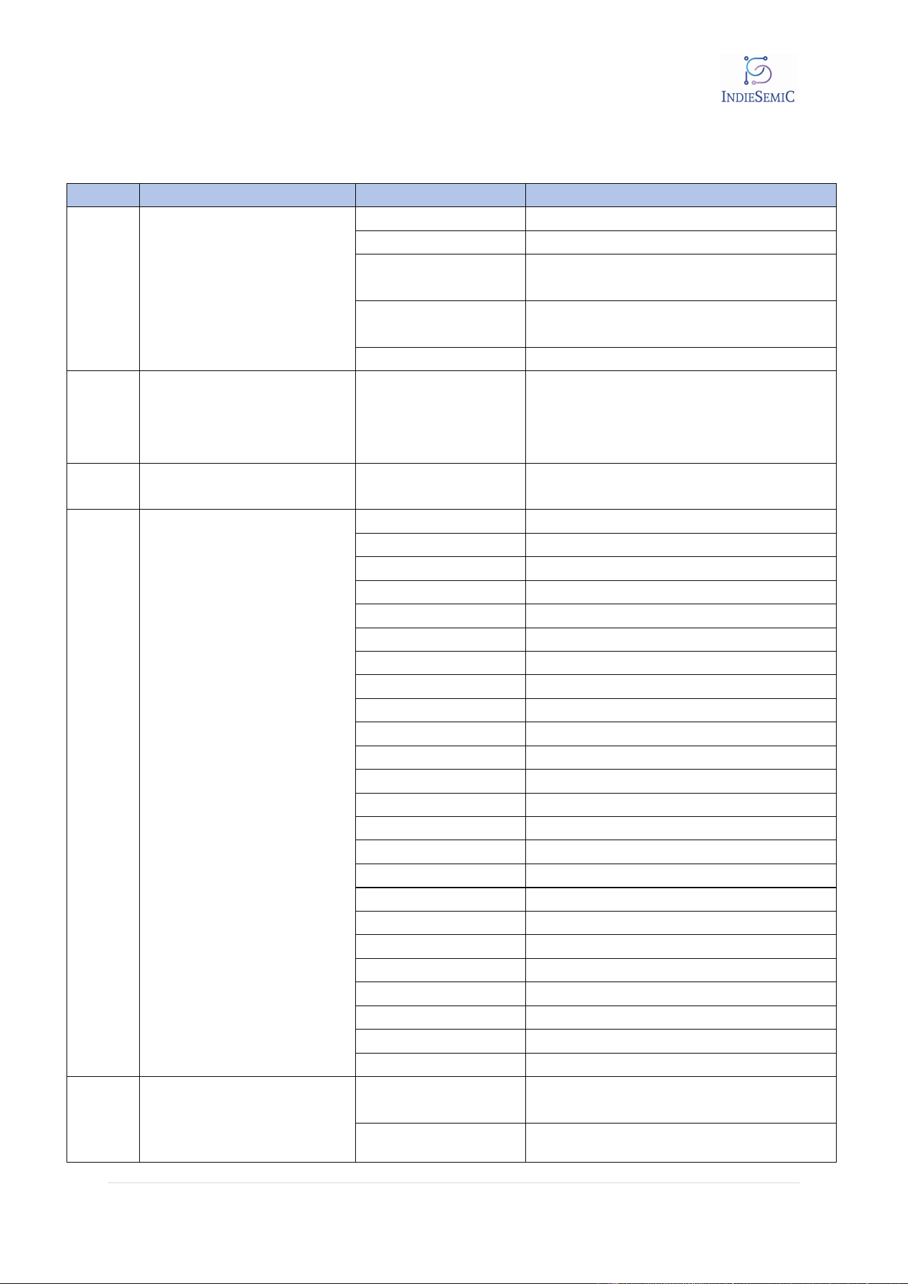
4. CLI for Radio Control
Please refer to CLI_Description.xlsx for usage description
Sr # Commands Sub-Commands Description
1 data_rate
ble_1Mbit
1 Mbit/s Bluetooth Low Energy
ble_2Mbit
2 Mbit/s Bluetooth Low Energy
ble_lr125Kbit
Long range 125 kbit/s TX, 125 kbit/s
and 500 kbit/s RX
ble_lr500Kbit
Long range 500 kbit/s TX, 125 kbit/s
and 500 kbit/s RX
ieee802154_250Kbit IEEE 802.15.4-2006 250 kbit/s
2 start_channel -
Start channel for the sweep or the
channel for the constant
carrier (in MHz as difference from
2400 MHz) <channel>
3 end_channel -
End channel for the sweep (in MHz as
difference from 2400 MHz) <channel>
4 output_power
pos8dBm +8 dBm TX Power
pos7dBm +7 dBm TX Power
pos6dBm +6 dBm TX Power
pos5dBm +5 dBm TX Power
pos4dBm +4 dBm TX Power
pos3dBm +3 dBm TX Power
pos2dBm +2 dBm TX Power
pos1dBm +1 dBm TX Power
pos0dBm 0 dBm TX Power
neg1dBm -1 dBm TX Power
neg2dBm -2 dBm TX Power
neg3dBm
-3 dBm TX Power
neg4dBm
-4 dBm TX Power
neg5dBm
-5 dBm TX Power
neg6dBm -6 dBm TX Power
neg7dBm -7 dBm TX Power
neg8dBm -8 dBm TX Power
neg9dBm
-9 dBm TX Power
neg10dBm
-10 dBm TX Power
neg12dBm
-12 dBm TX Power
neg14dBm -14 dBm TX Power
neg16dBm -16 dBm TX Power
neg18dBm -18 dBm TX Power
neg20dBm
-20 dBm TX Power
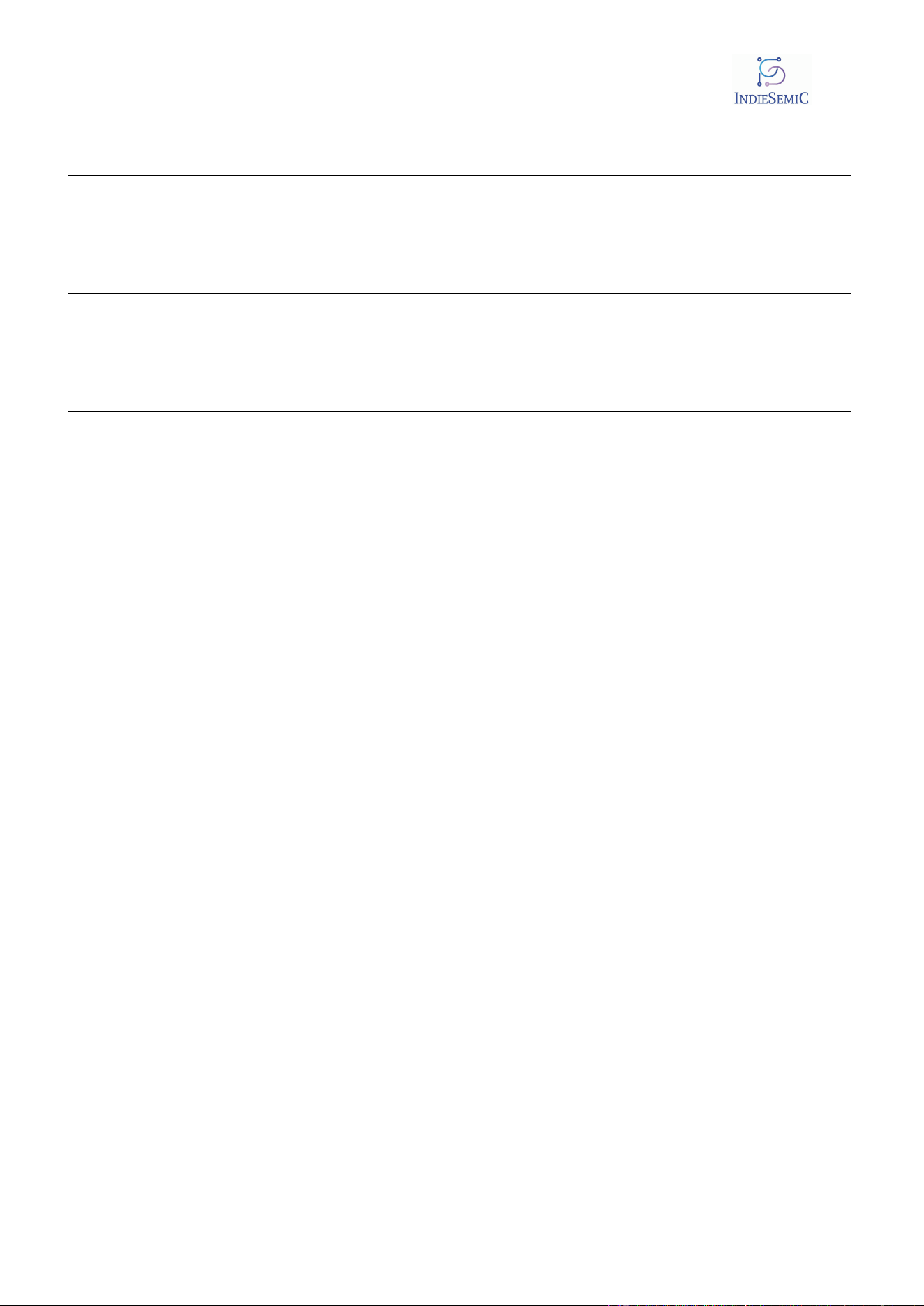
5 transmit_pattern
pattern_random Set the transmission pattern to random.
pattern_11110000
Set the transmission pattern to
11110000.
5
6 | P a g e
pattern_11001100
Set the transmission pattern to
11001100.
6 start_tx_carrier - Starts unmodulated radio transmission
7 start_tx_modulated_carrier
<number of
packets>
Starts modulated radio transmission for
defined number of packets
8 start_tx_sweep -
Starts frequency hopping in between
start and end channels
9 time_on_channel -
Time on each channel in ms (between
1 and 99) <time>
10 start_rx
<number of
packets>
Starts reception for radio signals on
selected frequency
11 cancel - terminate any on going radio
6
FCC Warning
15.19 Labeling requirements.
This device complies with part 15 of the FCC Rules. Operation is subject to the following two
conditions: (1) This device may not cause harmful interference, and (2) this device must accept
any interference received, including interference that may cause undesired operation.
15.21 Information to user.
Any Changes or modifications not expressly approved by the party responsible for compliance
could void the user's authority to operate the equipment.
15.105 Information to the user.
Note: This equipment has been tested and found to comply with the limits for a Class B digital
device, pursuant to part 15 of the FCC Rules. These limits are designed to provide reasonable
protection against harmful interference in a residential installation. This equipment generates
uses and can radiate radio frequency energy and, if not installed and used in accordance with the
instructions, may cause harmful interference to radio communications. However, there is no
guarantee that interference will not occur in a particular installation. If this equipment does cause
harmful interference to radio or television reception, which can be determined by turning the
equipment off and on, the user is encouraged to try to correct the interference by one or more of
the following measures:
-Reorient or relocate the receiving antenna.
-Increase the separation between the equipment and receiver.
-Connect the equipment into an outlet on a circuit different from that to which the receiver is
connected.
-Consult the dealer or an experienced radio/TV technician for help.
FCC RF Radiation Exposure Statement:
1.
This Transmitter must not be co-located or operating in conjunction with any other antenna or
transmitter.
2.This equipment complies with RF radiation exposure limits set forth for an uncontrolled
environment.
This equipment should be installed and operated with minimum distance 20cm between the
radiator and your body.
Additional Section: Integration instructions for host product manufacturers
according to KDB 996369 D03 OEM Manual v01
2.1 Conditions on using
INDIESEMIC PRIVATE LIMITED
regulatory approvals:
A. Customer must ensure that its product (The ”CUSTOMER Product”) is electrically
identical to INDIESEMIC PRIVATE LIMITED
reference designs. Customer
acknowledges that
any modifications to INDIESEMIC PRIVATE LIMITED reference designs may invalidate
regulatory approvals in relation to the CUSTOMER Product, or may necessitate notifications to the
relevant regulatory authorities.
B. Customer is responsible for ensuring that antennas used with the product are of the
same type, with same or lower gains as approved and providing antenna reports to
INDIESEMIC PRIVATE LIMITED
C. Customer is responsible for regression testing to accommodate changes to INDIESEMIC
PRIVATE LIMITED reference designs, new antennas, and portable RF exposure safety
testing/approvals.
D. Appropriate labels must be affixed to the CUSTOMER Product that comply with
applicable regulations in all respects.
E. A user’s manual or instruction manual must be included with the customer product
that contains the text as required by applicable law. Without limitation of the foregoing,
an example (for illustration purposes only) of possible text to include is set forth below:
7
2.2 List of applicable FCC rules (customers' product must also compliant with
these rules)
FCC Part 15 Subpart C 15.247
2.3 Specific operational use conditions
Operation Frequency: 2402MHz to 2480MHz
Number of Channels: 40
Modulation Type: GFSK
Antenna Type: PCB Antenna
Antenna Gain#: -2.2dBi
The module can be used for mobile applications with the same ant. type with
maximum -2.2dBi antenna. The host manufacturer installing this module into their product must
ensure that the final composite product complies with the FCC requirements by a technical assessment
or evaluation to the FCC rules, including the transmitter operation. The host manufacturer has to be
aware not to provide information to the end user regarding how to install or remove this RF module in
the user's manual of the end product which integrates this module. The end user manual shall include
all required regulatory information/warning as show in this manual. If the end product manufacturer
use it to a portable product, please provide the SAR compliance.
2.4 Limited module procedures
Not applicable. The module is a Single module and complies with the requirement of FCC Part 15.212.
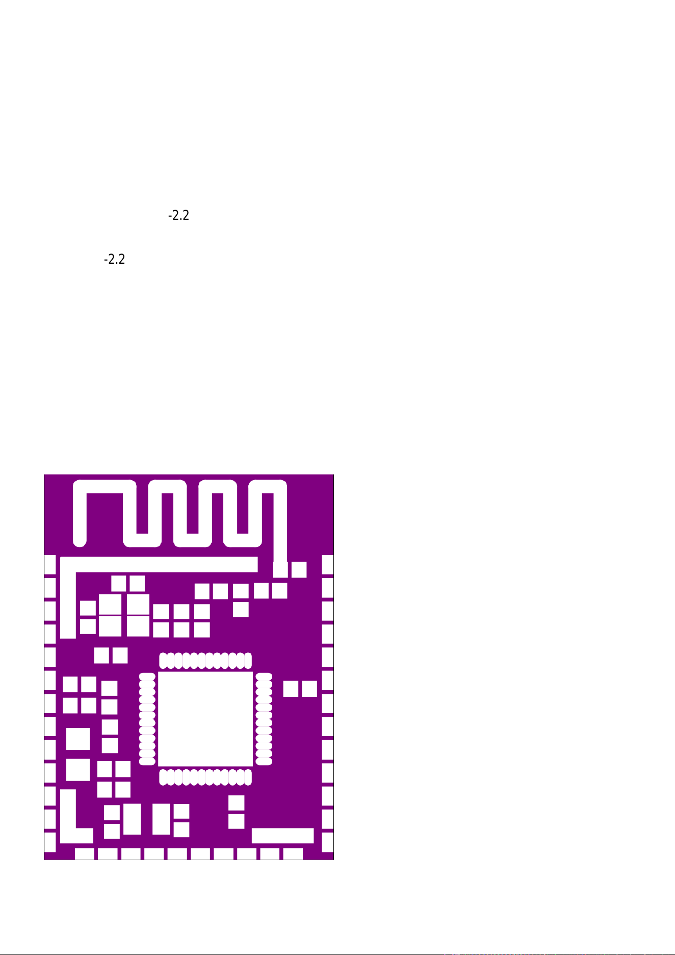
2.5 Trace antenna designs
8

Data Rate : 1Mpbs/2Mpbs
Antenna Type: PCB Antenna
Antenna Gain: -2.2Bi
Host manufacturer must perform test of radiated & conducted emission and spurious emission, etc
according to the actual test modes for a stand-alone modular transmitter in a host, as well as for
multiple simultaneously transmitting modules or other transmitters in a host product. If no other
module used and no change to this module, the product can only to compliance with FCC part 15B to
meet the sale requirement. Only when all the test results of test modes comply with FCC requirements,
then the end product can be sold legally.
2.10 Additional testing, Part 15 Subpart B disclaimer
The modular transmitter is only FCC authorized for FCC Part 15 Subpart C 15.247 that the host
product manufacturer is responsible for compliance to any other FCC rules that apply to the host not
covered by the modular transmitter grant of certification. If the grantee markets their product as being
Part 15 Subpart B compliant (when it also contains unintentional-radiator digital circuity), then the
grantee shall provide a notice stating that the final host product still requires Part 15 Subpart B
compliance testing with the modular transmitter installed.
9
2.6 RF exposure considerations
The device can be used in mobile exposure condition and if RF exposure statement or module layout is
changed, then the host product manufacturer required to take responsibility of the module through a
change in FCC ID or new application. The FCC ID of the module cannot be used on the final product. In
these circumstances, the host manufacturer will be responsible for re-evaluating the end product
(including the transmitter) and obtaining a separate FCC authorization.This equipment should be
installed and operated with minimum distance 20cm between theradiator and your body.
2.7 Antennas
Antenna Type: PCB antenna
Antenna Gain: -2.2dBi
This device is intended only for host manufacturers under the following conditions:
The transmitter module may not be co-located with any other transmitter or antenna;
The module shall be only used with the PCB antenna that has been originally tested and certified with
this module. The antenna must be either permanently attached or employ a ‘unique’antenna coupler.
As long as the conditions above are met, further transmitter test will not be required. However, the
host manufacturer is still responsible for testing their end product for any additional compliance
requirements required with this module installed.
2.8 Label and compliance information
Host product manufacturers need to provide a physical or e-label stating “Contains
FCC ID:2BVP2-NRF54L15” with their finished product.
2.9 Information on test modes and additional testing requirements
Operation Frequency: 2402MHz to 2480MHz
Number of Channels: 40
Modulation Type: GFSK