HL3430SG WiFi+LCD Module Specification
1. General Description
HL3430SG module is a low-power, high-reliability Wi-Fi+LCD module for Smart home appliance products.
This module uses BK7256 solution, support 802.11 b/g/n/ax, 1T1R, Wi-Fi antenna using onboard antenna,
support URAT interface. This module adopts a single WiFi chip to achieve intelligent functions such as
networking and TFT LCD display, which has cost advantages
2. Features
2.1. System Function
Main Chipset
BK7256
Operating Frequency
2402MHz—2480MHz
Wi-Fi Standard
IEEE802.11 b/g/n/ax, 1T1R
Bluetooth
BLE 5.2
Modulation
WiFi:
802.11b:DBPSK,DQPSK,CCK for DSSS
802.11g:BPSK,QPSK,16QAM,64QAM for OFDM
802.11n:BPSK,QPSK,16QAM,64QAM for OFDM
802.11ax: BPSK,QPSK,16QAM,64QAM for OFDMA
Interface Definition
51Pin LCC
Host Interface
UART
Dimension
35(mm)*18(mm)*3.65(mm)( tolerance +/-0.3)
Antenna
PCB antenna
Operation Temperature
3.3V±0.3V
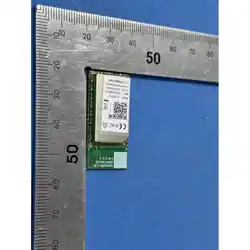
2.2. Product Picture
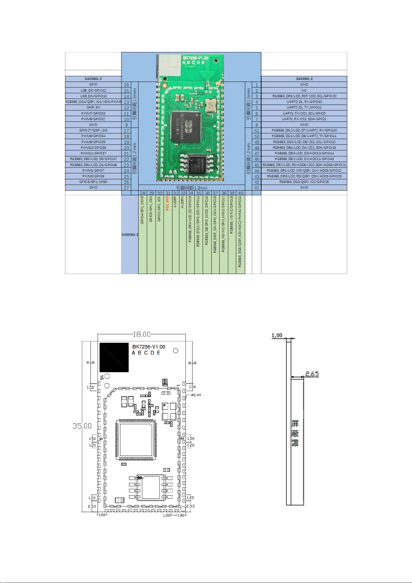
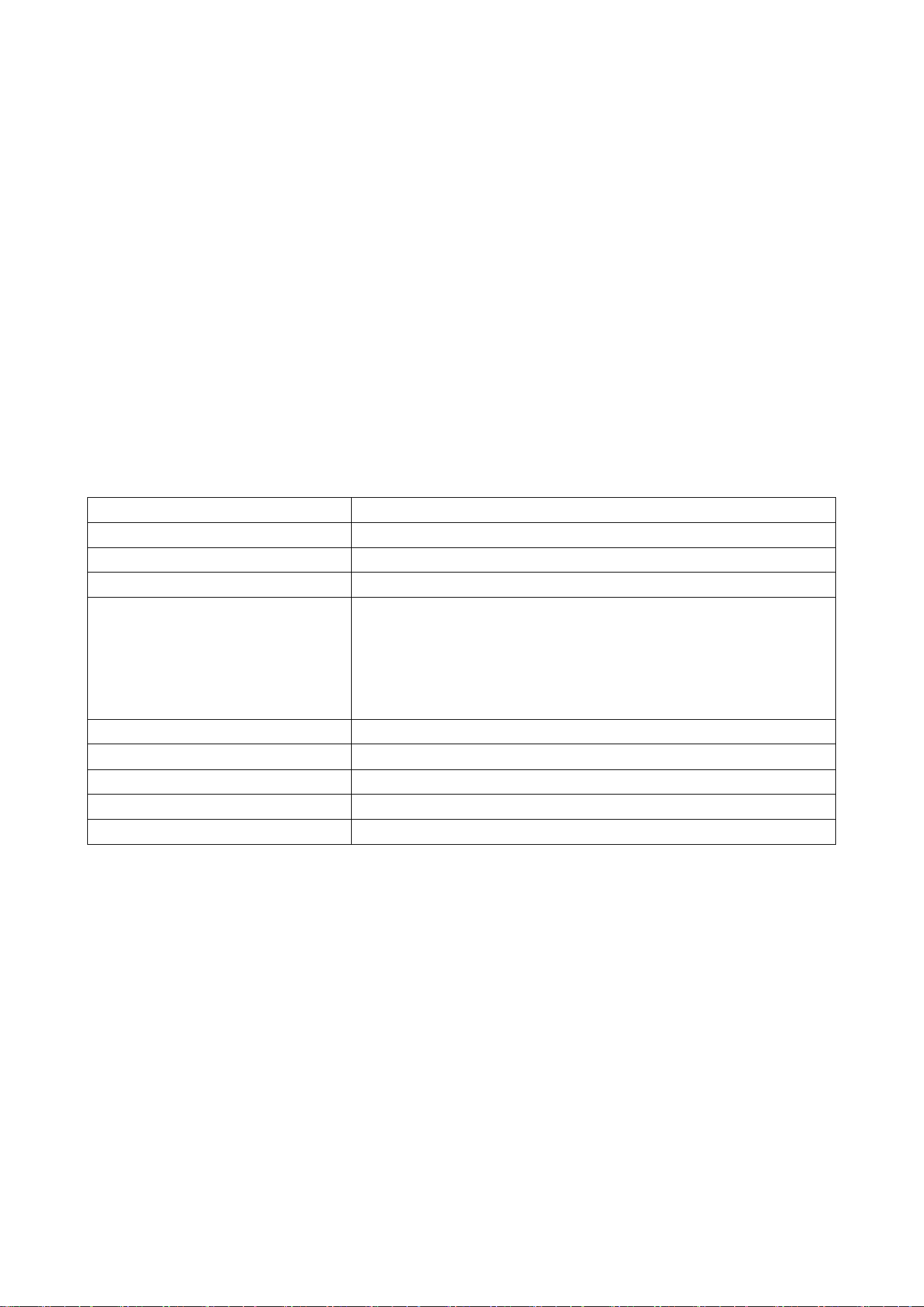
2.3. Size & PIN Define
SN
Definition
Description
Pin1
GND
Ground
Pin2
NC
Pin3
RGB565_DR3/LCD_RST/I2C0_SCL/GPIO20
LCD interface
Pin4
UART0_DL_RX/GPIO10
UART communication and pro
gram download
Pin5
UART0_DL_TX_GPIO11
UART communication and pro
gram download
Pin6
UART1_TX/I2C1_SCL/GPIO0
UART debugging interface
Pin7
UART1_RX/I2C1_SDA/GPIO1
UART debugging interface
Pin8
GND
Ground
Pin9
GND
Ground
Pin10
PWM6/GPIO32
Pin11
PWM7/GPIO33
Pin12
CHIP_EN
Reset, low voltage enabled, high
voltage off
Pin13
RGB565_DG4/QSPI_IO1/IrDA/PWM5
LCD interface
Pin14
USB_DN/GPIO13
Pin15
USB_DP/GPIO12
Pin16
GPIO
Pin17
GPIO27/QSPI_IO3
Pin18
PWM8/GPIO34
Pin19
PWM9/GPIO35
Pin20
PWM10/GPIO36
Pin21
PWM11/GPIO37
Pin22
RGB565_DB0/LCD_D0/GPIO47
LCD interface
Pin23
RGB565_DB1/LCD_D1/GPIO46
LCD interface
Pin24
PWM1/GPIO7
Pin25
PWM0/GPIO6
Pin26
GPIO5/SPI1_MISO
Pin27
GPIO
Pin28
GPIO4/SPI1_MOSI
Pin29
GPIO3/SPI1_CSN
Pin30
GPIO2/SPI1_SCK
Pin31
VCC_3V3
Power In Typ:3.3V
Pin32
AUDRP
Audio positive output
Pin33
AUDRN
Audio negative output
Pin34
RGB565_DR4/LCD_CS/GPIO19
LCD interface
Pin35
RGB565_DCLK/SPI0_SCK/GPIO14
LCD interface
Pin36
RGB565_DE/SPI0_MOSI_GPIO16
LCD interface
Pin37
RGB565_DISP_ON/SPI0_CSN/GPIO15
LCD interface
3. RF Specification
number
Item for WiFi
specification
1
Output power
802.11b CCK 11Mbps:17(typical)
802.11g OFDM 54Mbps@2.4GHz:14dBm(typical)
802.11n HT20 MCS7@2.4GHz:13dBm(typical)
802.11ax HE20 MCS7@2.4GHz:13dBm(typical)
2
antenna
Gain:1dBi efficiency:50%
3
Frequency Range
2402MHz—2480MHz
4
EVM
802.11b, CCK, 11Mbps: 16%
802.11g, OFDM, 54Mbps: ≤-30dB
802.11n, HT20, MCS7: ≤-30dB
802.11ax, HE20, MCS7: ≤-30dB
5
RS
802.11b @ 11Mbps: (Max) : -84dBm , (Typical) : -87dBm
(PER<8%)
802.11g @ 54Mbps: (Max.) : -69dBm , (Typical) : -75dBm
(PER<10%)
802.11n @ MCS7 (2.4g HT20): (Max) : -67dBm , (Typical) : -
73dBm (PER<10%)
802.11ax @ MCS7 (2.4g HE20): (Max) : -65dBm , (Typical) : -
72dBm (PER<10%)
6
Frequency accuracy
≤15×10
-6
number
Item for BLE
specification
8
standard
BLE 5.2
Pin38
RGB565_HSYNC/SPI0_MISO/GPIO17
LCD interface
Pin39
RGB565_VSYNC/GPIO18
LCD interface
Pin40
RGB565_DG5/QSPI_IO0/ADC2/PWM4/GPIO24
LCD interface
Pin41
GND
Pin42
RGB565_DG3/QSPI_IO2/GPIO26
LCD interface
Pin43
RGB565_DR0/LCD_RD/QSPI_CSN/ADC3/GPIO23
LCD interface
Pin44
RGB565_DR1/LCD_WR/QSPI_CLK/ADC5/GPIO22
LCD interface
Pin45
RGB565_DR2/LCD_RS/ADC6/I2C0_SDA/ADC6/GPIO21
LCD interface
Pin46
RGB565_DB2/LCD_D2/ADC11/GPIO45
LCD interface
Pin47
RGB565_DB3/LCD_D3/ADC10/GPIO44
LCD interface
Pin48
RGB565_DB4/LCD_D4/I2C1_SDA/GPIO43
LCD interface
Pin49
RGB565_DG0/LCD_D5/I2C1_SCL/GPIO42
LCD interface
Pin50
RGB565_DG1/LCD_D6/UART2_TX/GPIO41
LCD interface
Pin51
RGB565_DG2/LCD_D7/UART2_RX/GPIO40
LCD interface
9
Frequency Range
2402MHz—2480MHz
10
Data rate
1Mbps,2Mbps
11
modulation
GFSK
12
Output power
6dBm(typical)
13
RS
BLE1M:-95dBm(typical); BLE2M:-92dBm(typical)
4. Antenna
4.1. Antenna Characteristic
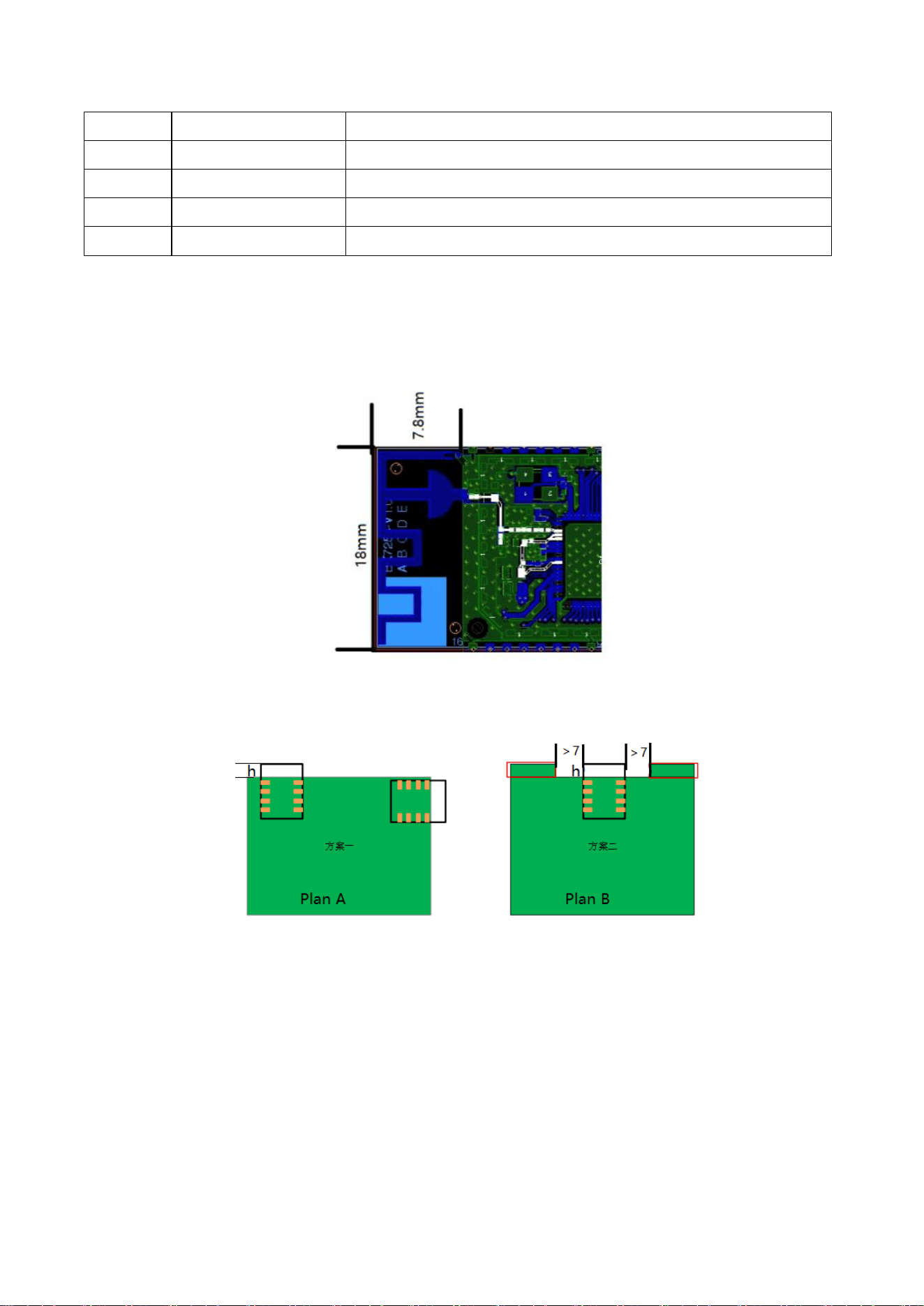
4.2. Antenna Position Requirements
Note:
Plan A:WiFi module is placed on the side of the power board.
1. The antenna part extends out of the power board side height, h=7.8mm.
2. Do not enclose the antenna with a metal shell and do not place metal components close to the antenna
within 15mm.
Plan B:The WiFi module is placed in the power board, and the antenna is hollowed out around.
1. The distance between the antenna and the power board edge, d>7mm.
2. The antenna part extends out of the power board side height, h=7.8mm.
3. Do not enclose the antenna with a metal shell and do not place metal components close to the antenna
within 15mm.


FCC&IC regulatory compliance statement
FCC Warning:
This device complies with Part 15 of the FCC Rules. Operation is subject to the following two
conditions:
(1) This device may not cause harmful interference, and
(2) This device must accept any interference received, including interference that may cause
undesired operation.
IC Warning:
This device contains licence-exempt transmitter(s)/receiver(s) that comply with Innovation,
Science and Economic Development Canada’s licence-exempt RSS(s). Operation is subject to the
following two conditions:
(1) This device may not cause interference.
(2) This device must accept any interference, including interference that may cause undesired
operation of the device.
l'appareil contient des émetteurs/récepteurs exempts de licence qui sont conformes aux CNR
exempts de licence d’Innovation, Sciences et Développement économique Canada. L’exploitation
est soumise aux deux conditions suivantes :
(1) l'appareil ne doit pas produire de brouillage,
(2) l'utilisateur de l'appareil doit accepter tout brouillage radioélectrique subi, même si le
brouillage est susceptible d'en compromettre le fonctionnement.
This equipment complies with IC RSS-102 radiation exposure limits set forth for an uncontrolled
environment. This equipment should be installed and operated with minimum distance 20cm
between the radiator & your body.
ce matériel est conforme aux limites de dose d'exposition aux rayonnements, CNR-102 énoncée
dans un autre environnement.cette eqipment devrait être installé et exploité avec distance
minimale de 20 entre le radiateur et votre corps.
CAN ICES-3 (B)/NMB-3(B)
Information to user
Warning: changes or modifications not expressly approved by the party responsible for compliance could void the
user’s authority to operate the equipment.
RF Exposure compliance statement
This Module complies with FCC radiation exposure limits set forth for an uncontrolled environment. This equipment
should be installed and operated with a minimum distance of 20cm between the radiator and your body. This

transmitter must not be co-located or operating in conjunction with any other antenna or transmitter.
Labelling Instruction for Host Product Integrator
Please notice that if the FCC and IC identification number is not visible when the module is installed inside another
device, then the outside of the device into which the module is installed must also display a label referring to the
enclosed module. For FCC, this exterior label should follow “Contains FCC ID: 2A4A3-HL3430”. In accordance with
FCC KDB guidance 784748 Labeling Guidelines. For IC, this exterior label can use wording “Contains IC: 32735-
HL3430”.
§ 15.19 Labelling requirements shall be complied on end user device.
Labelling rules for special device, please refer to §2.925, § 15.19 (a)(5) and relevant KDB publications. For E-label,
please refer to §2.935.
Installation Notice to Host Product Manufacturer
The OEM integrator is responsible for ensuring that the end-user has no manual instruction to remove or install
module.
The module is limited to installation in mobile application, a separate approval is required for all other operating
configurations, including portable configurations with respect to §2.1091 and difference antenna configurations.
Antenna Change Notice to Host manufacturer
If you desire to increase antenna gain and either change antenna type or use same antenna type certified, a Class II
permissive change application is required to be filed by us, or you (host manufacturer) can take responsibility
through the change in FCC ID&IC ID (new application) procedure followed by a Class II permissive change application.
FCC other Parts, Part 15B Compliance Requirements for Host product
manufacturer
This modular transmitter is only FCC authorized for the specific rule parts listed on our grant, host product
manufacturer is responsible for compliance to any other FCC rules that apply to the host not covered by the modular
transmitter grant of certification.
Host manufacturer in any case shall ensure host product which is installed and operating with the module is in
compliant with Part 15B requirements.
Please note that For a Class B or Class A digital device or peripheral, the instructions furnished the user manual of
the end-user product shall include statement set out in §15.105 Information to the user or such similar statement
and place it in a prominent location in the text of host product manual. Original texts as following:

For Class B
Note: This equipment has been tested and found to comply with the limits for a Class B digital device,
pursuant to part 15 of the FCC Rules. These limits are designed to provide reasonable protection against
harmful interference in a residential installation. This equipment generates, uses and can radiate radio
frequency energy and, if not installed and used in accordance with the instructions, may cause harmful
interference to radio communications. However, there is no guarantee that interference will not occur in a
particular installation. If this equipment does cause harmful interference to radio or television reception, which
can be determined by turning the equipment off and on, the user is encouraged to try to correct the
interference by one or more of the following measures:
—Reorient or relocate the receiving antenna.
—Increase the separation between the equipment and receiver.
—Connect the equipment into an outlet on a circuit different from that to which the receiver is connected.
—Consult the dealer or an experienced radio/TV technician for help.
For Class A
Note: This equipment has been tested and found to comply with the limits for a Class A digital device,
pursuant to part 15 of the FCC Rules. These limits are designed to provide reasonable protection against
harmful interference when the equipment is operated in a commercial environment. This equipment
generates, uses, and can radiate radio frequency energy and, if not installed and used in accordance with
the instruction manual, may cause harmful interference to radio communications. Operation of this equipment
in a residential area is likely to cause harmful interference in which case the user will be required to correct
the interference at his own expense.