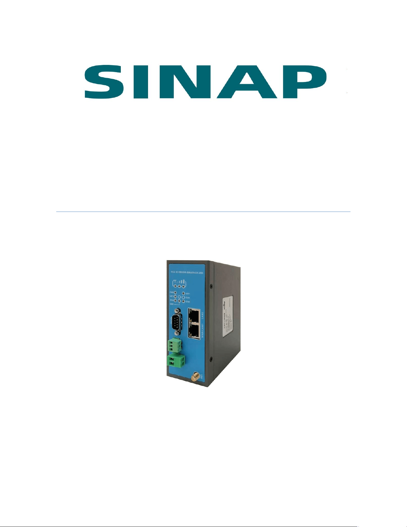
SINAPACK 200 PLC SINAPACK
200
User Manual

SINAPACK 200 User Manual
2
This manual applies to the following models, and the corresponding
networks supported by the models are listed in the table below:
Model
Network
SINAPACK 200
WIFI and WAN cable networks, use WAN by
default

SINAPACK 200 User Manual
3
Table of Contents
1. Product Introduction .................................................................................................................. 4
1.1 Brief Introduction ............................................................................................................. 4
1.2 Product Outlook................................................................................................................. 6
1.3 Standard Accessories ...................................................................................................... 7
1.4 Dimension ............................................................................................................................ 8
1.5 Working Mechanism ........................................................................................................ 9
1.6 Specifications ................................................................................................................... 10
1.6.1 Technical Parameters ........................................................................................ 10
1.6.2 Indicator Light Description .............................................................................. 10
1.6.3 Serial Port Definition ......................................................................................... 11
1.6.4 RESET Button ....................................................................................................... 12
1.7 Typical Usecases ............................................................................................................. 12
2. Device Configurations ............................................................................................................. 14
2.1 Configurations .................................................................................................................. 14
2.1.1 Preparation ............................................................................................................ 14
2.1.2 Configuring SINAPACK 200............................................................................. 14
2.2 Configuration Parameters ........................................................................................... 24
2.3 Restore to Default .......................................................................................................... 25
2.4 Firmware Update ............................................................................................................ 26
2.5 Remote Configurations ................................................................................................. 28
Appendix 1: Use SINAPACK 200 Virhub Functionality to Implement PLC Program
Remote Update ............................................................................................................................... 31
Appendix 2: Use SINAPACK 200 Serial Functionality to Implement PLC Program
Remote Update ............................................................................................................................... 41
Appendix 3: Configure SINAPACK 200 to Access Internet via Cable/WIFI .............. 47
Appendix 4: Use VNC and SINAPACK 200 to Access and Control Devices Remotely
.............................................................................................................................................................. 58
Appendix 5: Use SINAPACK 200 IP Virtual Mapping together with Virhub to
Distinguish Devices with Same IP............................................................................................ 67
Appendix 6: SINAPACK 200’s MODBUS TCP Interface Description ............................. 72
Appendix 7: SINAPACK 200’s Enhanced DMZ Function .................................................. 74

SINAPACK 200 User Manual
4
1. Product Introduction
This chapter mainly introduces the outlook, accessories, dimension,
specifications and mechanism of SINAPACK 200.
1. Brief Introduction
2. Product Outlook
3. Accessories
4. Dimension
5. Working Mechanism
6. Specifications
7. Typical Usecases
1.1 Brief Introduction
SINAPACK 200 is an industrially designed product, and is especially
used with PLCs. SINAPACK 200 provides program download and data
acquisition functionalities for PLCs that have RJ-45 Ethernet interface,
or RS232/RS485 serial interfaces. It supports PLCs from Siemens,
Mitsubishi, Omron, Panasonic, Delta, Fatek, etc. SINAPACK 200
connects with WIFI/WAN network, and with PLC programming tools or
SCADA software to implement remote program download and data
acquisition.
SINAPACK 200 is an enhanced version of PLC-505. Compared with
PLC-505, its panel is more compact, and has stand-up shape in
response to customers’ request that can massively save installation
space.
SINAPACK 200 has two RJ-45 Ethernet interfaces, one of which (LAN1)
can be used as WAN as well, one RS232 and one RS485 serial
interfaces. Ethernet interfaces and serial interfaces can be used at the
same time.
SINAPACK 200 has WIFI functionality, and supports 802.11b/g/n
protocol. In theory the highest speed can be 150Mbps. Mobile phones,
PCs or other devices that have WIFI functionality can bind SINAPACK
200’s WIFI access point and share Internet access via SINAPACK 200.

SINAPACK 200 User Manual
5
This greatly extends the number of devices that can connect with
SINAPACK 200 at the same time.
SINAPACK 200 can use WAN or WIFI network: in case cable network is
available, WAN (LAN1) port can be used to access cable network; and
in case WIFI is available, SINAPACK 200 can be configured to access
internet via WIFI. WAN and WIFI are all supported by SINAPACK 200,
this greatly facilitates customer’s project deployment that customers
do not have to choose different devices from different suppliers
because of different network access at the spot. This can not only save
procurement cost, but also reduce maintenance effort for the projects.
SINAPACK 200 is easy to use, and is plug-n-play without any
configuration. Together with eTung’s eYun platform and
Virhub/Vircom software, it can be easy to integrate with PLC
programming software, and there is no extra integration effort.
SINAPACK 200 is stable and easy-to-use, thus greatly facilitates
project deployment.
SINAPACK 200 User Manual
6
1.2 Product Outlook
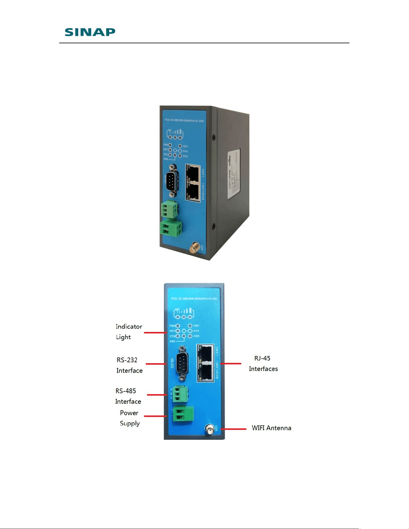
Figure 1-1: SINAPACK 200 whole view
Figure 1-2: SINAPACK 200 panel view
SINAPACK 200 User Manual
7
1.3 Standard Accessories
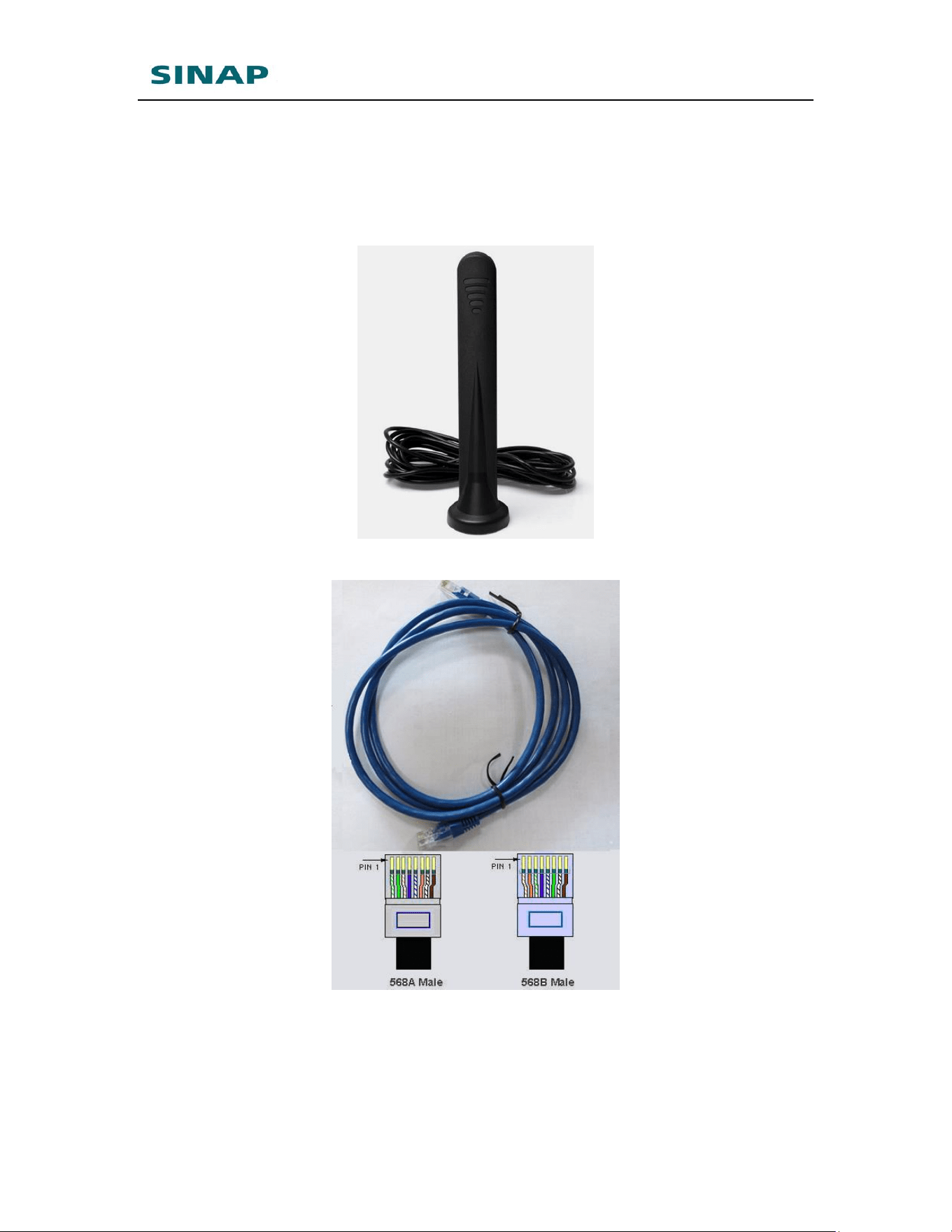
Figure 1-3: WIFI dual-frequency antenna
Figure 1-4: Cross cable
NOTE: The accessories may be different because of different models and
customer requirements, the figures above are just for reference.
SINAPACK 200 User Manual
8
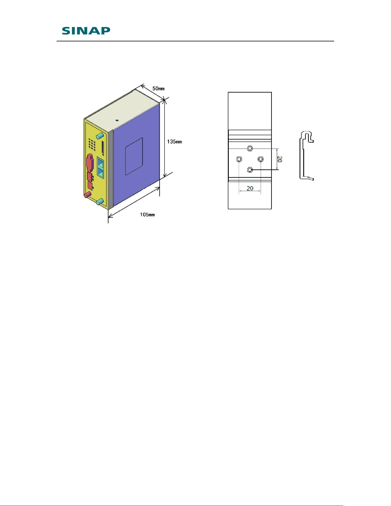
1.4 Dimension
Figure 1-5: SINAPACK 200 dimension
SINAPACK 200 User Manual
9
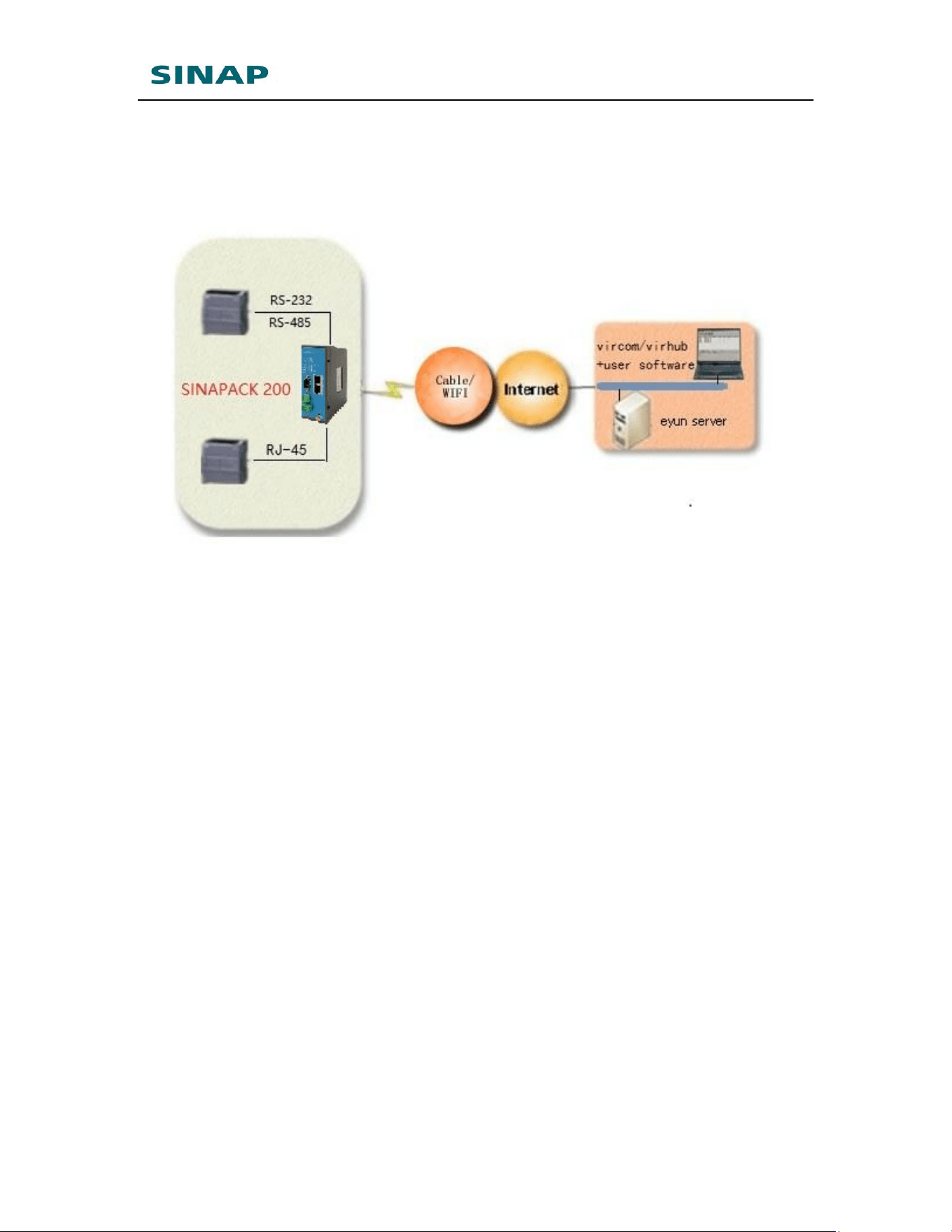
1.5 Working Mechanism
Figure 1-6: SINAPACK 200 working mechanism
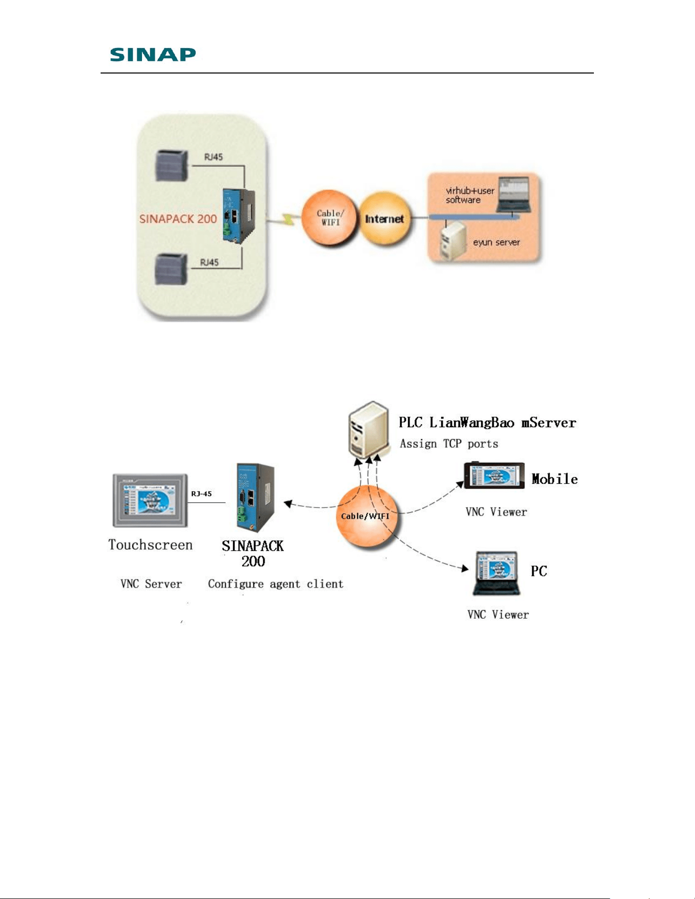
SINAPACK 200 has RJ45 Ethernet interface and RS232/RS485 serial
interface, so it can connect with PLCs that have Ethernet interface or
serial interface, and Ethernet and serial interfaces can be used at the
same time.
1. Usage of Ethernet interface
SINAPACK 200 connects with PLC via Ethernet cross cable, and
after power on, it connects into Internet via Cable/WIFI network,
then establishes connection with mServer. At the same time Virhub
software is run at the host computer and connects to mServer as
well. Then with Virhub functionality PLC and the host computer are
in the same virtual LAN, and user software at the host computer can
then access PLC, to download or update program.
2. Usage of serial interface
SINAPACK 200 connects PLC with RS232 (or RS485) serial port. After
power on it connects into Internet via Cable/WIFI network, then
establishes connection with mServer. At the same time Vircom is run
at the host computer and connects to mServer as well, then user
software at the host computer can use the virtual serial port from
Vircom to implement bi-directional communication with PLC, thus
perform remote control and program update.

SINAPACK 200 User Manual
10
1.6 Specifications
1.6.1 Technical Parameters
◆ Basic Parameters
Power Supply: +12 ~ +48V wide range of voltage input
Power Connector: terminal
Max Current: 350mA@+12V DC
Standby Current: 250mA@+12V DC
Network & Frequency:
WIFI IEEE 802.11n/g/b: 2.4G
WAN
Data Interface: RS232/RS485, two RJ45 Ethernet interfaces
Working current: 250 mA@+12V DC
Standby current: 200 mA@+12V DC
Temperature: -30ºC ~ +80ºC
Humidity: 95%@+40ºC
Dimension: 105*50*135mm (excluding antenna and
handle)
Weight: 600g
◆ Basic Functions
Support NAT
Support DHCP server
Support DNS Proxy
Support port forwarding
Support DMZ host(IP address mapping)
Support configuring static route table
Support real-time speed display of wireless network
Support configuring with serial port, telnet and web
interface
Support serial port DTU function, Ethernet and serial
interfaces can be used at the same time
Support agent client
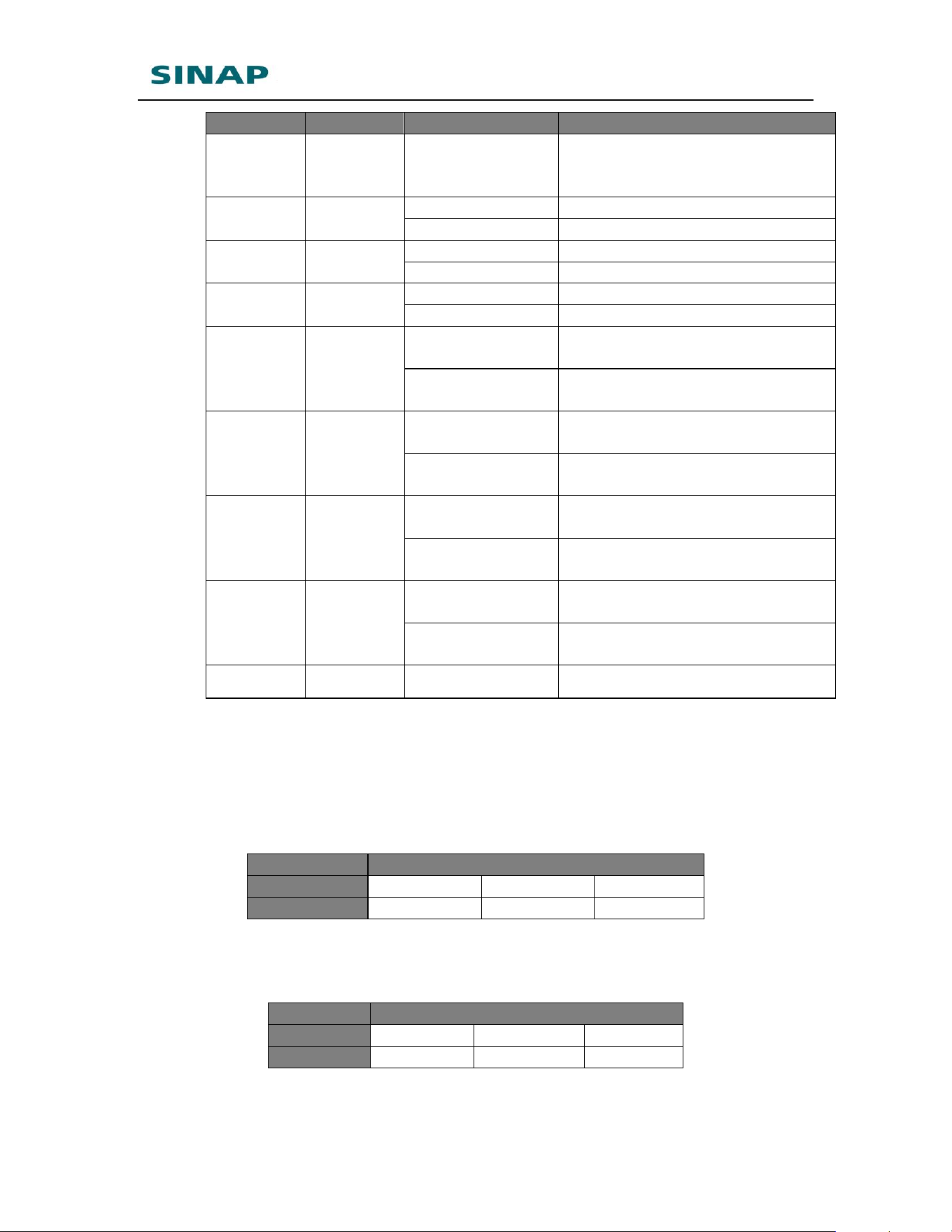
1.6.2 Indicator Light Description
LED
Indicato
Color
Status
Description
SINAPACK 200 User Manual
11
r Light
Signal
lights
Orange
Always light
There are three signal lights.
All lights one means the signal
is strongest.
PWR
Red
Always light
Device is working
Extinguished
Device is not working
WIFI
Green
Always light
WIFI is enabled
Extinguished
WIFI is not enabled
NET
Green
Always light
Connected to Internet
Extinguished
No connection to Internet
SVR1
Green
Always light
DTU has connected to data
center
Extinguished
DTU does not connect to data
center
SVR2
Green
Always light
Connection to mServer is
established.
Extinguished
Connection to mServer is not
established.
232
Green
Flashing
Receive data from RS232
interface
Extinguished
No data received from RS232
interface
485
Green
Flashing
Receive data from RS485
interface
Extinguished
No data received from RS485
interface
ERR
Red
Extinguished
Reserved
Table 1-1 SINAPACK 200 indicator light description
1.6.3 Serial Port Definition
Type
RS-232
Pin
2
3
5
Definition
RXD
TXD
GND
Table 1-2: SINAPACK 200 RS232 serial port
(Standard RS-232 DB9 male port) pin definition
Type
RS-485
Pin
A
B
G
Definition
A
B
GND
Table 1-3: SINAPACK 200 RS485 serial port pin definition
SINAPACK 200 User Manual
12
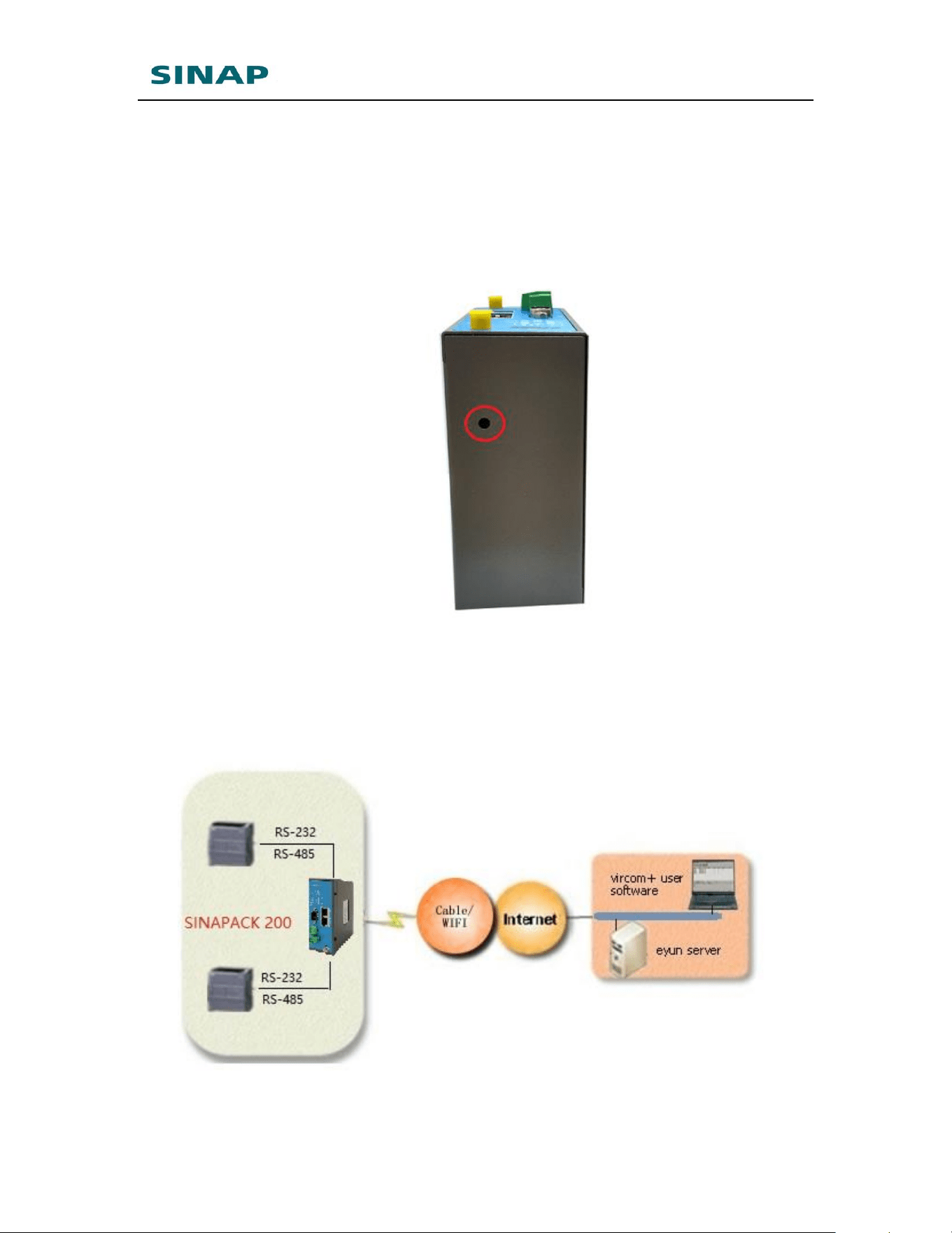
1.6.4 RESET Button
To reset SINAPACK 200 to default, login its configuration web page,
and choose “System tools” -> “Restore set”; Or: press the RESET
button continuously, the signal lights will flash one by one, until all
lights are on, that means the reset is finished.
Figure 1-7: SINAPACK 200 reset button
1.7 Typical Usecases
Figure 1-8: Implement PLC remote monitoring and program update via
SINAPACK 200 User Manual
13
SINAPACK 200’s serial functionality
Figure 1-9: Implement PLC remote monitoring and program update via
SINAPACK 200’s virhub functionality
Figure 1-10: Implement remote control of touchscreen desktop via SINAPACK
200’s agent client functionality and VNC software

SINAPACK 200 User Manual
14
2. Device Configurations
This chapter introduces how to use SINAPACK 200 and related parameters.
1. Configurations
2. Parameters
3. Restore to default
4. Firmware Update
5. Remote Configurations
2.1 Configurations
2.1.1 Preparation
One cross Ethernet cable used to connect SINAPACK 200 with
PC or customer device;
One power supply.
2.1.2 Configuring SINAPACK 200
Connect SINAPACK 200’s LAN(LAN2) with PC via a cross
Ethernet cable;
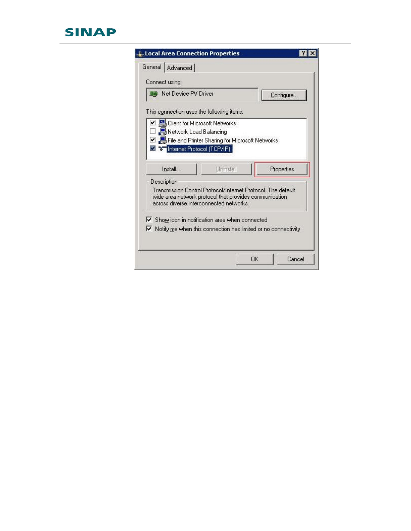
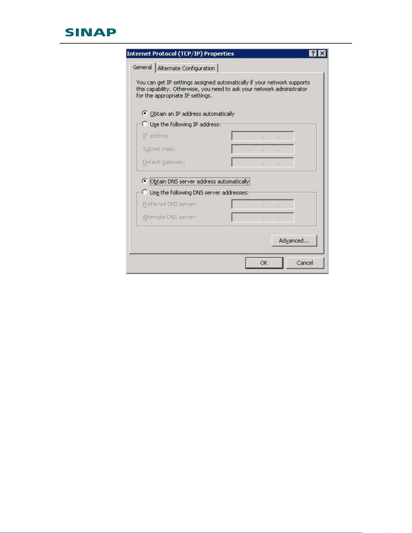
Boot PC, and set IP address as "Automatically obtain IP
address";
SINAPACK 200 User Manual
15
SINAPACK 200 User Manual
16
Figure 2-1: Set IP address as "Automatically obtain IP address"
Open IE browser, input address "http://192.168.10.1" and
press Enter;
Input "root" as username and "1234" as password, then press
Enter to login web configuration interface and configure the
device.
Figure 2-2: Login router configuration interface
It is clear to see each configuration item in the router
configuration interface. To change some parameter, click it,
modify and then save it, then reboot the router.
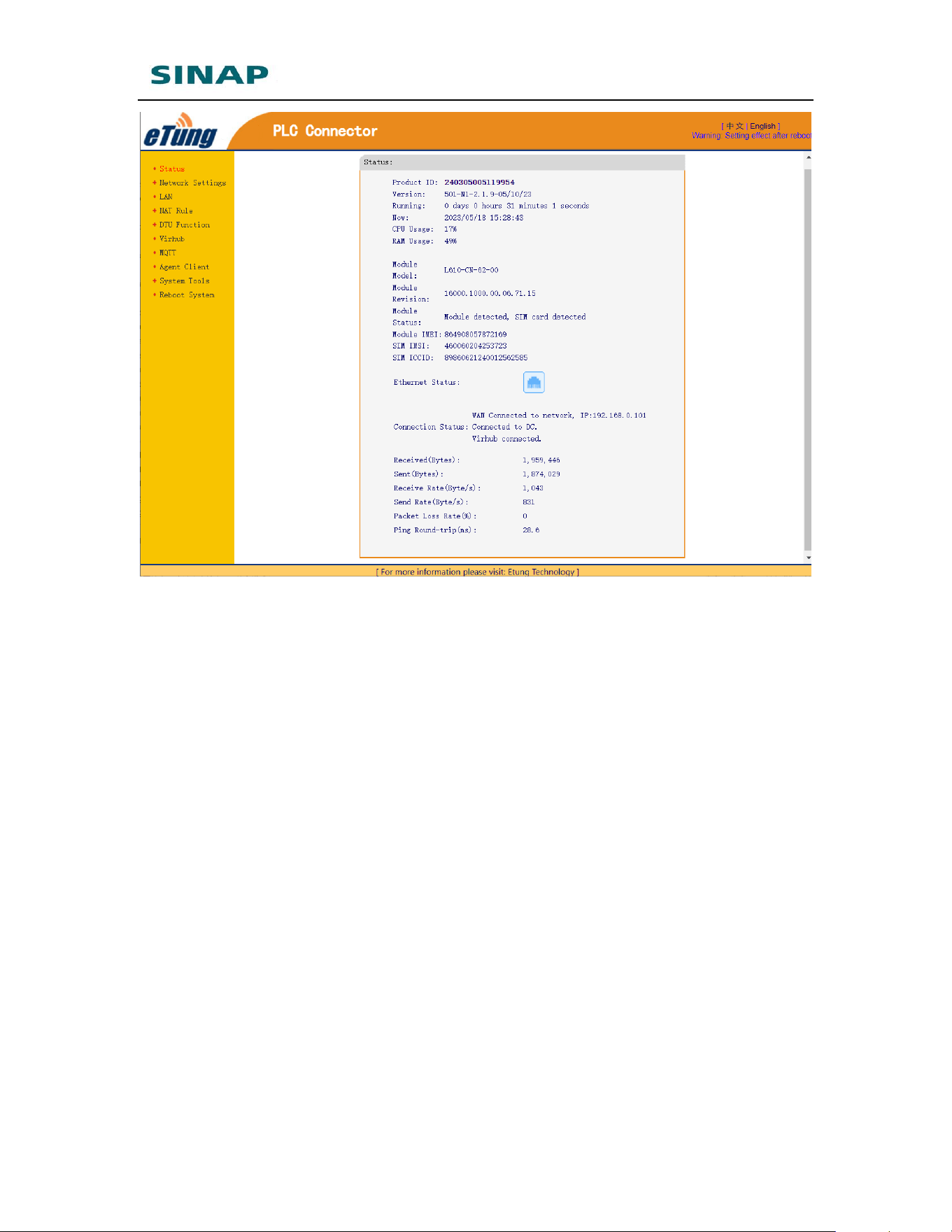
Below shows SINAPACK 200’s current status, including: product
ID, version, running time, current time, CPU usage, memory
usage, status, model and model manufacturer, WAN/LAN
connection status, current status, network, network speed, and
signal, etc.
SINAPACK 200 User Manual
17
Figure 2-3: Current Status
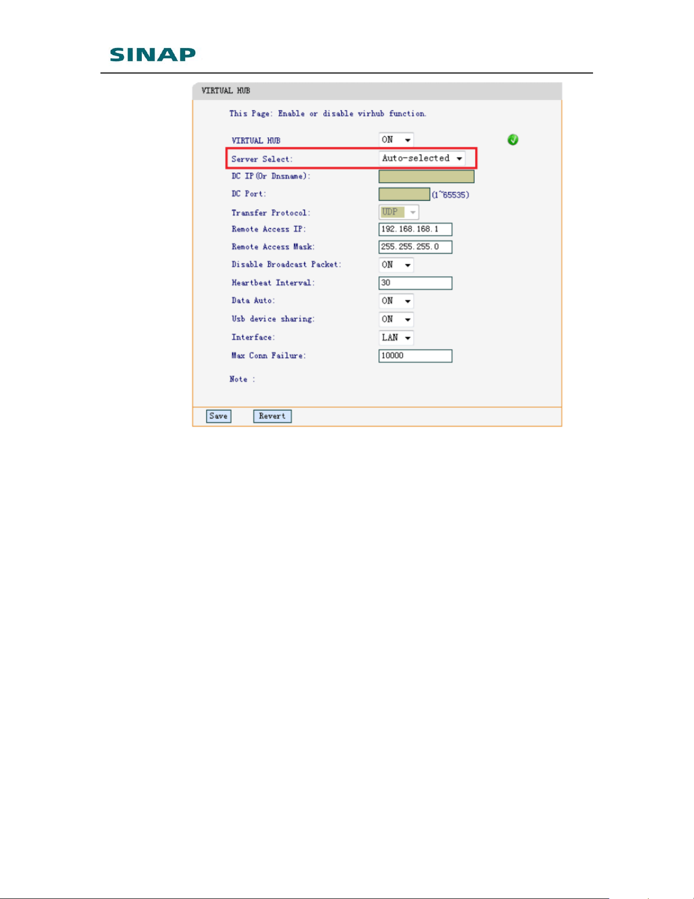
To use virhub functionality, click “Virhub”, virhub functionality is
enabled by default; server is set to auto-selected by default that
means SINAPACK 200 will automatically choose the server that
is near it and has lowest network delay.
SINAPACK 200 User Manual
18
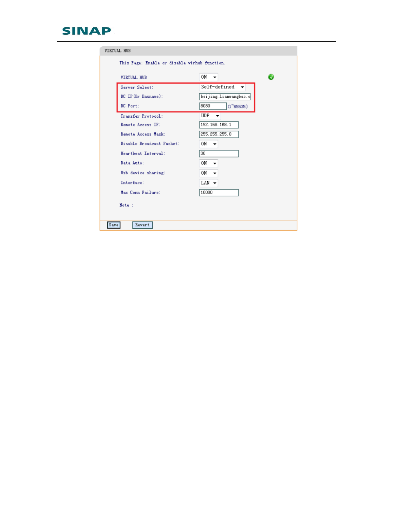
Server can also be set manually, as shown in the figure below,
Server is set to “Self-defined”, and then input server domain/IP
and port accordingly.
SINAPACK 200 User Manual
19
Figure 2-4: Configure virhub functionality
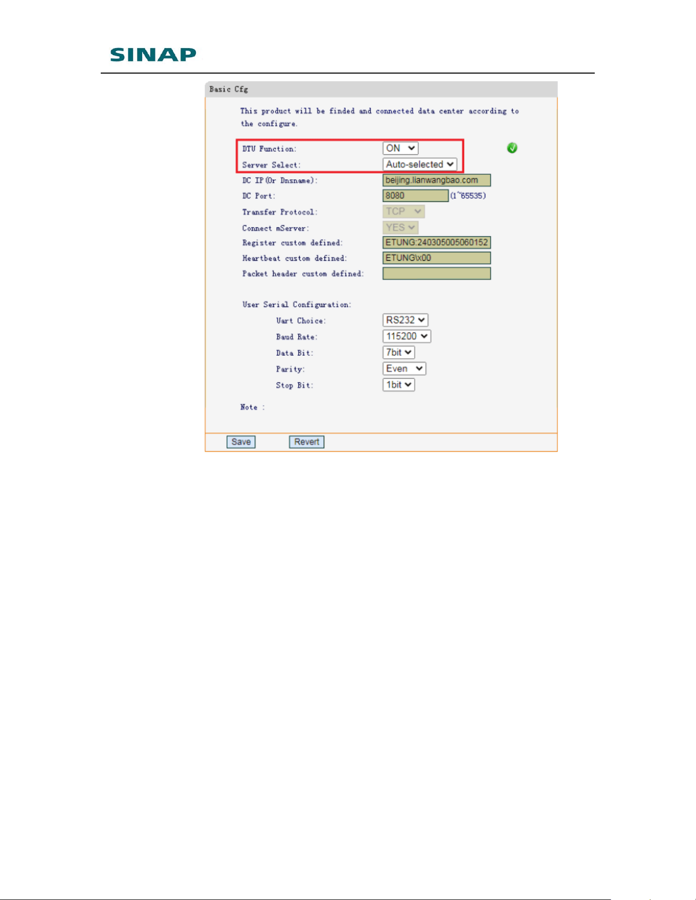
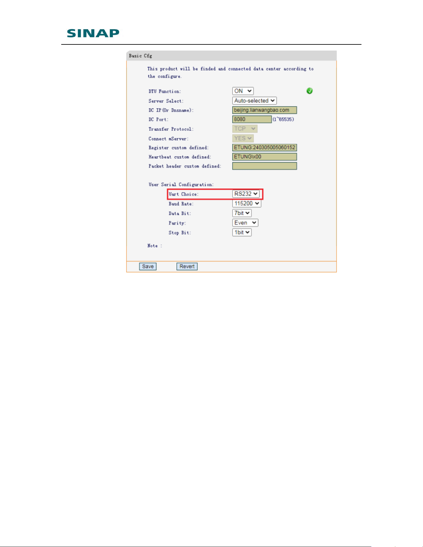
To use DTU functionality, click “DTU Function” -> “Basic Cfg”. DTU
function is enabled by default; server is set to auto-selected by
default that means SINAPACK 200 will automatically choose the
server that is near it and has lowest network delay.
SINAPACK 200 User Manual
20
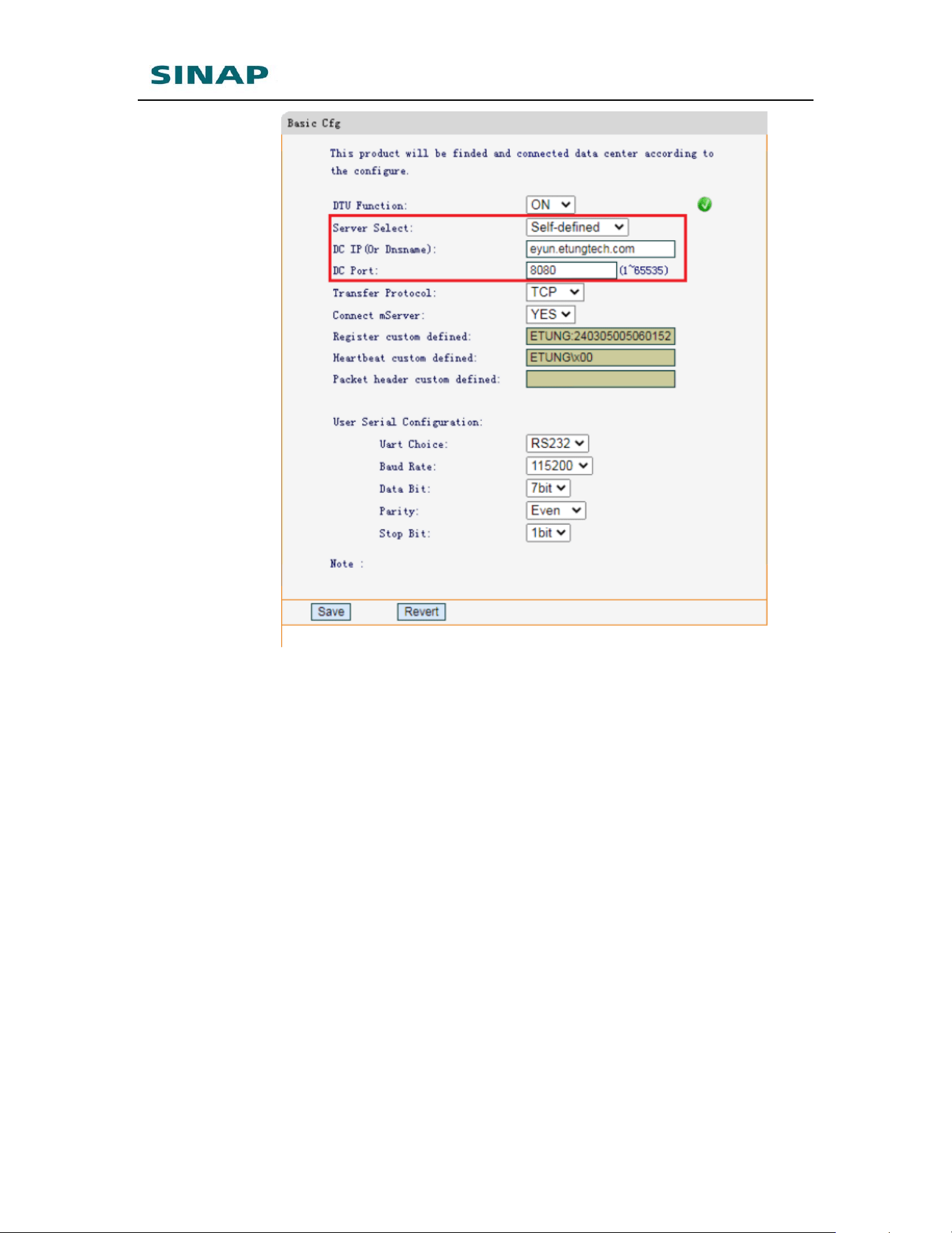
Server can also be set manually, as shown in the figure below,
Server is set to “Self-defined”, and then input server domain/IP and
port accordingly.
SINAPACK 200 User Manual
21
Figure 2-5: Configure DTU functionality
SINAPACK 200 has one RS232 and one RS485 serial port, choose
either serial port to use in “UART Choice”:
SINAPACK 200 User Manual
22
Figure 2-6: Choose serial port
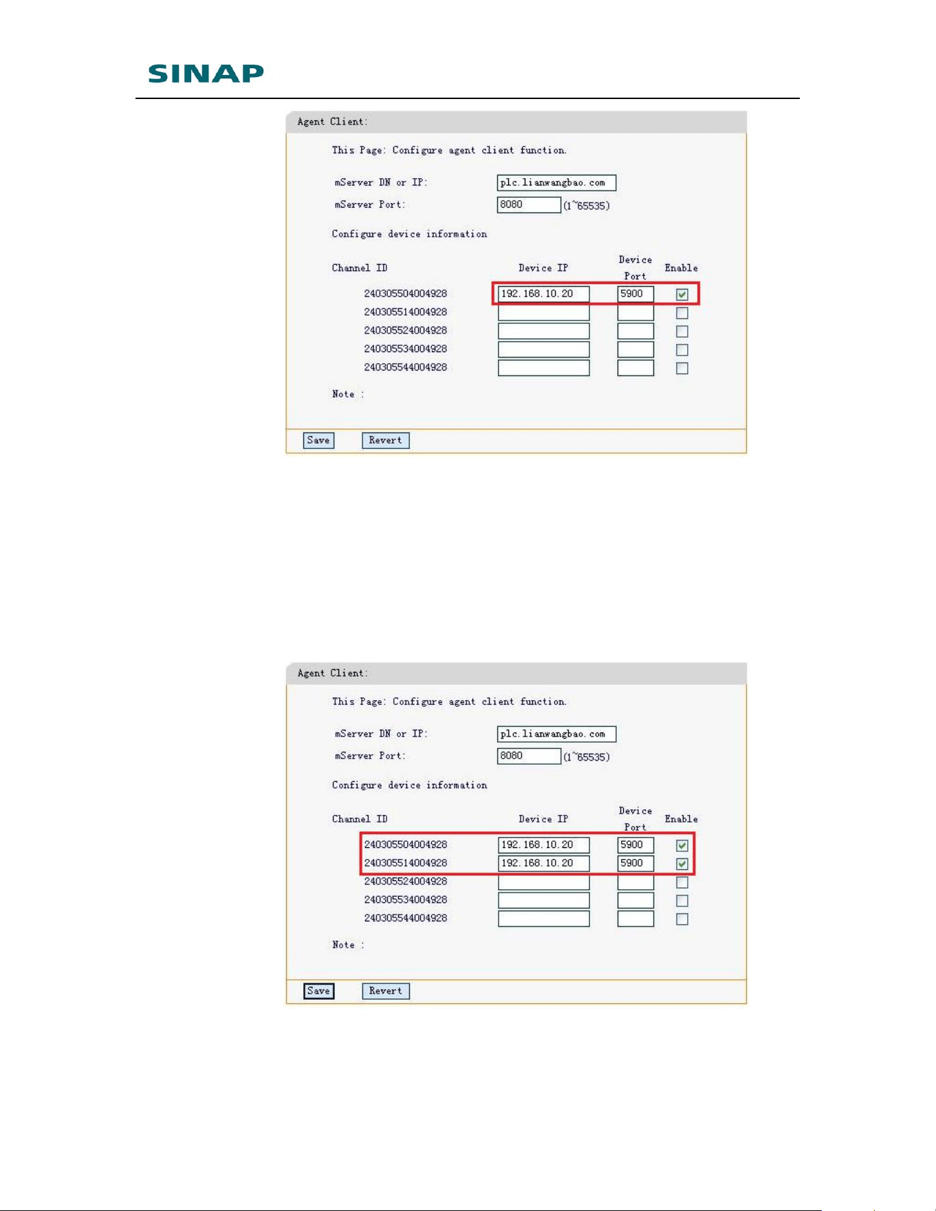
In case that SINAPACK 200 is used together with VNC software to
perform remote access, agent client functionality is used. To
configure agent client functionality, click “Agent Client”, set
mServer (plc.SINAPACK 200.com) DN and port (8080), the default
values are eTung mServer DN and port, normally keep the default
values, unless users build its own mServer. Then configure device
information, set device IP (for example, 192.168.10.20) and port
(for example, 5900), and tick “Enable”, then click Save and reboot
SINAPACK 200.
SINAPACK 200 User Manual
23
Figure 2-7: Configure agent client functionality
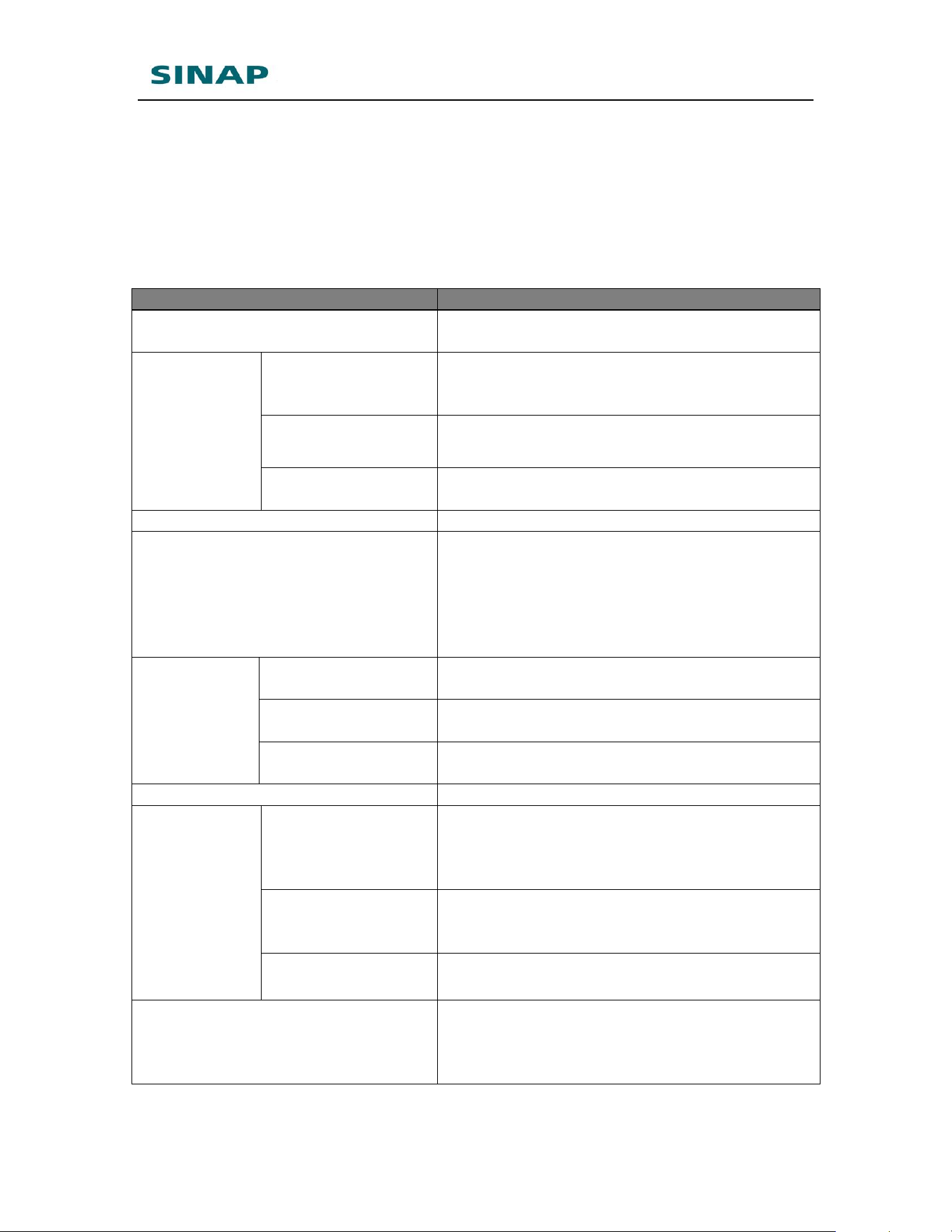
It is possible to configure multiple lines in agent client configuration,
each line corresponds to a channel, and at most 5 channels are
supported. Each channel has a 15-byte channel ID. The channel ID
is derived from SINAPACK 200’s IMEI. For example, SINAPACK
200’s IMEI is 240305001234567, then the agent clients’ channel ID
is 2403055X1234567, and X can be 0~4, to represent one of the
five channels. For example, set two channels as shown in the figure
below:
Figure 2-8: Configure multiple channels in agent client functionality
SINAPACK 200 User Manual
24
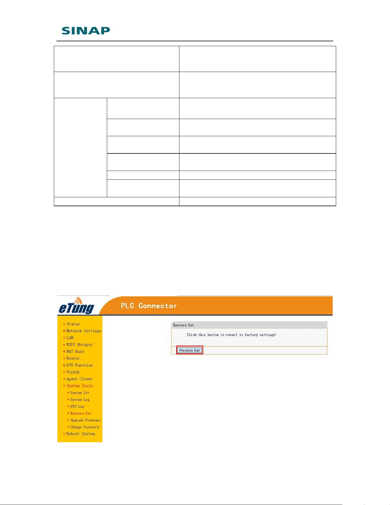
2.2 Configuration Parameters
Each configuration menu has multiple parameters, and some of them
have sub-menus. Details are described below.
Configuration Menu Item
Description
Current status
Show device information, connection and
data transfer status.
Network
Settings
Network Select
Configure to use cable network (WAN) or
WIFI, set ICMP host, and whether to allow
external access.
WAN
Configure WAN interface, WAN is enabled
by default.
WIFI client
Configure WIFI parameters. Once WIFI is
enabled, WAN will be disabled.
LAN
Set inner IP and DHCP
WIFI Hotspot
Configure WIFI hotspot parameters. WIFI
hotspot and WIFI client cannot be used at
the same time, to enable WIFI hotspot
function, please disable WIFI client if it is
enabled: set network to WAN in network
settings.
Forwarding
rules
NAT
Whether the device connected with router
can access internet via NAT.
Port forwarding
Use pre-defined port to forward data from
internet to some inner IP's dedicated port.
DMZ host
Forward data from internet directly to
some inner IP.
Routing
Forward data to a pre-defined inner IP
DTU
Function
Simple Cfg
Set data center address and serial port
parameters, by default server is set to
auto-selected, and there is no need to
change.
Advanced Cfg
Set advanced parameters, for example,
frame size for data transmission, and
timeout for data received from serial port.
Link Management
Set heart beat parameters, normally with
default values
Virhub
Set server address for Virhub function,
“Auto-selected” by default that means it
will automatically choose the server that is
near it and has lowest network delay.
SINAPACK 200 User Manual
25
MQTT
Set MQTT version. There are two versions:
Standard and General, and General by
default.
Agent Client
Configure agent client. Configure mServer
domain and port, the master device’s IP ad
port. Allow at most 5 agent clients.
System tools
System settings
Set router's communication parameters,
normally with default values
Show system log
Show router's connection and
communication logs
Show DTU log
Show router's data transfer logs with DTU
function
Restore to default
Restore to initial default settings with one
key
Update firmware
Update router's firmware
Change password
Change password logging router(1234 by
default)
Reboot
Reboot router
Table 2-1: Details of configuration parameters
2.3 Restore to Default
According to the description of "Configuring SINAPACK 200", after
entering SINAPACK 200 configuration interface, select "System Tools"
and then "Restore Set".
SINAPACK 200 User Manual
26
Figure 2-9: Restore to default
Or: press the RESET button continuously to reset it to default.
2.4 Firmware Update
Ask eTung for firmware to update. The firmware (*.img) can be
uploaded from local disk, or downloaded from a server from
Internet.
According to the description of "Configuring SINAPACK 200", connect
SINAPACK 200 with PC via a cross Ethernet cable, open browser, input
http://192.168.10.1 as URL, input username and password (by default
username is root and password is 1234), and login router configuration
webpage.
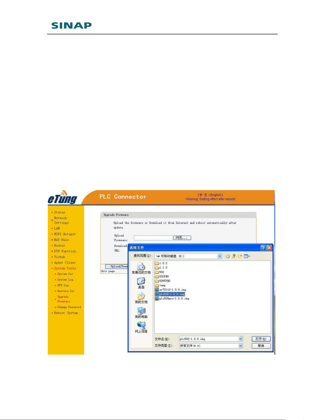
Select "System tools" and then "Upgrade Firmware";
If the firmware is on the local disk, click "Browse", select the file
(.img) to update, and click "Open", then click "Upload/Download":
Figure 2-10: Upgrade firmware
SINAPACK 200 User Manual
27
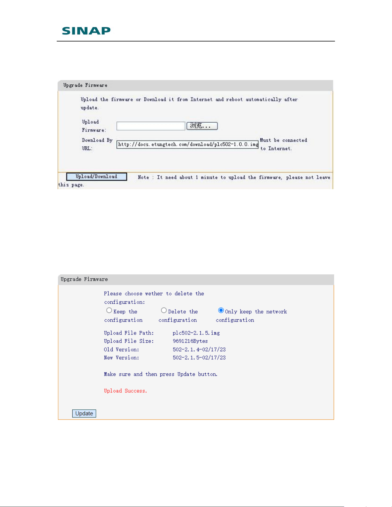
If the firmware can be downloaded from a server, input download
URL (please ask eTung technical support for the URL), and click
“Upload/Download”:
Figure 2-11: Input URL and download firmware
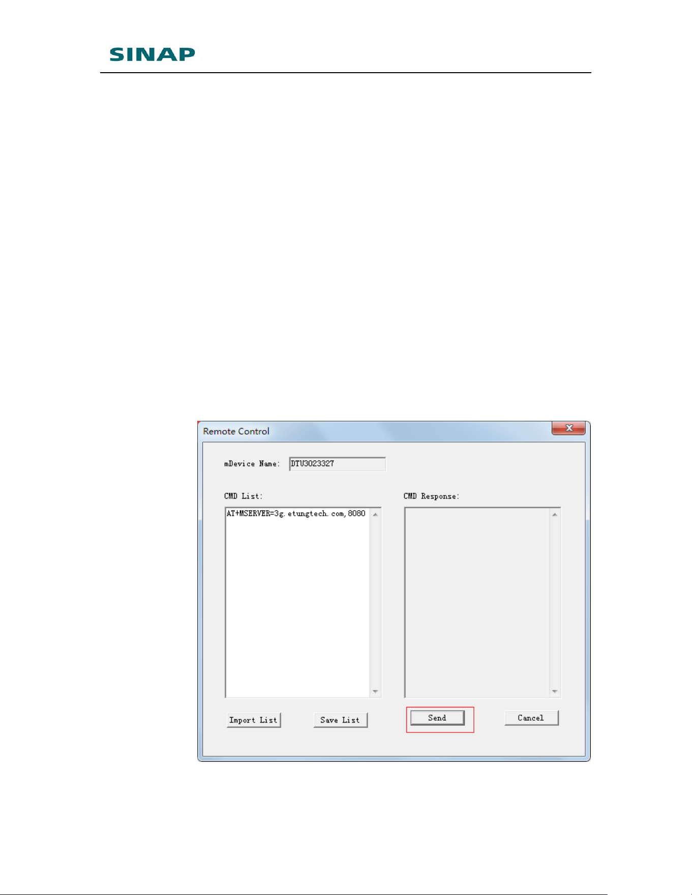
Wait for a moment, until "Update" is shown, choose "Delete the
configuration" (delete all configurations), or “Only keep the
network configuration” (delete all configurations except network
configuration), then click “Update”. It will prompt the file system
has been updated, the original settings is clear, and the system is
rebooting. Wait a moment and then refresh the webpage to see the
configuration page again.
Figure 2-12: Choose delete the configuration or keep network configuration
SINAPACK 200 User Manual
28
2.5 Remote Configurations
Remote AT commands can be used on SINAPACK 200 to modify
configuration parameters remotely. Details are described below:
NOTE: this can be used only when enabling DTU function or virhub
function, and SINAPACK 200 is shown online in mServer.
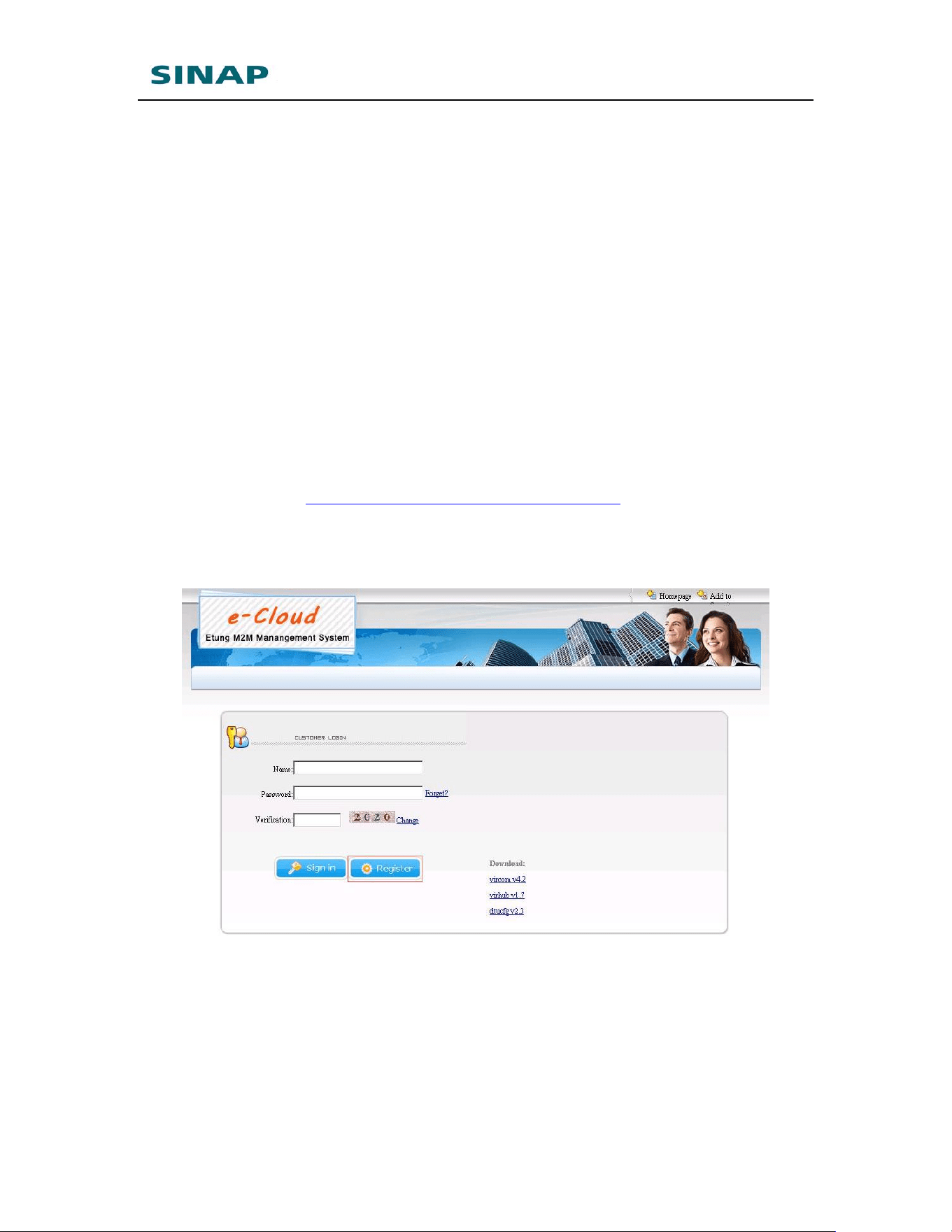
Choose the router in mServer’s console, right-click it and choose
“Remote Control”, in the popped-up dialog, input AT commands in
“CMD List” on the left side.
For example, input the following command to change the data
center’s address and port:
AT+MSERVER=3g.etungtech.com,8080
Click “Send” afterwards, and if successful, a “OK” will show in
“CMD Response” on the right side. Then SINAPACK 200 will be
offline from the original mServer, and connect to the new data center
and port.
Figure 2-12: Transfer Terminal remotely

SINAPACK 200 User Manual
29
Below are remote AT commands that are supported on SINAPACK 200
Ethernet channels.
1) AT+MSERVER=addr, port
Change data center address and port, with reply OK or ERROR.
addr: data center address, either IP address or domain
port: data center port
2) AT+CSQ
Query signal strength and network mode, with the following
reply:
OK:sig_quality,net_mode
sig_quality: 0-31, bigger value means better signal quality
net_mode:
3) AT+REBOOT
Reboot the router, with reply OK.
4) AT+HBI?
Query heart beat interval (unit: second), with reply OK.
5) AT+HBI=interval
Set heart beat interval (unit: second), with reply OK.
6) AT+SMSPING=PHONE_NUM
Ask the router to send an SMS to PHONE_NUM, and the
content is the router’s IMEI number, with reply OK.
7) AT+SMSZHUANFA=txt,info_src,dest
Ask the router to send an SMS to info_src first with content
“txt” (only in English characters and digits), and then forward
the reply to dest. dest can be omitted, and if then the reply will
be forwarded to the mobile that sends this AT command. If the
reply SMS has more than one message, the router will forward
the messages one by one.
For example: AT+SMSZHUANFA=CXLL,10086,13801234567,
means to send an SMS to 10086 to query traffic and then
forward the reply to 13801234567.
8) AT+RDEBUG&ENABLED=0/1
Enable/Disable remote debugging, with reply OK.
9) AT+SIMID
Query SIM IMSI and CCID.
10) AT+CELLID
Query base station’s location code and cell code.
11) AT+OPER
Query operator information.

SINAPACK 200 User Manual
30
12) AT+NETMODE
Query current network in use, with reply:
+NETMODE: WAN/WIFI/MOBILE\r
OK
13) AT+IFSTATUS
Query data interfaces’ status, with reply:
+IFSTATUS: SERIAL(0/1,0/1), LAN(0/1,0/1)\r
OK
Bracket SERIAL(0/1,0/1) shows RS232 and RS485 data
interfaces’ status: 1 means data are received from the serial
interface, otherwise 0. Bracket LAN(0/1,0/1) shows LANs’
status: 1 means cable line is plugged, otherwise 0.
SINAPACK 200 User Manual
31
Appendix 1: Use SINAPACK 200
Virhub Functionality to Implement
PLC Program Remote Update
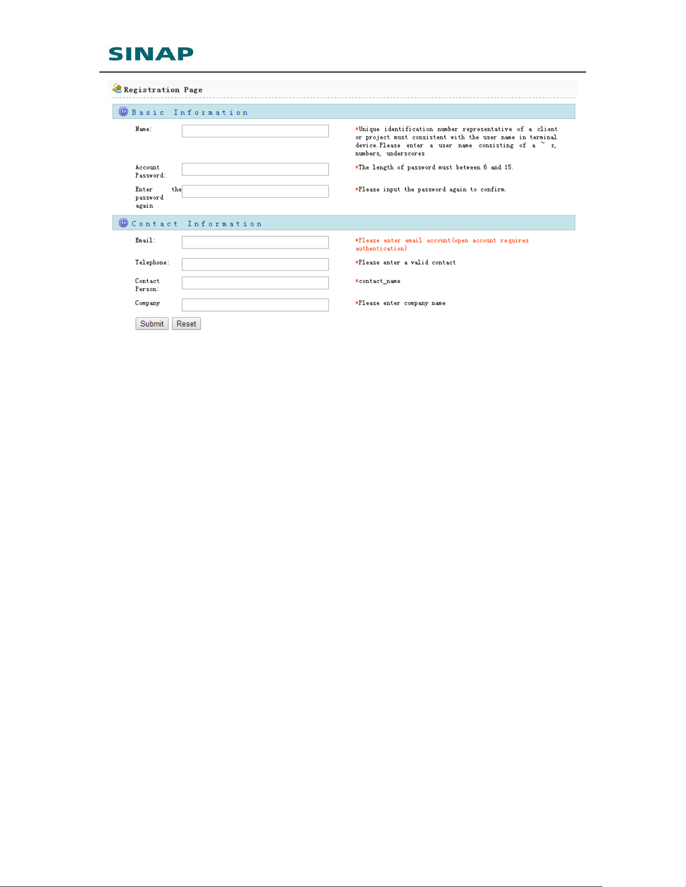
1. Apply eYun account
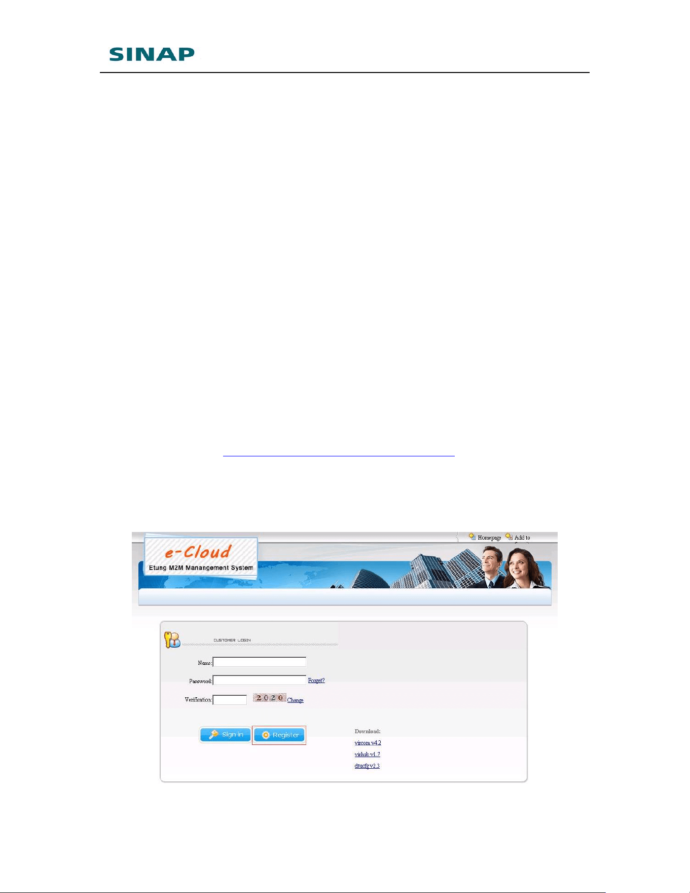
Access website http://wangkoutong.lianwangbao.com, press “Register”, and
input registration information. Pay attention that the password should not
be too simple. Input a correct email address, then after submit the system
will automatically send a web link to the mailbox, just click the link to
enable the account.
Figure Appendix 1-1: Apply eYun account
SINAPACK 200 User Manual
32
Figure Appendix 1-2: Input registration information
2. Configure SINAPACK 200
Connect SINAPACK 200 with PC via Ethernet cross cable, and the IP
address in PC is set to obtain automatically;
Open browser and input URL: 192.168.10.1;
Input username: root, and password: 1234 to login;
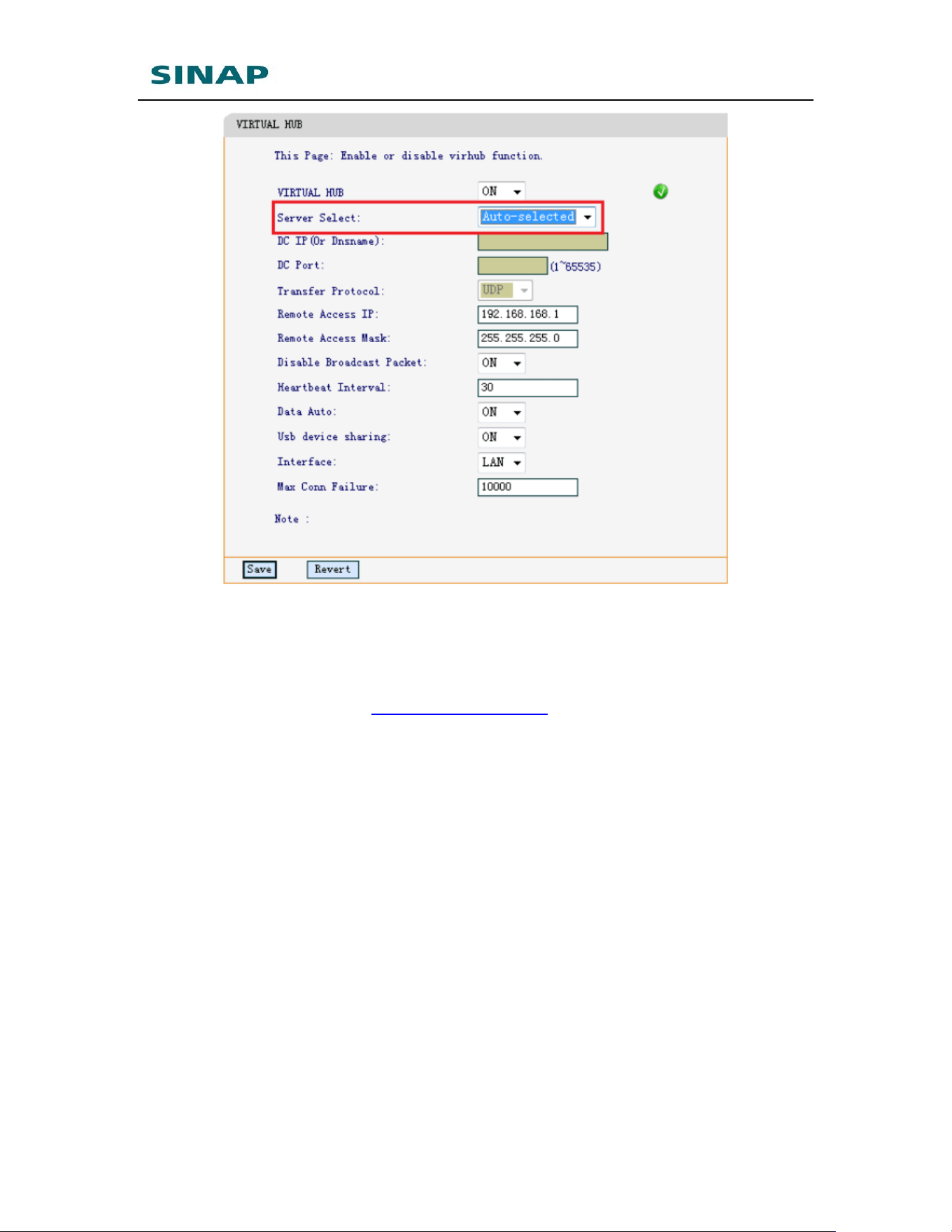
Choose “Virhub” in the menu list, enable virhub, server is set to
auto-selected by default that means SINAPACK 200 will automatically
choose the server that is near it and has lowest network delay.
Choose “Reboot System” in the menu list, and reboot SINAPACK 200.
SINAPACK 200 User Manual
33
Figure Appendix 1-3: Configure SINAPACK 200’s virhub functionality
3. Configure Virhub software
Open and run Virhub installation package from eTung’s CD, or downloaded
from eTung’s website: www.etungtech.com: Downloads->Software. Run
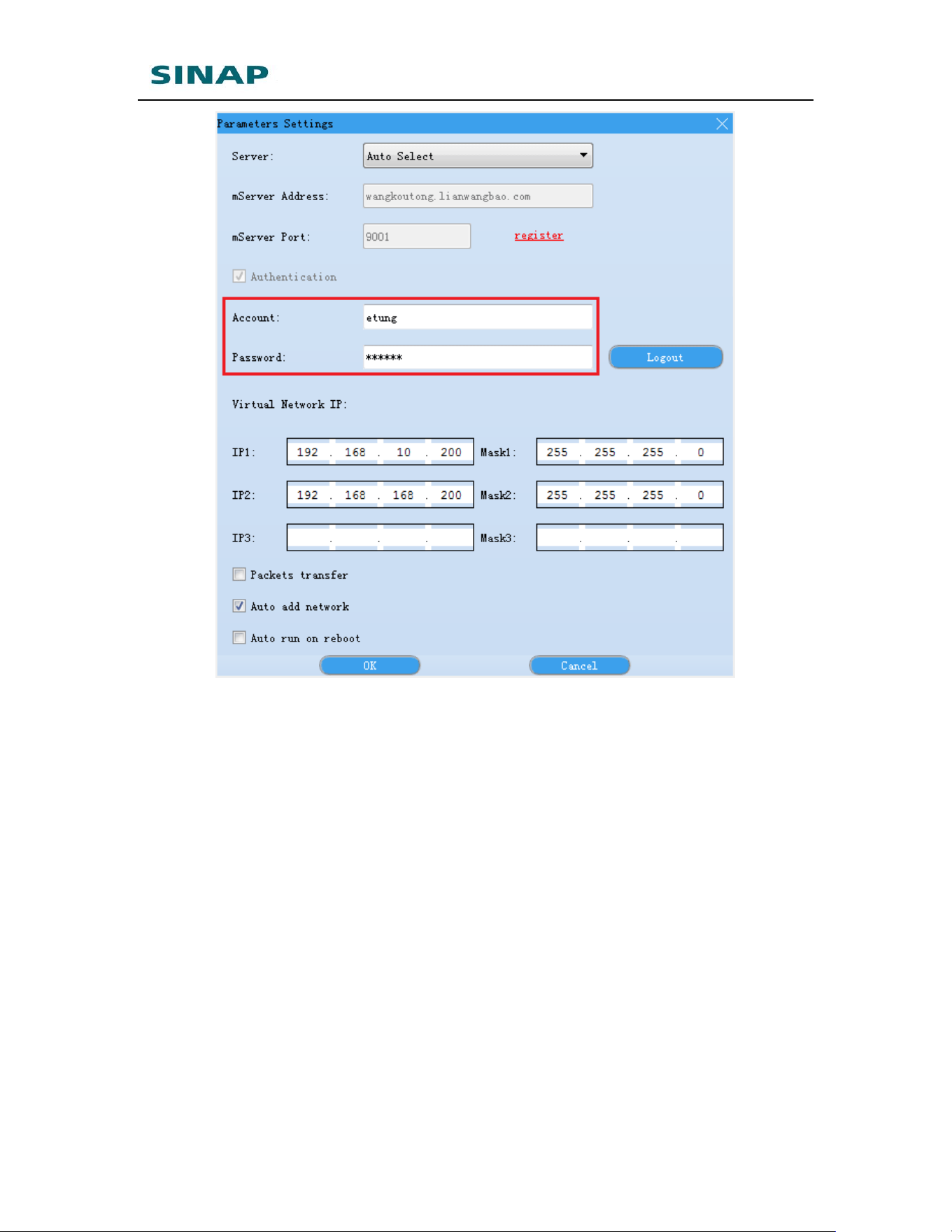
Virhub and click "Settings", server is set to “Auto Select” by default, input
the username and password applied before.
SINAPACK 200 User Manual
34
Figure Appendix 1-4: Login Virhub
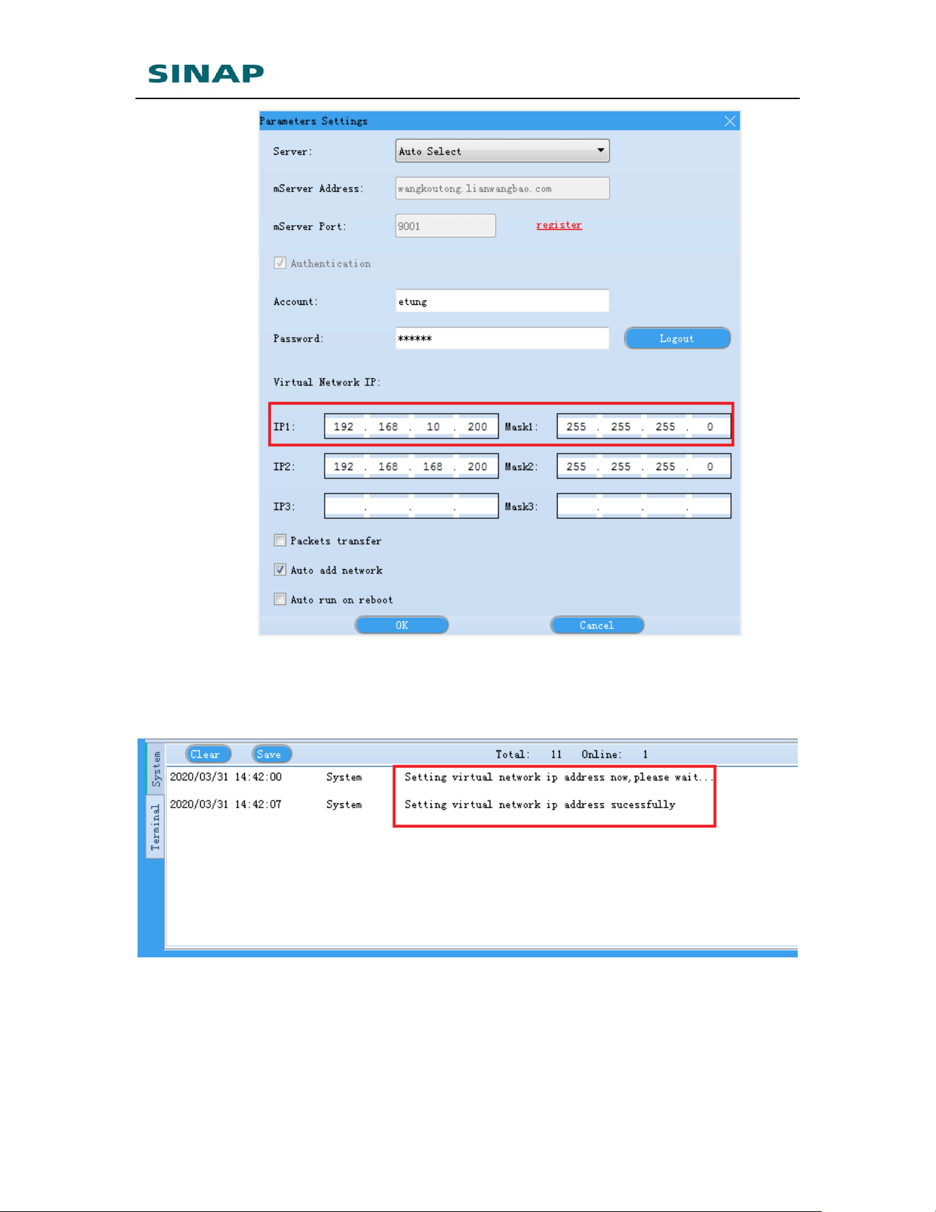
1) Configure virtual network adapter’s IP address: in the “Settings” dialog, we
can set virtual net adapter’s IP address in “Virtual Network IP”. Set IP1 to
be in the same IP range as PLC’s IP that connects to SINAPACK 200, for
example, PLC’s IP is 192.168.10.20, and then set IP1 to 192.168.10.200.
The virtual net adapter is used to build a virtual LAN with PLC. In Virhub IP1,
IP2 and IP3 can be set on the virtual net adapter. If all PLCs are in the same
IP range, then just set IP1.
SINAPACK 200 User Manual
35
Figure Appendix 1-5: Configure virtual network adapter’s IP address
Press “OK” after configuration, in the system info area, there will be a
prompt “Setting virtual network ip address successfully”, then the
software has set the IP address to the virtual net adapter
Figure Appendix 1-6: Succeed to set IP address of Virtual network adapter
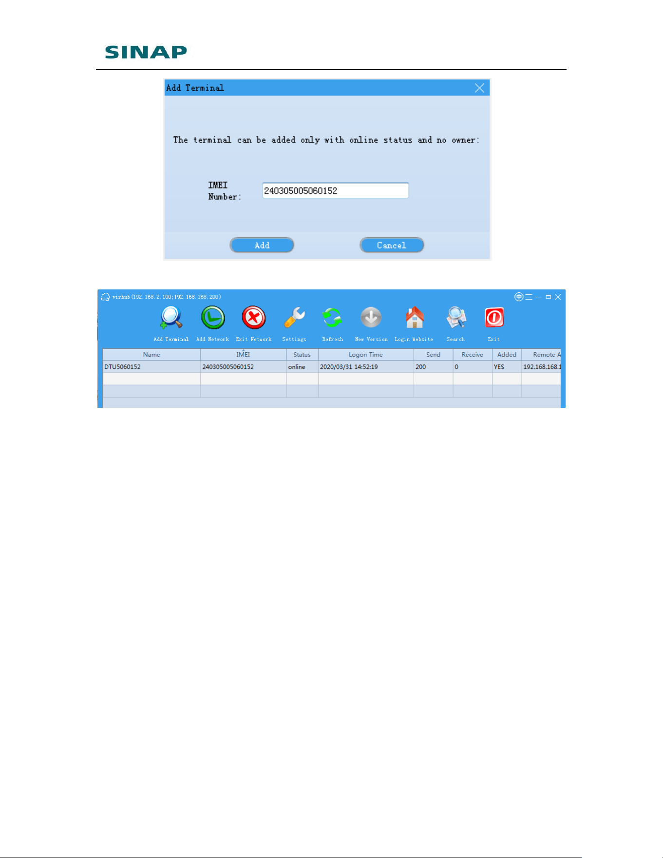
2) Add device: in Virhub software add SINAPACK 200 to the user account:
press “Add Terminal”, and input the IMEI number of SINAPACK 200.
SINAPACK 200 User Manual
36
Figure Appendix 1-7: Add device
Figure Appendix 1-8: Succeed to add device
If add device fails, please first make sure if the SVR2 led light is on, that
means SINAPACK 200has connected to eYun platform. If SINAPACK
200 does not connect to eYun platform, add device will fail.
3) Then Virhub configuration is complete, check if the communication
between host pc and PLC is OK. Open a cmd window, input command:
ping 192.168.*.* (PLC’s IP address), If there are responses, that
means the communication is OK, then use PLC programming software
to update program. And if there is no response for a long time, please
contact eTung technical support.
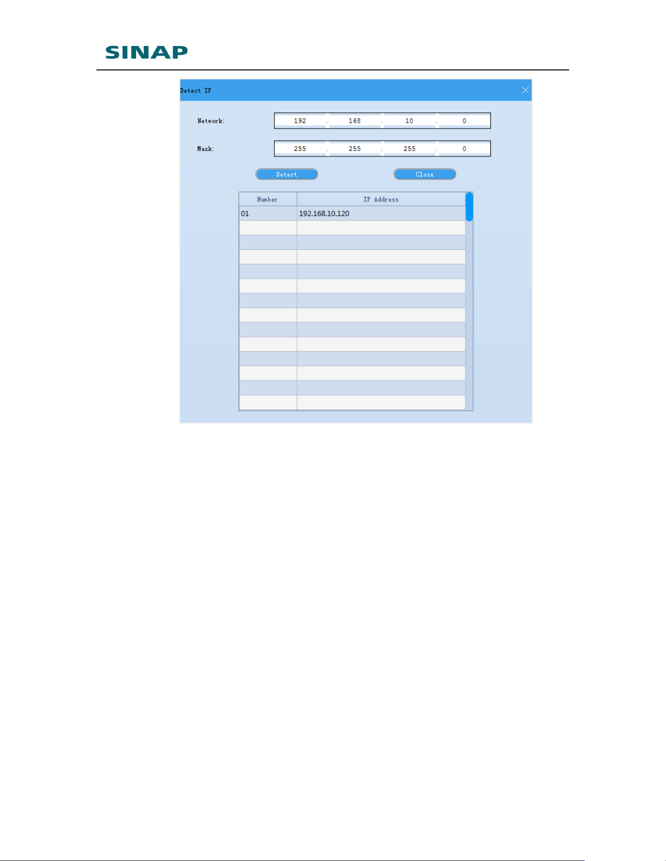
4) Detect IP address of devices via Virhub
In order that PC running Virhub can communicate with devices at the
far end that connect to SINAPACK 200, the devices’ IP must be known
beforehand. Virhub’s “Detect IP” functionality can automatically detect
the devices’ IP.
In Virhub’s interface, right-click the terminal and choose “Detect IP”,
offer the device IP’s subnet area, and then click “Detect IP”; and after a
while, the IPs detected will be shown in the list, as shown in the figure
below:
SINAPACK 200 User Manual
37
Figure Appendix 1-9: Detect device’s IP address
Attention:
1) The terminal must be online to use this functionality;
2) Virhub version must be V9.0 or higher.
4. Access SINAPACK 200 remotely via Virhub
SINAPACK 200 can be accessed remotely via Virhub. Normally, SINAPACK
200 accesses Internet via Cable/WIFI network, and gets an inner IP
address, and it cannot be accessed from the internet via this inner IP.
eTung’s Virhub solution can solve the problem. First, enable Virhub function
on SINAPACK 200, and set a remote access IP; the remote access IP is
dedicated to access SINAPACK 200 remotely when Virhub is enabled on it.
Then run Virhub software on the far-end PC, and configure an IP address on
the Virtual Network adapter; this IP must be in the same range as the
remote access IP on SINAPACK 200. This way, we can access the router
remotely on the far-end PC via the remote access IP, to perform
configuration, system monitoring, etc. Below are the details about the
configuration procedure.
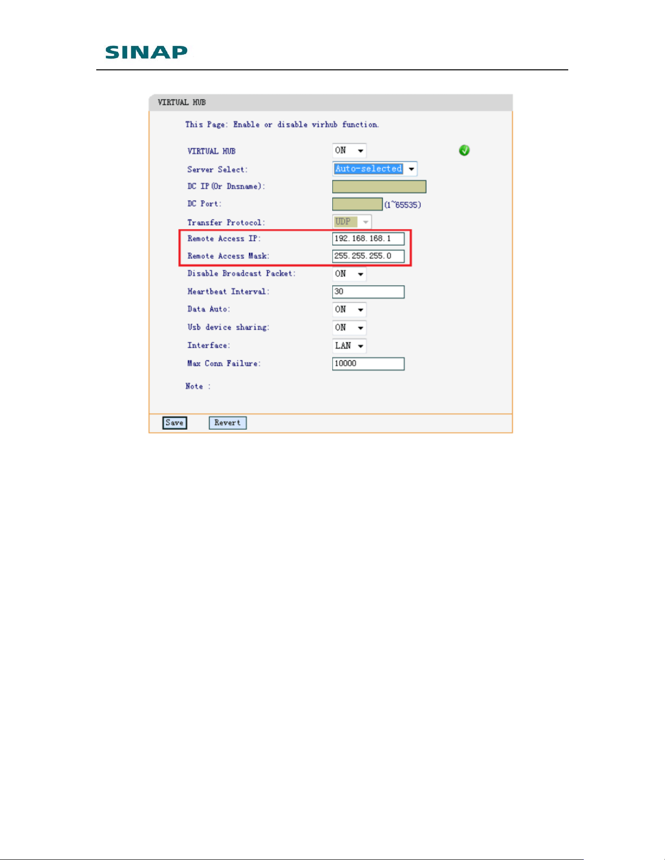
1) Configure the router’s remote access IP
According to “2.1 Configuring SINAPACK 200”, go to the router’s Virhub
configuration, enable Virhub and configure username, then there are
two parameters: “Remote Access IP” and “Remote Access Mask”, with
default values: 192.168.168.1 and 255.255.255.0.
SINAPACK 200 User Manual
38
Figure Appendix 1-10: Configure SINAPACK 200r’s remote access IP
Normally set the two parameters with default values, and they can also
be changed on demand. Press “Save” after configuration, and then
reboot the router. These two parameters can also be changed/checked
via remote AT commands, please refer “2.5 Remote Configurations”.
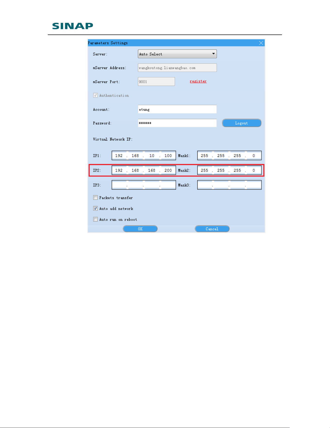
2) Configure the Virtual Network adapter’s IP address to access SINAPACK
200 remotely
Run Virhub software, click button “Configure”, and on the popped up
“Settings” dialog, set the Virtual Network adapter’s IP address in
“Virtual Network IP” part. IP2 is the IP address set on the Virtual
Network adapter to access SINAPACK 200 remotely via Virhub, and this
IP must be in the same range as the “Remote Access IP”
(192.168.168.1 by default) set on SINAPACK 200 in step 1), for
example, 192.168.168.*.
SINAPACK 200 User Manual
39
Figure Appendix 1-11: Configure the Virtual Network adapter’s IP
address to access SINAPACK 200 remotely
Click “OK” after configuration is complete, the software will then set the
IP address on the Virtual Network adapter.
3) Access SINAPACK 200 remotely
Open browser, and input SINAPACK 200’s remote access IP
(192.168.168.1 by default), and then SINAPACK 200’s web
configuration page shows.
Figure Appendix 1-12: Access SINAPACK 200’s Web configuration page
remotely
Then we can login the web page to change SINAPACK 200’s parameters
remotely, just as SINAPACK 200 is directly connected locally.
Attention: When host pc accesses SINAPACK 200’s webpage remotely via
virhub, it reaches SINAPACK 200 with its remote access IP address,
192.168.168.1 by default. If the default remote access IP address is used, in
order to make it work, make sure that only one device is mapped at one time in
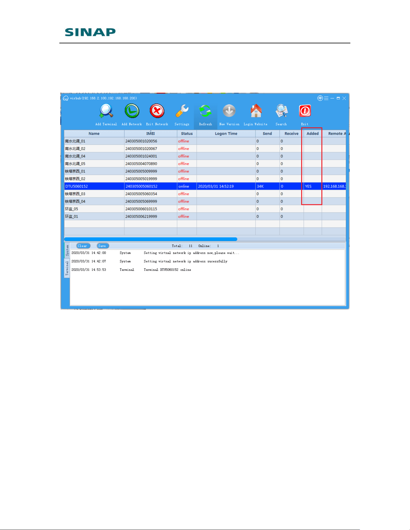
SINAPACK 200 User Manual
40
virhub, as shown in the figure below, in column “Added”, there should be only
one device that is marked as YES, i.e. the device that need to be accessed is
added to the virtual network, and disconnect all the other devices from the
virtual network (click the device, and then click “Exit Network”).
Figure Appendix 1-13: Map device in virhub
SINAPACK 200 User Manual
41
Appendix 2: Use SINAPACK 200
Serial Functionality to Implement
PLC Program Remote Update
SINAPACK 200 has two user serial ports, so it can connect with PLCs that have
serial ports, and perform remote program download and transparent data
transmission. eYun platform and Vircom functionality make it easier to
implement remote access of PLCs that have serial port. Below we will illustrate
the implementation in detail.
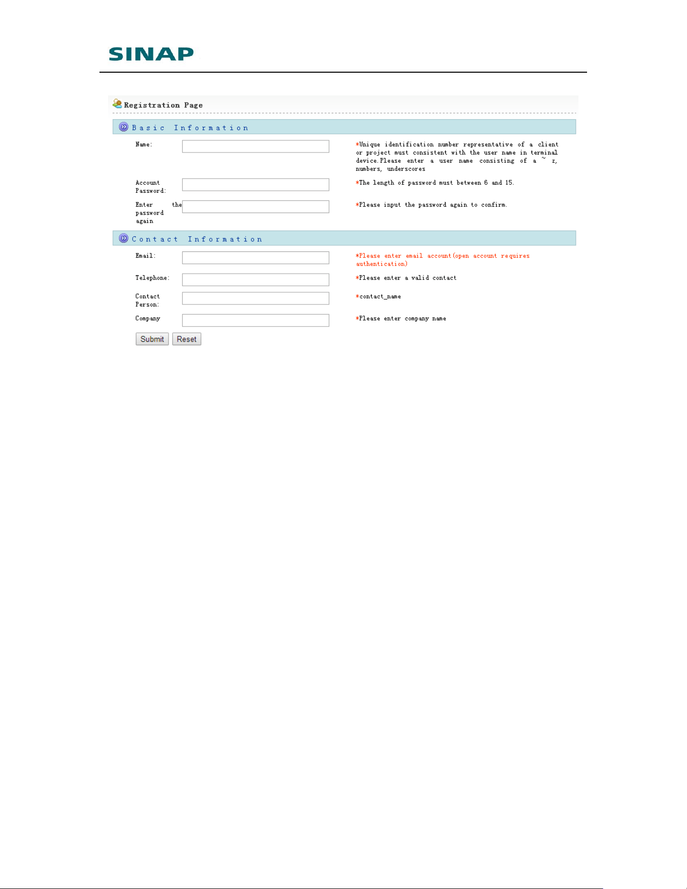
1. Apply SINAPACK 200 eYun account
Access website http://chuankoutong.lianwangbao.com, press “Register”,
and input registration information. Pay attention that the password should
not be too simple. Input a correct email address, then after submit the
system will automatically send a web link to the mailbox, just click the link
to enable the account.
Figure Appendix 2-1: Apply eYun account
SINAPACK 200 User Manual
42
Figure Appendix 2-2: Input registration information
2. Configure SINAPACK 200
Connect SINAPACK 200 with PC via Ethernet cross cable,
the IP address in PC is set to obtain automatically;
Open browser and input URL: 192.168.10.1;
Input username: root, and password: 1234 to login;
Choose “DTU Function”;
DTU function is enabled by default, server is set to auto-selected by
default that means SINAPACK 200 will automatically choose the server
that is near it and has lowest network delay.
Choose serial type (RS232 or RS485) based on PLC serial port type, and
set serial port parameters (baud rate, data bits, stop bits and parity);
Click “Save” and choose “Reboot System” in the menu list, and reboot
SINAPACK 200.
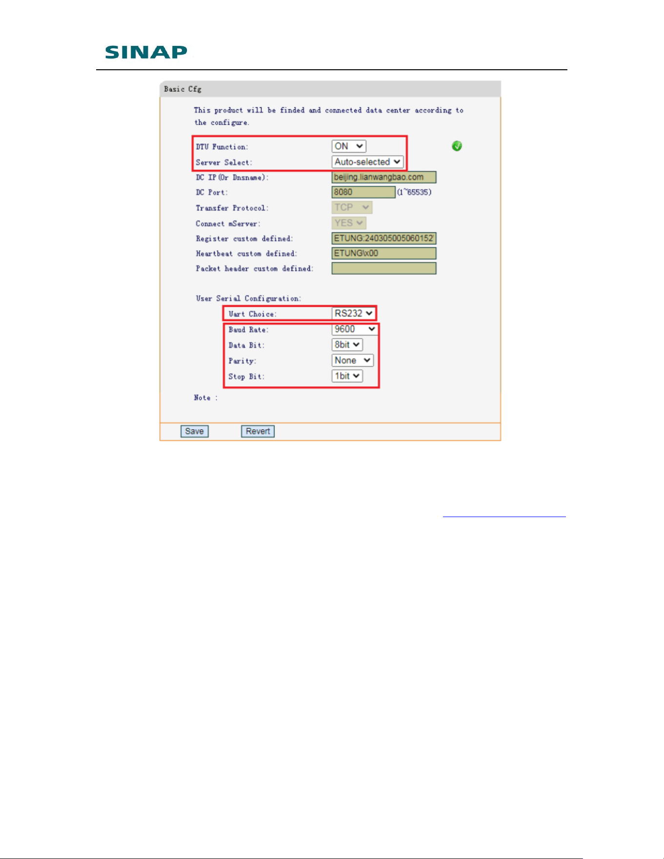
SINAPACK 200 User Manual
43
Figure Appendix 2-3: Configure SINAPACK 200’s serial functionality
3. Configure Vircom software
Find Vircom installation package from eTung website: www.etungtech.com:
Downloads->Software, then download and install Vircom.
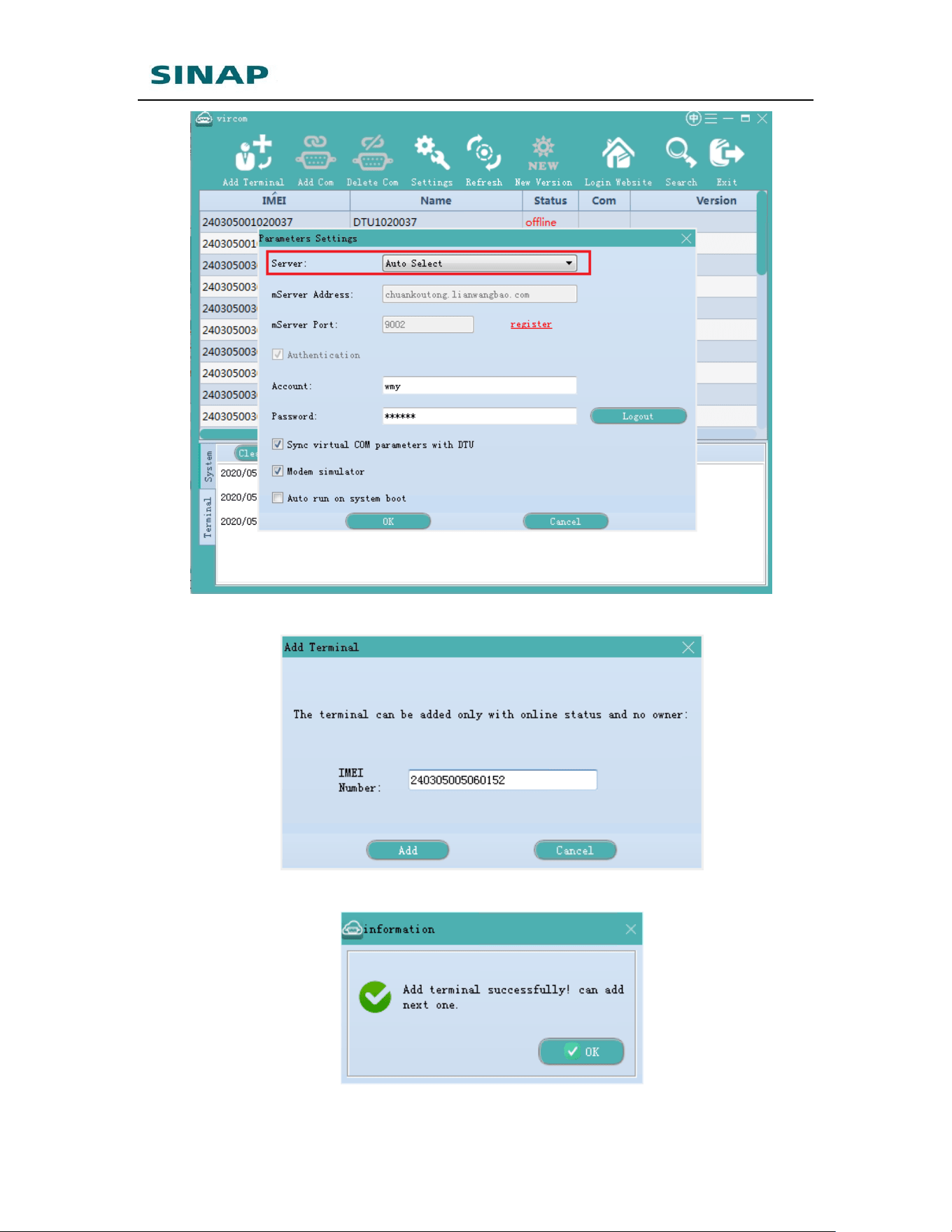
Run Vircom software, and click “Settings”, server is set to auto-selected
by default and there is no need to change; input username and
password that is applied on eYun platform.
Add terminal in Vircom by clicking “Add Terminal”, input the IMEI on
SINAPACK 200;
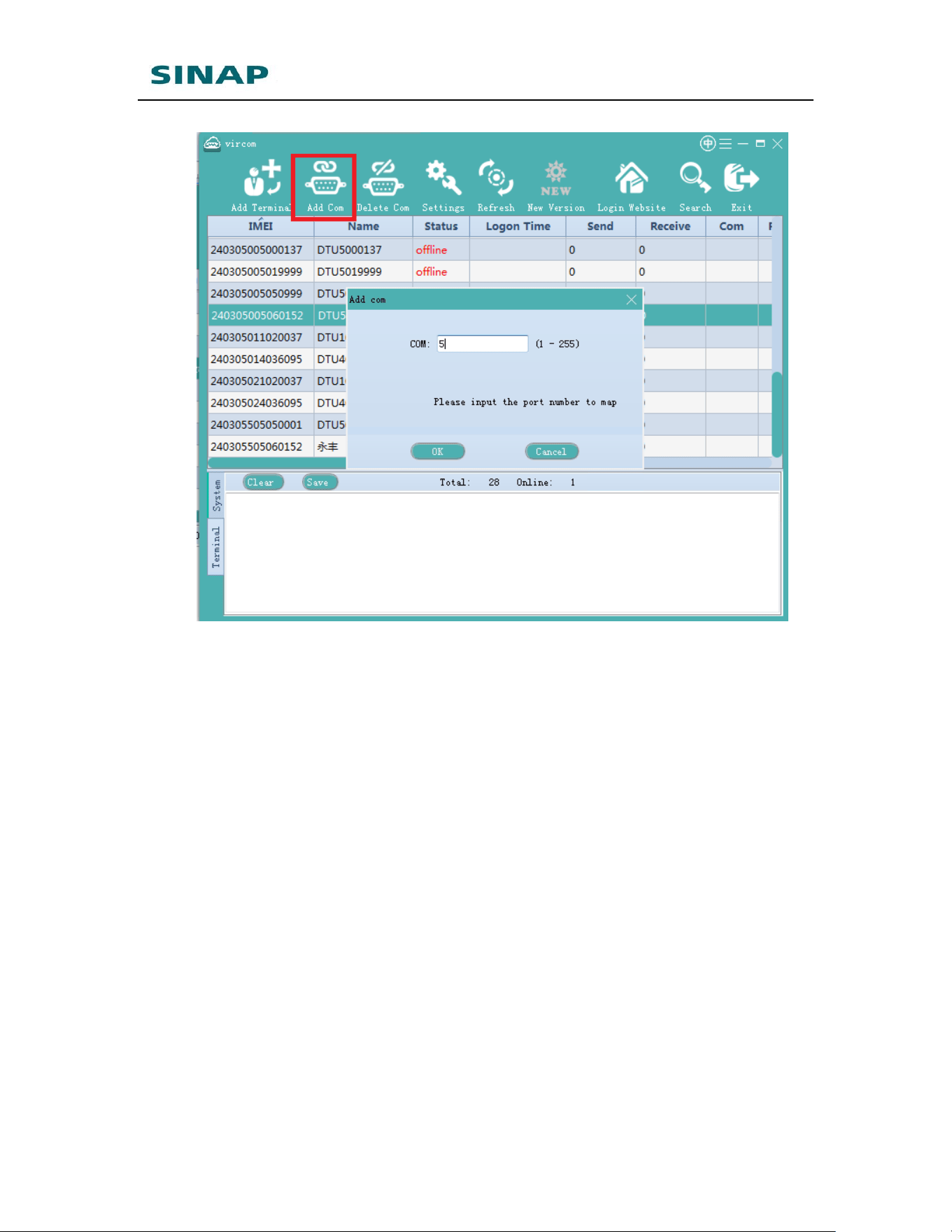
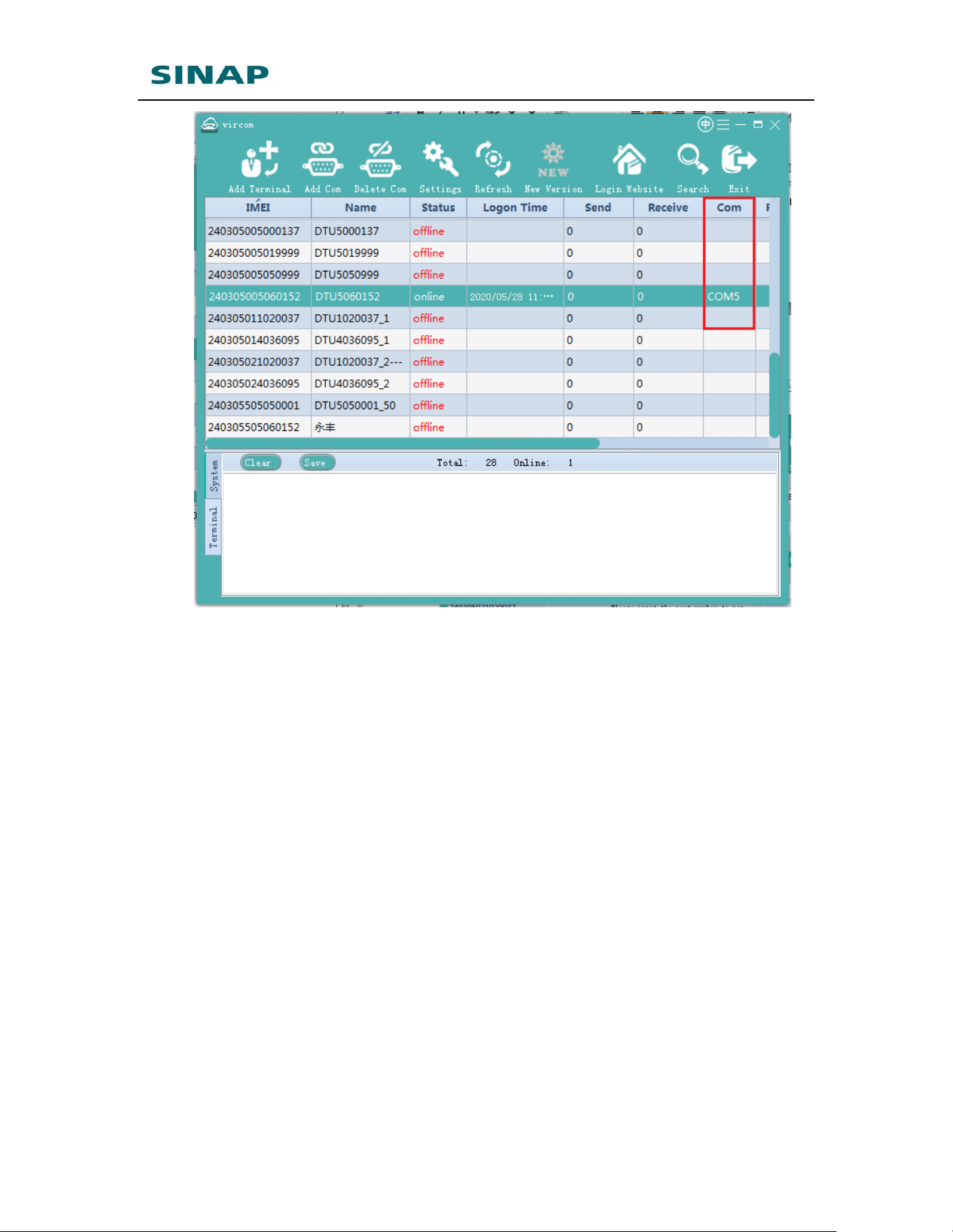
Choose the device, and then click “Add Com” to map a virtual COM for
SINAPACK 200;
Run PLC programming software to open the virtual COM and
send/receive data.
SINAPACK 200 User Manual
44
Figure Appendix 2-7: Configure Vircom
Figure Appendix 2-8: Add terminal
Figure Appendix 2-7: Succeed to add terminal
SINAPACK 200 User Manual
45
Figure Appendix 2-9: Map a virtual COM
SINAPACK 200 User Manual
46
Figure Appendix 2-10: Succeed to map virtual COM
SINAPACK 200 User Manual
47
Appendix 3: Configure SINAPACK
200 to Access Internet via
Cable/WIFI
1. Configure SINAPACK 200 to access Internet via cable network
According to the description of ch. 2.1 Configurations, login SINAPACK 200’s
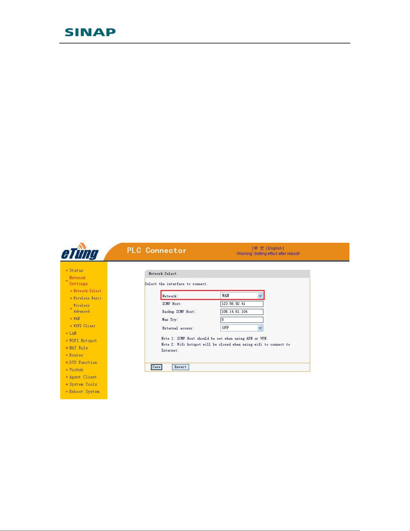
webpage, choose “Network Settings” -> “Network Select”, configure to use WAN to
access Internet.
For SINAPACK 200, the default network settings are to use WAN:
Figure Appendix 3-1: Use WAN to access Internet
Set “Network Select” as WAN, and then click “Save”;
Choose “Network Settings” -> “WAN” to configure WAN parameters;
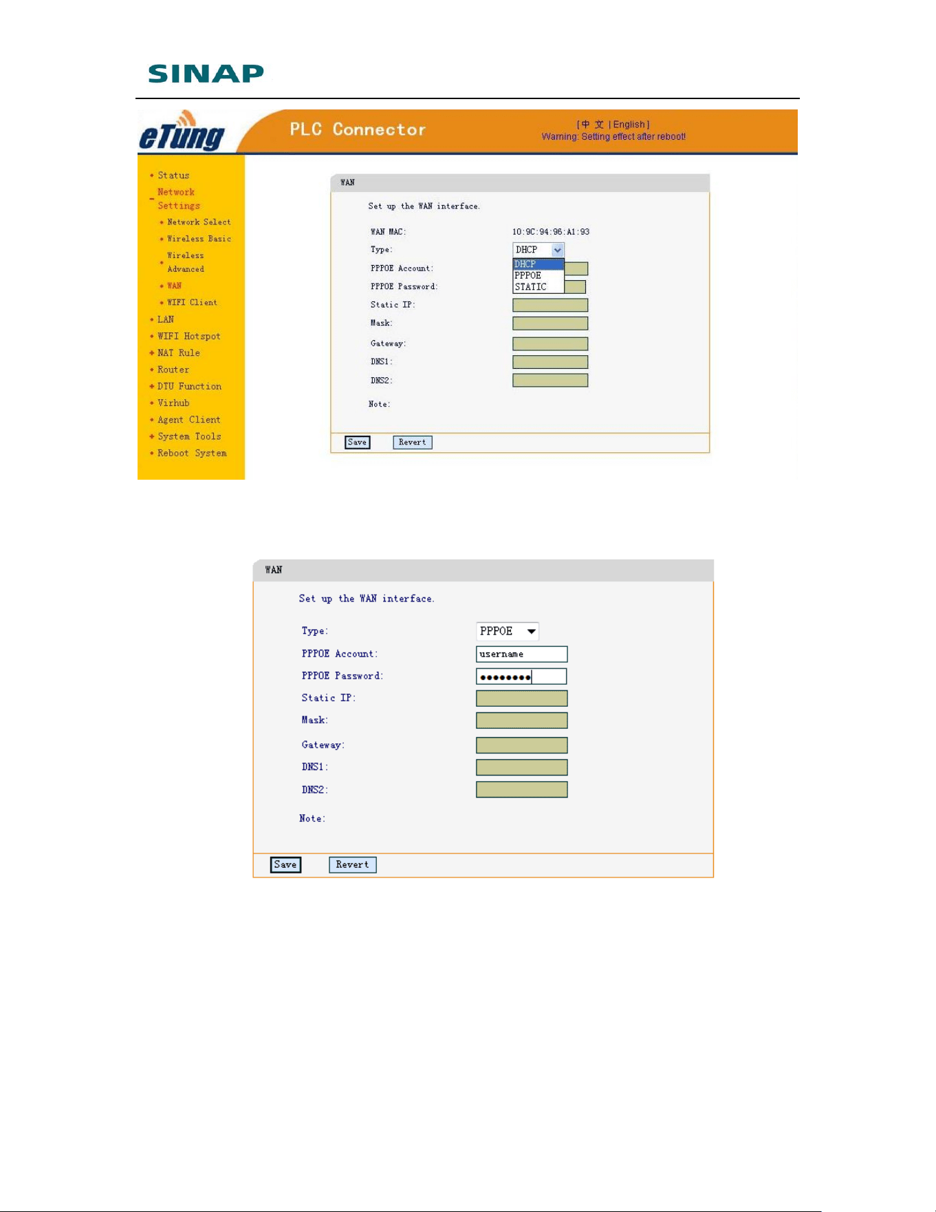
There are three kinds of types: DHCP, PPPoE and STATIC. Choose PPPoE if cable
MODEM is used to access internet, and choose DHCP or STATIC if a dedicated line
or LAN is used to access internet. Use STATIC if the IP address is static or assigned
manually, otherwise use DHCP.
SINAPACK 200 User Manual
48
Figure Appendix 3-3: Set type
When choosing PPPoE, PPPoE username and password should be set
additionally:
Figure Appendix 3-4: Configure PPPoE username and password
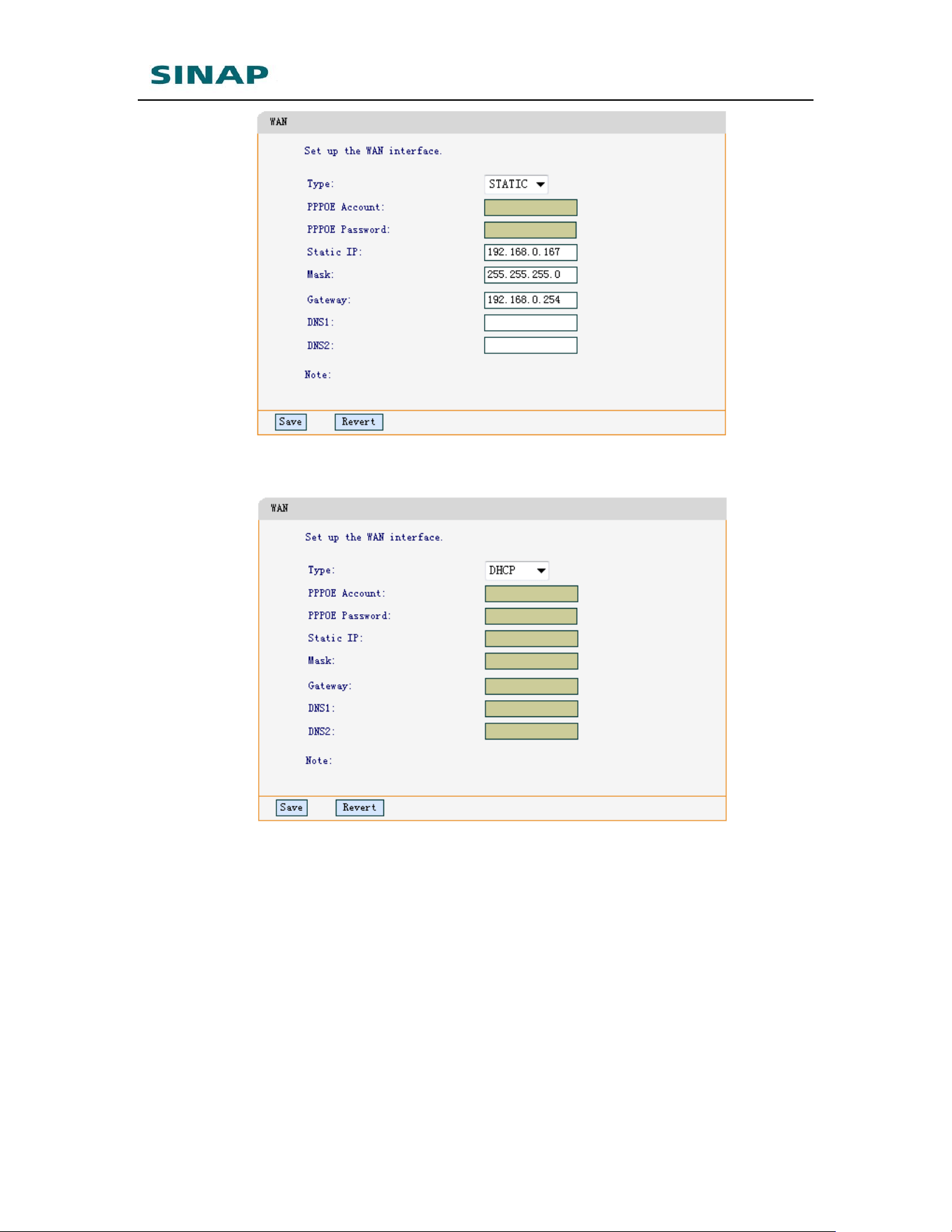
When choosing STATIC, configure static IP, net mask, gateway and DNS
accordingly:
SINAPACK 200 User Manual
49
Figure Appendix 3-5: Configure static IP
When choosing DHCP, no additional parameters need to configure:
Figure Appendix 3-6: Configure DHCP
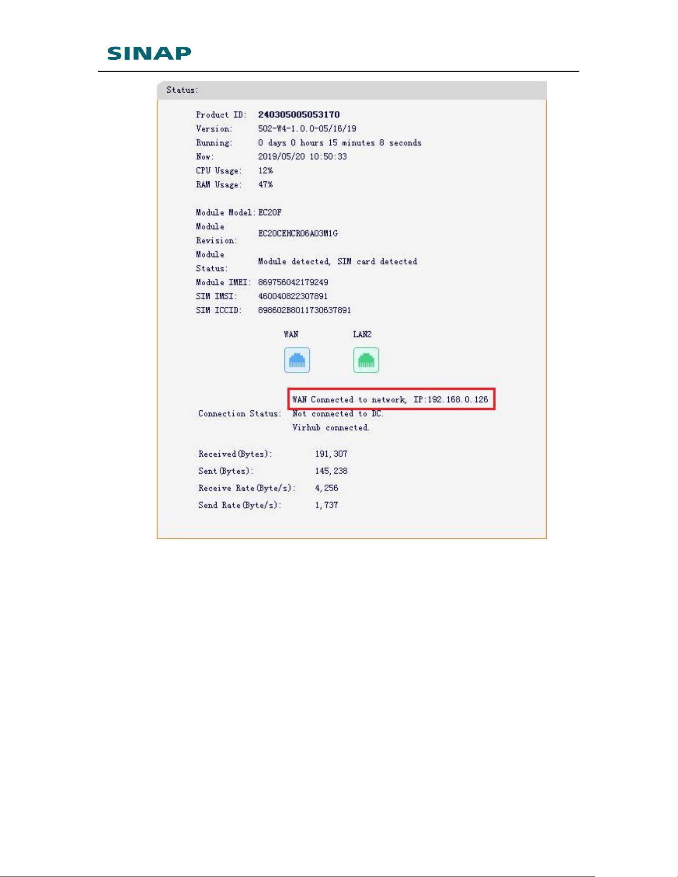
Click "Save", and plug in Ethernet cable on LAN1 (WAN) of SINAPACK 200 and
connect to the cable network, then reboot SINAPACK 200. After reboot, login
SINAPACK 200's web configuration page, it can be seen that SINAPACK 200 has
connected to the internet with WAN.
SINAPACK 200 User Manual
50
Figure Appendix 3-7: SINAPACK 200 accesses Internet via WAN
2. Configure SINAPACK 200 to access Internet via WIFI
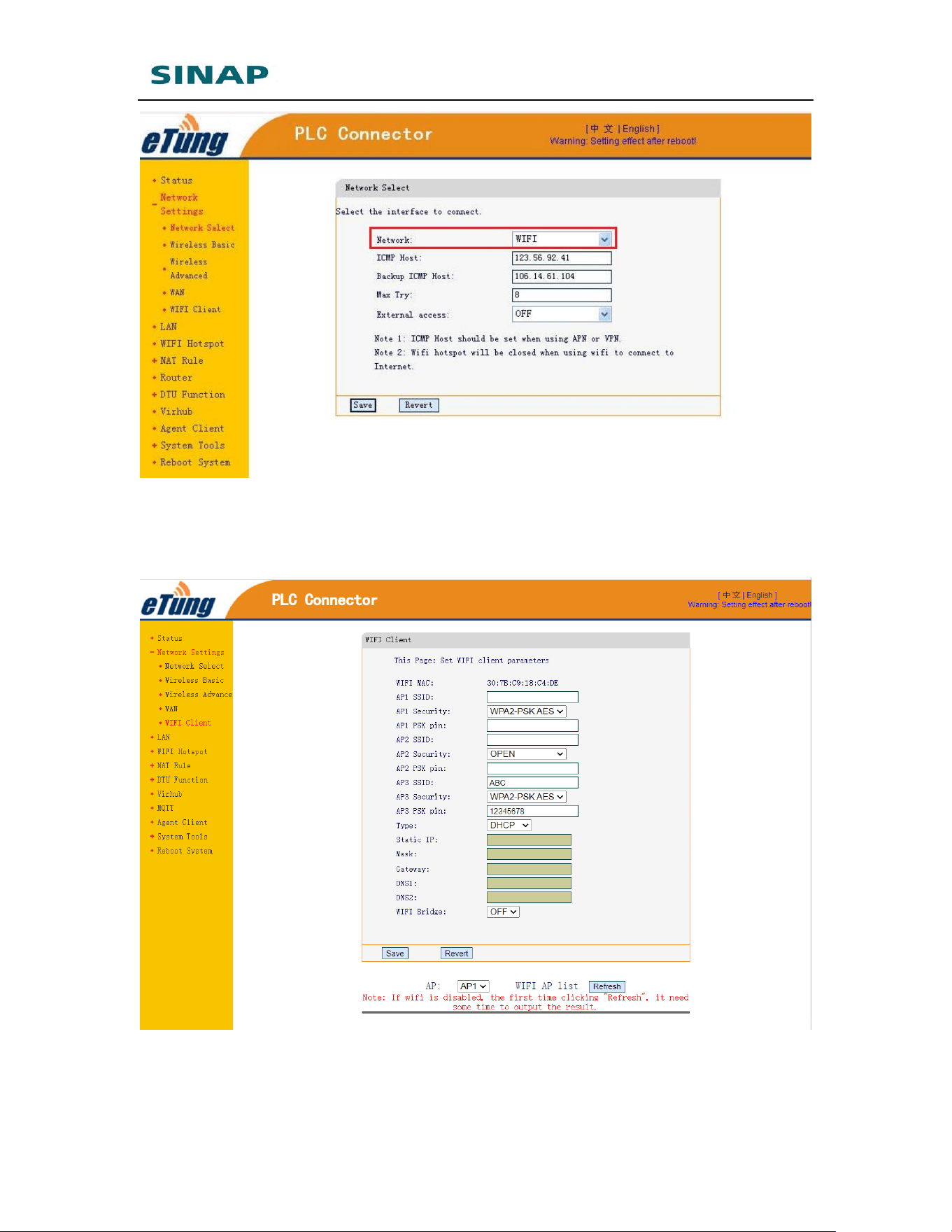
SINAPACK 200 can access Internet via WIFI. According to the description of ch.
2.1 Configurations, login SINAPACK 200’s webpage, choose “Network Settings” ->
“Network Select”, set network as WIFI, then click “Save”.
SINAPACK 200 User Manual
51
Figure Appendix 3-8: Set network as WIFI
Choose “Network Settings” -> “WIFI Client”, to configure WIFI parameters.
SINAPACK 200 supports configuring at most 3 WIFI APs. By default AP3 has SSID:
ABC and pin: 12345678.
Figure Appendix 3-9: Configure WIFI parameters – 1
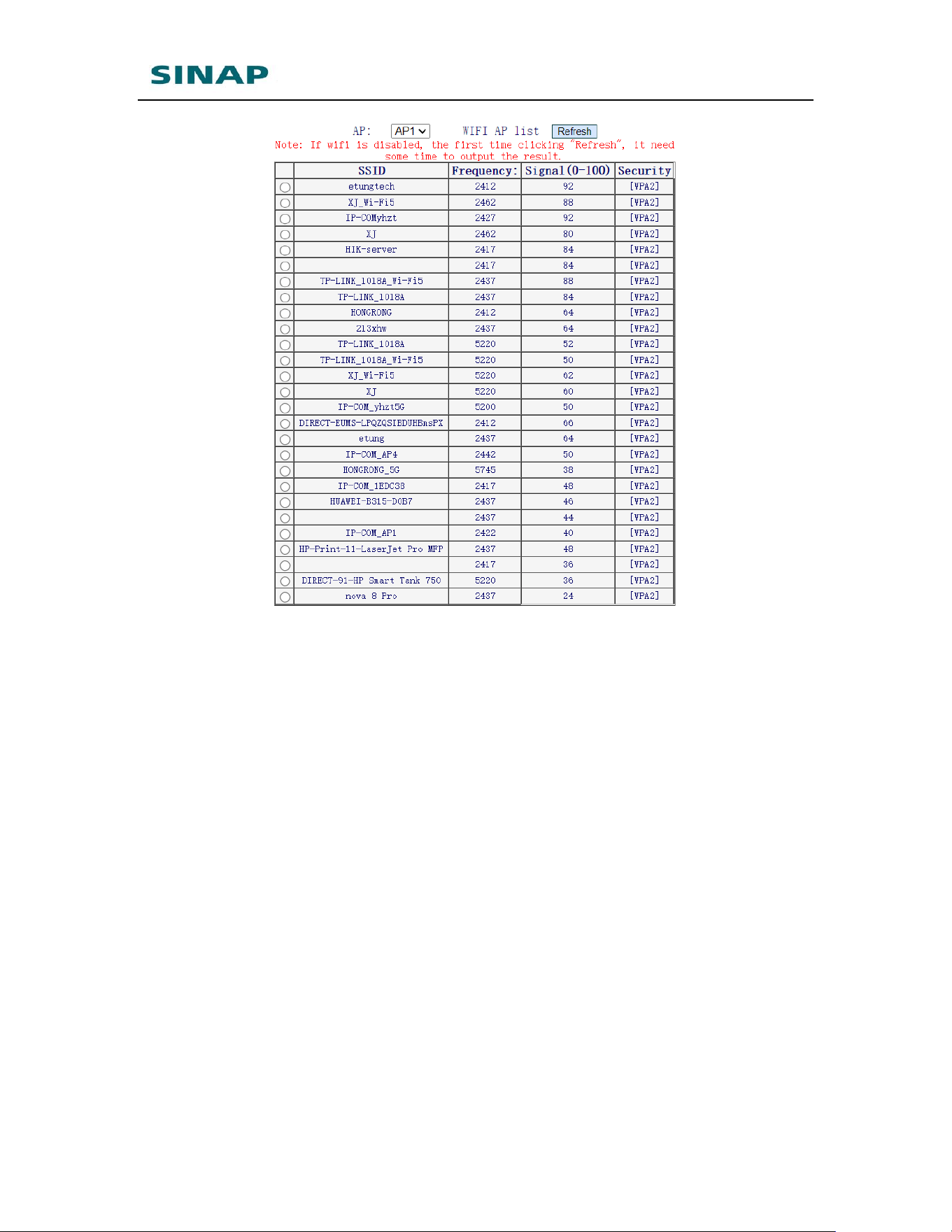
Click “Refresh” to search the WIFI APs around:
SINAPACK 200 User Manual
52
Figure Appendix 3-10: Search WIFI APs
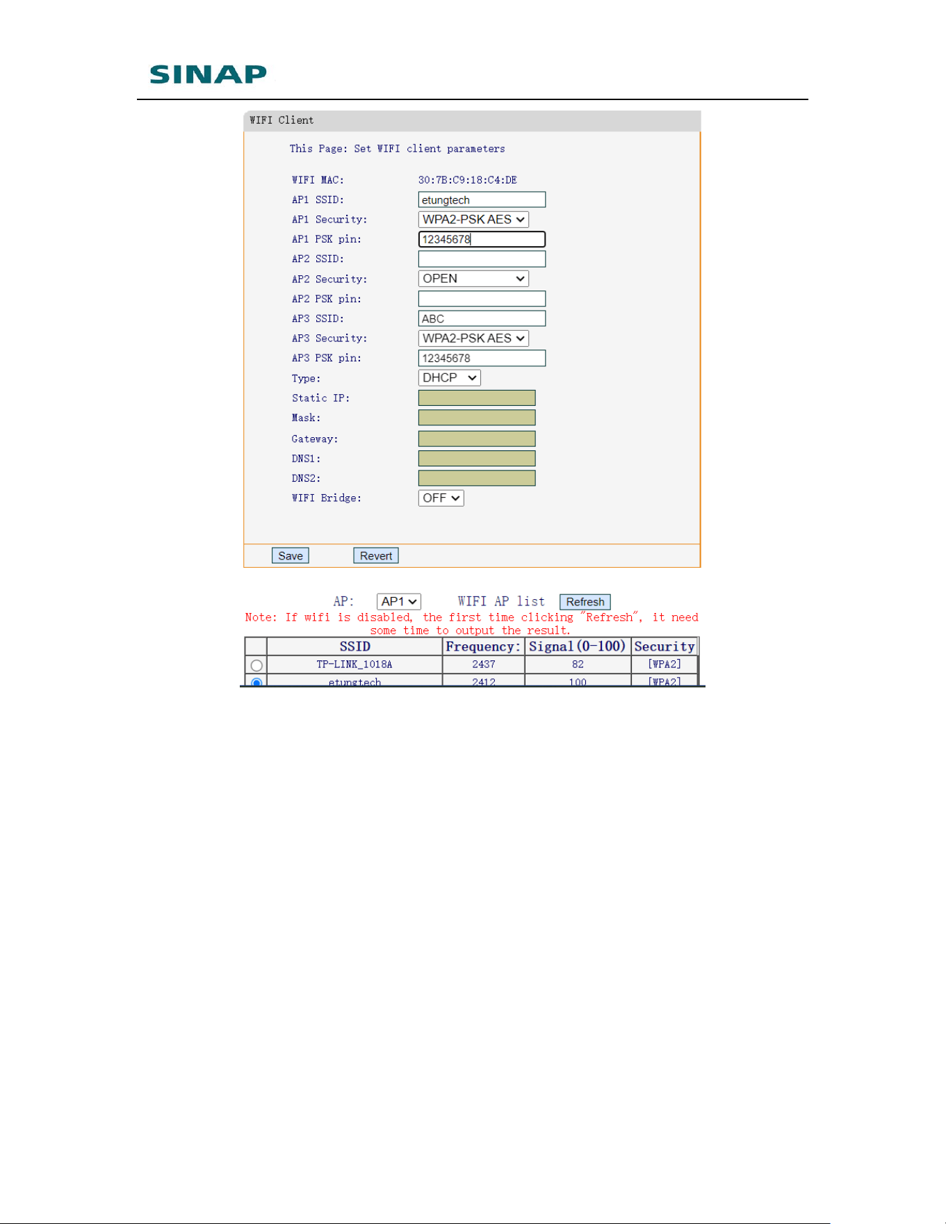
Choose WIFI AP in the list, select security type, and input pin, then click
“Save”, and reboot SINAPACK 200.
SINAPACK 200 User Manual
53
Figure Appendix 3-11: Configure WIFI parameters – 2
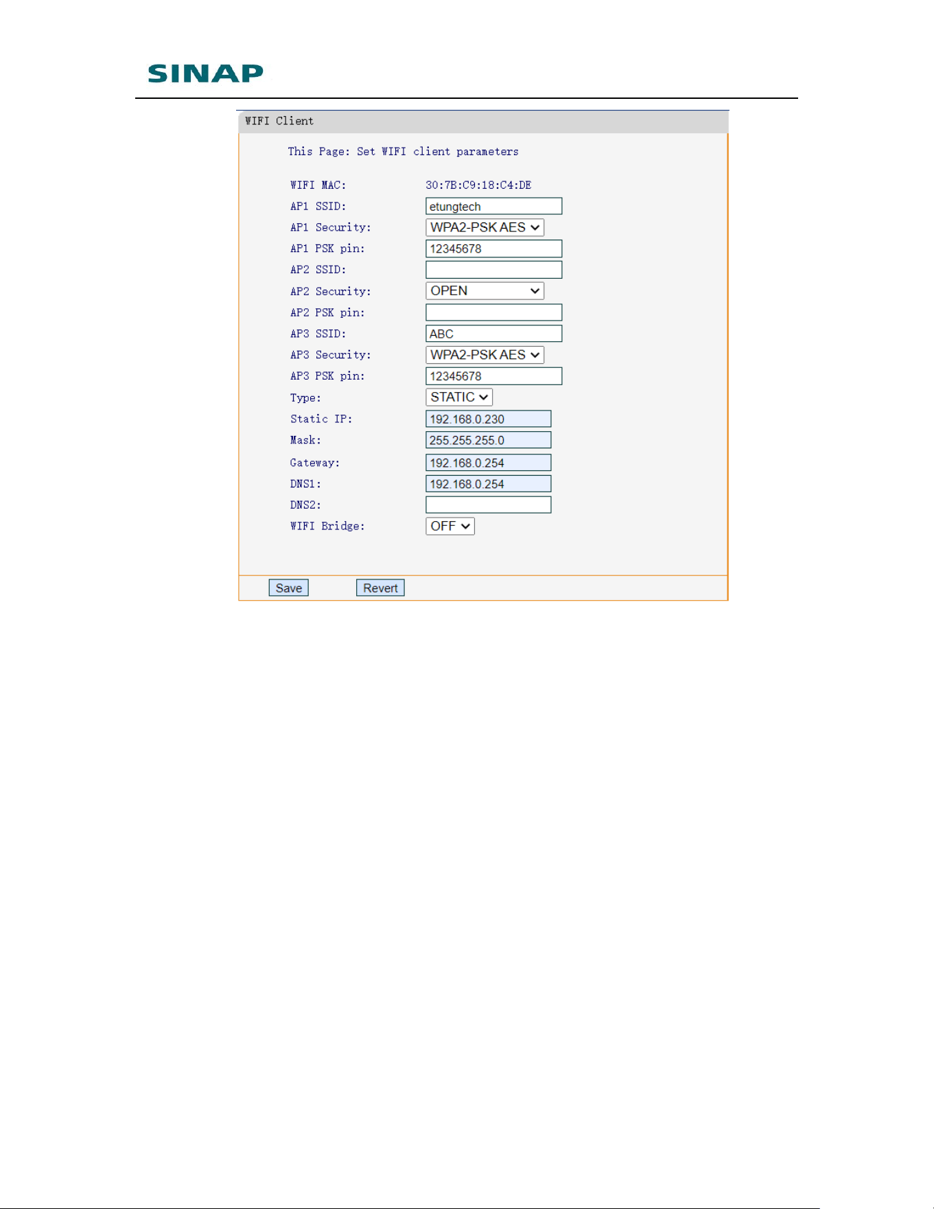
By default connection type is DHCP, i.e. get IP address dynamically. It is
also supported to assign static IP address manually, and set subnet netmask,
default gateway and DNS, as shown in the figure below:
SINAPACK 200 User Manual
54
Figure Appendix 3-12: Configure WIFI parameters – 3
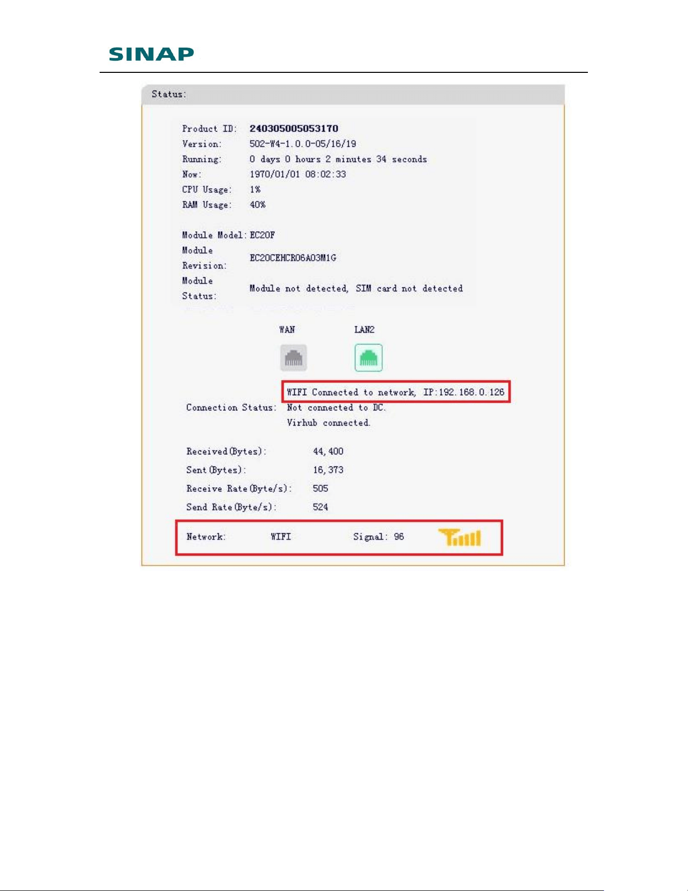
After configuration and reboot, login SINAPACK 200's web configuration page,
it can be seen that SINAPACK 200 has connected to the internet with WIFI.
SINAPACK 200 User Manual
55
Figure Appendix 3-13: SINAPACK 200 accesses Internet via WIFI
NOTE: Some SINAPACK 200 types do not have WIFI module, and then
cannot access Internet via WIFI.
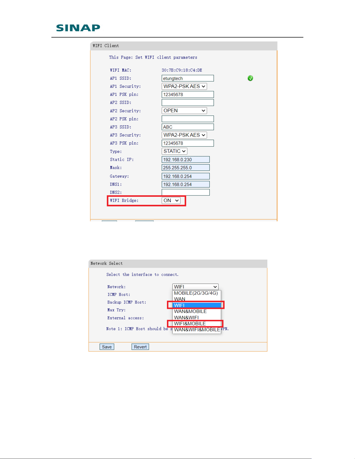
SINAPACK 200 supports WIFI Bridge, and by default it is disabled. Network
devices that connect to SINAPACK 200’s Ethernet interfaces, have IP addresses
that are different from the IP addresses that WIFI AP specifies. So the devices
that connects to SINAPACK 200’s Ethernet interfaces cannot PING devices that
connect to the WIFI AP. WIFI Bridge functionality can solve this problem. After
enabling WIFI Bridge, network devices that connect to SINAPACK 200’s
Ethernet interface can get(or set) IP addresses from WIFI AP, and then they are
in the same LAN with those devices connecting to the same WIFI AP, and they
can PING each other freely.
SINAPACK 200 User Manual
56
Note:
1. To enable WIFI Bridge, please disable WAN, and choose WIFI.
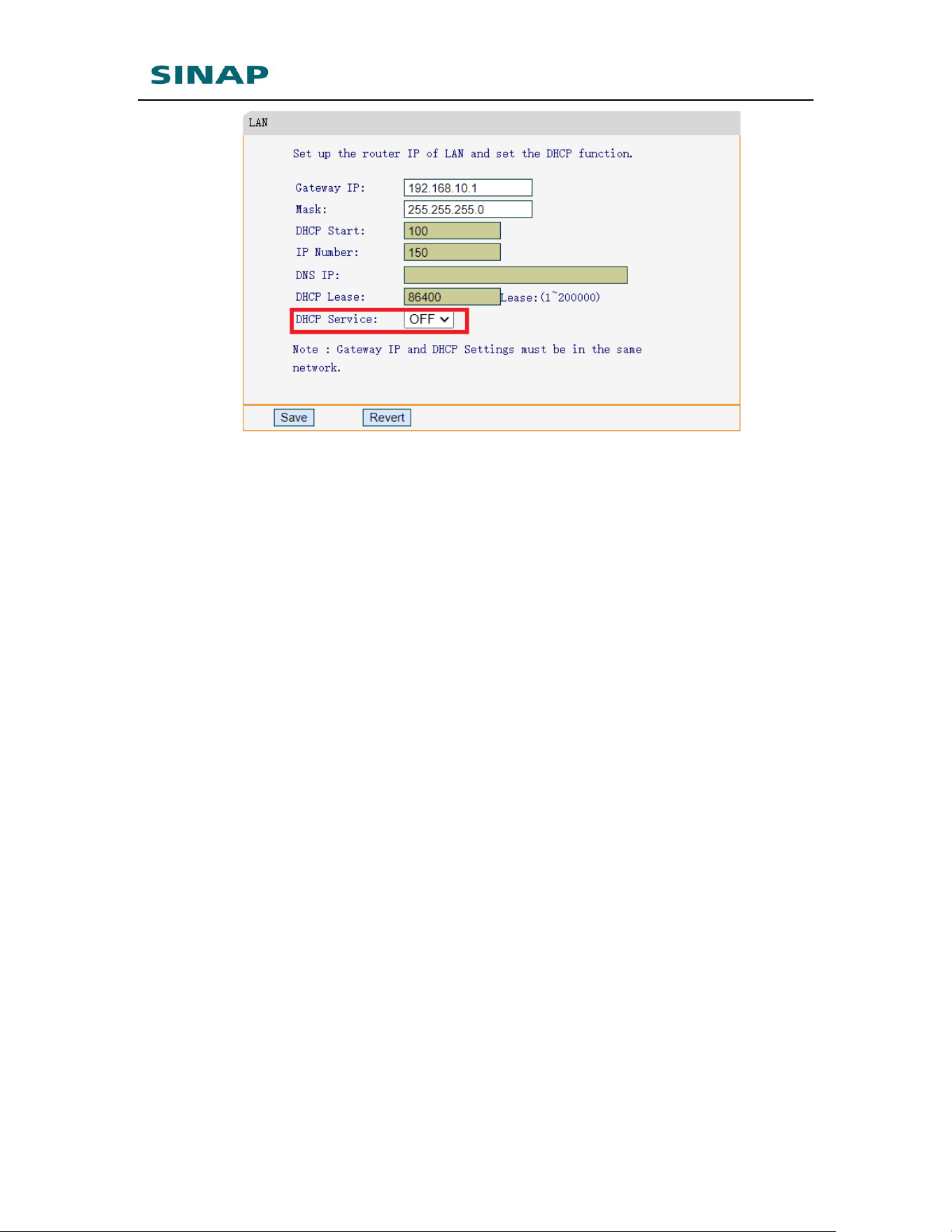
2. In case devices need to get IP automatically from WIFI AP, please
disable SINAPACK 200’s DHCP function. Otherwise, SINAPACK 200 will
specify IP to the devices, and they cannot get IP from WIFI AP.
SINAPACK 200 User Manual
57

SINAPACK 200 User Manual
58
Appendix 4: Use VNC and
SINAPACK 200 to Access and
Control Devices Remotely
VNC is the abbreviation of Virtual Network Console. It is a kind of excellent remote
control software, and it includes two parts: client software (vncviewer) and server
software (vncserver). Vncserver runs on the remote master device, and vncviewer
runs on the local pc (or mobile phone), and vncviewer connects to device that runs
vncserver and displays the desktop remotely. The basic mechanism of VNC is just
like those remote control software that run on windows: first vncviewer establishes
connection with vncserver, and then vncserver displays it’s desktop to vncviewer,
and allows the remote control of its desktop, thus implements remote control of
device.
VNC supports multiple OSs, including Windows, Linux, MAC OS, and Android; and
it is platform independent, i.e. we can use Windows PC running VNC to control
device that runs Linux or MAC OS, or use Android mobile to control touchscreen
that runs Linux.
Customers’ devices, for example, touchscreens, is located on the remote places. It
requires that PC or mobile phone can remote control the touchscreen, with
vncserver running the touchscreen, and vncviewer running on the PC (or mobile).
PC and mobile can access Internet, but cannot access the touchscreen, because
there is no network access in the place of touchscreen, or: although the
touchscreen can access Internet, it does not have public network IP, and PC (or
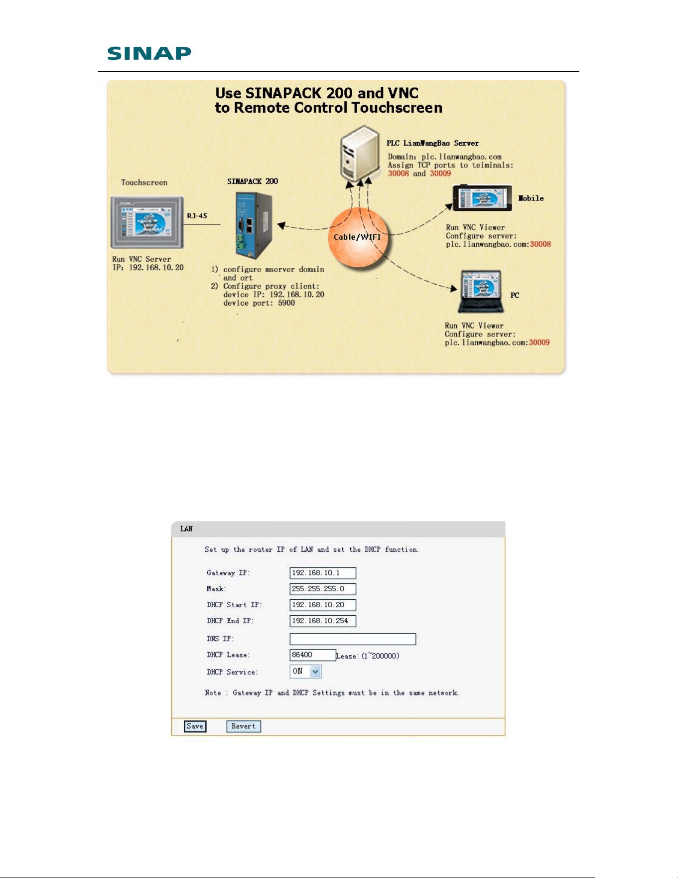
mobile) still cannot access the touchscreen remotely. SINAPACK 200 and together
with SINAPACK 200 cloud server, offer an effective and convenient solution to
control the far-end touchscreen remotely via PC or mobile. Below are details of the
solution.
SINAPACK 200 User Manual
59
Figure Appendix 4-1: Use SINAPACK 200 an VNC to remote control touchscreen
1. Install and run vncserver on the touchscreen, and run vncviewer on PC or
mobile, and PC (or mobile) can access Internet;
2. Configure touchscreen IP address: set the IP address to be in the same
IP range as SINAPACK 200’s LAN IP, for example 192.168.10.20. Check
SINAPACK 200’s LAN IP range in its web configuration page, by default
192.168.10.* , as shown in the figure below:
Figure Appendix 4-2: Configure SINAPACK 200 LAN IP – 1
Modify SINAPACK 200 LAN IP as required, click Save and reboot SINAPACK
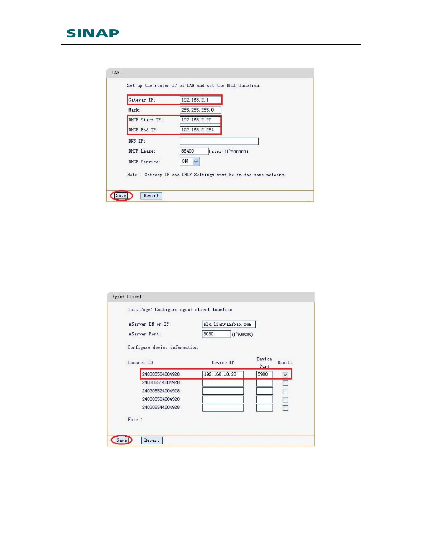
SINAPACK 200 User Manual
60
200.
Figure Appendix 4-3: Configure SINAPACK 200 LAN IP – 2
3. Configure agent client on SINAPACK 200
Login SINAPACK 200 web configuration page, choose “Agent Client” , mServer
DN or IP is plc.lianwangbao.com and mServer port is 8080 by default, that is
eTung mServer, normally use the default settings, until customer builds its own
mServer. Then configure device information, including touchscreen’s IP (for
example, 192.168.10.20) and vncserver’s listening port (for example, 5900),
and tick “Enable”, press Save and reboot SINAPACK 200.
Figure Appendix 4-4: Configure agent client
SINAPACK 200 supports multiple vncviewers’ remote access from different PCs
(or mobiles). This can be done by supporting multiple channels on agent client
functionality. Configure multiple lines in agent client configuration, and enable
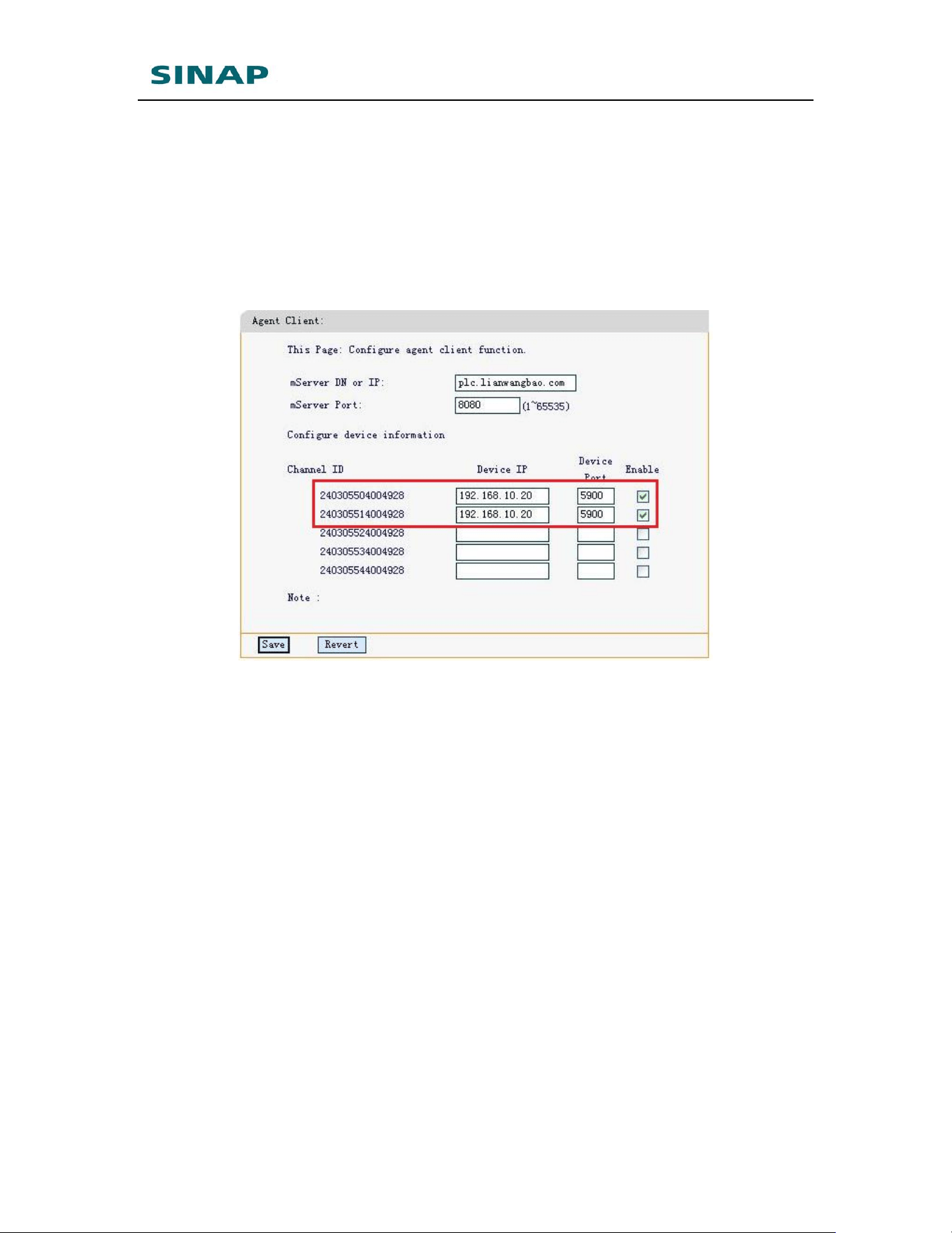
SINAPACK 200 User Manual
61
all of them. For example, configure two channels as shown in the figure below,
each channel has touchscreen’s IP as device IP, and vncserver’s listening port
as device port. This allows two PCs (or mobile phones) to remote control the
touchscreen at the same time, thus implements device remote control in
different locations. SINAPACK 200support at most 5 channels, and each
channel has a 15-byte channel ID. The channel ID is derived from SINAPACK
200’s IMEI. For example, SINAPACK 200’s IMEI is 240305001234567, then the
agent clients’ channel ID is 2403055X1234567, and X can be 0~4, to represent
one of the five channels.
Figure Appendix 4-5: Configure multi-channel agent client
4. Connect SINAPACK 200 and touchscreen with RJ45 net cable, plug SIM
card in SINAPACK 200, tighten the antenna, and power on SINAPACK
200.
5. Assign TCP port for terminals on SINAPACK 200 server
Open browser on PC, visit SINAPACK 200 server’s web page: plc.SINAPACK
200.com. First register a user and enable it, and then login with username and
password;
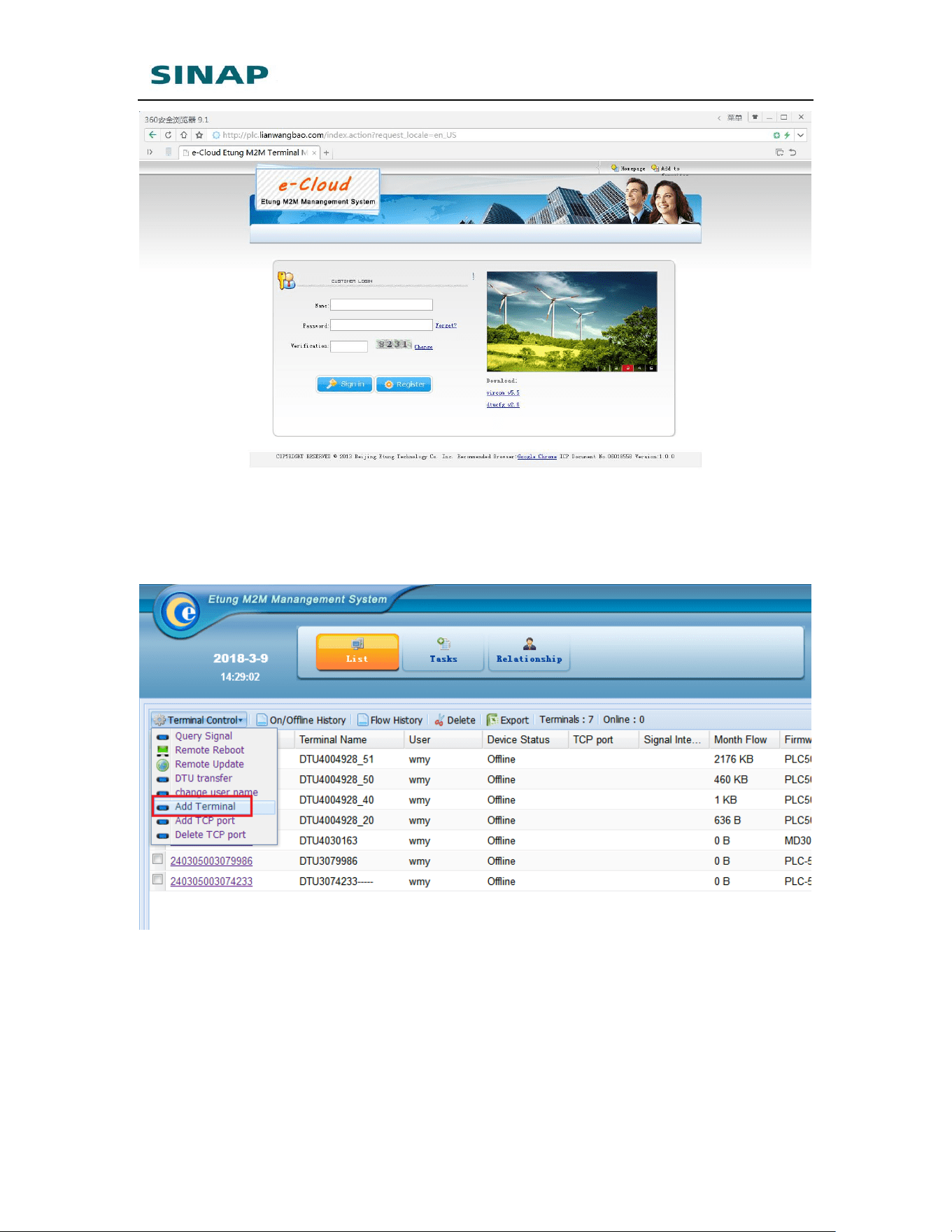
SINAPACK 200 User Manual
62
Figure Appendix 4-6: Login SINAPACK 200 server
Click “Terminal Control” -> “Add Terminal”,
Figure Appendix 4-7: Add terminal
Input the channel ID corresponding to the agent client, for example:
240305501234567:
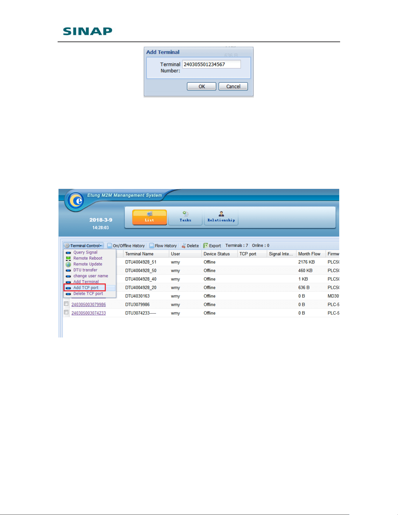
SINAPACK 200 User Manual
63
Attention: terminal can be added only when it is online. If it fails to add
terminal, make sure SINAPACK 200 has connected online in SINAPACK 200
server, or ask eTung technical support for help.
After terminal is added, assign TCP port for the terminal: Click the terminal in
terminal list, then click “Terminal Control” -> “Add TCP port”. System prompts:
“Add TCP port command has been submitted successfully!” Then in the
terminal list it can be seen the terminal has been assigned a TCP port, as shown
in the figure below:
Figure Appendix 4-8: Add TCP port
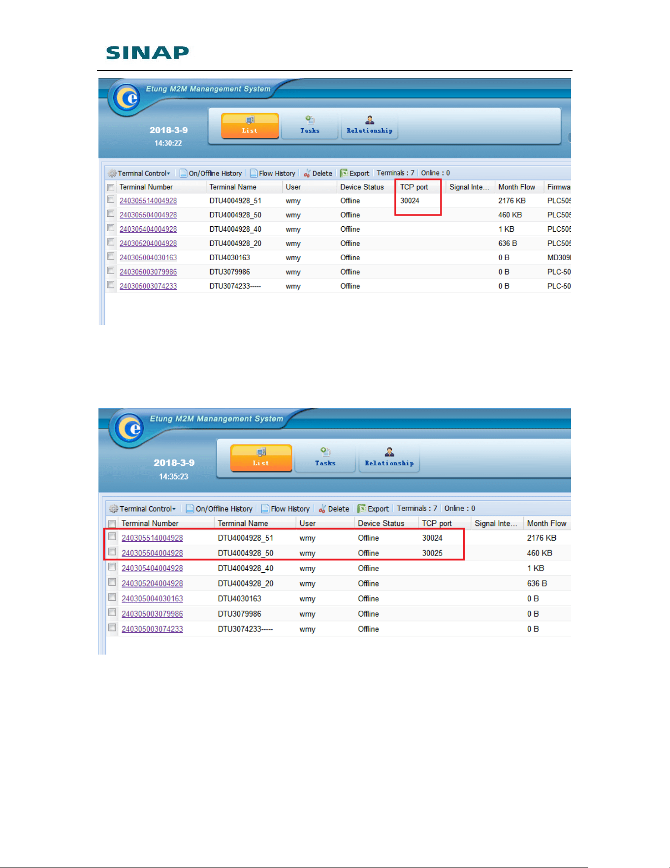
SINAPACK 200 User Manual
64
If multiple channels are configured in SINAPACK 200’s agent client, then add
terminal for each independent channel and assign TCP port for the terminal
accordingly. As shown in the figure below, two terminals and corresponding
TCP ports are added:
Figure Appendix 4-9: Add TCP port for each terminal
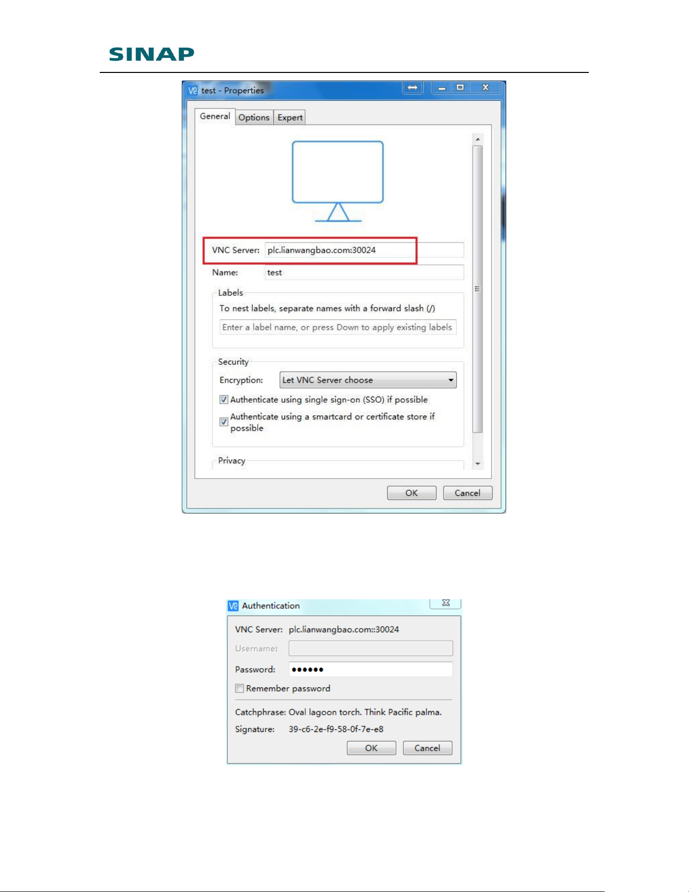
6. Use vncviewer on PC or mobile to remote control touchscreen
Run vncviewer in PC or mobile, input server information as LianWangBao
server’s domain plus the TCP port assigned in step 5, as shown in the figure
below:
SINAPACK 200 User Manual
65
Figure Appendix 4-10: Use vncviewer to access LianWangBao server’s TCP port
Click “OK”, then there will be a warning dialog, and then prompts the password
dialog. Input the password to verify, then the remote touchscreen’s desktop
will be shown on PC (or mobile).
Figure Appendix 4-11: Input password
Attention:

SINAPACK 200 User Manual
66
1) If multiple PCs (or mobile phones) access touchscreen at the same time,
make sure each PC use an independent channel, i.e. in vncviewer’s server
information use different TCP port for different channels, otherwise the
connections will be lost and PCs cannot work correctly.
2) The solution above is just one of device remote access solutions. In fact, to
support PCs’ remote access on touchscreen, Virhub + VNC is another
effective solution. Please refer to Appendix 1 for details on how to use
Virhub.
SINAPACK 200 User Manual
67
Appendix 5: Use SINAPACK 200 IP
Virtual Mapping together with
Virhub to Distinguish Devices with
Same IP
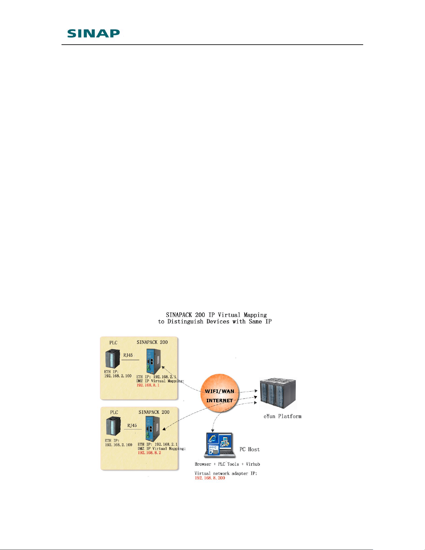
Some projects have devices, i.e. PLCs, with a fixed IP address by default.
SINAPACK 200 is used to implement devices’ remote access. However, the
devices are configured with the same default IP, and the monitoring center
cannot distinguish them with IP. Virhub together with SINAPACK 200 IP
virtual mapping can solve this problem.
SINAPACK 200 User Manual
68
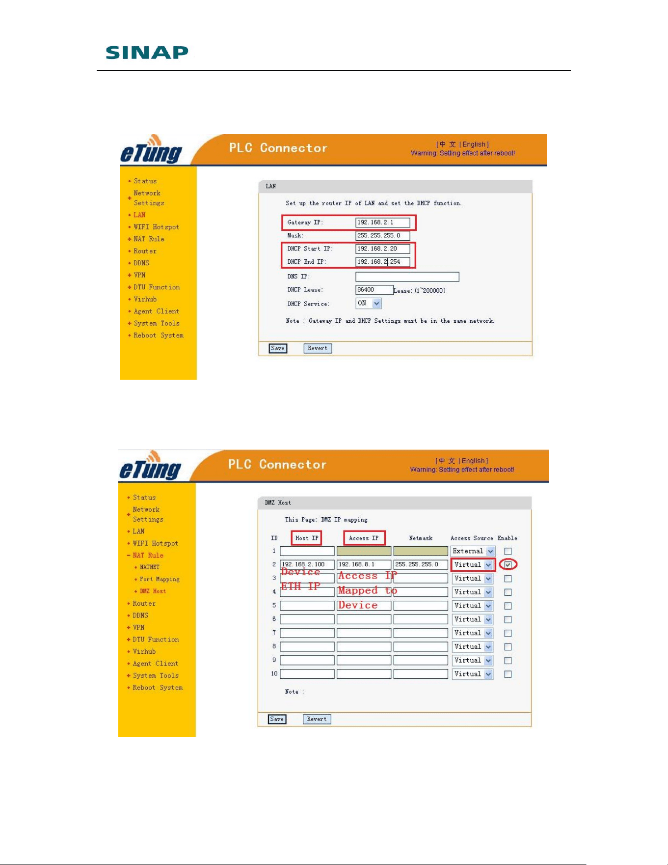
1. Use Ethernet cable to connect device with SINAPACK 200;
2. Configure SINAPACK 200 Ethernet IP to be in the same IP range as
device Ethernet IP, for example: 192.168.2.*;
3. Configure IP virtual mapping, map the device’s IP to some IP (Access IP)
in a different IP range, for example: 192.168.8.1, and make sure
different devices are assigned to different IPs;
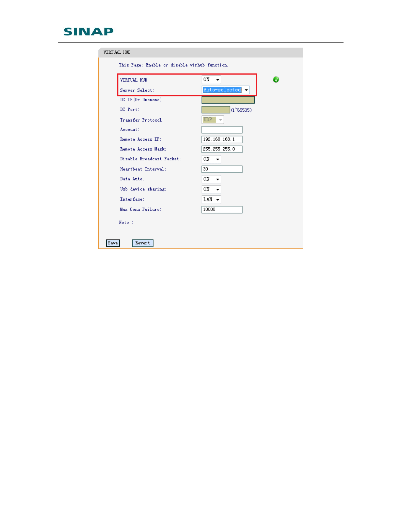
4. Enable Virhub in SINAPACK 200;
SINAPACK 200 User Manual
69
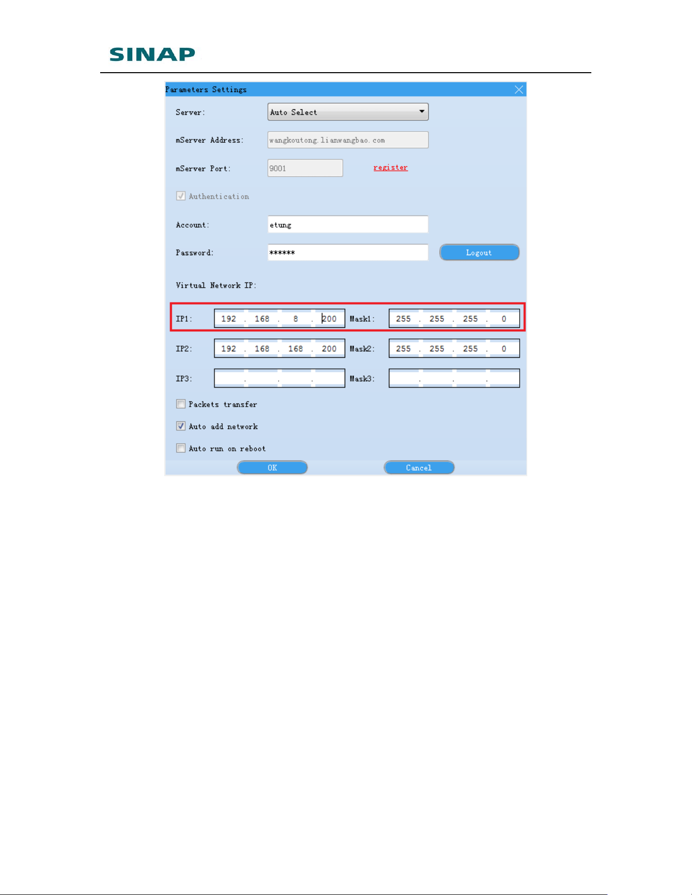
5. Run Virhub software on host PC, and set virtual network adapter IP as
in the same IP range as the access IPs mapped to devices;
SINAPACK 200 User Manual
70
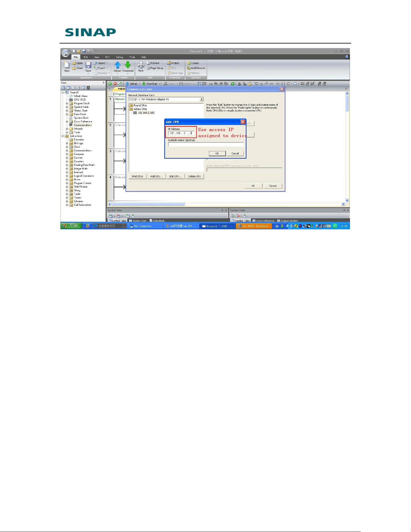
6. Use the access IPs to communicate with devices.
SINAPACK 200 User Manual
71

SINAPACK 200 User Manual
72
Appendix 6: SINAPACK 200’s
MODBUS TCP Interface Description
SINAPACK 200 has built-in MODBUS TCP protocol, and as MODBUS TCP slave,
MODBUS TCP client can get system time, SINAPACK 200 current status, signal
strength, SINAPACK 200 serial ID, etc. Below is the brief description of
SINAPACK 200’s MODBUS TCP interface.
✓ MODBUS device address: 0x01
✓ MODBUS TCP port: 502
✓ Max connections: 32
✓ Protocol addresses base 0
✓ 16-bit high first
✓ 32-bit low first
Function
Description
Variable
Address Offset
Variable
Datatype
Variable
Description
03
Read
Holding
Register
1~6
Int16
System time: Year,
Month, Day, Hour,
Minute, and Second.
7
Int16
Signal strength
8
Int16
Current network:
0: No connection
1: Cable
2: WIFI
9~12
Reserved
13
Int16
SINAPACK 200 current
status
0: Running
1: Breakdown
14
Int16
CPU usage, with value
0~100
15
Int16
Memory usage, with
value 0~100
16
Int16
Positioning status, 0:
Invalid, 1: Valid
17~18
Float32
Running time, unit: hour
19~20
Reserved

SINAPACK 200 User Manual
73
21~35
Int16
SINAPACK 200 serial ID,
15 digits, encoding with
BCD
36
Reserved
SINAPACK 200 User Manual
74
Appendix 7: SINAPACK 200’s
Enhanced DMZ Function
In case SINAPACK 200 chooses WAN or WIFI network, if some PC in the same
WAN/WIFI network needs to connect to devices under SINAPACK 200, the
enhanced DMZ function can be enabled.
By default, only one host can be specified for DMZ host. The enhanced DMZ allows
multiple hosts.
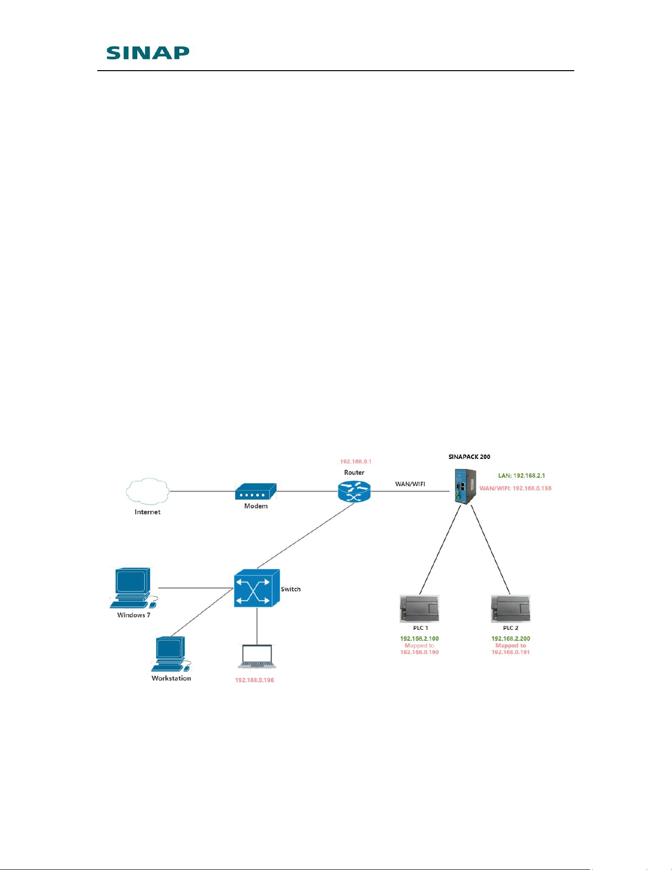
As shown in the figure below, SINAPACK 200 connects to network via WAN/WIFI,
and gets IP address 192.168.0.*. PLC 1 and PLC 2 connects to SINAPACK 200, with
IP address 192.168.2.100 and 192.168.2.200. One PC in the same WAN network
has IP 192.168.0.196, and the PC needs to connect to PLC 1 and PLC 2.
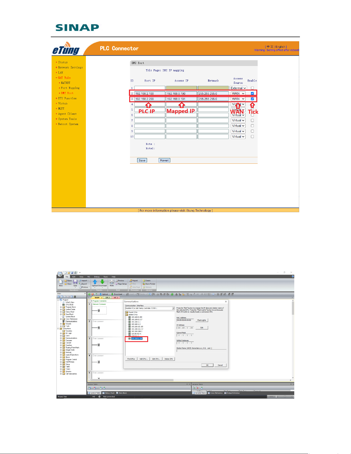
To implement this, configure two rules in DMZ, as shown in the figure below:
SINAPACK 200 User Manual
75
After configuration, save and reboot SINAPACK 200.
Then, PC in the WAN network can access PLC 1 via IP: 192.168.0.190, and PLC 2
with IP: 192.168.0.191.
For example, to download/upload PLC program:
SINAPACK 200 User Manual
76
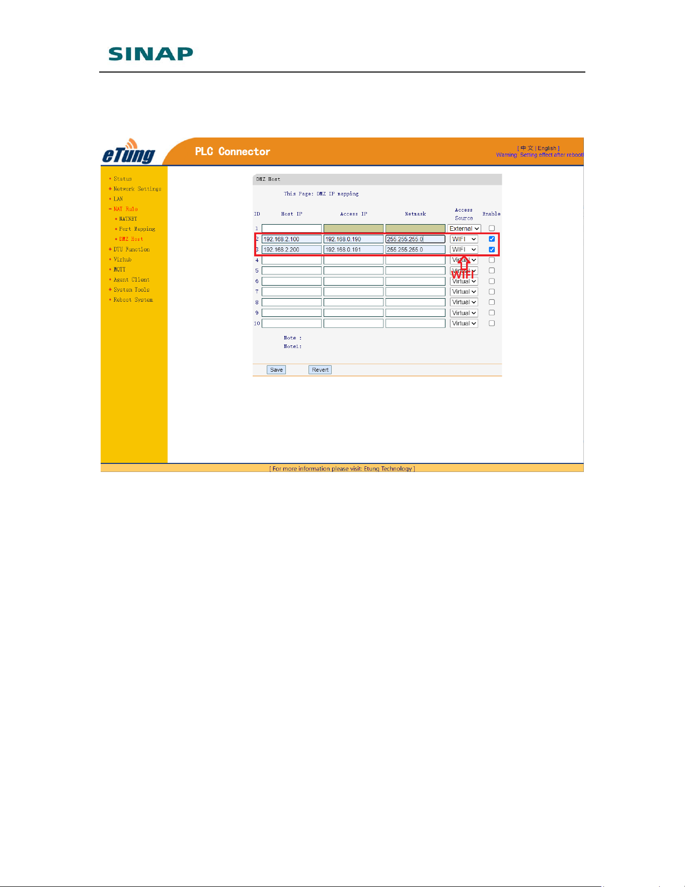
Similarly, in case SINAPACK 200 connects to WIFI network, the DMZ rules are
configured below:
Attention:
In case WAN is specified in the rules, please enable WAN network; and in case WIFI
is specified in the rules, please enable WIFI network. Go to Network Settings -->
Network Select, and choose WAN or WIFI to enable the corresponding network.

SINAPACK 200 User Manual
77
FCC Statement:
Please take attention that changes or modification not expressly approved by the
party responsible for compliance could void the user’s authority to operate the
equipment.
This device complies with Part 15 of the FCC Rules. Operation is subject to the following
two conditions:
(1) This device may not cause harmful interference, and
(2) This device must accept any interference received, including interference that may
cause undesired operation.
After connecting to WIFI, the device can be used.
This equipment complies with FCC radiation exposure limits set forth for an
uncontrolled environment. This equipment should be installed and operated
with minimum distance 20cm between the radiator & your body.