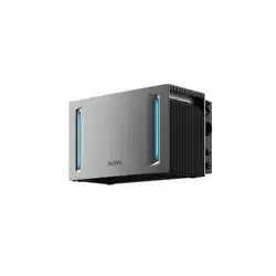
LumeGret A4000
Instruction Manual

EN
1
Table of contents
1 Product Introduction.....................................................................03
2 Pre-Installation..............................................................................06
3 Installation Steps...........................................................................07
4 Specifications.................................................................................13
5 EU Declaration of Conformity.....................................................14
6 Warranty Exclusions......................................................................15

EN
2
DISCLAIMER
This product includes essential printed documentation required for setup and basic
usage. Improper use may result in serious injury damage, or property loss. By using this
product, you agree to and accept all terms outlined in the product documentation. MOVA
is not liable for losses, damages, or injuries caused by misuse or non-compliance.
·
Read this document and other related product documentation before any operation.
·
The installation of this product must comply with all applicable local regulations, codes, or
standards.
·
An overcurrent circuit breaker must be installed between this product and the grid.
·
When the photovoltaic (PV) array is exposed to light, it supplies direct current voltage to the
power conversion equipment (PCE).
·
Use insulation tools and wear personal protective equipment when installing, servicing, or
maintaining this product.
·
Install this product in a tidy, dry, and well-ventilated environment.
·
Keep the product out of reach of children and pets. If the product is to be used near children,
they should be closely supervised.
·
Before making any electrical connections, ensure that any load to be connected (e.g. devices
or equipment intended to be powered by this product) is powered off.
·
Always pull the plug instead of the cord when disconnecting the product to reduce the risk of
damage to the electric plug and cord.
·
Do not put fingers or hands into the product.
·
Do not expose this product to direct sunlight, rain, and snow.
·
Do not expose this product to strong electromagnetic fields to avoid radio interference.
·
Do not install or operate this product near flammable, explosive, corrosive,or caustic sources.
·
Do not install or operate this product during extreme weather events such as lightning, heavy
rain, or strong wind.
·
Do not subject this product to severe impacts, vibrations, or drops to prevent physical
damage.
·
Do not drag, squeeze, step on this product, or throw it into the fire, as there is a risk of
explosion.
·
Do not use any damaged cords or cables with this product.
·
Do not damage, deface, or remove any labels on this product.
·
Do not disassemble, repair, or modify this product by yourself for any maintenance or service,
contact MOVA Customer Service.
·
Do not use any unofficial or unrecommended components and accessories.
·
For any replacements, please contact MOVA for further assistance.
·
Do not clean the product with flammable or toxic solvents. Wipe it with a dry soft cloth.
·
Do not place heavy objects (>40 kg) on the product.
EN
3
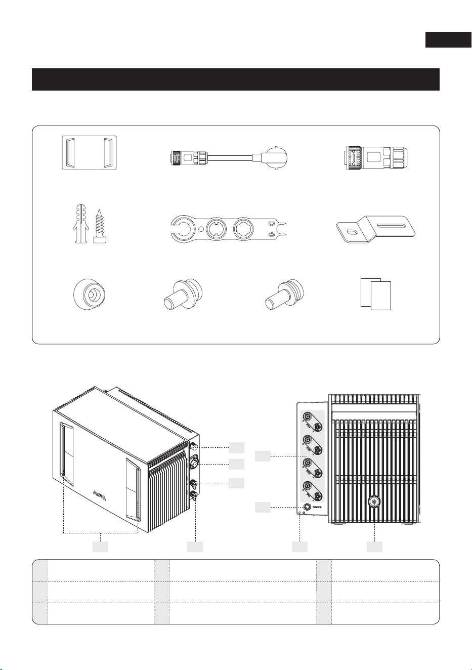
1 Product Introduction
1.1
Package List
1.2 Product Overview
2
51
3
8 9
Antenna
AC Outlets
Indicator LED Light
PV TerminalsBackup Terminal
Grid Energy Dispatch Connect
1
2
4
5
7
Meter Parallel Connector
7
Rubber Feet
×4
Flat head
screw(M4x10) ×4
Mounting Plate
×2
Flat head
screw(M5x10) ×4
MC4 Wrench
×1
AC Power Cord
×1
Expansion Screw
x2
LumeGret A4000
×1
RS485 Connector
×1
Documents
4
6
3
6
Ground Screw Hole
8
Power Button
9
EN
4
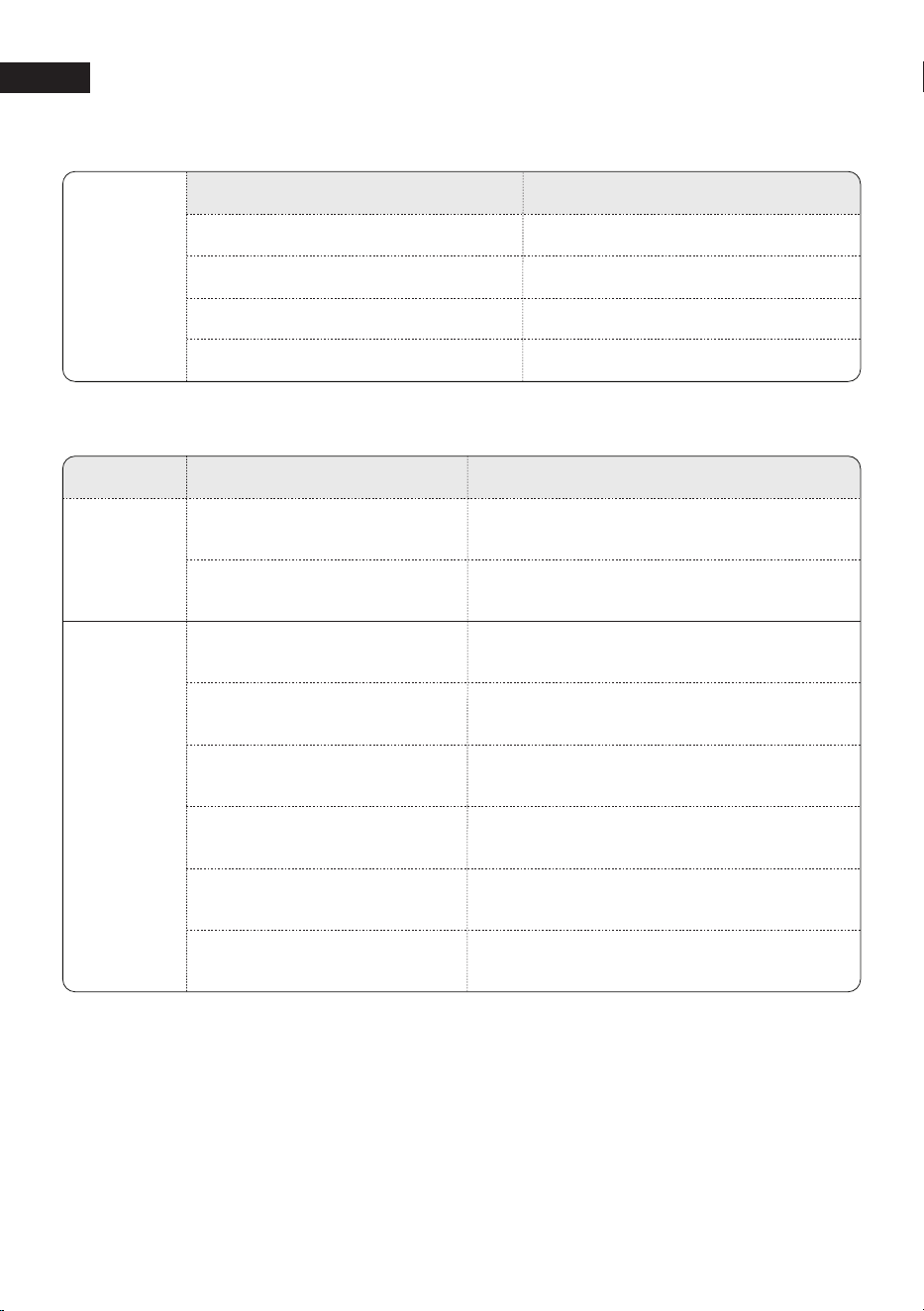
1.3 Button Controls
Action
Button
Status
Press for 3 seconds
Turn LumeGret A4000 offPress for 4 seconds
Turn LumeGret A4000 on
Check battery levelPress once
Reset bluetooth and Wi-FiPress three times
1.4 LED Indicator
Status
LED
Light Bar
Description
Powered On
The light bar changes according to
battery level
Battery level
The light bar lights up
and turns off after 30 seconds.
The center LED illuminates toward both sides,
and then cycles again
Connecting to the network...
The center LED illuminates toward both sides,
and turns off after 30 seconds
Network connection successful
The blue LED strip in the middle will light up
in a running pattern
Upgrading firmware
Flashing redError or Warning
OffPower Off
Solid LightPower On
Button
Light
Light
EN
5
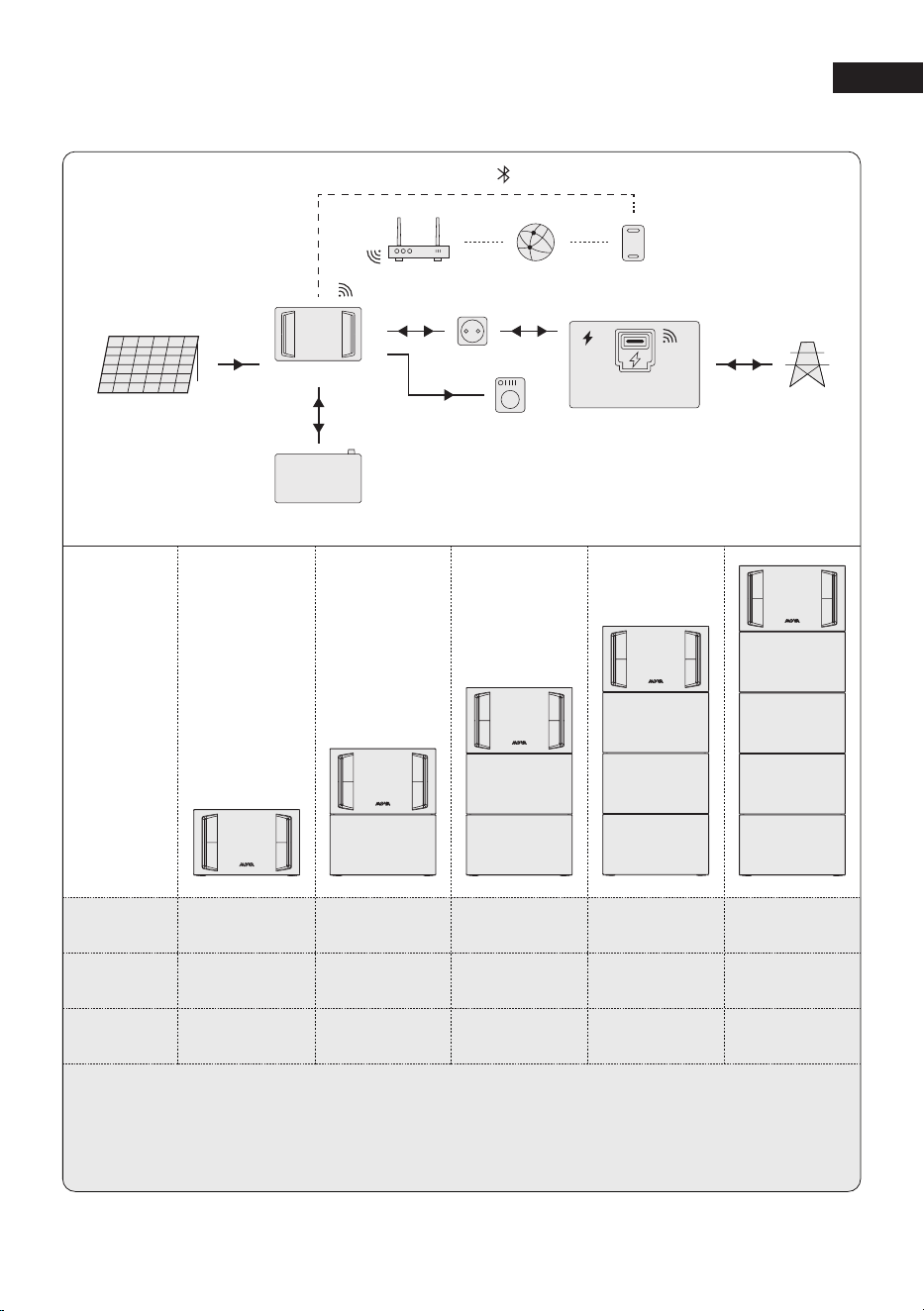
1.5 System Overview
System
Overview
LumeGret
A4000
LumeGret
B4000
System
Capacity
×1 ×1 ×1 ×1 ×1
/ ×1 ×2 ×3 ×4
4.02 KWh 8.04 KWh 12.06 KWh 16.08 KWh 20.10 KWh
Solar Panels PV Input
DC
LumeGret B4000/B2000
AC
AC
AC
Load
Socket
Router Server Phone
Distribution Box
Smart Meter
Power Grid
Wi-Fi
Wi-Fi
Wi-Fi
Bluetooth
LumeGret A4000
The table shows the combination of LumeGret A4000 and LumeGret B4000. Users can also purchase
the expansion battery LumeGret B2000 . The LumeGret B4000 and LumeGret B2000 can be used
individually with the LumeGret A4000, or in combination [e.g., LumeGret A4000 + B4000 + B2000].
However, it can only be expanded with a maximum of 4 expansion batteries.

EN
6
2 Pre-Installation
Before unpacking the unit, carefully inspect the packaging for any signs of damage, such
as holes or cracks, and verify that the model number matches your order. If you notice any
damage or an incorrect model, do not unpack the unit. Contact your dealer or point of purchase
immediately.
2.1
Check the packaging
After unpacking the unit, check if it is intact and complete, and free from any obvious damage.
If any item is missing or damaged, contact your dealer or source of purchase.
2.2
Check the unit
When choosing the position of installation, comply with the following conditions:
·
Choose a proper position to place the LumeGret A4000, leaving at least a 50 mm gap
between the back of the unit and the wall to ensure good heat dissipation.
·
Avoid electromagnetic interference that can compromise the correct operation of electronic
components of the unit.
·
An AC power outlet is needed while finalizing the installation.
·
Do not install it under direct sunlight, or near fire sources or explosives.
·
Ensure the selected location is not at risk from potential hazards such as flooding.
·
The maximum operating altitude is 4,000 meters.
2.3
Check the installation environment and position
·
When carrying the LumeGret A4000, preparations should be made for loading-bearing to
avoid being crushed.
·
When handling the unit, it is recommended that two people lift the LumeGret A4000. Wear
protective gloves to prevent injury.
2.4
Heavy lifting safety
EN
7
3 Installation Steps
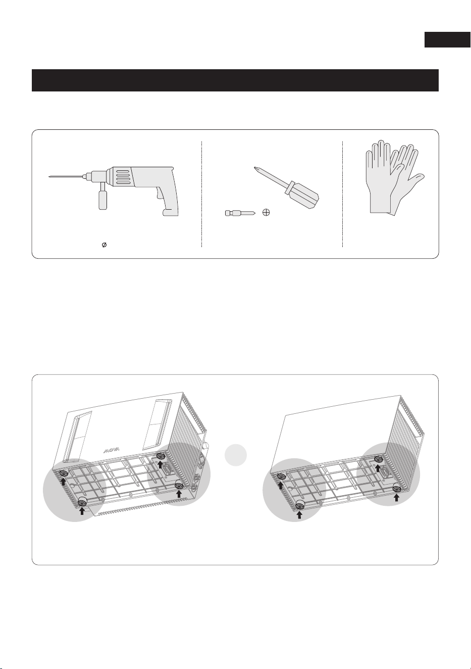
The following tools(Not included) are required before installation:
·
If no expansion battery pack is purchased, the rubber feet are installed on the bottom of the
LumeGret A4000 main unit.
·
If one or more expansion battery are purchased, they are installed at the bottom of the lowest
expansion battery .
Step 1:Install rubber feet
Hammer drill Screwdriver Safety gloves
(PH0, PH1, PH2)8mm
or
LumeGret B4000/B2000LumeGret A4000
EN
8
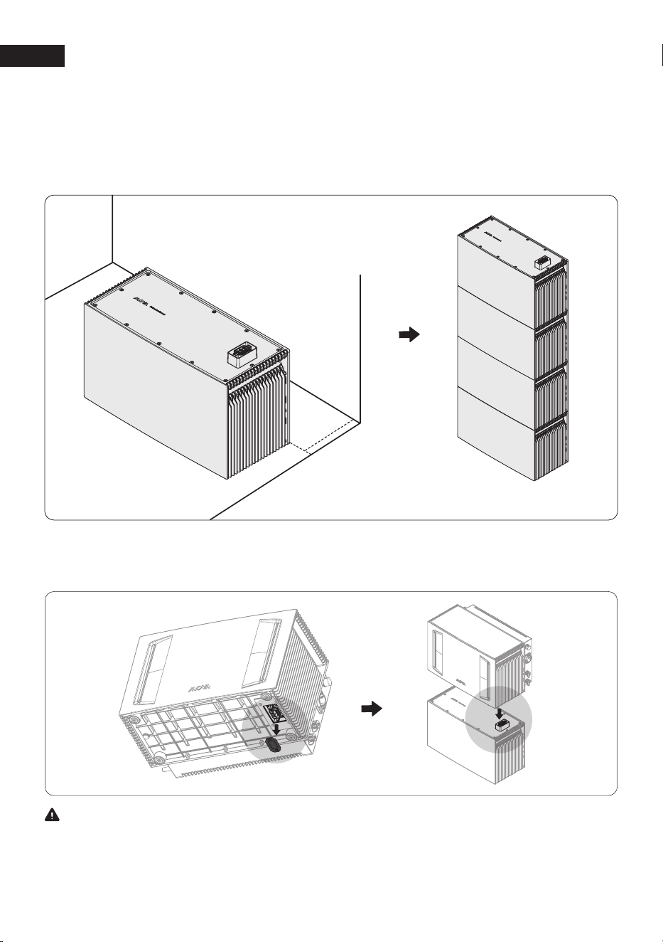
Step 3:Remove the bottom rubber plugs of LumeGret A4000, and stack them at the top
of expansion batteries
Warning
If you didn't buy the expansion batteries seperately, you can place the LumeGret A4000
directly on the ground, but make sure that the rubber plugs of the bottom device should not be
removed!
·
Place expansion battery on the bottom, and keep about 50 mm away from the wall.
·
S
tack all expansion batteries one by one. (Up to 4 Stackable expansion Batteries can be stacked.)
Step 2:Place expansion battery (If you didn't purchase the B4000/B2000 separately, please
skip this step)
50mm
×
4 PCS
EN
9
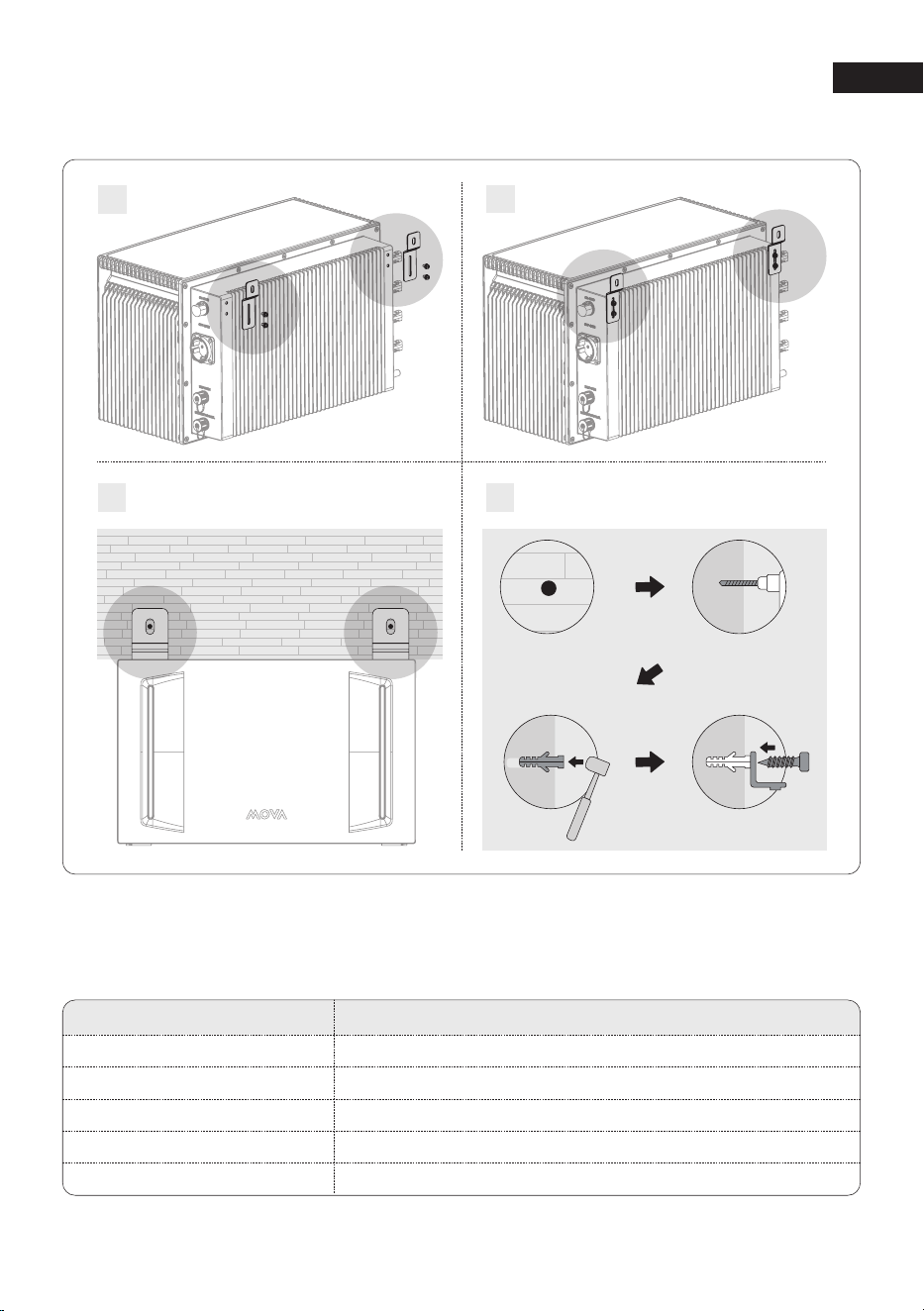
Step 4:Install the Wall Mount Kit
1
2
3
4
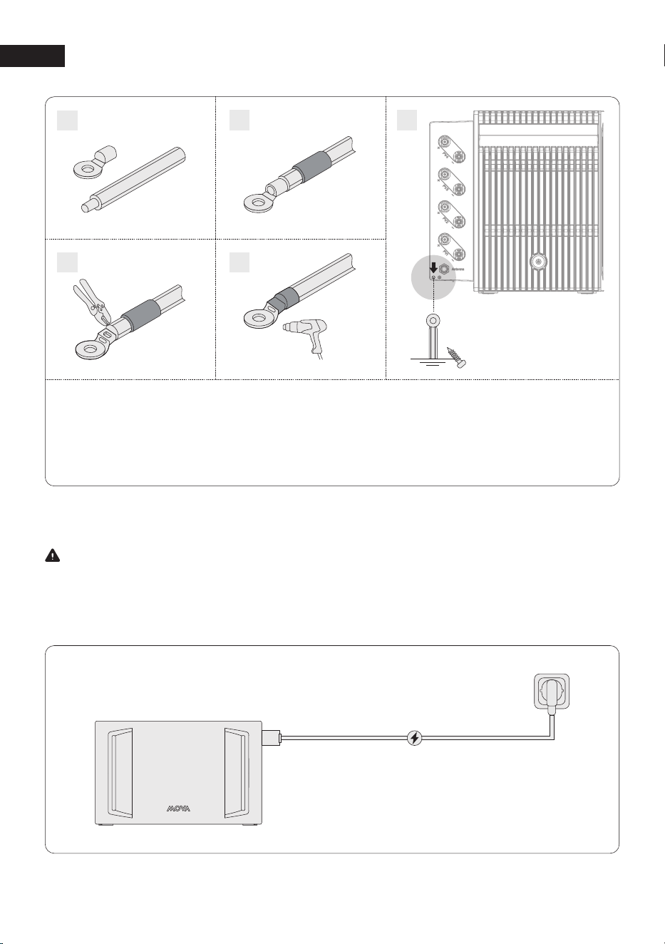
Step 5:Grounding
The following tools and supplies are not included in the package. Ensure that you have them
ready before proceeding with the electrical connections.
Required Supplies
GND cable
Ring terminal
Heat shrink tubing
Heat gun
Phillips screwdriver
Specifications
1 mm2,yellow/green
Suitable for the 1 mm2 GND cable and the M5 screw
Caliber: 8 mm; Length: 25 mm
/
PH2
EN
10
Step 6:Connect to Grid Power via a Home Outlet
Warning
The grid connection must be connected to a grounded electrical outlet or grounding busbar.
Additionally, grounding the product casing via its dedicated grounding terminal is recommended
for enhanced safety. Ensure the device is powered off before installation.
1. Strip the insulation layer of the GND cable.
2. Insert a heat shrink tubing and a ring terminal into the GND cable.
3. Crimp the ring terminal onto the GND cable using a crimper.
4. Wrap the wire crimping area with the heat shrink tubing using a heat gun.
5. Loosen the pre-installed screw and use it to secure the GND cable.
5
1
2
3
4
EN
11
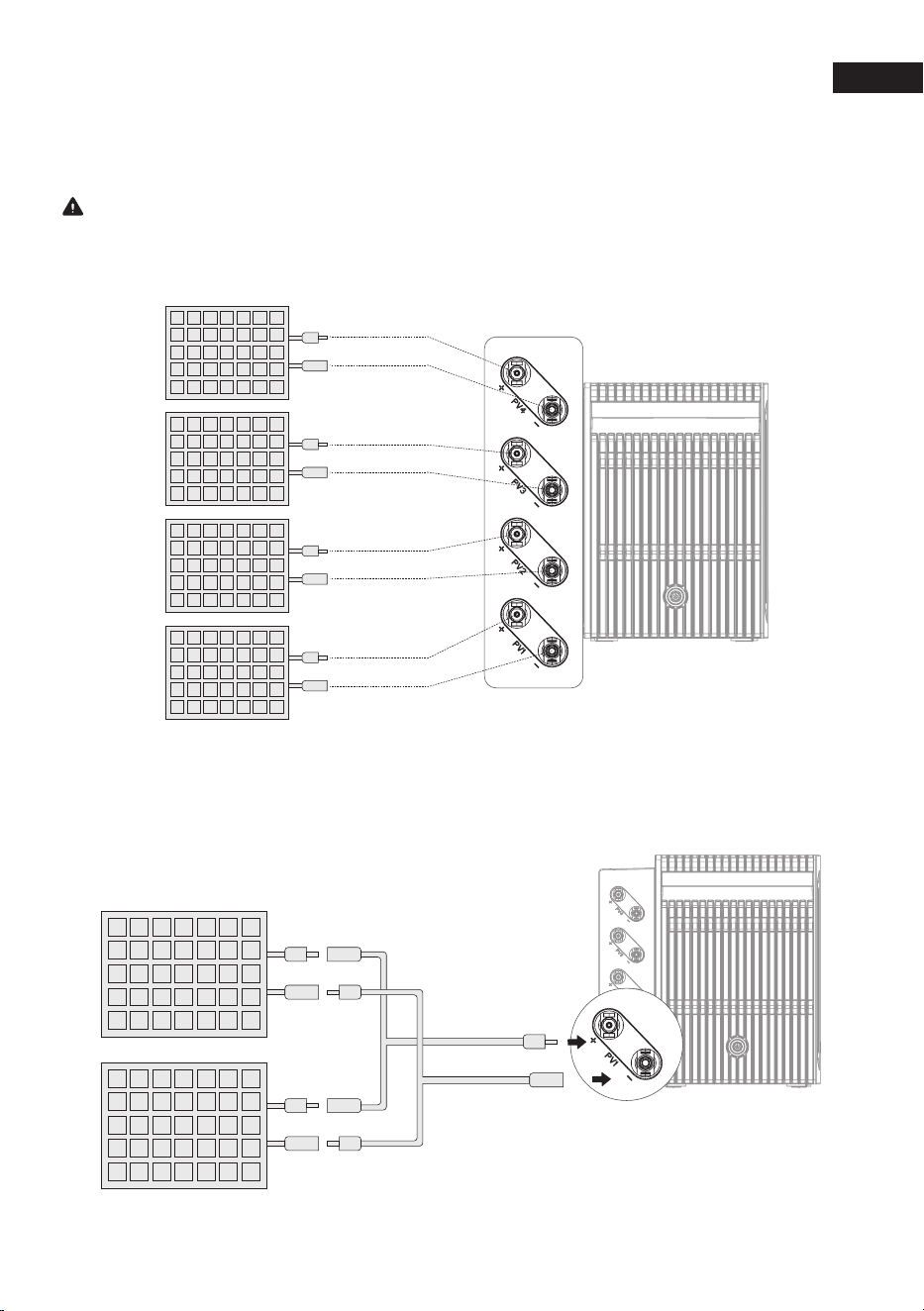
Step 7:Connect to Solar Panels
Solar Panel is not included in the package, it's an optional accessory.
Caution
Never connect the leads of a solar panel to different PV terminals (e.g., gative to PV1-and
positive to PV2+) to prevent short circuits.
Parallel Connection (Up to 8 PV Modules)
Connect every two pv modules to the same set of pv input ports.
PV1 +
PV1 -
PV2 +
PV2 -
PV3 +
PV3 -
PV4 +
PV4 -
EN
12
Step 8: Power On and Settings.
·
Power On: Long press the power button for 3 seconds to power on the device.
·
Bind the Device and Set Up the Internet:
Follow the in-app instructions to bind the device and enjoy smart control from your phone.
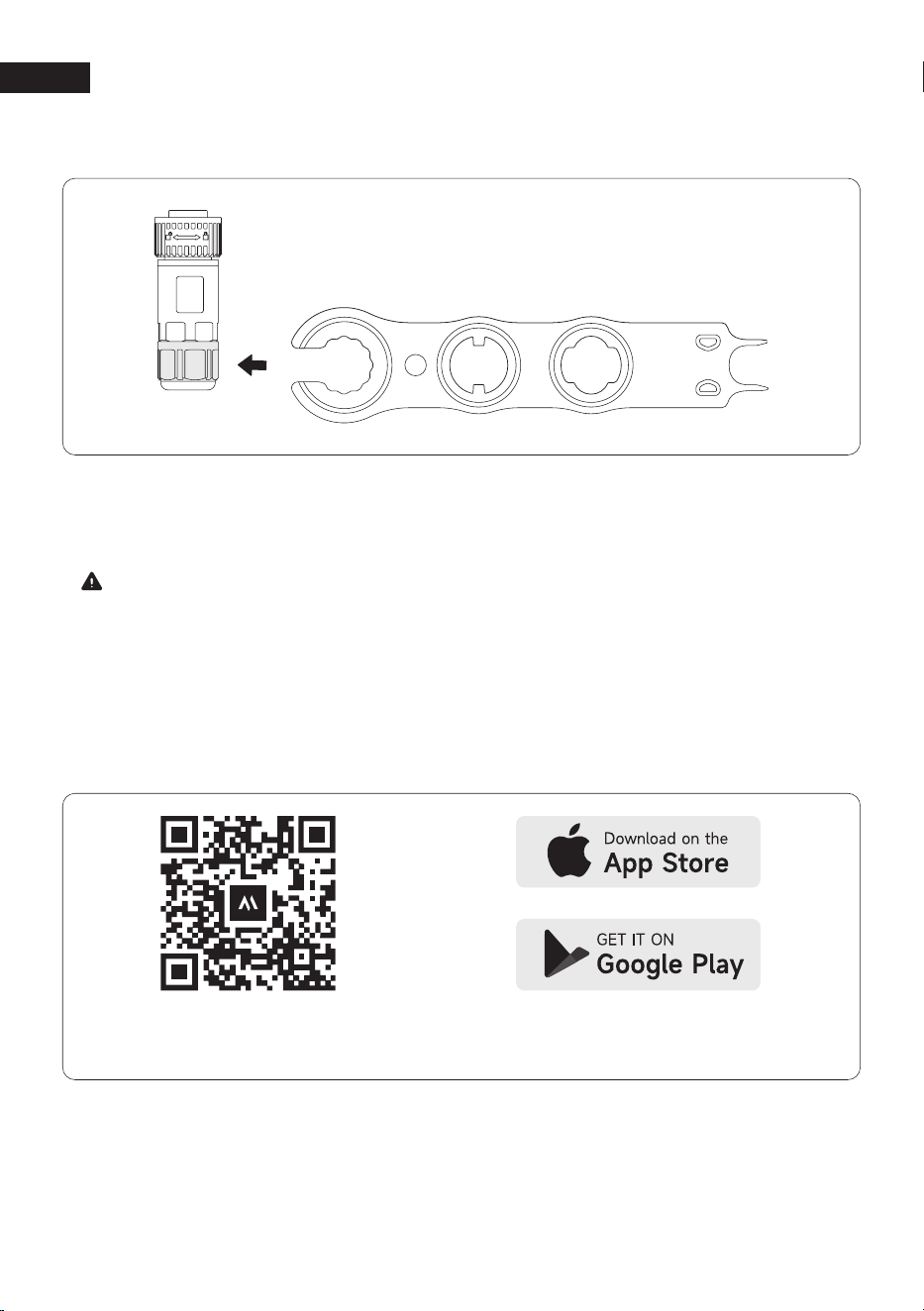
If you need to adjust the PV Connection, dis connect the solar connectors using the PV Wrench.
Scan to download
the MOVAhome APP
Search for the MOVAhome App
in your App store to download it.
·
Download the MOVAhome App:
Scan the QR code or search for the MOVAhome app in your app store to download it.
Then, register an account and log in.
Note:
When the LumeGret A4000 is powered on, the expansion batteries LumeGret B4000/B2000
will automatically activate. Confirm that the battery button light is on.this indicates that the
expansion batteries are powered on.

EN
13
4 Specifications
PV Terminal
Max. PV Input Voltage: 60 VDC
Operation Voltage Range: 16-60 VDC
Max. PV Input Current: 18A*4
Max. PV Short-Circuit Current(ISC): 25A*4
Max. PV Input Power: 3600W
Battery Data
Rechargeable Battery: LFP
Rated Voltage: 51.2V
Rated Power (Single Device): 2000W
Rated Capacity: 4020Wh
AC Output (On-Grid Terminal)
Max AC Output Power: 800W / 2500W
Rated Voltage: L+N+PE,220V/230V,50Hz
Rated Current: 4A / 11A
AC Input (On-Grid Terminal)
AC Input Power: 2500W
Rated AC Input Voltage:
L+N+PE,220V/230V,50Hz
Rated Current: 8.7A
AC Output (Off-Grid Terminal)
Max AC Output Power: 2500W
AC Output Voltage: 230V,50Hz
Max AC Output Current: 11.5A
General Parameters
Communication: WiFi&Bluetooth+RS485
Protective Class: I
Ingress Protection: IP65
Inverter Topology: Isolated
Operating Temperature Range: -20~55℃
Max Altitude: 2000m
Warranty: 10 Years
Dimensions: 493*305*295mm
Net Weight: 48kg
LumeGret A4000
LumeGret B4000 Battery Data
Rechargeable Battery: LFP
Rated Voltage: 51.2V
Rated Power (Single Device): 2000W
Rated Capacity: 4020Wh
Ingress Protection: IP65
Operating Temperature Range: -20~55℃
Warranty: 10 Years
Dimensions: 493*307.7*220mm
Net Weight: 40kg
LumeGret B2000 Battery Data
Rechargeable Battery: LFP
Rated Voltage: 51.2V
Rated Power (Single Device): 1000W
Rated Capacity: 2010Wh
Ingress Protection: IP65
Operating Temperature Range: -20~55℃
Warranty: 10 Years
Dimensions: 493*307.7*220mm
Net Weight: 27kg
Expansion Battery B4000/B2000
(Sold separately)

EN
14
5 EU Declaration of Conformity
Equipment with Wireless Communication Modules
The equipment with wireless communication modules sold in the European market meets the
requirements of the following directives:
·
Radio Equipment Directive 2014/53/EU (RED)
·
Restrictions of Hazardous Substances Directive 2011/65/EU and (EU) 2015/863 (RoHS)
·
Waste Electrical and Electronic Equipment 2012/19/EU
·
Registration, Evaluation, Authorization and Restriction of Chemicals (EC) No1907/2006 (REACH)
Battery
The batteries sold in the European market meets the requirements of the following directives:
·
Electromagnetic compatibility Directive 2014/30/EU (EMC)
·
Battery Directive 2006/66/EC and Amending Directive 2013/56/EU
·
Waste Electrical and Electronic Equipment 2012/19/EU
·
Registration, Evaluation, Authorization and Restriction of Chemicals (EC) No1907/2006 (REACH)

EN
15
6 Warranty Exclusions
In the event of damage related to the causes listed below, no warranty claims will be
acknowledged or accepted. Claims that relate to defects that are caused by the following
factors are not covered by MOVA’s warranty obligations.
1. Can not provide proof of purchase.
2. Force majeure (storm damage, lightning strike, over voltage, fire, thunderstorm, flooding;
social causes such as war, turmoil, government intervention, strikes, embargoes, market
conditions, etc.).
3. Accidental damage, misuse, abuse, non-compliant use, normal wear and tear, theft, loss, or
confiscation.
4. Improper application of electrical supply voltage, current and/or frequency.
5. Improper installation, commissioning, start-up, configuration, or operation (contrary to the
guidance detailed in the installation manual supplied with each product).
6. Inadequate ventilation and circulation resulting in insufficient cooling and natural airflow.
7. Modifications to any part of the product.
8. Unauthorized repair attempts.
9. Products whose serial number sticker or imprint has been removed, defaced or tampered
with.
10. Products purchased from unauthorized dealers/resellers.
11. Free products/rewards/gifts.
12. Products used outside of the purchasing region, and products that are shipped to areas that
are not easily accessible by courier or freight services, such as overseas or remote islands.
13. Cosmetic or superficial defects, dents, marks or scratches, which do not influence the proper
functioning of the product.
14. This limited warranty does not cover any battery cell or product containing a battery cell
unless you fully charge the battery cell within thirty (30) days of receiving the product and
subsequently charge it at least once every 3 months. Failure to do so will void the warranty
for the battery cell and coverage for any associated damage or malfunctions. It is preferable
to fully charge it within seven (7) days of receiving the product.
15. Our warranties are non-transferable from end user to end user.
Furthermore, this limited warranty and related service will not exceed the original cost of the
MOVA product. Please note that these warranty terms and conditions are subject to change
without prior notice. The MOVA Support Team reserves the right to make a final determination
regarding warranty service eligibility, and to determine the appropriate solution, which may
include replacement, repair, or refund, at its sole discretion.