
1 Features
Embedded low-
power KM4 MCU, which can also function as an application processor
Clock rate: 100 MHz
Working voltage: 3.0 V to 3.6 V
Peripherals: seven GPIOs and two universal asynchronous
(UARTs)
Wi-Fi /BT connectivity
802.11b/g/n20
Channels 1 to 14 at 2.4 GHz
Compatible with Bluetooth low energy (BLE) 4.2
power)
WPA and WPA2 security modes
Up to +20 dBm
EIPR
Smart network configuration for Android and iOS devices
FPC IPEX
antenna
Certified by CE, FCC, and SRRC
Working temperature:
1.2 Applications
Intelligent building
Smart household and home appliances
Smart socket and light
Industrial wireless
control
Baby monitor
Network camera
Intelligent bus
WBR1
1
power KM4 MCU, which can also function as an application processor
Clock rate: 100 MHz
Working voltage: 3.0 V to 3.6 V
Peripherals: seven GPIOs and two universal asynchronous
receivers/transmitters
Channels 1 to 14 at 2.4 GHz
Compatible with Bluetooth low energy (BLE) 4.2
(Up to +9dBm
EIPR
WPA and WPA2 security modes
EIPR
output power in 802.11b mode
Smart network configuration for Android and iOS devices
antenna
Certified by CE, FCC, and SRRC
Working temperature:
–20°C to +85°C
Smart household and home appliances
control
WBR1
-IPEX Datasheet
power KM4 MCU, which can also function as an application processor
receivers/transmitters
EIPR
output

1 Feature
2 Module Interfaces
................................
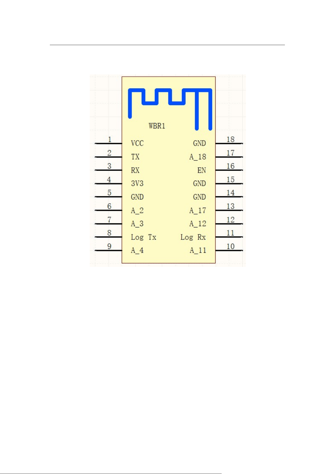
2.1 Dimensions and Footprint
2.2 Interface Pin Definition
3 Electrical Parameters
................................
3.1 Absolute Electrical Parameters
3.2 Electrical Conditions
3.3 RF Current Consumption
3.4 Working Current
................................
4 RF Features
................................
4.1 Basic RF Featu
res
4.2 TX Performance
................................
4.3 RX Performance
................................
5 Antenna Information
................................
5.1 Antenna Type
................................
5.2 Antenna Interference Reduction
6 Packaging Information and Production Instructions
6.1 Mechanical Dimensions
6.2 Recommended PCB Layout
6.3 Production Instructions
6.4 Recommended Oven Temperature Curve
6.5 Storage Conditions
7 MOQ and Packing Information
WBR1
2
Contents
................................
................................
................................
2.1 Dimensions and Footprint
................................
................................
2.2 Interface Pin Definition
................................................................
...........................
................................
................................
................................
3.1 Absolute Electrical Parameters
................................
................................
3.2 Electrical Conditions
................................................................
...............................
3.3 RF Current Consumption
................................
................................
................................
................................
................................
................................
................................
................................
res
................................................................
................................
................................
................................
................................
................................
................................
................................
................................
................................
................................
................................
................................
................................
5.2 Antenna Interference Reduction
................................
................................
6 Packaging Information and Production Instructions
................................
.......................
6.1 Mechanical Dimensions
................................................................
.......................
6.2 Recommended PCB Layout
................................
................................
6.3 Production Instructions
................................................................
.........................
6.4 Recommended Oven Temperature Curve
................................
...........................
6.5 Storage Conditions
................................................................
...............................
7 MOQ and Packing Information
................................................................
.......................
WBR1
-IPEX Datasheet
............ 1
................................
............. 4
................................
...................... 4
...........................
4
................................
........ 6
................................
.............. 6
...............................
6
................................
....................... 7
................................
..... 7
................................
................................
................................
......9
................................
........ 10
................................
........ 10
................................
........... 10
.......................
10
.......................
10
................................
................. 12
.........................
13
...........................
15
...............................
16
.......................
17
................................
................................
................................
................................
................................
................
...................... 8
...............................
8
..... 9

Table 2-1 WBR1-IPEX
interface pins
Table 3-
1 Absolute electrical parameters
Table 3-
2 Normal electrical conditions
Table 3-
3 Power consumption during constant transmission
Table 3-
4 Power consumption during constant receiving
Table 3-5 WBR1-IPEX
working current
Table 4-
1 Basic RF features
Table 4-
2 Performance during constant transmission
Table 4-3 RX sensitivity
................................
Figure 2-1 WBR1-IPEX
front and rear views
Figure 6-1 WBR1-IPEX
mechanical dimensions
Figure 6-2 Side view
................................
Figure 6-3 WBR1-IPEX
pins
Figure 6-
4 Layout of the PCB to which
Figure 6-5 HIC for WBR1-
IPEX
Figure 6-
6 Oven temperature curve
WBR1
3
Tables
interface pins
................................
................................
1 Absolute electrical parameters
................................
................................
2 Normal electrical conditions
................................
................................
3 Power consumption during constant transmission
................................
4 Power consumption during constant receiving
................................
working current
................................
................................
1 Basic RF features
................................................................
..............................
2 Performance during constant transmission
................................
.......................
................................
................................
................................
Figures
front and rear views
................................
................................
mechanical dimensions
................................
...............................
................................
................................
................................
pins
................................................................
..............................
4 Layout of the PCB to which
WBR1-IPEX applies
................................
IPEX
................................................................
.........................
6 Oven temperature curve
................................
................................
WBR1
-IPEX Datasheet
................................
................... 6
................................
............ 8
................................
................. 8
................................
.............. 9
................................
.................... 9
................................
............... 9
..............................
10
.......................
11
................................
..... 11
................................
....... 6
...............................
13
................................
.......... 13
..............................
14
................................
............ 15
.........................
16
................................
.................. 17
2 Module Interfaces
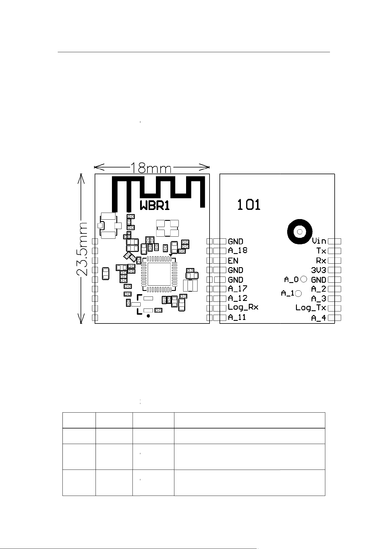
2.1 Dimensions and Footprint
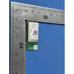
WBR1-IPEX
has two rows of 1
The WBR1-IPEX
dimensions (H x W x D) are 2.9±0.15 mm x 18±0.35 mm x 23.5±0.35
mm. Figure 2-1 shows the
WBR1
Figure 2
2.2 Interface Pin Definition
Table 2
Pin No. Symbol
1 Vin
P
2 TX
I/O
3 RX
I/O
WBR1
4
2 Module Interfaces
2.1 Dimensions and Footprint
has two rows of 1
8 pins (2 x 9) with a 1.5 mm pin spacing.
dimensions (H x W x D) are 2.9±0.15 mm x 18±0.35 mm x 23.5±0.35
WBR1
-IPEX front and rear views.
Figure 2
-1 WBR1-IPEX front and rear views
2.2 Interface Pin Definition
Table 2
-1 WBR1-IPEX interface pins
I/O Type Function
P
UART_TX power conversion pin (5 V or 3.3 V)
I/O
GPIOA_14, UART_TX (user-
side serial
interface)
I/O
GPIOA_13, UART_RX (user-
side serial
interface)
WBR1
-IPEX Datasheet
dimensions (H x W x D) are 2.9±0.15 mm x 18±0.35 mm x 23.5±0.35
UART_TX power conversion pin (5 V or 3.3 V)
side serial
side serial

Pin No. Symbol
4 3V3
P
5 GND
P
6 A_2
I/O
7 A_3
I/O
8 Log_TX
P
9 A_4
I/O
10 A_11
I/O
11 Log_RX
I/O
12 A_12
I/O
13 A_17
I/O
14 GND
P
15 GND
P
16 EN
I/O
17 A_18
I/O
18 GND
P
Note:
P
indicates power supply pins, and
WBR1
5
I/O Type Function
P
Power supply pin (3.3 V)
P
Power supply reference ground pin
I/O
GPIOA_2, hardware PWM pin, which is
connected to pin 18 on the internal IC
I/O
GPIOA_3, hardware PWM pin, which is
connected to pin 19 on the internal IC
P
GPIOA_16, UART_Log_TXD, which is used
for printing the module internal
information
and can be configured as a common GPIO
I/O
GPIOA_4, hardware PWM pin, which is
connected to pin 20 on the internal IC
I/O
GPIOA_11, hardware PWM pin, which is
connected to pin 25 on the internal IC
I/O
GPIOA_15,
UART_Log_RXD, which is used
for printing the module internal information
and can be configured as a common GPIO
I/O
GPIOA_12, hardware PWM pin, which is
connected to pin 26 on the internal IC
I/O
GPIOA_17, hardware PWM pin, which is
conne
cted to pin 38 on the internal IC
P
Power supply reference ground pin
P
Power supply reference ground pin
I/O
Enable pin, which is active at a high level (The
pin has been pulled up and is externally
controllable.)
I/O
GPIOA_18, hardware PWM pin, which is
connected to pin 39 on the internal IC
P
Power supply reference ground pin
indicates power supply pins, and
I/O indicates input/output pins.
WBR1
-IPEX Datasheet
Power supply reference ground pin
GPIOA_2, hardware PWM pin, which is
connected to pin 18 on the internal IC
GPIOA_3, hardware PWM pin, which is
connected to pin 19 on the internal IC
GPIOA_16, UART_Log_TXD, which is used
information
and can be configured as a common GPIO
GPIOA_4, hardware PWM pin, which is
connected to pin 20 on the internal IC
GPIOA_11, hardware PWM pin, which is
connected to pin 25 on the internal IC
UART_Log_RXD, which is used
for printing the module internal information
and can be configured as a common GPIO
GPIOA_12, hardware PWM pin, which is
connected to pin 26 on the internal IC
GPIOA_17, hardware PWM pin, which is
cted to pin 38 on the internal IC
Power supply reference ground pin
Power supply reference ground pin
Enable pin, which is active at a high level (The
pin has been pulled up and is externally
GPIOA_18, hardware PWM pin, which is
connected to pin 39 on the internal IC
Power supply reference ground pin
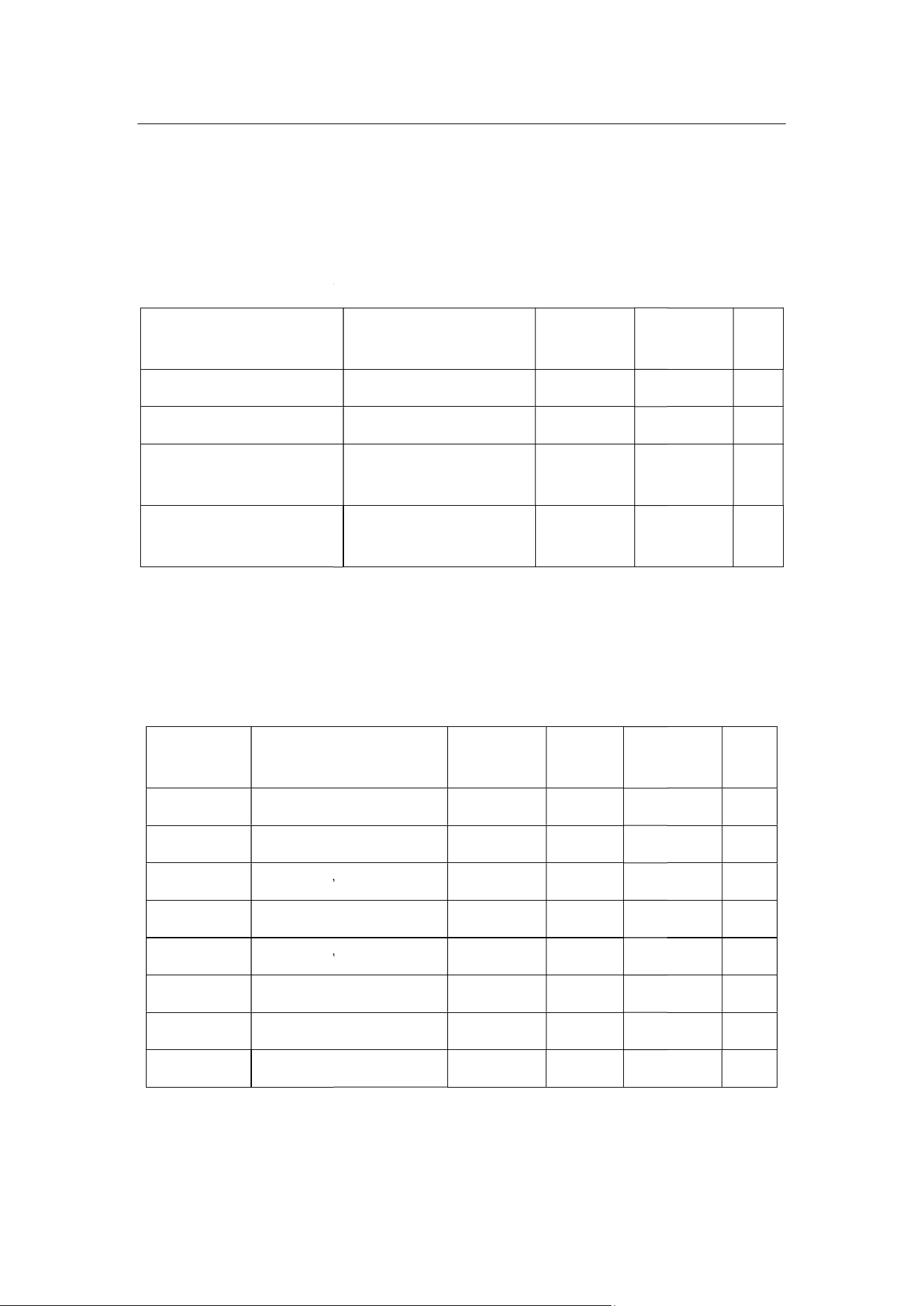
3 Electrical Parameters
3.1 Absolute
Electrical Parameters
Table 3
Parameter
Ts
VDD
Static electricity voltage
(human body model)
Static electricity voltage
(machine model)
3.2 Electrical Conditions
Table 3
Parameter
Description
Ta
Working temperature
VDD Working
voltage
VIL I/O low-
level input
VIH I/O high-
level input
VOL I/O low-
level output
VOH I/O high-
level output
Imax
I/O drive current
Cpad
Input pin capacitance
WBR1
6
3 Electrical Parameters
Electrical Parameters
Table 3
-1 Absolute electrical parameters
Description Minimum
Value
Maximum
Value
Storage temperature –40
105
Power supply voltage –0.3
3.6
Tamb = 25°C N/A 2
Tamb = 25°C N/A
0.5
3.2 Electrical Conditions
Table 3
-2 Normal electrical conditions
Description
Minimum
Value
Typical
Value
Maximum
Value
Working temperature
–20 N/A 85
voltage
3.0 N/A 3.6
level input
N/A N/A 0.8
level input
2.0 N/A N/A
level output
N/A N/A 0.4
level output
2.4 N/A N/A
I/O drive current
N/A N/A 16
Input pin capacitance
N/A 2 N/A
WBR1
-IPEX Datasheet
Maximum
Value
Unit
105
°C
3.6
V
kV
0.5
kV
Maximum
Value
Unit
°C
V
V
V
V
V
mA
pF
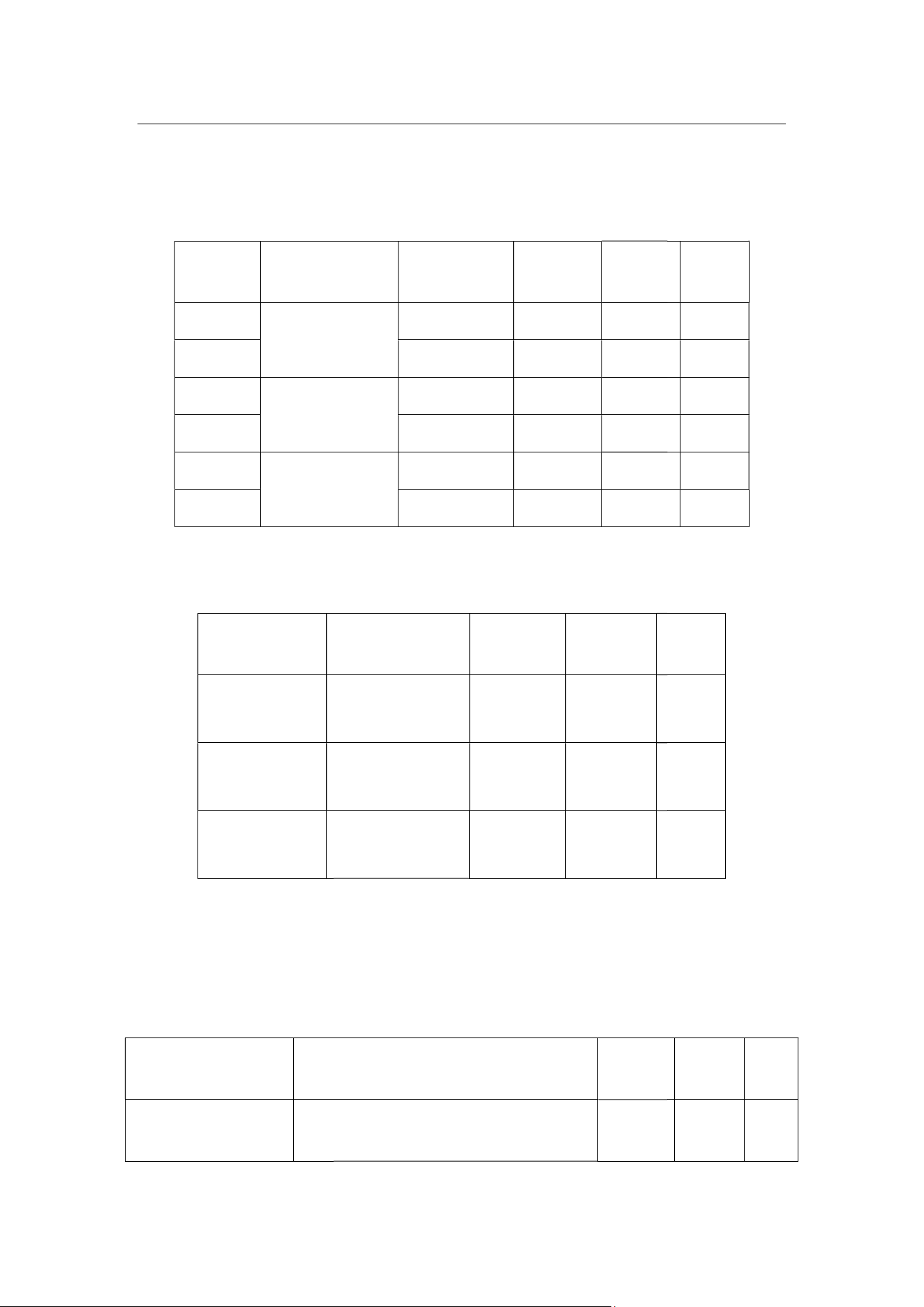
3.3 RF Current Consumption
Table 3-
3 Power consumption during constant transmission
Symbol
Mode
IRF
802.11b
11 Mbit/s
IRF
IRF
802.11g
54 Mbit/s
IRF
IRF
802.11n BW20
MCS7
IRF
Table 3-
4 Power consumption during constant receiving
Symbol
IRF
IRF
IRF
3.4 Working Current
Table 3
Working Mode
EZ
The module is in EZ mode, and the
Wi-
Fi indicator blinks quickly.
WBR1
7
3.3 RF Current Consumption
3 Power consumption during constant transmission
Mode
Power
Typical
Value
Peak
Value
11 Mbit/s
17 dBm 217 268
18 dBm 231 283
54 Mbit/s
15 dBm 159 188
17.5 dBm 177 213
802.11n BW20
13 dBm 145 167
16.5 dBm 165 193
4 Power consumption during constant receiving
Mode Typical
Value
Peak
Value
802.11b
11 Mbit/s
63 65
802.11g
54 Mbit/s
65 67
802.11n
HT20 MCS7
65 67
3.4 Working Current
Table 3
-5 WBR1-IPEX working current
Working Status (Ta = 25°C) Typical
Value
The module is in EZ mode, and the
Fi indicator blinks quickly.
75
WBR1
-IPEX Datasheet
3 Power consumption during constant transmission
Unit
mA
mA
mA
mA
mA
mA
4 Power consumption during constant receiving
Unit
mA
mA
mA
Typical
Peak
Value
Unit
324 mA

Working Mode
Connected and idle
The module is connected to the
network, and the Wi
steady on.
Connected and
operating
The module is connected to the
network, and the Wi
steady on.
Disconnected
The module is disconnected from the
netwo
steady off.
4 RF Features
4.1 Basic RF Features
Parameter
Frequency range
Wi-Fi standard
BLE standard
Data transmission rate
Antenna type
WBR1
8
Working Status (Ta = 25°C) Typical
Value
The module is connected to the
network, and the Wi
-Fi indicator is
steady on.
64
The module is connected to the
network, and the Wi
-Fi indicator is
steady on.
66
The module is disconnected from the
netwo
rk, and the Wi-Fi indicator is
steady off.
66
4.1 Basic RF Features
Table 4-1 Basic RF features
Description
Bluetooth:2402-2480MHz
Wi-Fi:2412-2462MHz
IEEE 802.11b/g/n (channels 1 to 14
,Ch1
US/CA,Ch1-13 for EU/CN)
Bluetooth 4.2
Data transmission rate
802.11b: 1, 2, 5.5, or 11 (Mbit/s)
802.11g: 6, 9, 12, 18, 24, 36, 48, or 54 (Mbit/s)
802.11n: HT20 MCS0 to MCS7
FPC IPEX Antenna,-4.84dBi Gain
WBR1
-IPEX Datasheet
Typical
Peak
Value
Unit
314 mA
305 mA
309 mA
,Ch1
-11 for
802.11g: 6, 9, 12, 18, 24, 36, 48, or 54 (Mbit/s)

4.2 TX Performance
Table 4-
2 Performance during constant transmission
Parameter
Average RF output power,
802.11b CCK mode
Average RF output power,
802.11g OFDM mode
Average RF output power,
802.11n OFDM mode
Average RF output power,
BLE 4.2 1M
Frequency error
EVM under 802.11b CCK, 11 Mbit/s, 17.5
dBm
EVM under 802.11g OFDM, 54 Mbit/s,
dBm
EVM under 802.11n OFDM, MCS7, 13.5
dBm
4.3 RX Performance
Parameter
PER < 8%, 802.11b CCK
mode
PER < 10%, 802.11g OFDM
mode
PER < 10%, 802.11n OFDM
mode
WBR1
9
4.2 TX Performance
2 Performance during constant transmission
Parameter
Minimum
Value
Typical
Value
Maximum
Average RF output power,
1 Mbit/s N/A 17.5
N/A
Average RF output power,
54 Mbit/s N/A 14.5
N/A
Average RF output power,
MCS7 N/A 13.5
N/A
Average RF output power,
6.5
–20 N/A
+20
EVM under 802.11b CCK, 11 Mbit/s, 17.5
–
EVM under 802.11g OFDM, 54 Mbit/s,
14.5 –
EVM under 802.11n OFDM, MCS7, 13.5
–
4.3 RX Performance
Table 4-3 RX sensitivity
Parameter
Minimum
Value
Typical
Value
Maximum
1 Mbit/s N/A –91
N/A
PER < 10%, 802.11g OFDM
54 Mbit/s N/A –75
N/A
PER < 10%, 802.11n OFDM
MCS7 N/A –72
N/A
WBR1
-IPEX Datasheet
Maximum
Value
Unit
N/A
dBm
N/A
dBm
N/A
dBm
dBm
+20
ppm
10 dB
29 dB
30 dB
Maximum
Value
Unit
N/A
dBm
N/A
dBm
N/A
dBm

PER < 10%,
BLE 4.2 mode
5 Antenna Information
5.1 Antenna Type
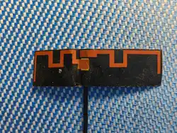
WBR1-IPEX uses a FPC
IPEX
5.2 Antenna Interference Reduction
To ensure optimal Wi-
Fi performance when the Wi
antenna, it is recommended that the antenna be at least 15 mm away from other metal
parts.
6 Packaging Information and Production Instructions
6.1 Mechanical Dimensions
The PCB dimensions (H x W x D) are 0.8±0.1 mm x 18±0.35 mm x 23.5±0.35 mm. Figure
6-1 shows the WBR1-
IPEX
WBR1
10
BLE 4.2 mode
1M N/A -93
N/A
5 Antenna Information
IPEX
antenna with a gain of -4.84 dBi.
5.2 Antenna Interference Reduction
Fi performance when the Wi
-
Fi module uses an onboard PCB
antenna, it is recommended that the antenna be at least 15 mm away from other metal
6 Packaging Information and Production Instructions
6.1 Mechanical Dimensions
The PCB dimensions (H x W x D) are 0.8±0.1 mm x 18±0.35 mm x 23.5±0.35 mm. Figure
IPEX
mechanical dimensions.
WBR1
-IPEX Datasheet
N/A
dBm
Fi module uses an onboard PCB
antenna, it is recommended that the antenna be at least 15 mm away from other metal
6 Packaging Information and Production Instructions
The PCB dimensions (H x W x D) are 0.8±0.1 mm x 18±0.35 mm x 23.5±0.35 mm. Figure
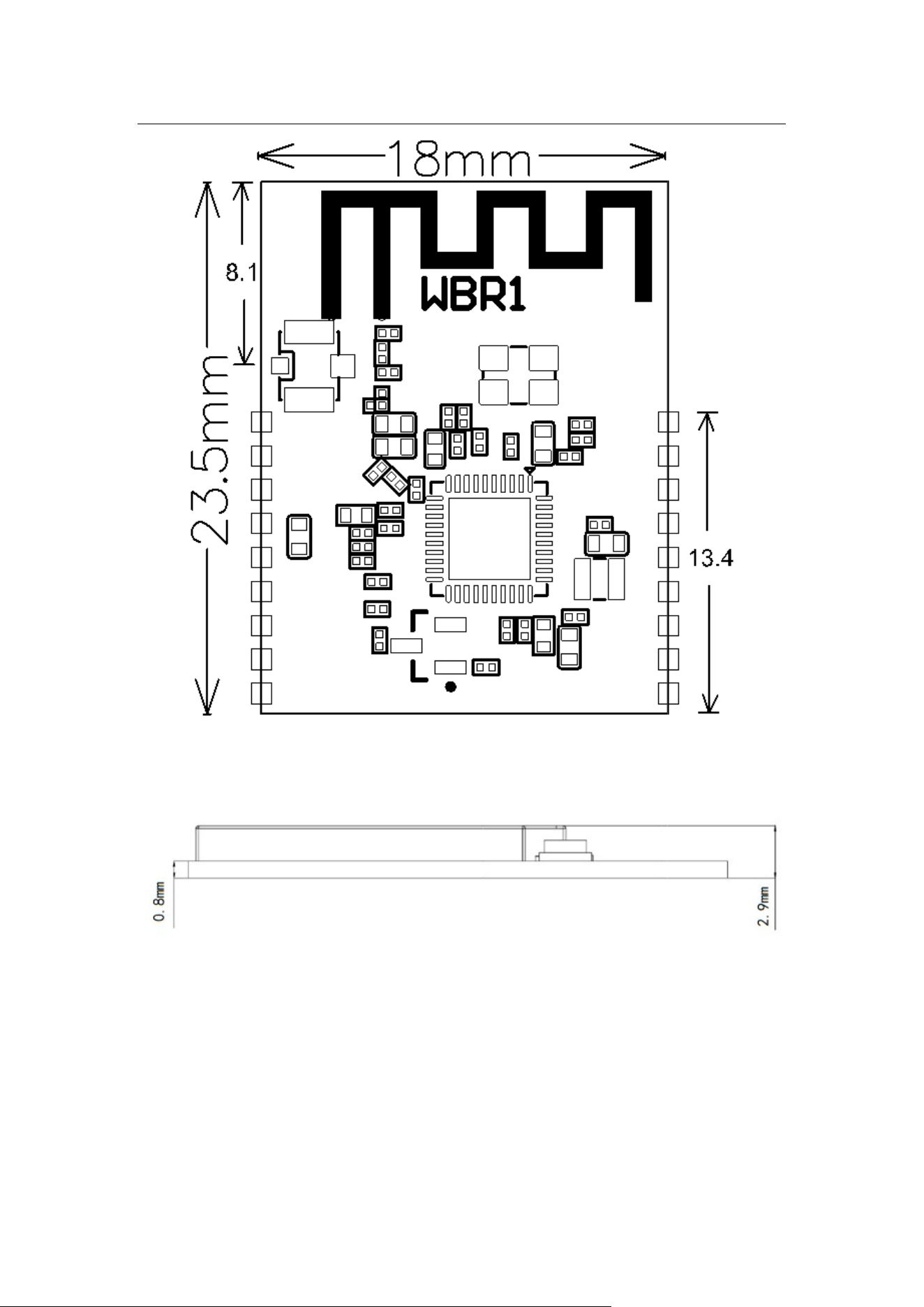
Figure 6
Note:
The default dimensional tolerance is ±0.35 mm. If
clearly specify them in the datasheet after communication.
WBR1
11
Figure 6
-1 WBR1-IPEX mechanical dimensions
Figure 6-2 Side view
The default dimensional tolerance is ±0.35 mm. If
a customer has other requirements,
clearly specify them in the datasheet after communication.
WBR1
-IPEX Datasheet
a customer has other requirements,
6.2 Recommended PCB Layout
WBR1
12
6.2 Recommended PCB Layout
Figure 6-3 WBR1-IPEX pins
WBR1
-IPEX Datasheet
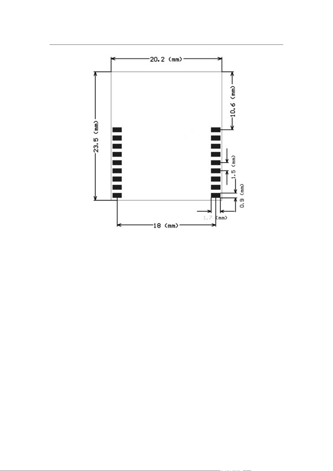
Figure 6-
4 Layout of the PCB to which
6.3 Production Instructions
1.
(1)
SMT placement equipment
i.
Reflow soldering machine
ii.
Automated optical inspection (AOI) equipment
iii.
Nozzle with a 6 mm to 8 mm diameter
(2) Baking equipment
i. Cabinet oven
ii. Anti-
static heat
WBR1
13
4 Layout of the PCB to which
WBR1-IPEX
applies
6.3 Production Instructions
SMT placement equipment
Reflow soldering machine
Automated optical inspection (AOI) equipment
Nozzle with a 6 mm to 8 mm diameter
static heat
-resistant trays
WBR1
-IPEX Datasheet
applies
Use an SMT placement machine to mount the stamp hole module that manufacturer
produces onto the PCB within 24 hours after the module is unpacked and the firmware
is burned. If not, vacuum pack the module again. Bake the module before mounting
it onto the PCB.
iii. Anti-
static heat
2.
Storage conditions for a delivered module are as
(1) The moisture-
proof bag is placed in an environment where the temperature is
below 30°C and the relative humidity is lower than 70%.
(2)
The shelf life of a dry
product is packaged and sealed.
(3) The p
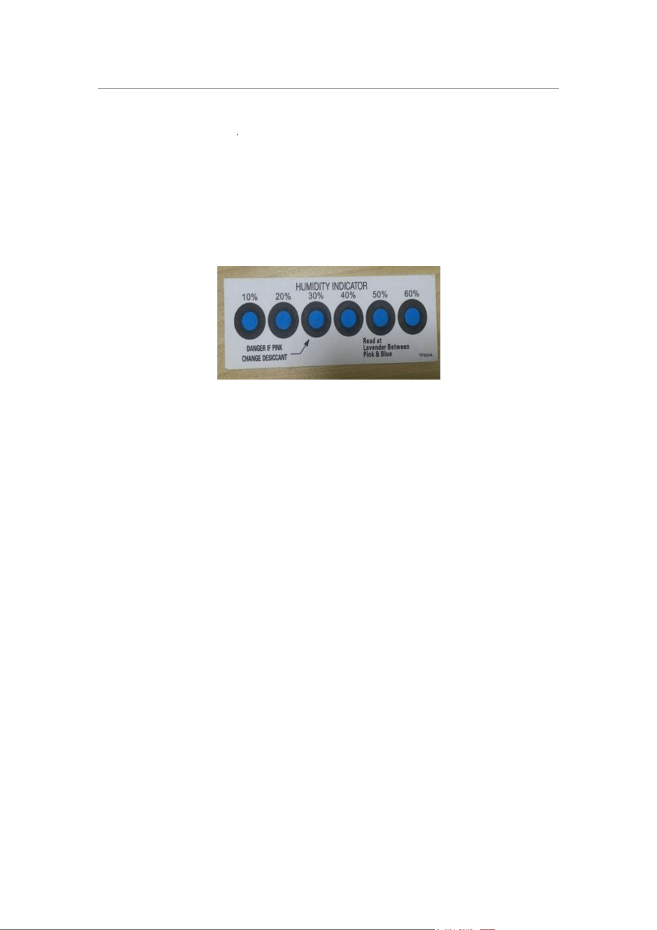
ackage contains a humidity indicator card (HIC).
3.
Bake a module based on HIC status as follows when you unpack the module
package:
(1)
If the 30%, 40%, and 50% circles are blue, bake the module for 2 consecutive
hours.
(2) If the 30%
circle is pink, bake the module for 4 consecutive hours.
(3)
If the 30% and 40% circles are pink, bake the module for 6 consecutive hours.
(4)
If the 30%, 40%, and 50% circles are pink, bake the module for 12 consecutive
hours.
4. Baking settings:
(1)
Baking temperature
(2)
Alarm temperature: 130°C
(3)
SMT placement ready temperature after natural cooling: < 36°C
(4)
Number of drying times: 1
(5)
Rebaking condition: The module is not soldered within 12 hours after baking.
5.
Do not use SMT to process modules that have been unpacked for over three months.
Electroless nickel immersion gold (ENIG) is used for the PCBs. If the solder pads are
exposed to the air for over three months, they will be oxidized severely and dry joints
WBR1
14
static heat
-resistant gloves
Storage conditions for a delivered module are as
follows:
proof bag is placed in an environment where the temperature is
below 30°C and the relative humidity is lower than 70%.
The shelf life of a dry
-
packaged product is six months from the date when the
product is packaged and sealed.
ackage contains a humidity indicator card (HIC).
Figure 6-5 HIC for WBR1-IPEX
Bake a module based on HIC status as follows when you unpack the module
If the 30%, 40%, and 50% circles are blue, bake the module for 2 consecutive
circle is pink, bake the module for 4 consecutive hours.
If the 30% and 40% circles are pink, bake the module for 6 consecutive hours.
If the 30%, 40%, and 50% circles are pink, bake the module for 12 consecutive
Baking temperature
: 125±5°C
Alarm temperature: 130°C
SMT placement ready temperature after natural cooling: < 36°C
Number of drying times: 1
Rebaking condition: The module is not soldered within 12 hours after baking.
Do not use SMT to process modules that have been unpacked for over three months.
Electroless nickel immersion gold (ENIG) is used for the PCBs. If the solder pads are
exposed to the air for over three months, they will be oxidized severely and dry joints
WBR1
-IPEX Datasheet
proof bag is placed in an environment where the temperature is
packaged product is six months from the date when the
Bake a module based on HIC status as follows when you unpack the module
If the 30%, 40%, and 50% circles are blue, bake the module for 2 consecutive
circle is pink, bake the module for 4 consecutive hours.
If the 30% and 40% circles are pink, bake the module for 6 consecutive hours.
If the 30%, 40%, and 50% circles are pink, bake the module for 12 consecutive
Rebaking condition: The module is not soldered within 12 hours after baking.
Do not use SMT to process modules that have been unpacked for over three months.
Electroless nickel immersion gold (ENIG) is used for the PCBs. If the solder pads are
exposed to the air for over three months, they will be oxidized severely and dry joints
o
6.
Before SMT placement, take electrostatic discharge (ESD) protective measures.
7.
To reduce the reflow defect rate, draw 10% of the products for visual inspection and
AOI before f
irst SMT placement to determine a proper oven temperature and
component placement method. Draw 5 to 10 modules every hour from subsequent
batches for visual inspection and AOI.
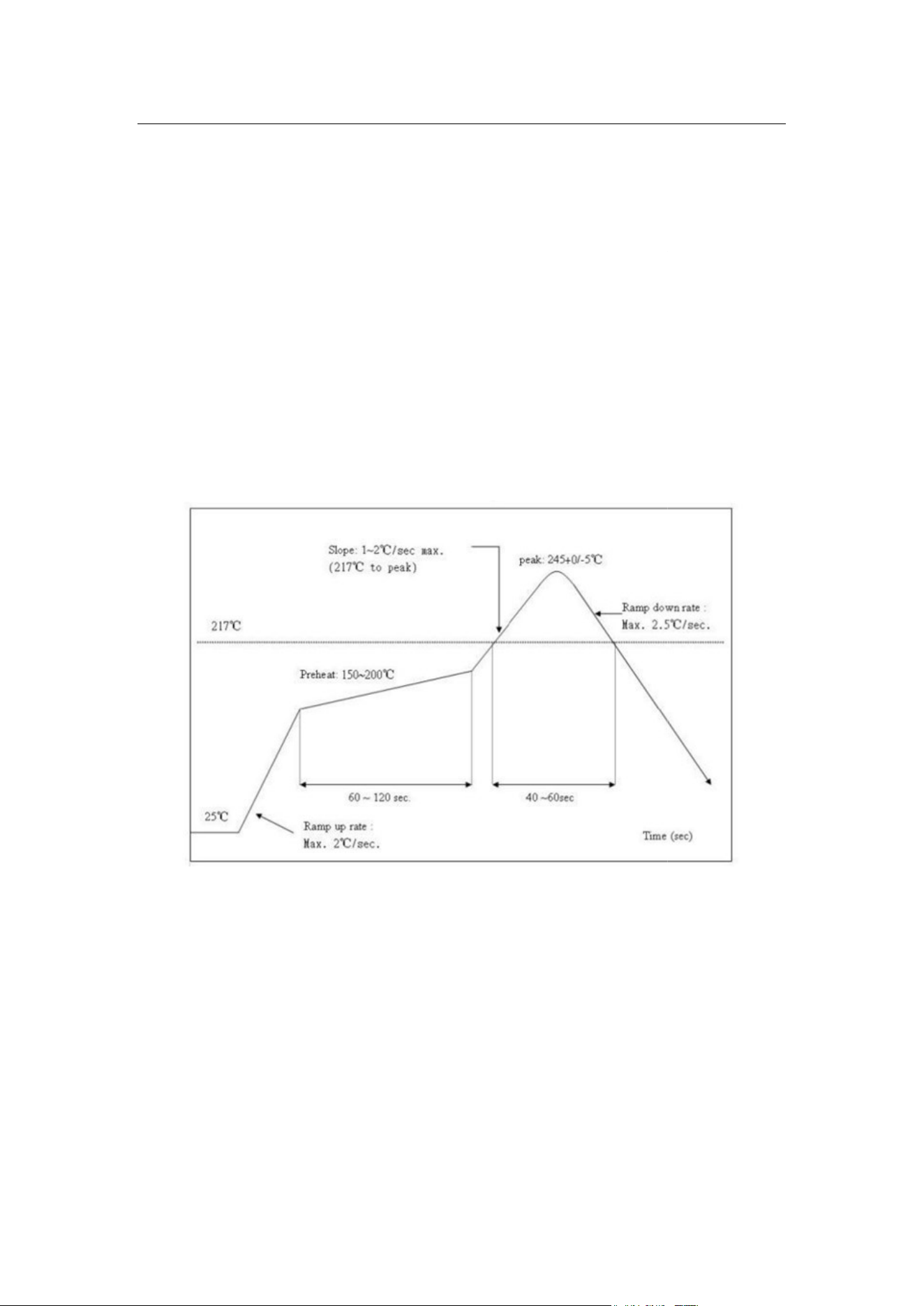
6.4 Recommended Oven Temperature Curve
Perform SMT placement based on the
highest temperature is 245°C.
Based on the IPC/JEDEC standard, perform reflow soldering on a module at most twice.
Figure 6
WBR1
15
Before SMT placement, take electrostatic discharge (ESD) protective measures.
To reduce the reflow defect rate, draw 10% of the products for visual inspection and
irst SMT placement to determine a proper oven temperature and
component placement method. Draw 5 to 10 modules every hour from subsequent
batches for visual inspection and AOI.
6.4 Recommended Oven Temperature Curve
Perform SMT placement based on the
following reflow oven temperature curve. The
highest temperature is 245°C.
Based on the IPC/JEDEC standard, perform reflow soldering on a module at most twice.
Figure 6
-6 Oven temperature curve
WBR1
-IPEX Datasheet
Before SMT placement, take electrostatic discharge (ESD) protective measures.
To reduce the reflow defect rate, draw 10% of the products for visual inspection and
irst SMT placement to determine a proper oven temperature and
component placement method. Draw 5 to 10 modules every hour from subsequent
following reflow oven temperature curve. The
Based on the IPC/JEDEC standard, perform reflow soldering on a module at most twice.
r solder skips may occur. Manufacturer is not liable for such problems and consequences.
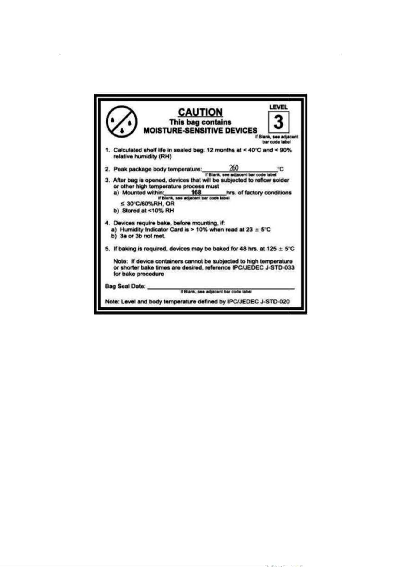
6.5 Storage Conditions
WBR1
16
6.5 Storage Conditions
WBR1
-IPEX Datasheet

7 MOQ and Packing
Product number MOQ(
pcs
WBR1-IPEX 4000
WBR1
17
7 MOQ and Packing
Information
pcs
) Shipping
packaging
method
Modules per reel
(pcs)
Tape reel 1000
WBR1
-IPEX Datasheet
Packaging reels
per box (reels)
4

8 Appendix: Statement
Federal Communications Commission (FCC) Declaration ofConformity
FCC Caution: Any changes or modifications not expresslyapproved by the party
responsible for compliance could void the user'sauthority to operate this equipment.
This device complies with Part 15 of the FCC Rules.Operation is subject to the following
two
conditions: (1) This device may notcause harmful interference, and (2) this device
must accept any interferencereceived, including interference that may cause undesired
operation.
Note:
This equipment has been tested and found to complywith the limits for
digital device, pursuant to part 15 of the FCC Rules.These limits are designed to provide
reasonable protection against harmfulinterference in a residential installation. This
equipment generates, uses andcan radiate radio frequency energy and, i
and used inaccordance with the instructions, may cause harmful interference to
radiocommunications. However, there is no guarantee that interference will notoccur in a
particular installation. If this equipment does cause harmfulinterferenc
television reception, which can be determined byturning the equipment off and on, the
user is encouraged to try to correct theinterference by one or more of the following
measures:
—
Reorient or relocate the receiving antenna.
—Increase the se
paration between the equipment and receiver.
—
Connect the equipment into an outlet on a circuit different from that to which
the receiver is connected.
—
Consult the dealer or an experienced radio/TV technician for help.
Radiation Exposure Statement
This
equipment complies with FCC radiation exposure limits set forth for an
uncontrolledrolled environment. This equipment should be installed and operated with
minimumdistance 20cm between the radiator and your body.
Important Note
This radio module must not i
radios in host system
except in accordance with FCC multi
procedures.A
dditional testing and equipment authorization may berequired to operating
simultaneously with other radio
The availability of some specific channels and/or operational frequency bandsare country
dependent and are firmware programmed at the factory to matchthe intended
destination.The firmware setting is not accessible by the end user.
WBR1
18
Federal Communications Commission (FCC) Declaration ofConformity
FCC Caution: Any changes or modifications not expresslyapproved by the party
responsible for compliance could void the user'sauthority to operate this equipment.
This device complies with Part 15 of the FCC Rules.Operation is subject to the following
conditions: (1) This device may notcause harmful interference, and (2) this device
must accept any interferencereceived, including interference that may cause undesired
This equipment has been tested and found to complywith the limits for
digital device, pursuant to part 15 of the FCC Rules.These limits are designed to provide
reasonable protection against harmfulinterference in a residential installation. This
equipment generates, uses andcan radiate radio frequency energy and, i
and used inaccordance with the instructions, may cause harmful interference to
radiocommunications. However, there is no guarantee that interference will notoccur in a
particular installation. If this equipment does cause harmfulinterferenc
television reception, which can be determined byturning the equipment off and on, the
user is encouraged to try to correct theinterference by one or more of the following
Reorient or relocate the receiving antenna.
paration between the equipment and receiver.
Connect the equipment into an outlet on a circuit different from that to which
Consult the dealer or an experienced radio/TV technician for help.
Radiation Exposure Statement
equipment complies with FCC radiation exposure limits set forth for an
uncontrolledrolled environment. This equipment should be installed and operated with
minimumdistance 20cm between the radiator and your body.
This radio module must not i
nstalled to co-
locate and operating simultaneously withother
except in accordance with FCC multi
-
transmitter product
dditional testing and equipment authorization may berequired to operating
simultaneously with other radio
.
The availability of some specific channels and/or operational frequency bandsare country
dependent and are firmware programmed at the factory to matchthe intended
destination.The firmware setting is not accessible by the end user.
WBR1
-IPEX Datasheet
Federal Communications Commission (FCC) Declaration ofConformity
FCC Caution: Any changes or modifications not expresslyapproved by the party
responsible for compliance could void the user'sauthority to operate this equipment.
This device complies with Part 15 of the FCC Rules.Operation is subject to the following
conditions: (1) This device may notcause harmful interference, and (2) this device
must accept any interferencereceived, including interference that may cause undesired
This equipment has been tested and found to complywith the limits for
a Class B
digital device, pursuant to part 15 of the FCC Rules.These limits are designed to provide
reasonable protection against harmfulinterference in a residential installation. This
equipment generates, uses andcan radiate radio frequency energy and, i
f not installed
and used inaccordance with the instructions, may cause harmful interference to
radiocommunications. However, there is no guarantee that interference will notoccur in a
particular installation. If this equipment does cause harmfulinterferenc
e to radio or
television reception, which can be determined byturning the equipment off and on, the
user is encouraged to try to correct theinterference by one or more of the following
Connect the equipment into an outlet on a circuit different from that to which
equipment complies with FCC radiation exposure limits set forth for an
uncontrolledrolled environment. This equipment should be installed and operated with
locate and operating simultaneously withother
transmitter product
dditional testing and equipment authorization may berequired to operating
The availability of some specific channels and/or operational frequency bandsare country
dependent and are firmware programmed at the factory to matchthe intended

The host product manufa
cturer is responsible for compliance to any other FCC rules that
apply to the host not covered by the modular transmitter grant of certification. The final
host product still requires Part 15 Subpart B compliance testing with the modular
transmitter installed.
The end user manual shall include all required regulatory information/warning as shown in
this manual, including: This product must be installed and operated with a minimum
distance of 20 cm between the radiator and user body.
This device is intended only for OEM integrators under the following conditions:
1) The antenna must be in
stalled such that 20cm is maintained between the antenna and
users, and
2) The transmitter module may not be co
As long as 2 conditions above are met, further transmitter test will not be required.
However, th
eOEM integrator is still responsible for testing their end
additional compliancerequirements required with this module installed.
WBR1
19
cturer is responsible for compliance to any other FCC rules that
apply to the host not covered by the modular transmitter grant of certification. The final
host product still requires Part 15 Subpart B compliance testing with the modular
The end user manual shall include all required regulatory information/warning as shown in
this manual, including: This product must be installed and operated with a minimum
distance of 20 cm between the radiator and user body.
This device is intended only for OEM integrators under the following conditions:
stalled such that 20cm is maintained between the antenna and
2) The transmitter module may not be co
-
located with any other transmitter or antenna.
As long as 2 conditions above are met, further transmitter test will not be required.
eOEM integrator is still responsible for testing their end
-
product for any
additional compliancerequirements required with this module installed.
WBR1
-IPEX Datasheet
cturer is responsible for compliance to any other FCC rules that
apply to the host not covered by the modular transmitter grant of certification. The final
host product still requires Part 15 Subpart B compliance testing with the modular
The end user manual shall include all required regulatory information/warning as shown in
this manual, including: This product must be installed and operated with a minimum
This device is intended only for OEM integrators under the following conditions:
stalled such that 20cm is maintained between the antenna and
located with any other transmitter or antenna.
As long as 2 conditions above are met, further transmitter test will not be required.
product for any
This device have got a FCC ID:2BUU5CH. The final end product must be labeled in a visible
area with the following: "Contains FCC ID:2BUU5CH".