WS8475
LoRa Uart Module
Data Sheet
Support 850-930MHz frequency band.
Support transparent transmission, fixed-point transmission, broadcast transmission, channel monitoring and other
functions.
Support deep sleep, in which the power consumption of the whole machine is less than 2UA;
Support multi-level data transmission rate of 2.4k~62.5kbps
Supports multiple levels of baud rate from 1200 bps to 256000 bps.
The maximum supported packet length is 246 bytes.
Support random encryption of data in the air
Support LBT function
Support relay function
Support packet RSSI and channel detection RSSI
Support 1K data cache.
The module supports 81 channels.
Support 3.0~5.5V power supply, and power supply greater than 3.5V can ensure the best performance.
Industrial standard design, supporting long-term use at-40 ~+85℃
Dual antennas are optional (IPEX/ stamp hole) for integration.

Silent Smart Technology Co., Ltd.
2 / 35
Document information
product model
WS8475
Product overview
Uart Module
Document type
Data sheet
Document number
Document version
V3.0
2025.06.18
Document version update
serial
number
version
number
Revised content
Revision date
Reviser
one
v1.0
Initial version
2024.12.17
SQ
2
v2.0
Adjust RF-related configuration parameters
2025.02.12
SQ
three
v2.1
Modify parameter description
2025.03.26
SQ
four
v2.2
Modify the default parameter description and send the
data sequence diagram.
2025.04.19
SQ
five
v3.0
Add AT command configuration and modify hardware
parameters.
2025.06.18
SQ/LP

Silent Smart Technology Co., Ltd.
3 / 35
catalogue
WS8475..........................................................................................................................................................................................................1
1 product overview .......................................................................................................................................................................................5
1.1 Product introduction .......................................................................................................................................................................5
1.2 Features and functions ................................................................................................................................................................... 5
1.3 Application scenarios ..................................................................................................................................................................... 5
2-pin definition .............................................................................................................................................................................................6
3 Hardware design ....................................................................................................................................................................................... 7
4 function description...................................................................................................................................................................................7
4.1 Mode Description ...........................................................................................................................................................................7
4.1.1 Transmission Mode (Mode 0) .............................................................................................................................................8
4.1.1.1 transparent transmission function ............................................................................................................................ 8
4.1.1.2 Broadcasting and Monitoring Functions ..................................................................................................................9
4.1.1.3 fixed-point transmission function ............................................................................................................................ 9
4.1.1.4 relay transmission function ...................................................................................................................................... 9
4.1.1.5 AT configuration function ...................................................................................................................................... 10
4.1.2 WOR mode (modes 1 and 2) .............................................................................................................................................10
4.1.3 Configuration, Sleep Mode (Mode 3) ............................................................................................................................... 10
4.1.3.1 sleep mode ..............................................................................................................................................................11
4.1.3.2 parameter configuration ......................................................................................................................................... 11
4.1.3.2.1 Configuration and configuration in sleep mode ..........................................................................................11
4.1.3.2.2 Configuration in transmission mode ........................................................................................................... 11
4.2 Module status indication .............................................................................................................................................................. 11
4.2.1 receiving data AUX status indication ................................................................................................................................12
4.2.2 Send data AUX status indication ...................................................................................................................................... 12
4.2.3 Power-on AUX status indication .......................................................................................................................................12
4.2.4 AT command resets AUX status indication. ......................................................................................................................13
4.3 Restore factory settings ................................................................................................................................................................13
4.4 factory default parameters ............................................................................................................................................................13
5 parameter configuration .......................................................................................................................................................................... 14
5.1 register configuration ................................................................................................................................................................... 14
5.1.1 Introduction to Configuration Instructions ....................................................................................................................... 14
5.1.2 Configuration Register Description .................................................................................................................................. 15
5.2 AT command configuration ..........................................................................................................................................................17
5.2.1 list of at instructions ..........................................................................................................................................................18
5.2.2 Detailed explanation of AT instruction ............................................................................................................................. 19
5.2.2.1 test instruction AT.................................................................................................................................................. 19
5.2.2.2 echo control instruction ATE..................................................................................................................................20
5.2.2.3 reset command AT+RST........................................................................................................................................ 20
5.2.2.4 restore factory setting instruction AT+RESTORE. ................................................................................................ 21
5.2.2.5 view version information instruction AT+GMR. ................................................................................................... 21
5.2.2.6 serial port operation instruction AT+UART...........................................................................................................21
5.2.2.7 channel operation instruction AT+CHAN ..............................................................................................................22

Silent Smart Technology Co., Ltd.
4 / 35
5.2.2.8 wireless airspeed operation command AT+RATE................................................................................................. 23
5.2.2.9 wireless transmit power operation instruction AT+PWR.......................................................................................24
5.2.2.10 packet RSSI operation instruction AT+PKTRSSI ................................................................................................24
5.2.2.11 real-time RSSI operation instruction AT+RSSI................................................................................................... 25
5.2.2.12 WOR periodic configuration instruction AT+WOR ............................................................................................ 25
5.2.2.13 lbt operation instruction AT+LBT ........................................................................................................................26
5.2.2.14 preamble detection enable operation instruction AT+LPWRPREAM.................................................................27
5.2.2.15 relay enable operation instruction AT+RELAY....................................................................................................27
5.2.2.16 transmission mode operation instruction AT+TRANSMOD ...............................................................................28
5.2.2.17 wireless key operation instruction AT+KEY ....................................................................................................... 28
5.2.2.18 network ID configuration instruction AT+NETID ...............................................................................................29
5.2.2.19 wireless communication address configuration instruction AT+ADDR ..............................................................29
5.2.2.20 channel current RSSI scanning configuration instruction AT+SCAN. ................................................................30
5.2.2.21 exits configuration mode command AT+EXIT.................................................................................................... 30
6 Electrical and other parameters ...............................................................................................................................................................31
6.1 Limit parameters .......................................................................................................................................................................... 31
6.2 Working parameters ..................................................................................................................................................................... 31
6.3 RF performance parameters ......................................................................................................................................................... 31
6.4 package size ................................................................................................................................................................................. 32
7 package size ............................................................................................................................................................................................ 33
8 production guidance ................................................................................................................................................................................34
8.1 reflow soldering curve................................................................................................................................................................. 34
8.2 reflow soldering temperature and time ........................................................................................................................................ 34
9 contact information ................................................................................................................................................................................. 35

Silent Smart Technology Co., Ltd.
5 / 35
1 Product overview
1.1 Product introduction
WS8475 is a UART wireless LoRa data transmission module designed and produced by Chengdu Silent Communication
Technology Co., Ltd. and supporting multiple frequency bands. It is designed with high-performance MCU+Transceiver. The module
supports low power consumption, and the user's single packet length is 246 bytes. Support fixed-point transmission, transparent
transmission, broadcast transmission, WOR transceiver and other functions.
WS8475 supports random encryption, and every time the same data is sent, different data is captured in the air. Supporting Lora
spread spectrum technology, Lora direct sequence spread spectrum technology has the advantages of longer communication distance,
strong anti-interference ability and strong confidentiality.
1.2 Characteristic function
Characteristic function
The measured communication distance is 5km.
It supports advanced LoRa modulation mode and has the advantage of long-distance anti-interference.
Support license-free ISM 433MHz frequency band, support 470MHz meter reading frequency band.
Support transparent transmission, fixed-point transmission, broadcast transmission, channel monitoring, low-power reception and
other functions.
Support deep sleep. In this mode, the power consumption of the whole machine is about < <2uA;;
Support multi-level data transmission rate of 2.4 k~62.5kbps.
Support 1200 ~ 25600bps serial baud rate.
The length of supported subpackages is 246 bytes.
Support random encryption of air data to ensure that the same user data is different encrypted data after being captured in the air for
many times.
Support LBT function
Wide voltage working range: 3.0V~5.5V to support various battery application scenarios.
Industrial standard design, supporting long-term use at-40 ~+85℃
Dual antennas are optional (IPEX/ stamp hole) for integration.
1.3 Application scenario
Application scenario
Street lamp control
environmental monitoring
Intelligent parking lot sensor
Smart agriculture sensor
Industrial sensor, remote controller
Smart home
Silent Smart Technology Co., Ltd.
6 / 35
Wireless alarm safety system
Building automation solution
Health care products
Advanced meter reading architecture (AMI)
2
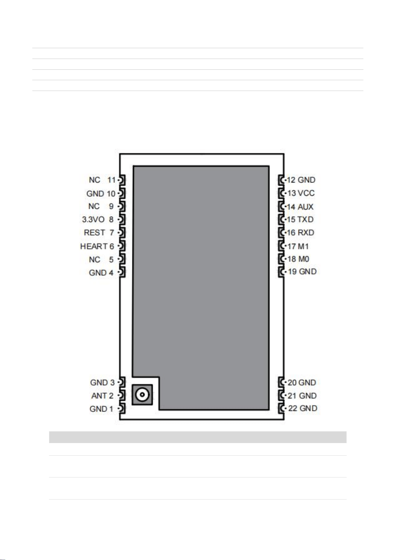
Pin definition
Pin name
Pin direction
Pin usage
GND
-
Power supply reference ground
M0
I
Mode 0 pin (internal 1MΩ weak pull-up), and the combination of M0 and M1
determines the working mode of the module.
M1
I
Mode 1 pin (internal 1MΩ weak pull-up), M0 and M1 together determine the
working mode of the module.

Silent Smart Technology Co., Ltd.
7 / 35
RXD
I
UART data input, connected to external TXD output pin
TXD
O
UART data output, connected to external RXD input pin
AUX
O
Module mode status pin
VCC
I
Power supply, the range of 3.0V~5.5V is greater than 3.5V to ensure full power
output.
3.3VO
-
Modular system 3.3V power supply, users don't need to pay attention, no network
connection, NC processing.
REST
I
Module reset pin, active at low level, with internal reset circuit, users do not need
external reset circuit, NC processing or connecting MCU controller pin.
HEART
O
Module heartbeat pin, which outputs a square wave with a period of 1s and a
logic level of 3.3V Users can NC process or connect LED or MCU input pin.
Note that this pin may affect sleep and receive current if it is connected to
equipment.
ANT
I/O
Radio frequency interface, stamp hole
NC
-
No connection required
3
hardware design
The supporting voltage range of the module is 3.0-5.5V, and the module performance can be satisfied when it is
greater than 3.5V, and the power supply for the module needs to meet the transient load capacity of ≥300mA;
It is suggested to add 22uF+0.1uF capacitor near the power input port outside the WS8475 module;
When the serial port is connected to an external device or MCU, it is suggested that TXD and RXD should reserve a
4.7k pull-up resistor to a 3.3V power supply without welding.
Reset the existing circuit inside the REST pin, which can be reset at low level. It is suggested to reserve an MCU pin
for control.
4 function declaration
4.1 Pattern description
The module mode is controlled by the module mode pins (M0, M1), and there are four modes in total: 0~3. M0 or M1 is 0, which
means pulling low; A value of M0 or M1 is 1, which means pulling high.
model
M1
M0
model
remarks
0
0
0
Transmission
mode
In this mode, RF works normally, and supports transparent transmission,
broadcasting, monitoring, fixed point and other functions.
Among them, transparent transmission and fixed-point functions are determined by
Silent Smart Technology Co., Ltd.
8 / 35
transmission mode parameters;
The receiver is in the same mode.
one
0
one
WOR
transmission
mode
The receiver is in WOR receiving mode or transmission mode; In this mode, the
transmission power consumption increases.
2
one
0
WOR receiving
mode
In this mode, the module periodically sleeps and wakes up to reduce power
consumption, and the sleep and wake-up period is determined by WOR parameters,
which is used in conjunction with WOR transmission.
three
one
one
Hibernation,
configuration
mode
The module enters the sleep mode, in which the module current is less than 2uA, and
parameter configuration is supported.
4.1.1 Transmission mode (mode 0)
The transmission mode, namely mode 0, is realized when M0 and M1 are pulled low at the same time.
In the transmission mode, the module can be configured as transparent transmission function, fixed-point transmission function
and broadcast transmission function.
(Note: In the following example, if the parameters are not specified, the wireless address, wireless channel, wireless airspeed,
encryption method and key parameters must be consistent.)
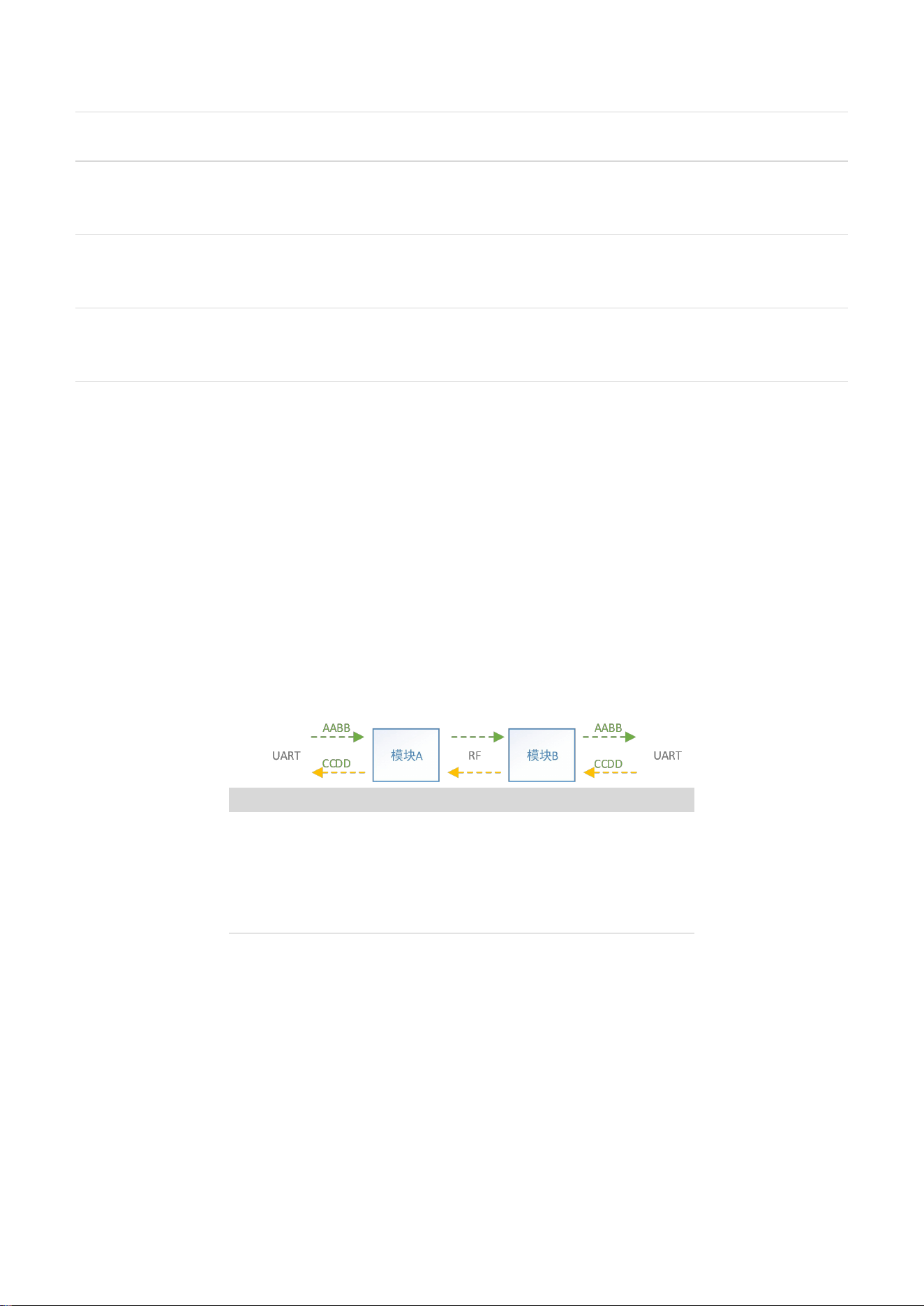
4.1.1.1 Transparent transmission function
Example of scenario:
Module a
Module b
Working mode: transparent
transmission mode
Address: 0x0000
Channel: 0x20
Network id: 0
Working mode: transparent
transmission mode
Address: 0x0000
Channel: 0x20
Network id: 0
Module A receives data through serial port: AA BB, and then sends it to module B through radio frequency; after receiving data,
module B outputs data through serial port: AABB; After receiving serial port data: CC DD, module B sends data to module A through
radio frequency, and module A outputs data CC DD through serial port after receiving data. It is up to the user to send and receive data
on both sides.
In transparent transmission mode, modules communicating with each other must have the same address and channel (except
address 0xFFFF, which is broadcast and monitoring address).
Note: In the transparent transmission function, the data received by serial port is directly transmitted by radio frequency, without
any format conversion and data packaging.
Silent Smart Technology Co., Ltd.
9 / 35
4.1.1.2 Broadcasting and monitoring functions
Broadcast function: When the module address of the sender is 0xFFFF(65535), the data sent by the sender can be received by the
module at any address (provided that the airspeed, channel and network ID of the sender and receiver are the same or 255).
Listening function: When the address of the receiver module is 0xFFFF(65535), the receiver can receive the data sent by the
sender module at any address (provided that the airspeed, channel and network ID of the transmitter and receiver are the same or 255).
4.1.1.3 Fixed point transmission function
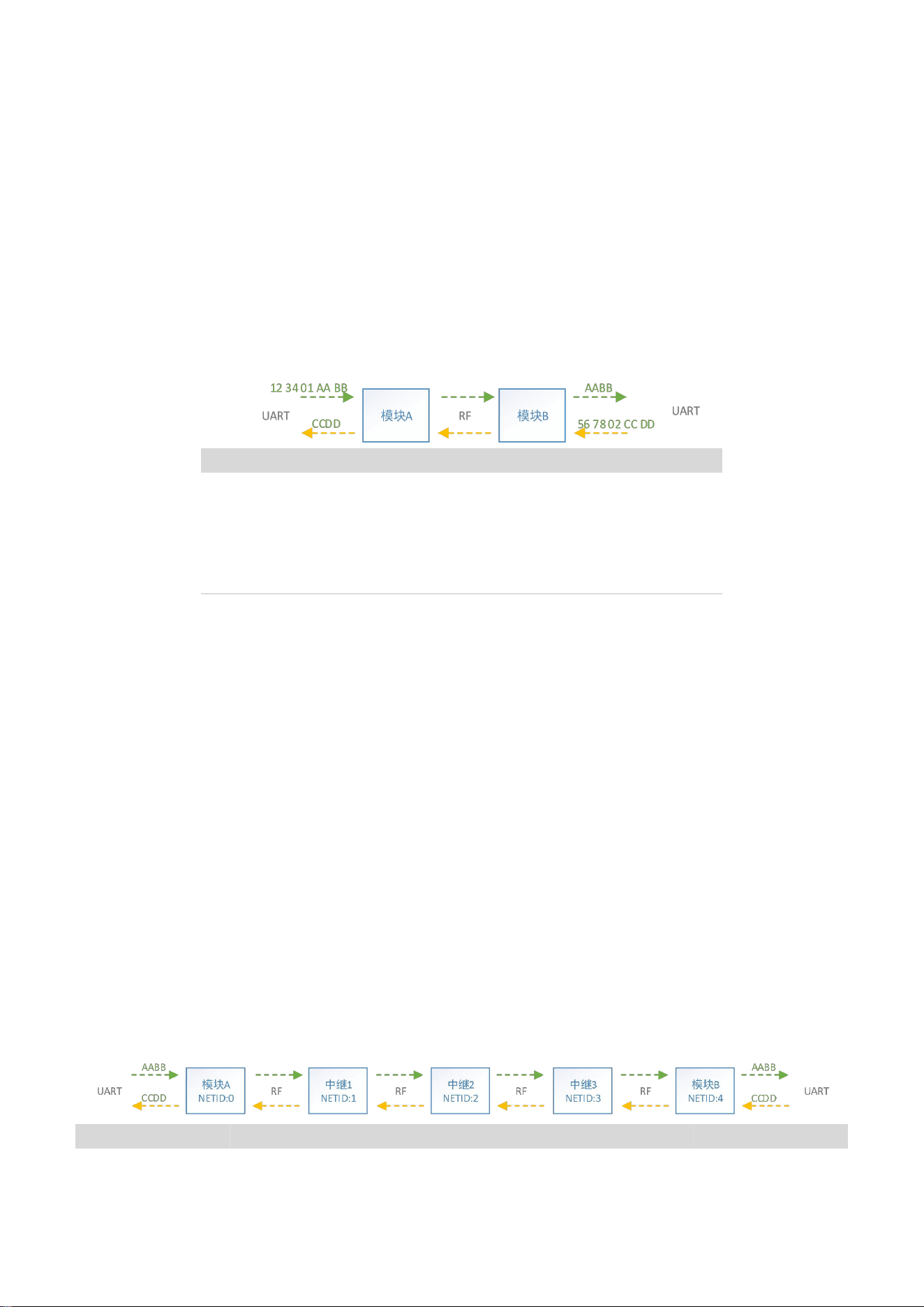
Example of scenario:
Module a
Module b
Working mode: fixed-point
mode
Address: 0x5678
Channel: 0x02
Network id: 0
Working mode: fixed-point mode
Address: 0x1234
Channel: 0x01
Network id: 0
Module A receives data through serial port: 123401aaabb, where 0x1234 is the address of the target module and 0x01 is the
channel of the target module. The data are all in hexadecimal, and the data is sent to module B through radio frequency. After receiving
the data, module B outputs the data through serial port: aabb; Module B receives data through serial port: 56 78 02 CC DD, where
0x5678 is the address of the target module and 0x01 is the channel of the target module. The data are all in hexadecimal, and the data
is sent to module A through radio frequency. After receiving the data, module A outputs the data through serial port: CC DD.
Transmission format: high byte of destination address+low byte of destination address+destination channel+transmission data.
Note: 1) The data is sent in hexadecimal. In the fixed-point transmission function, the module needs to add the address and
channel of the target module before sending the data.
2) In fixed-point mode, the transmission address and channel will also be included in the packet length calculation.
4.1.1.4 Relay transmission function
Example of scenario:
Module a
Relay 1
Relay 2
Relay 3
Module b

Silent Smart Technology Co., Ltd.
10 / 35
Relay Enable: No.
Address: 0x1234
Network id: 0x00
Relay Enable: Yes
Address: any
Network id: 0x01
Relay Enable: Yes
Address: any
Network id: 0x02
Relay Enable: Yes
Address: any
Network id: 0x03
Relay Enable: No.
Address: 0x1234
Network id: 0x04
With this parameter configuration, modules A and B can communicate with each other and forward through relays 1, 2 and 3.
Attention should be paid to the following parameter requirements when using this relay:
The network ID in the relay network must be set in sequence, and the sequence step is 1.
The relay in the relay network needs to be configured to be relay enabled.
The communication modules (modules A and B) in the relay network can be in transparent transmission mode.
All modules in the relay network need to be in the same channel and at the same airspeed.
Modules A and B can be composed of multiple modules with different addresses, but the addresses of modules that need to
communicate must be the same or meet the broadcasting conditions (address is 0xffff).
4.1.1.5 AT configuration function
In the transmission mode, you can use the AT command to configure, and send the ASCII character "++"to enter the AT
configuration. After entering the AT configuration, the module will respond "\r\n+OK\r\n", which means that the module has entered
the AT configuration. When you send a configuration command or a query command, you can receive the response of the
configuration query command. After the module enters AT configurATion, it will receive the correct configuration command within
20S, and the countdown will be refreshed for 20S. If the configuration command is not received after 20S, the module will exit the
configuration, and at the same time, the module serial port will output "\r\n+EXIT\r\n", which means that it has exited the
configuration and returned to the RF data transmission function before AT configuration.
Note: In the transmission mode, the configuration needs to wait for the RF to be idle before sending the AT configuration
command (the AUX status can be detected as high before sending the command to enter the AT configuration), otherwise the response
of the command to enter the AT configuration may be delayed.
4.1.2 WOR mode (modes 1 and 2)
WOR modes are modes 1 and 2. When M0 is pulled low and M1 is pulled high, it is mode 1, that is, WOR transmission mode;
When M0 is pulled high and M1 is pulled low, it is mode 2, that is, WOR receiving mode.
In WOR mode, the WOR parameters need to be set at the sender and the receiver. The longer the WOR period, the longer the
sending time of the sender, the higher the power consumption, the higher the delay of the receiver and the lower the power
consumption.
4.1.3 Configuration, Sleep Mode (Mode 3)
Configuration and sleep mode, namely mode 3, is realized when M0 and M1 are pulled high at the same time. When configuring,
the default baud rate is 9600bps, with no check and 1 stop bit. When the serial port receives the configuration command, it will wake
up the mcu to analyze the execution command and continue to sleep after the execution is completed.

Silent Smart Technology Co., Ltd.
11 / 35
4.1.3.1 sleep mode
In this mode, the module will enter low power consumption, and the average current of the module is lower than 2uA. When
sleeping, the corresponding functional pin levels of the module are shown in the following table:
serial
number
pin
Pin state at sleep
Output and input modes
one
M0
up level
Pull up input
2
M1
up level
Pull up input
three
AUX
up level
Pull up input
four
UART_RX
up level
Pull up input
five
UART_TX
up level
Push-pull output
4.1.3.2 Parameter configuration
4.1.3.2.1 Configuration, configuration in sleep mode
Parameter configuration function is supported in configuration and sleep modes. During parameter configuration, the fixed serial
communication parameter is baud rate of 9600bps, and there is no verification. For configuration commands, refer to the chapter of
Parameter Configuration. ConfigurATion uses hexadecimal to send configuration commands, and at instruction configuration is also
supported.
4.1.3.2.2 Configuration in transmission mode
Configuration is also supported in transmission mode (only AT command is supported, and the baud rate of configuration is
determined by the baud rate of configuration). You need to send "+++"to enter AT command configuration mode. For detailed
instructions, please refer to the chapter of AT Command Configuration.
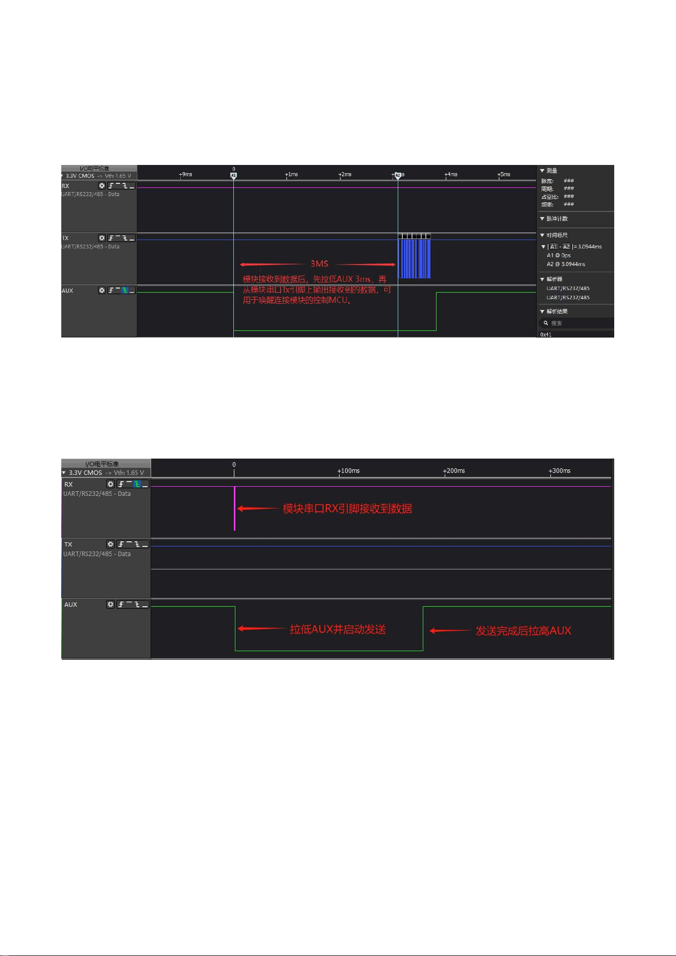
4.2 Module status indication
The module status is indicated by the AUX pin. When AUX is low, it represents the busy status of the module. The busy status of
the module has the following situations:
The serial port is sending and receiving data or the serial port buffer is not empty.
Radio frequency is sending data.
Module is initializing or software resetting.
The module is entering other modes from sleep mode.
Therefore, when operating the module, it is best to judge the AUX state first, and then operate the module when the AUX
pin level is high.
Silent Smart Technology Co., Ltd.
12 / 35
4.2.1
Receiving data AUX status indication
After receiving the data, the module pulls down the AUX pin for 3ms, and then outputs the data from the TXD pin of the serial
port. This function can be used to wake up the user MCU and receive data.
4.2.2
Send data AUX status indication
When sending data, the module receives the data through the serial port, and then pulls AUX down until the data reception is
completed or the maximum subcontracting length is reached, and then starts RF transmission, and then pulls AUX up after RF
transmission is completed.
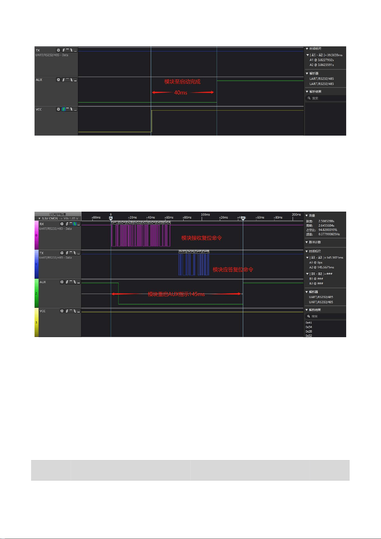
4.2.3
Power-on AUX status indication
The power-on timing of the module is shown in the figure. When the module is fully powered on, VCC becomes high, and the
module starts to initialize, while AUX remains low until the module initialization is completed. The time from the stable power supply
to the completion of module initialization is about 40 ms.
Silent Smart Technology Co., Ltd.
13 / 35
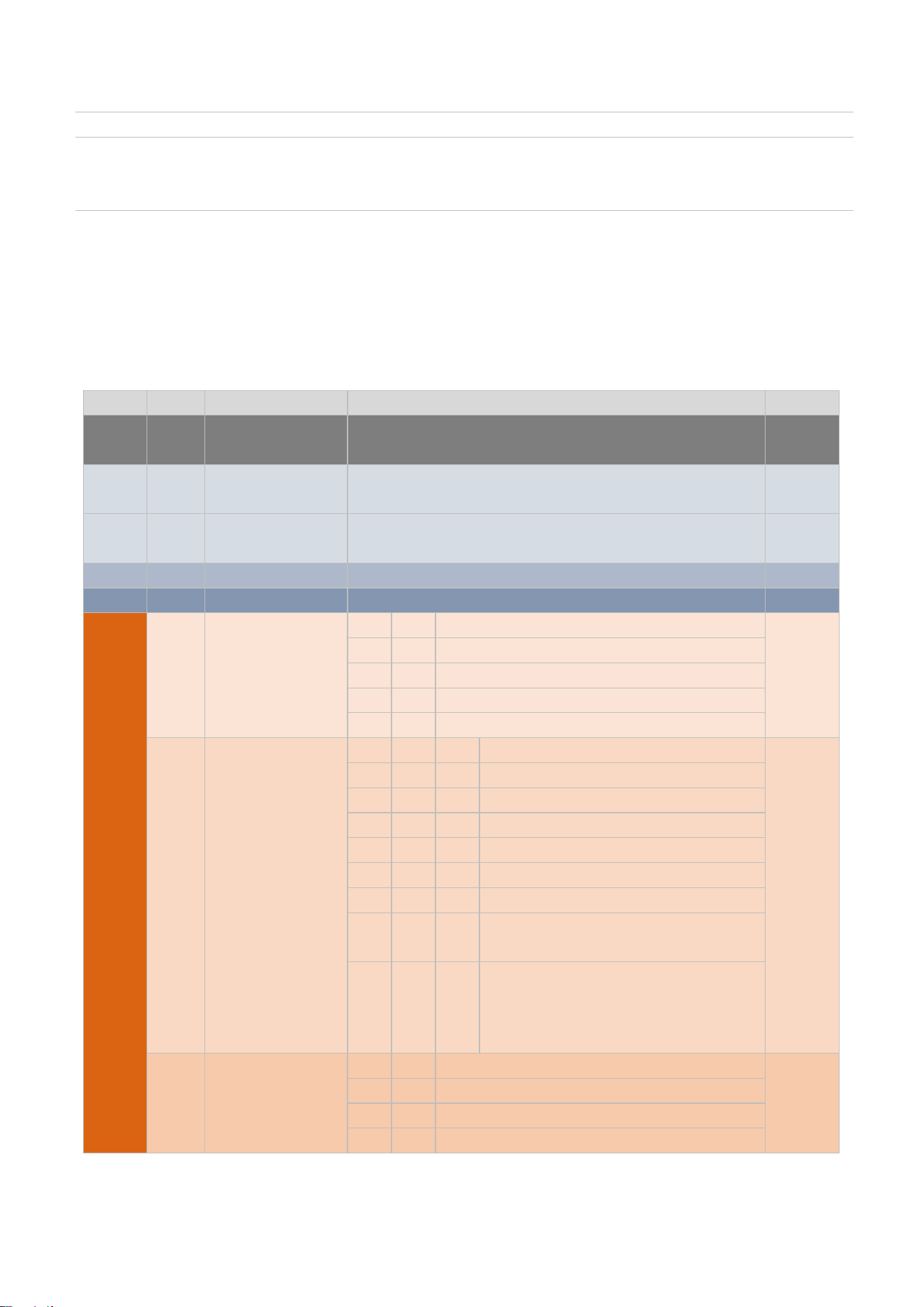
4.2.4 AT command resets AUX status indication.
After receiving the AT+RST reset command, the module pulls AUX low and responds to the reset command. After the response
is completed, restart will be started until the restart initialization is completed in about 145 ms (at 1200 bps baud rate, it is about 40ms
at 145ms(1200bps baud rate).
4.3 Restore factory settings
Restoring the factory settings of the module means that all parameters are restored to the factory default parameters. Restoring the
factory parameters is realized by command. In configuration and sleep mode, data 0xC5 0xC5 0xC5 is sent to the module, and the
module starts to reset the parameters and restart after receiving it. You can also use AT command AT+RESTRORE to restore factory
settings in transmission mode.
4.4 Factory default parameters
Factory default parameters: 00 00 00 00 30 40 00 14 BF 07 D0A0A1 A2 A3A4A5AA7 A9 AA AB AC AD AE AF.
Baud rate
Check Digit
airspeed
Default
channel
address
LBT
RSSI
Transmit
power

Silent Smart Technology Co., Ltd.
14 / 35
115200bps
No parity
2.4kbps
twenty
0
disability
disability
12.3dBm
5 Parameter configuration
Configuration needs to be in mode 3 (configuration and sleep mode), with baud rate fixed at 9600bps and 8 data bits, without
verification, and the configuration command is sent in hexadecimal.
5.1 Register configuration
5.1.1
Brief introduction of configuration instruction
The supported instruction formats are as follows (all commands are sent in hexadecimal, and must be sent continuously, and
frames cannot be broken):
serial
number
instruction
format
explain
remarks
one
C0+ operating
parameters
Configuration parameter command (power-off saving) C0+27 bytes working
parameters
For example:
Send the command c000000000 30 40000 14bf07d0a1a2a3a4a5a6a7 A8 A9 AA
AB AC AD AE AF.
Module response c000000000 30 40000 14bf07d0a1a2a3a4a5a6a7 A8 A9 AA AB
AC AD AE AF
2
C1 C1 C1
Read module parameter command
For example:
Send command C1 C1 C1
Module response C1 00 00 00 30 40 00 14bf07d0
The key is
unreadable.
three
C2+ operating
parameters
Configure temporary parameter command (power off without saving) C2+27 bytes
working parameters.
For example:
Send command C2 00 00 00 00 30 40 00 14 BF 07 d0A0A1 A2 A3A4A5AA7 A8
A9 AA AB AC AD AE AF.
Module response C2 00 00 00 00 30 40 00 14 BF 07 d0A0A1 A2 A3A4A5AA7 A8
A9 AA AB AC AD AE AF
four
C3 C3 C3
Read module model and version command
For example:
Send command C3 C3 C3
Module response C3 57 53 38 34 37 35 44 48 53 20 56 33 2e30 2e32 (ASCII)
Corresponding string: ws 8475 v3.0.2.
five
C4 C4 C4
Reset module command
For example:
Silent Smart Technology Co., Ltd.
15 / 35
Send command C4 C4 C4 module response C4 C4 C4.
six
C5 C5 C5
Recovery module parameters are factory-set parameters.
For example:
Send command C5 C5 C5 module response C5 C5 C5.
5.1.2
Configuration register description
There are 27 configuration registers in total, corresponding to 27 bytes (1 byte per register); The configuration command is 1 byte and
the configuration parameters are 28 bytes in total.
register
Bit bit
Parameter name
explain
remarks
0
7~0
Command 0xC0 or
0xC2
The configuration command is fixed to 0xC0 (power failure to save) or
0xC2 (power failure not to save).
one
7~0
High 8 bits of module
address
The module address parameter has 8 high bits, and the default value is
0x00.
2
7~0
Low 8 bits of module
address
The module address parameter has 8 lower bits, and the default value is
0x00.
three
7~0
reserve
The default value is 0x00, just write 0 when configuring.
four
7~0
Network ID
0~255, the default is 0, and the sender and receiver must be the same.
five
7~6
Serial parity bit
bit7
bit6
Corresponding parity bit value
0
0
No check (8N1, default)
0
one
Odd check (8O1)
one
0
Even check (8E1)
one
one
No check (8N1)
5~3
Serial baud rate
bit5
bit4
bit3
Corresponding baud rate value
The
configurat
ion baud
rate is
fixed at
9600bps,
and the
communi
cation
baud rate
can be
configure
d.
0
0
0
Baud rate 1200bps
0
0
one
Baud rate 4800bps
0
one
0
Baud rate 9600bps (configured baud rate)
0
one
one
Baud rate 19200bps
one
0
0
Baud rate 38400bps
one
0
one
Baud rate 57600bps
one
one
0
Baud rate 115200bps (default communication
baud rate)
one
one
one
Baud rate 256000bps
2~1
Serial stop bit
bit2
bit1
Bit value corresponding to stop bit
0
0
1 bit (default)
0
one
1.5 bit
one
0
2 bits

Silent Smart Technology Co., Ltd.
16 / 35
one
one
1 bit
0
reserve
six
7~5
Wireless air rate
bit7
bit6
bit5
Corresponding wireless air rate
0
0
0
The air speed is 2.4kbps.
0
0
one
The air speed is 2.4kbps.
0
one
0
The air rate is 2.4kbps (default).
0
one
one
The air speed is 4.8kbps.
one
0
0
The air speed is 9.6kbps.
one
0
one
The air speed is 19.2kbps.
one
one
0
The air speed is 38.4kbps.
one
one
one
The air speed is 62.5kbps.
4~3
Wireless transmission
power
bit4
bit3
Corresponding power value
0
0
0
one
12.3 dBm
one
0
11 dBm
one
one
10dBm
2
Packet RSSI
Output enable
bit2
Packet RSSI output enable bit
Complem
ent output
Follow
the
received
data
output
0
Turn off the packet RSSI function (default)
one
Turn on the packet RSSI function.
one
Real-time channel
RSSI read enable
bit1
Real-time channel RSSI read enable bit
After
opening,
it can be
read by
AT
command
.
0
Turn off the real-time channel RSSI reading function (default)
one
Turn on the real-time channel RSSI reading function (it can be
read in transparent transmission mode after being enabled).
0
reserve
seven
7~5
WOR
Wireless wake-up
time
bit7
bit6
bit5
WOR wireless wake-up time value
0
0
0
250ms (default)
0
0
one
500ms
0
one
0
750ms
0
one
one
1000ms
one
0
0
1250ms
one
0
one
1500ms
one
one
0
1750ms
one
one
one
2000ms
four
LBT enable
bit4
LBT function enable bit
When the
detected
0
Turn off LBT (default)

Silent Smart Technology Co., Ltd.
17 / 35
environm
ental
noise is
lower
than the
threshold,
the
transmissi
on is
started.
one
Turn on lbt (after lbt is enabled, the module will start sending
according to the current environmental noise, and the
environmental noise will continue to be higher than the
threshold for 2s, and the module will send after 2s timeout).
three
Preamble detection
enabled (WOR
receive mode)
bit3
Preamble enable bit in WOR receiving mode
Aux pin
pulled
low for
5ms was
detected.
0
Turn off the preamble detection function in WOR receiving
mode.
one
Turn on the preamble detection function in WOR receiving
mode.
2
Relay enable
bit2
Relay is potential.
0
Turn off trunking (default)
one
Turn on the relay
one
Echo of AT
instruction
bit1
Echo of AT instruction is energy bit.
0
Turn off echo (default)
one
Turn on echo
0
Fixed-point mode
enable
bit7
Fixed-point mode enable bit
0
Turn off fixed-point mode and transparent transmission mode
(default)
one
Turn on fixed-point mode
eight
7~0
Module channel
0~80, a total of 81, the default channel 20 (corresponding to the
frequency of 869.75M),
Operating frequency: 849.75+ channel value (MHz)
nine
7~0
LBT threshold value
Default 0xBF(-65), complement value
10-11
16~0
LBT timeout
The default value is 0x07D0(2000), in ms bits.
12-27
-
encryption key
Default: A0A1 A2 A3A4A5AA7 A8 A9 AA AB AC AD AE AF
16 bytes
Because the generated parameters are composed of bits, it is suggested to use the generated parameters of upper computer
WSXT_Setting for verification.
5.2 AT instruction configuration
The transmission mode is entered by sending the character "++",which is three characters in total, without carriage return and
line feed, which is different from other instructions; At the same time, after entering with this command, the module response is also
different from the configuration instruction, and the module will respond "\r\n+OK\r\n". If you don't receive a valid AT command
within 20s, you will automatically exit the AT configuration mode and output "\ r \ n+exit \ r \ n"; If a valid AT command is received
within 20s, the countdown to exit AT configuration mode will be refreshed. The configured baud rate in transmission mode is

Silent Smart Technology Co., Ltd.
18 / 35
consistent with the baud rate of transmission data (determined by the configured serial port parameters).
Configuration mode can be configured without sending "++".In configuration mode, baud rate bits 9600bps and 8N1 are fixed.
Symbol description
symbol
explain
<CR>
Enter, hexadecimal 0x0D
<LF>
Line feed, hexadecimal 0x0A
5.2.1
AT instruction list
instruction
describe
Effective mode
remarks
AT
test instruction
--
ATE
Set/query command echo switch
be effective
immediately
AT+RST
system reset
be effective
immediately
AT+RESTORE
Restore factory settings
be effective
immediately
The software resets
and exits
configuration.
AT+GMR
Query module information
--
AT+UART
Set/query serial port parameters
Restart takes effect
Or withdraw from
the allocation to
take effect
AT+CHAN
Set/query wireless channel range
Restart takes effect
AT+RATE
Set/query wireless airspeed
Restart takes effect
AT+PWR
Set/query wireless transmission power
Restart takes effect
AT+PKTRSSI
Set/query packet RSSI enable
be effective
immediately
AT+RSSI
Set/Query Real-time RSSI Enable
be effective
immediately

Silent Smart Technology Co., Ltd.
19 / 35
AT+WOR
Set/query WOR wake-up period
be effective
immediately
AT+LBT
Set/query LBT function
be effective
immediately
AT+LPWRPREAM
Set/query the enabling of preamble detection in WOR
receiving mode.
be effective
immediately
AT+RELAY
Set/query relay function enabled.
be effective
immediately
AT+TRANSMOD
Set/query transmission mode control (transparent
transmission and fixed-point transmission)
be effective
immediately
AT+KEY
Set the communication transmission key (write only)
be effective
immediately
AT+NETID
Set/query network ID
be effective
immediately
AT+ADDR
Set/query module address
be effective
immediately
AT+SCAN
Scan the current RSSI of the query module channel.
--
AT+EXIT
Exit configuration module
be effective
immediately
5.2.2 Detailed explanATion of at instruction
5.2.2.1 Test instruction AT
Instruction
description
Test instruction, used for handshake test.
execution
instruction
AT<CR><LF>
respond
<CR><LF>OK<CR><LF>

Silent Smart Technology Co., Ltd.
20 / 35
description
of
parameter
without
5.2.2.2 Echo control instruction ATE
Instruction
description
Used to turn command echo on or off.
execution
instruction
ATE[<value>]<CR><LF>
respond
<CR><LF>OK<CR><LF>
description
of
parameter
<value>
0: Turn off echo
1. Open echo
example
ATE1<CR><LF > open echo
5.2.2.3 Reset instruction AT+RST
Instruction
description
This command restarts the device. If the AT configuration is sent in transparent mode, the configuration mode will be
exited.
execution
instruction
AT+RST<CR><LF>
respond
<CR><LF>OK<CR><LF>
description
of
parameter
without

Silent Smart Technology Co., Ltd.
21 / 35
5.2.2.4 Restore factory setting instruction AT+RESTORE
Instruction
description
This command will reset the device once, and if the command is sent by AT configuration in transparent mode, it will
exit the configuration mode.
execution
instruction
AT+RESTORE<CR><LF>
respond
<CR><LF>OK<CR><LF>
description
of
parameter
without
5.2.2.5 View version information instruction AT+GMR
Instruction
description
Used to query the equipment model and version number.
execution
instruction
AT+GMR? <CR><LF>
respond
<CR><LF>+GMR: <module name>,<version><CR><LF>
<CR><LF>OK<CR><LF>
description
of
parameter
< module name >: product model.
< version >: product version
5.2.2.6 Serial port operation instruction AT+UART
Instruction
description
Used to query and set serial port parameters.
execution
instruction
query
AT+UART? <CR><LF>
deploy
AT+UART=<baud>,<parity>,<stop><CR><LF>

Silent Smart Technology Co., Ltd.
22 / 35
respond
<CR><LF>+UART=<baud>,<parity>,<stop>
<CR><LF><CR><LF>OK<CR><LF>
<CR><LF>OK<CR><LF>
description
of
parameter
< baud >: baud rate of serial port.
0:1200bps
1:4800bps
2:9600bps
3:19200bps
4:38400bps
5:57600bps
6: 115200 bps (default)
7:256000bps
< parity >: parity bit
0: No verification.
1. Odd check
2: Even check
3: No verification
< stop >: stop bit
0: 1 bit
1: 1.5 bit
2: 2 bit
3: 1 bit
Note: The data bit width is 8 bits when there is no check, and 9 bits when there is check.
example
AT+UART=6,0,0<CR><LF>
5.2.2.7 Channel operation instruction AT+CHAN
Instruction
description
Used to query and set the working channel.
execution
query
deploy

Silent Smart Technology Co., Ltd.
23 / 35
instruction
AT+CHAN? <CR><LF>
AT+CHAN=<ch><CR><LF>
respond
<CR><LF>+CHAN=<ch><CR><LF>
<CR><LF>OK<CR><LF>
<CR><LF>OK<CR><LF>
description
of
parameter
< ch >: wireless channel
0~80 (default value is 20)
Note: the channel interval is 1M, the initial channel is 849.75M, and the default channel 20 corresponds to the
frequency point of 849.75+1 * 20 = 869.75M
example
AT+CHAN=20<CR><LF>
5.2.2.8 Wireless airspeed operation command AT+RATE
Instruction
description
Used to query and set the wireless airspeed.
execution
instruction
query
AT+RATE? <CR><LF>
deploy
AT+RATE=<level><CR><LF>
respond
<CR><LF>+RATE =<level><CR><LF>
<CR><LF>OK<CR><LF>
<CR><LF>OK<CR><LF>
description
of
parameter
< level >: airspeed (baud rate in the air)
0: airspeed 2.4kbps
1: airspeed 2.4kbps
2: airspeed 2.4kbps (default)
3: airspeed 4.8kbps
4: airspeed 9.6kbps
5: the airspeed is 19.2kbps
6: airspeed 38.4kbps
7: airspeed 62.5kbps
Note: The higher the airspeed, the smaller the transmission delay and the shorter the transmission distance.
example
AT+RATE=2<CR><LF>

Silent Smart Technology Co., Ltd.
24 / 35
5.2.2.9 Wireless transmit power operation instruction AT+PWR
Instruction
description
Set and query the wireless transmission power, with a total of four levels.
execution
instruction
query
AT+PWR? <CR><LF>
deploy
AT+PWR=<pwr><CR><LF>
respond
<CR><LF>+PWR=<pwr><CR><LF>
<CR><LF>OK<CR><LF>
<CR><LF>OK<CR><LF>
description
of
parameter
< pwr >: wireless transmission power
example
AT+PWR=0<CR><LF>
5.2.2.10 Packet RSSI operation instruction AT+PKTRSSI
Instruction
description
It is used to query and set the RSSI enable of data packets, and receive data frames with radio frequency for output.
execution
instruction
query
AT+PKTRSSI? <CR><LF>
deploy
AT+PKTRSSI=<en><CR><LF>
respond
<CR><LF>+PKTRSSI=<en><CR><LF>
<CR><LF>OK<CR><LF>
<CR><LF>OK<CR><LF>
description
of
parameter
< en >: packet RSSI enabled.
0, turn off packet RSSI (default)
1. Turn on RSSI of data packet.
Note: After the RSSI of the data packet is turned on, every time the module receives a packet of RF data, it will add a
byte of the signal strength of the received data packet at the end of the data and output it in the form of complement.
example
AT+PKTRSSI=1<CR><LF>

Silent Smart Technology Co., Ltd.
25 / 35
5.2.2.11 Real-time RSSI operation instruction AT+RSSI
(1) Setting environmental noise enabling and disabling in configuration mode
Instruction
description
Used to query and set the reading enable of real-time RSSI value of the current channel.
execution
instruction
query
AT+RSSI? <CR><LF>
deploy
AT+RSSI=<en><CR><LF>
respond
<CR><LF>+RSSI=<en><CR><LF>
<CR><LF>OK<CR><LF>
<CR><LF>OK<CR><LF>
description
of
parameter
< en >: real-time RSSI enabled.
0, turn off real-time RSSI (default)
1. Turn on real-time RSSI.
Description: After the real-time RSSI is turned on, AT+RSSI command is supported to read the real-time RSSI value of
the current channel in transmission mode.
example
AT+RSSI=1<CR><LF>
(2) reading the real-time RSSI value in transmission mode
Instruction
description
Used to query the current real-time RSSI value (in transmission mode)
execution
instruction
query
AT+RSSI? <CR><LF>
respond
<CR><LF>+RSSI=<val><CR><LF><CR><LF>OK<CR><LF>
description
of
parameter
< val >: real-time RSSI value.
0~-128dBm: the real-time RSSI value of the current channel.
Note: Real-time RSSI can only be read in transmission mode after it is turned on.
example
AT+RSSI=-60<CR><LF>
5.2.2.12 WOR cycle configuration instruction AT+WOR
Instruction
description
Setting and querying wireless communication address

Silent Smart Technology Co., Ltd.
26 / 35
execution
instruction
query
AT+WOR? <CR><LF>
deploy
AT+WOR=<val><CR><LF>
respond
<CR><LF>+WOR=<val><CR><LF>
<CR><LF>OK<CR><LF>
<CR><LF>OK<CR><LF>
description
of
parameter
< val >: WOR cycle setting
0: 250 ms (default)
1:500ms
2:750ms
3:1000ms
4:1250ms
5:1500ms
6:1750ms
7:2000ms
example
AT+WOR=1<CR><LF>
5.2.2.13 LBT operation instruction AT+LBT
Instruction
description
Used to query and set LBT parameters.
execution
instruction
query
AT+LBT? <CR><LF>
deploy
AT+LBT=<en>,<thresh>,<timout><CR><LF>
respond
<CR><LF>+LBT=<en>,<thresh>,<timout>
<CR><LF><CR><LF>OK<CR><LF>
<CR><LF>OK<CR><LF>
description
of
parameter
< en >:LBT enabled
0: turn off LBT (default)
1: turn on LBT
< threshold >: threshold value of lbt detection signal strength (RSSI)
0 ~-128: RSSI threshold (default -65)

Silent Smart Technology Co., Ltd.
27 / 35
< timeout >: timeout.
0~5000: timeout value in milliseconds (default is 2000).
Description:
1. The last two parameters can be ignored when the RSSI value is turned off.
2. The RSSI threshold is related to the antenna. The higher the antenna gain, the higher the threshold should be set.
example
AT+LBT=1,-70,2000<CR><LF>
5.2.2.14 Preamble detection enable operation instruction AT+LPWRPREAM
Instruction
description
Used to query and set the enabling of preamble detection indication (indicated by AUX).
execution
instruction
query
AT+LPWRPREAM? <CR><LF>
deploy
AT+LPWRPREAM=<en><CR><LF>
respond
<CR><LF>+LPWRPREAM=<en><CR><LF>
<CR><LF>OK<CR><LF>
<CR><LF>OK<CR><LF>
description
of
parameter
< en >: preamble detection is enabled (effective in WOR receiving mode).
0, enabling preamble detection is turned off (default)
1. Enable preamble detection.
Note: After enabling preamble detection, in WOR receiving mode, if the preamble is detected, the AUX pin will be
pulled low for 5 ms..
example
AT+LPWRPREAM=1<CR><LF>
5.2.2.15 Relay enable operation instruction AT+RELAY
Instruction
description
Used to query and set the relay function enabling.
execution
instruction
query
AT+RELAY? <CR><LF>
deploy
AT+RELAY=<en><CR><LF>
respond
<CR><LF>+RELAY=<en><CR><LF>
<CR><LF>OK<CR><LF>
<CR><LF>OK<CR><LF>

Silent Smart Technology Co., Ltd.
28 / 35
description
of
parameter
< en >: relay enabled
0, turn off relay enabling (default)
1. Turn on relay enabling.
Note: After the relay is enabled, this module is only used for forwarding radio frequency data.
example
AT+RELAY=1<CR><LF>
5.2.2.16 Transmission mode operation instruction AT+TRANSMOD
Instruction
description
Used to query and set the relay function enabling.
execution
instruction
query
AT+TRANSMOD? <CR><LF>
deploy
AT+TRANSMOD=<val><CR><LF>
respond
<CR><LF>+TRANSMOD=<val><CR><LF>
<CR><LF>OK<CR><LF>
<CR><LF>OK<CR><LF>
description
of
parameter
< val >: transmission mode
0, transparent transmission mode (default)
1, fixed-point mode
Description: See the chapter on fixed-point mode for details.
example
AT+TRANSMOD=1<CR><LF>
5.2.2.17 Wireless key operation instruction AT+KEY
Instruction
description
Used to set the wireless key
execution
instruction
deploy
AT+KEY=<key_str><CR><LF>
respond
<CR><LF>OK<CR><LF>
description
of
parameter
< key_str >: hexadecimal string of the set key.
Hexadecimal string key of 16 bytes (default: A0A1A2A 3A 4A 5A 6A 7A 8A9 AAAbacadaeaf)
Description: A 16-byte hexadecimal string with 32 characters in total. No spaces are allowed in the string.

Silent Smart Technology Co., Ltd.
29 / 35
example
AT+KEY=A0A1A2A3A4A5A6A7A8A9AAABACADAEAF<CR><LF>
5.2.2.18 Network ID configuration instruction AT+NETID
Instruction
description
Setting and querying wireless network ID
execution
instruction
query
AT+NETID? <CR><LF>
deploy
AT+NETID=<id><CR><LF>
respond
<CR><LF>+ADDR=<id><CR><LF>
<CR><LF>OK<CR><LF>
<CR><LF>OK<CR><LF>
description
of
parameter
< ID >: network id value.
0 ~ 255: 0 (default)
Description:
1. Network ID must be the same to send and receive data normally (except ID=255).
2. When set to 255, data with any network ID can be received, and the sent data can also be received by modules
with any network ID.
example
AT+NETID=0<CR><LF>
5.2.2.19 Wireless communication address configuration instruction AT+ADDR
Instruction
description
Setting and querying wireless communication address
execution
instruction
query
AT+ADDR? <CR><LF>
deploy
AT+LOG=<val><CR><LF>
respond
<CR><LF>+ADDR=<val><CR><LF>
<CR><LF>OK<CR><LF>
<CR><LF>OK<CR><LF>
description
of
< val >: module address setting
0 ~ 65535: 0 (default)

Silent Smart Technology Co., Ltd.
30 / 35
parameter
Description:
1. The addresses of the sender and receiver must be the same, except for address 0x65535.
2. When the address is 65535, the module can receive data of any address, and can also receive data sent by the module
of any address.
example
AT+ADDR=1<CR><LF>
5.2.2.20 Channel current RSSI scanning configuration instruction AT+SCAN
Instruction
description
Inquire about RSSI instructions of current multiple channels
execution
instruction
query
AT+SCAN=<ch1>,<chn><CR><LF>
respond
<CR><LF>+SCAN=<ch1,val1>,<ch2,val2>,……. <chn,valn>,<CR><LF>
<CR><LF>OK<CR><LF>
description
of
parameter
< ch1 >: initial channel
0~96
< chn >: end channel
0~96
< val 1 >: RSSI value.
0~-128
Description:
1. The ending channel value cannot be greater than the starting channel value.
example
AT+SCAN=5,10<CR><LF> \r\n+SCAN:5,-78,6,-78,7,-78,8,-78,9,-78,10,-77\r\n\r\nOK\r\n
5.2.2.21 Exit configuration mode instruction AT+EXIT
Instruction
description
This instruction is used to manually exit configuration mode (configuration is valid only in transmission mode).
execution
AT+EXIT<CR><LF>

Silent Smart Technology Co., Ltd.
31 / 35
instruction
respond
<CR><LF>OK<CR><LF>
example
AT+EXIT<CR><LF>
6
Electrical and other parameters
6.1 Limit parameter
parameter
symbol
minimum value
maximum
unit
Power supply
voltage
VCC
-0.3
5.5
V
Interface voltage
VIN
-0.3
3.6
V
Radio frequency
input power
RFIN
-
+10
dBm
Storage
temperature
TSTG
-40
125
℃
6.2 working parameter
parameter
symbol
minimum
value
typical value
maximum
unit
Power supply
voltage
VCC
3.0
five
5.5
V
Communication
level
VIN
-0.3
3.3
3.6
V
Working
temperature
TOP
-40
-
eighty-five
℃
6.3 Radio frequency performance parameters
parameter
minimum
value
typical
value
maximum
unit
remarks
Working
frequency band
849.75
-
929.75
MHz
Air velocity
2.4
2.4
62.5
kbps

Silent Smart Technology Co., Ltd.
32 / 35
Transmit power
11 11.5 12.3
dBm
receiving
sensitivity
-
-124
-
dBm
2.4kbps@GFSK
emission
current
100
110
120
mA
Receiving
current
8.5
nine
9.5
mA
Dormant
current
1.5
2
2.5
uA
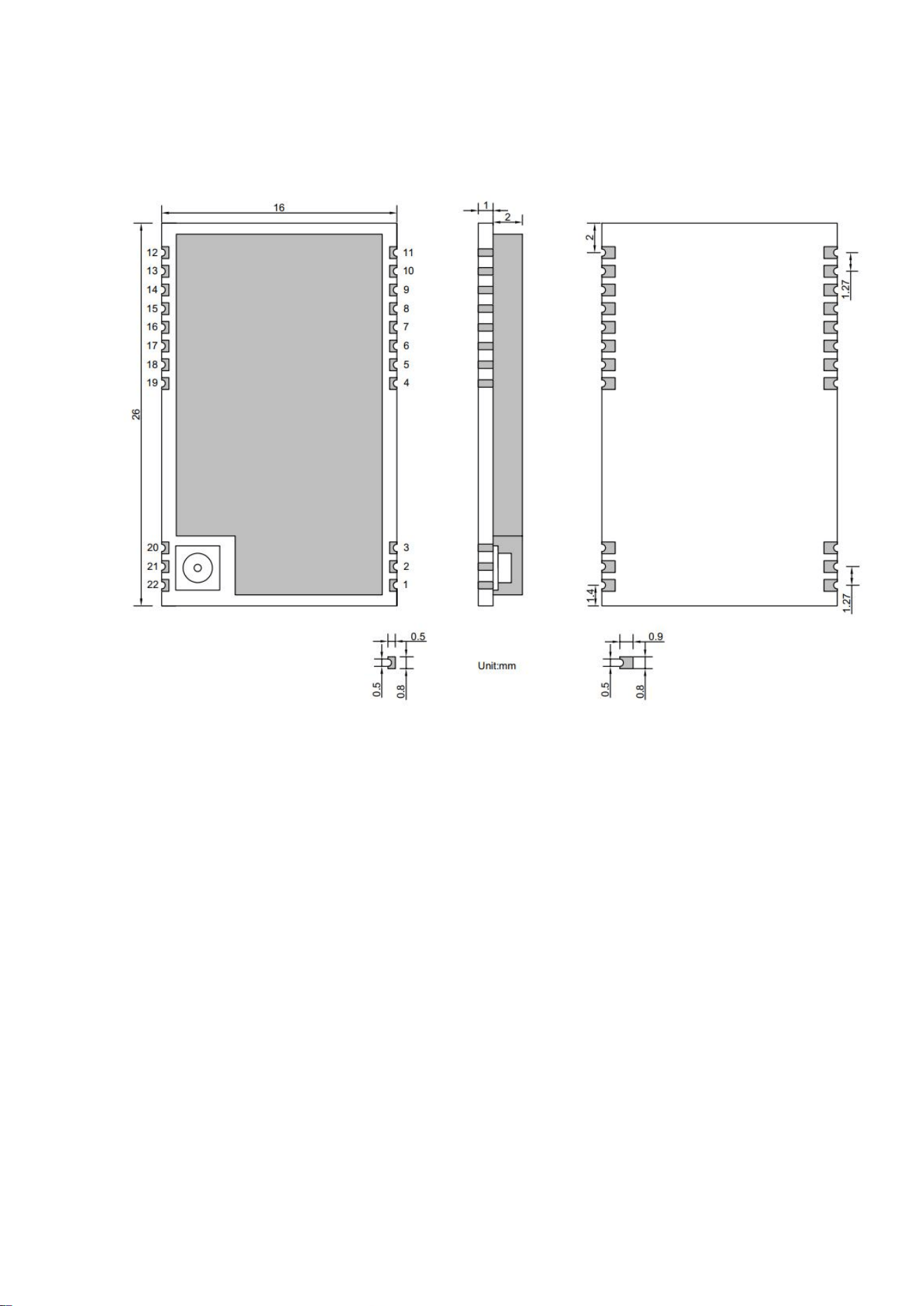
6.4 Package size
parameter
describe
communication
interface
UART
Radio
frequency interface
U.LF connector/stamp hole
package
Patch type
Interface mode
Stamp holes with 1.27mm spacing
outline
dimension
16*26*3mm (including shield)
weight
-
Silent Smart Technology Co., Ltd.
33 / 35
7 Package size
Silent Smart Technology Co., Ltd.
34 / 35
8 Production guidance
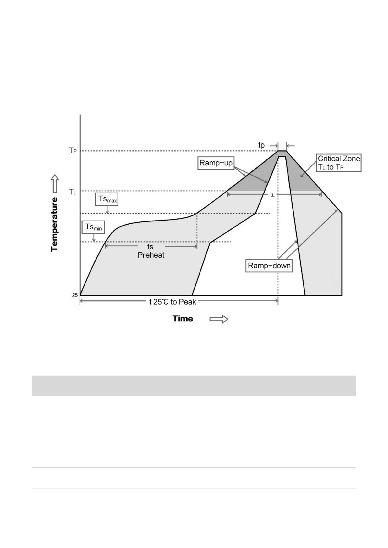
8.1 Reflow welding curve
8.2 Reflow soldering temperature and time
Curve
characteristics
Profile Feature
Sn-Pb Assembly
Pb-Free Assembly
tin cream
Solder Paste
Sn63/Pb37
Sn96.5/Ag3/Cu0.5
Minimum
preheating
temperature
Preheat Temperature min (Tsmin)
100℃
150℃
Maximum
preheating
temperature
Preheat temperature max (Tsmax)
150℃
200℃
preheating time
Preheat Time (Tsmin to Tsmax)(ts)
60-120 sec
60-120 sec
Average rising
Average ramp-up rate(Tsmax to
3℃/second max
3℃/second max

Silent Smart Technology Co., Ltd.
35 / 35
rate
Tp)
Liquid
temperature
Liquidous Temperature (TL)
183℃
217℃
Time above
liquidus
Time(tL)Maintained Above(TL)
60-90 sec
30-90 sec
Peak
temperature
Peak temperature(Tp)
220-235℃
230-250℃
Average decline
rate
Aveage ramp-down rate(Tp to
Tsmax)
6℃/second max
6℃/second max
Time from 25℃
to peak temperature
Time 25℃ to peak temperature
6 minutes max
8 minutes max
9 Contact information
contacts
mobile phone
mailbox
Manager Chen
15000319232
Tel: 028-64823553
Address: Room 303-7, Floor 3, Unit 4, Building 12, No.38 Jinke South Road, Jinniu High-tech Industrial Park, Chengdu

KDB 996369 D03 statements
2.2 List of applicable FCC rules:
The module complies with FCC Part 15.247.
FCC ID: 2BB8U-WS8475 on User manual and on the external of the packaging.
2.3 Summarize the specific operational use conditions
The module has been certified for Potable applications. This transmitter must not beco-located or
operating in conjunction with any other antenna or transmitter
2.4 Limited module procedures
The module is not a limited module.
2.5 Trace antenna designs
Not applicable
2.6 RF exposure considerations
This equipment complies with FCC’s RF radiation exposure limits set forth for an
uncontrolled environment. The antenna(s) used for this transmitter must not be collocated or operating
in conjunction with any other antenna or transmitter.
2.7 Antennas
The EUT use a permanently attached antenna which is unique.
2.8 Label and compliance information
The host system using this module, should have label in a visible area indicated the
following texts: “Contains FCC ID: 2BB8U-WS8475
2.9 Information on test modes and additional testing requirements
When testing host product, the host manufacture should follow FCC KDB Publication 996369 D04
Module Integration Guide for testing the host products. The host manufacturer may operate their
product during the measurements. In setting up the configurations, if the pairing and call box options
for testing does not work, then the host product manufacturer should coordinate with the module
manufacturer for access to test mode software.
The module has been certified for Potable applications. This transmitter must not be co-located or
operating in conjunction with any other antenna or transmitter
2.10 Additional testing, Part 15 Subpart B disclaimer
The module without unintentional-radiator digital circuity, so the module does not
require an evaluation by FCC Part 15 Subpart B. The host shoule be evaluated by the FCC Subpart B.
2.11 Note EMI Considerations
host manufacture is recommended to use D04 Module Integration Guide recommending as
"best practice" RF design engineering testing and evaluation in case non-linear interactions generate
additional non-compliant limits due to module placement to host components or properties
2.12 How to make changes
This module is stand-alone modular. If the end product will involve the Multiple simultaneously
transmitting condition or different operational conditions for a stand-alone modular transmitter in
evaluation (i.e., no C2PC required when no emission exceeds the limit of any individual device
(including unintentional radiators) as a composite. The host manufacturer must fix any failure
a host, host manufacturer have to consult with module manufacturer for the installation method in end
system. According to the KDB 996369 D02 Q&A Q12, that a host manufacture only needs to do
anevaluation (i.e., no C2PC required when no emission exceeds the limit of any individual device(including
unintentional radiators) as a composite. The host manufacturer must fix any failure

FCC Caution.
This device complies with part 15 of the FCC Rules. Operation is subject to the following two
conditions:
(1) This device may not cause harmful interference, and
(2) this device must accept any interference received, including interference that may cause
undesired operation.
Any Changes or modifications not expressly approved by the party responsible for compliance
could void the user's authority to operate the equipment.
Note: This equipment has been tested and found to comply with the limits for a Class B digital
device, pursuant to part 15 of the FCC Rules. These limits are designed to provide reasonable
protection against harmful interference in a residential installation. This equipment generates
uses and can radiate radio frequency energy and, if not installed and used in accordance with the
instructions, may cause harmful interference to radio communications. However, there is no
guarantee that interference will not occur in a particular installation. If this equipment does
cause harmful interference to radio or television reception, which can be determined by turning
the equipment off and on, the user is encouraged to try to correct the interference by one or
more of the following measures:
-Reorient or relocate the receiving antenna.
-Increase the separation between the equipment and receiver.
-Connect the equipment into an outlet on a circuit different from that to which the receiver is
connected.
-Consult the dealer or an experienced radio/TV technician for help.
FCC Radiation Exposure Statement:
This equipment complies with FCC radiation exposure limits set forth for an uncontrolled
environment. This equipment should be installed and operated with minimum distance 20 cm
between the radiator & your body.