P/N:710745452 Rev:00
OPERATOR’S MANUAL
37 TON GASOLINE LOG SPLITTER
Record product information to reference when ordering parts or
obtaining warranty coverage.
GS3701
Rev:00

1
Table of Contents
Introduction . . . . . . . . . . . . . . . . . . . . . . . . . . . . . . . . . . . . . . . . . . . . . . . . . . . . . . . . . . . . . . . . . . . . . 1
Features Controls and on Product Hazard Labels. . . . . . . . . . . . . . . . . . . . . . . . . . . . . . . . . . 6
Assembly . . . . . . . . . . . . . . . . . . . . . . . . . . . . . . . . . . . . . . . . . . . . . . . . . . . . . . . . . . . . . . . . . . . . . . 12
Operation . . . . . . . . . . . . . . . . . . . . . . . . . . . . . . . . . . . . . . . . . . . . . . . . . . . . . . . . . . . . . . . . . . . . . . 1 9
Maintenance - Storage. . . . . . . . . . . . . . . . . . . . . . . . . . . . . . . . . . . . . . . . . . . . . . . . . . . . . . . . . . 2 7
Troubleshooting- Specifications . . . . . . . . . . . . . . . . . . . . . . . . . . . . . . . . . . . . . . . . . . . . . . . . 30
Parts Diagrams - Parts Lists . . . . . . . . . . . . . . . . . . . . . . . . . . . . . . . . . . . . . . . . . . . . . . . . . . . . 3 2
Service - Warranty. . . . . . . . . . . . . . . . . . . . . . . . . . . . . . . . . . . . . . . . . . . . . . . . . . . . . . . . . . . . . . 34
REGISTER YOUR PRODUCT
Register your product using the QR code provided or at
www.firmanpowerequipment.com .
INTRODUCTION
Thank you for purchasing a FIRMAN log splitter. You have selected a high-quality, precision engineered
log splitter designed and tested to give you years of satisfactory service.
This manual contains safety information to make you aware of the hazards and risks associated
with log splitter products and how to avoid them. It is important that you read and understand
these instructions thoroughly before attempting to start or operate log splitter. Save these
original instructions for future reference.
All information in this publication is based on the latest production information available at the
time of approval for printing. The manufacturer reserves the right to change, alter or otherwise
improve the log splitter and this documentation at any time without prior notice.
INTRODUCTION
English Customer Service: 1-844-FIRMAN1

2
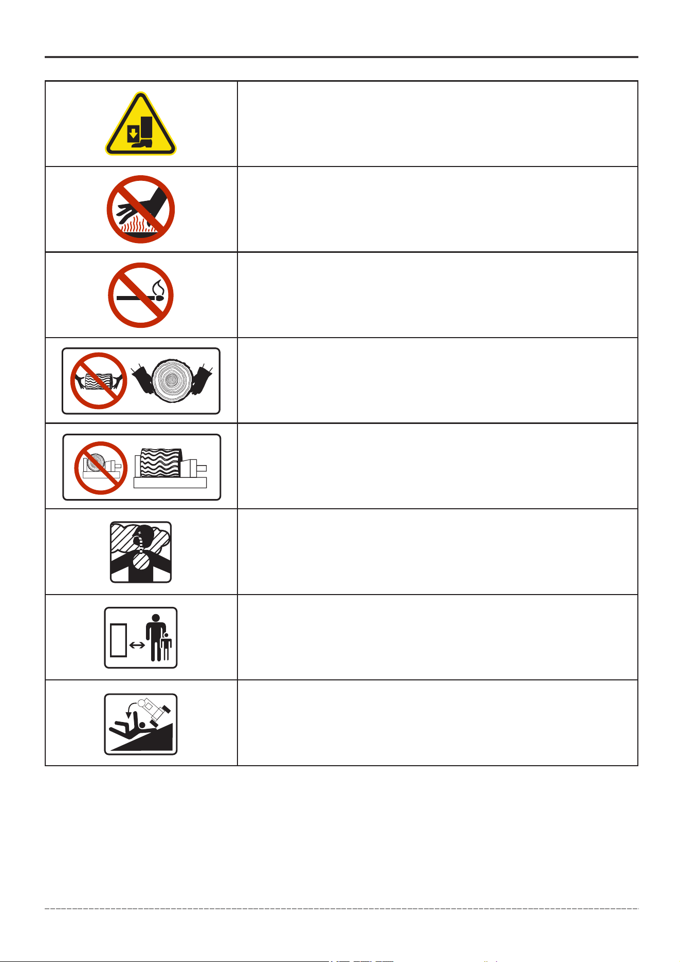
SIGNAL WORDS
DANGER WARNING CAUTION
Indicates a hazard
which, if not avoided,
will result in death or
serious injury.
Indicates a hazard
which, if not avoided,
could result in death
or serious injury.
Indicates a hazard
which, if not avoided,
could result in minor or
moderate injury.
Fire- Fuel and its vapors are extremely flammable which could
cause burns or fire resulting in death or serious injury.Engine
exhaust could cause fire resulting in death or serious injury.
Hot Surface- Muffler could cause burns resulting in serious injury.
Water contact with a power source could cause electrical shock
resulting in death or serious injury.
Safety Alert Symbol - Indicates a potential personal injury hazard.
Operator's Manual- Failure to follow warnings, instructions and
operator's manual could result in death or serious injury.
English Customer Service: 1-844-FIRMAN1
NOTICE
Indicates information
considered Important,
but not hazard-related.
INTRODUCTION
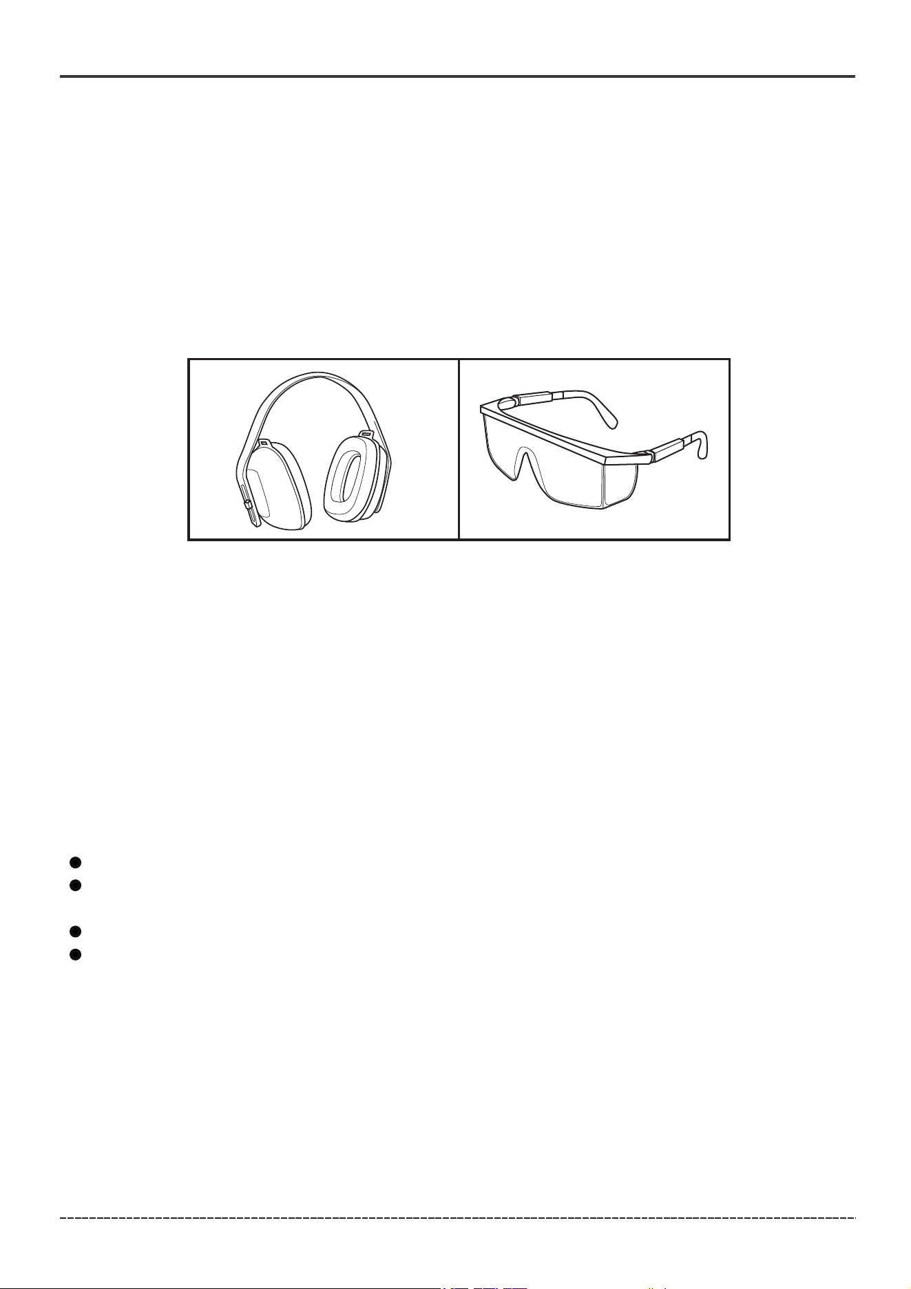
Eye and Ear Protection - Always wear safety goggles or safety
glasses with side shields, and as necessary a full face-shield as well
as full ear protection when operating this product.
Footwear - Always wear safety shoes or heavy boots when
operating the machine.
Gloves - Always wear nonslip, heavy-duty protective gloves when operating
this product.
Skin Injection Hazard - High pressure hydraulic oil can inject under your skin.
Make sure all fittings are tightly secure before applying pressure. Relieve
system pressure before servicing.
Always keep hands away from the wedge slide and the hydraulic cylinder.
Moving parts can crush or cut.
3
English Customer Service: 1-844-FIRMAN1
INTRODUCTION
Always keep feet away from the wedge slide and the hydraulic
cylinder. Moving parts can crush or cut.
Hot Surface- Muffler could cause burns resulting in serious
injury.
Open Flame alert - Fuel and its vapors are extremely flammable
and explosive. Keep fuel away from smoking, open flames,
sparks, pilot lights, heat, and other ignition sources.
Hold logs on sides when loading. Keep hands and feet away
from cylinder, wedge, and partially split logs.
Never place hands or any part of the body between a log and
any part of the log splitter.Do not split logs against the grain.
Split logs end to end in the direction of the grain only.
Toxic Fumes- Engine exhaust contains carbon monoxide,
a poisonous gas that will kill you in minutes. You cannot
smell it or see it.
Clearance - Keep all objects including others at least 10 feet
(3m) from this machine. Only one person should operate the
log splitter and load the logs.
Never operate on an incline. Make sure the log splitter is on a level
surface. Block tires and ensure support leg is secure to prevent
unintended movement of the log splitter during operation.

4
English Customer Service: 1-844-FIRMAN1
WARNING! This product can expose you to chemicals including gasoline engine
exhaust and lead and lead compounds, which are known to the state of California to
cause cancer, and carbon monoxide, which is known to the State of California to
cause birth defects or other reproductive harm. For more information go to
www.P65Warning.ca.gov.
INTRODUCTION
Training
1. Read the Operator’s Manual completely before attempting to use this log splitter.
2. Do not allow anyone to operate your log splitter who has not read the Log Splitter and Engine
manuals or has not been instructed on the safe use of the log splitter.
3. Never allow children or untrained adults to operate this machine.
4. Many accidents occur when more than one (1) person operates the log splitter. If a helper is
assisting in loading logs to be split, never actuate controls until helper is clear of the area.
5. Never allow anyone to ride on the machine.
6. Never transport cargo on the log splitter.
7. High fluid pressures are developed in hydraulic log splitters. Pressurized hydraulic fluid
escaping through a pin hole opening can puncture skin and cause sever blood poisoning.
Therefore, the following instructions should be heeded at all times.
7a. Do not operate the unit with frayed, kinked, cracked or damaged hoses, fittings, or tubing.
7b. Stop the engine and relieve hydraulic system pressure before changing or adjusting fittings,
hoses, tubing, or other system components.
7c. Do not adjust the pressure settings of the pump or valve.
7d. Do not check for leaks with your hand. Leaks can be detected by passing cardboard or wood
over the suspected area. Look for discoloration. If injured by escaping fluid, see a doctor at once.
Serious infection or reaction can develop if proper medical treatment is not administered
immediately.
8. Keep the operator zone and adjacent area clear for safe, secure footing.
9. The log splitter is equipped with a spark arrestor for use near unimproved forest, brush, or grass
covered land. Make sure you comply with local, state, and federal codes. Take appropriate fire-
fighting equipment with you. See engine manual for more information.
10. Log splitters should be used only for splitting wood. Do not use for other purposes unless the
manufacturer provides attachments and instructions.
11. Only split wood with the grain. NEVER split perpendicular to the grain.
12. Keep the area of operation clear of all persons, particularly small children.
Preparation
1. Be thoroughly familiar with all controls and with proper use of the equipment.
2. Safety Gear:
2a. Always wear safety shoes or heavy boots when operating the machine.
2b. Always wear safety goggles or safety glasses with side shields, and as necessary a full
face-shield when operating or servicing the machine.
2c. Never wear jewelry or loose-fitting clothing that might become entangled in moving or
rotating parts of the machine.
2d. Always wear full ear protection when operating the machine.
3. Make sure the log splitter is on a level surface. Block tires and ensure support leg is secure to
prevent unintended movement of the log splitter during operation.
3a. Always operate the log splitter from the manufacturer’s indicated operator zone.
4. Logs to be split on ram-type units should be cut as squarely as possible.

5
5. Fuel:
5a. Use an approved fuel container.
5b. Never add fuel to a running or hot engine.
5c. Fill fuel tank outdoors with extreme care. Never fill fuel tank indoors.
5d. Replace gasoline cap securely and clean up any spilled fuel. If fuel is spilled on clothing, change
clothing immediately.
5e. Never fill fuel containers inside a vehicle or on a truck or trailer bed with a plastic liner. Always
place container on the ground away from your vehicle before filling.
5f. Keep the fuel nozzle in contact with the rim of the fuel tank or container opening at all times
until fueling is complete. Do not use a nozzle lock open device.
English Customer Service: 1-844-FIRMAN1
INTRODUCTION
Operation
1. Be sure to confirm all hose connections and hose clamps are tight before each use. It is possible
for connections to vibrate loose over time.
2. Never leave the machine unattended with the engine operating.
3. Never operate the machine when under the influence of alcohol, drugs or medication.
4. The machine owner shall instruct all operators to read and understand the Log Splitter and
Engine manuals to ensure safe log splitter operation.
5. Always operate the log splitter with all safety equipment in place and all controls properly
adjusted for safe operation.
6. Always operate the log splitter at manufacturer’s recommended speed.
7. Always keep hands and feet clear of moving parts and partially split logs during the splitting
operation.
8. When loading a ram-type log splitter, place your hands on the sides of the log, not the ends.
Never place your hands or any part of your body between a log and any part of the log splitter.
9. On ram-type log splitters, never attempt to split more than one (1) log at a time unless the ram
has been fully extended and a second log is needed to complete the separation of the first log.
10. On ram-type log splitters on which the logs are not cut square, the longest portion of the log
should be rotated down and the most square end placed against the ram.
11. Only split logs with the grain of the wood.
12. Use only your hand to operate the log splitter controls.
13. Do not refuel until the engine has been turned off and cooled for at least 2 minutes. See engine
manual provided for more information.
Maintenance and Storage
1. Always shut off the engine while repairing or adjusting the log splitter except as recommended
by the manufacturer.
2. Clean debris and chaff from the engine cylinder, cylinder head fins, recoil starter cover, and muffler
areas. Clean engine muffler spark arrestor and inspect it regularly, replace if damaged. See engine
manual provided for more information.
3. Never store the unit indoors with fuel in the tank. Fumes might reach an open flame spark. Allow
the engine to cool before storing in any enclosure.
4. Clear debris from movable parts, but only when the engine is shut off.
5. Check to be sure all nuts and bolts are tight to assure the equipment is in safe working condition.
WARNING! Before starting and using this log splitter, read and follow all the on product labels and
safety information contained in the Log Splitter and Engine manuals. Failure to follow all on product
labels and manuals provided could result in death or serious injury to the operator or bystanders.
6
English Customer Service: 1-844-FIRMAN1
*We are always working to improve our products. Therefore, the enclosed product
may differ slightly from the image on this page.
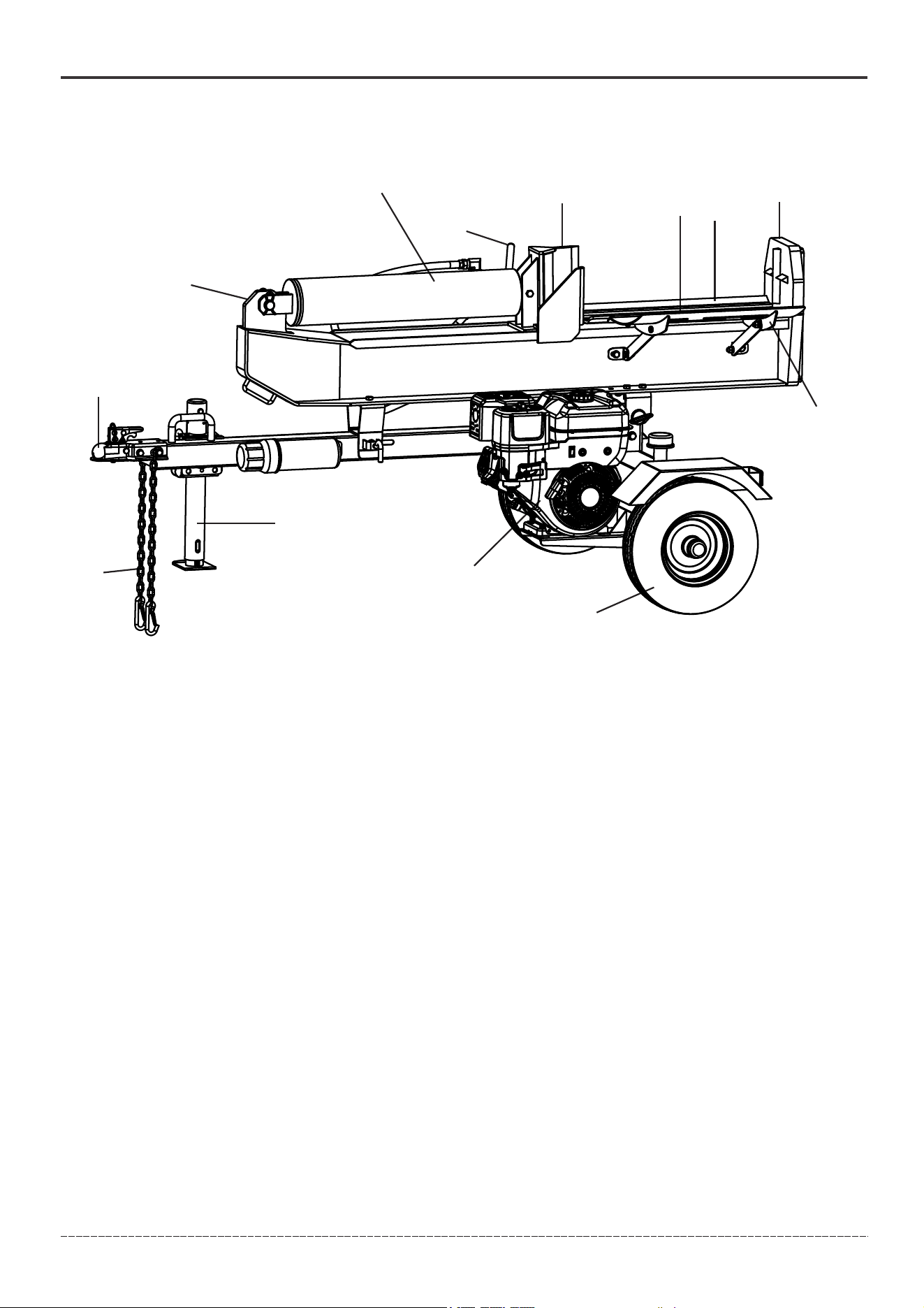
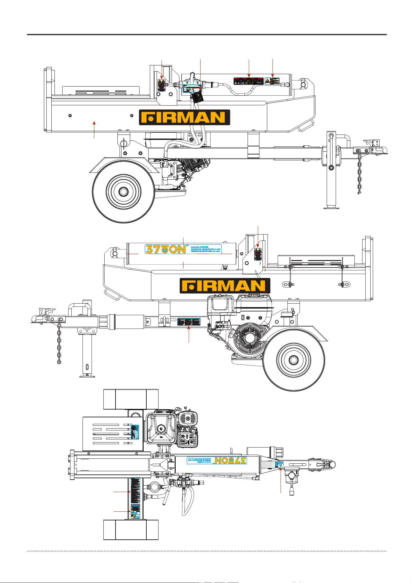
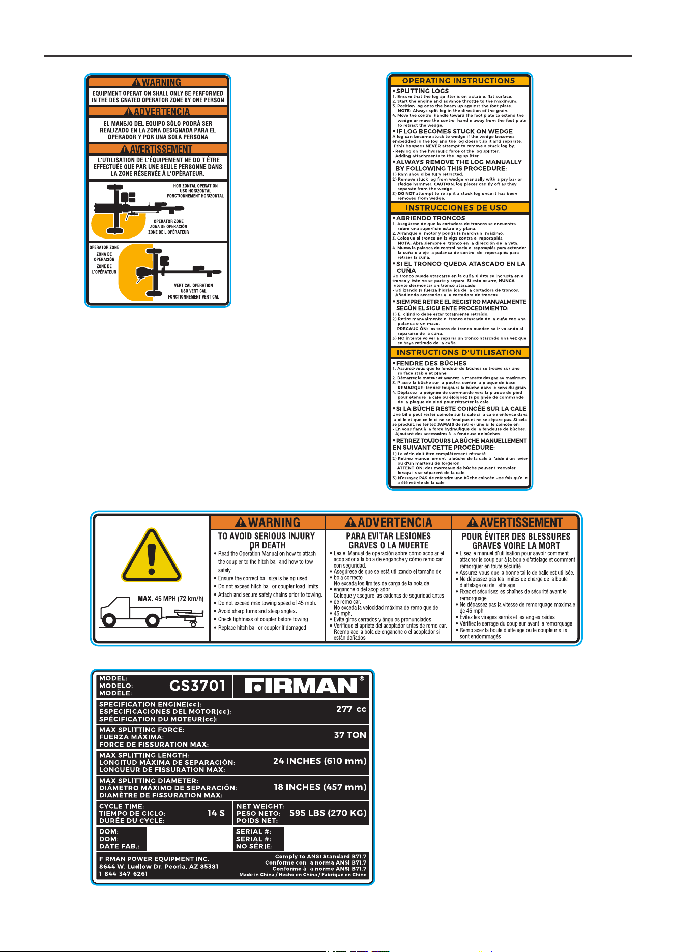
FEATURES, CONTROLS AND ON -PRODUCT HAZARD LABELS
Log Splitter
1. 2 in. (5.1 cm) Ball Coupler – For towing the log splitter behind your vehicle.
2. Mounting Plates – Holds hydraulic cylinder in place.
3. Hydraulic Cylinder – Converts hydraulic pressure into linear force.
4. Control Valve Handle – Controls the movement of the wedge slide.
5. Wedge Slide
6. Beam
7. Log Cradle – Prevents log from rolling off the beam.
8. Log Catcher
9. Tires – Maximum travel speed is 45 MPH (72 KM/H).
10. 277cc Kohler Engine
11. Support Leg – Supports log splitter while operating. This leg is adjustable. Before
using the unit, adjust this leg to make the machine horizontal. Raise leg for towing.
12. Safety Chains with Hooks – For use while towing.
13. Foot Plate
Splitting control The machine shall have an operator-presence control (OPC) for its splitting function.
For controls that move in the same direction as the ram or wedge, they shall move forward on
horizontal machines and down wardon vertical machines for the splitting action. Hand-operated
splitting controls (excludes power source controls) shall provide a minimum of 70 mm (2.75 in) of
clearance in all directions from the control and through out the operating range. The control’s
function and direction shall be identified by a durable label.
1
2
3
4
5
6
7
8
9
10
12
13
11
7
English Customer Service: 1-844-FIRMAN1
1
2
5
6
7
8
9
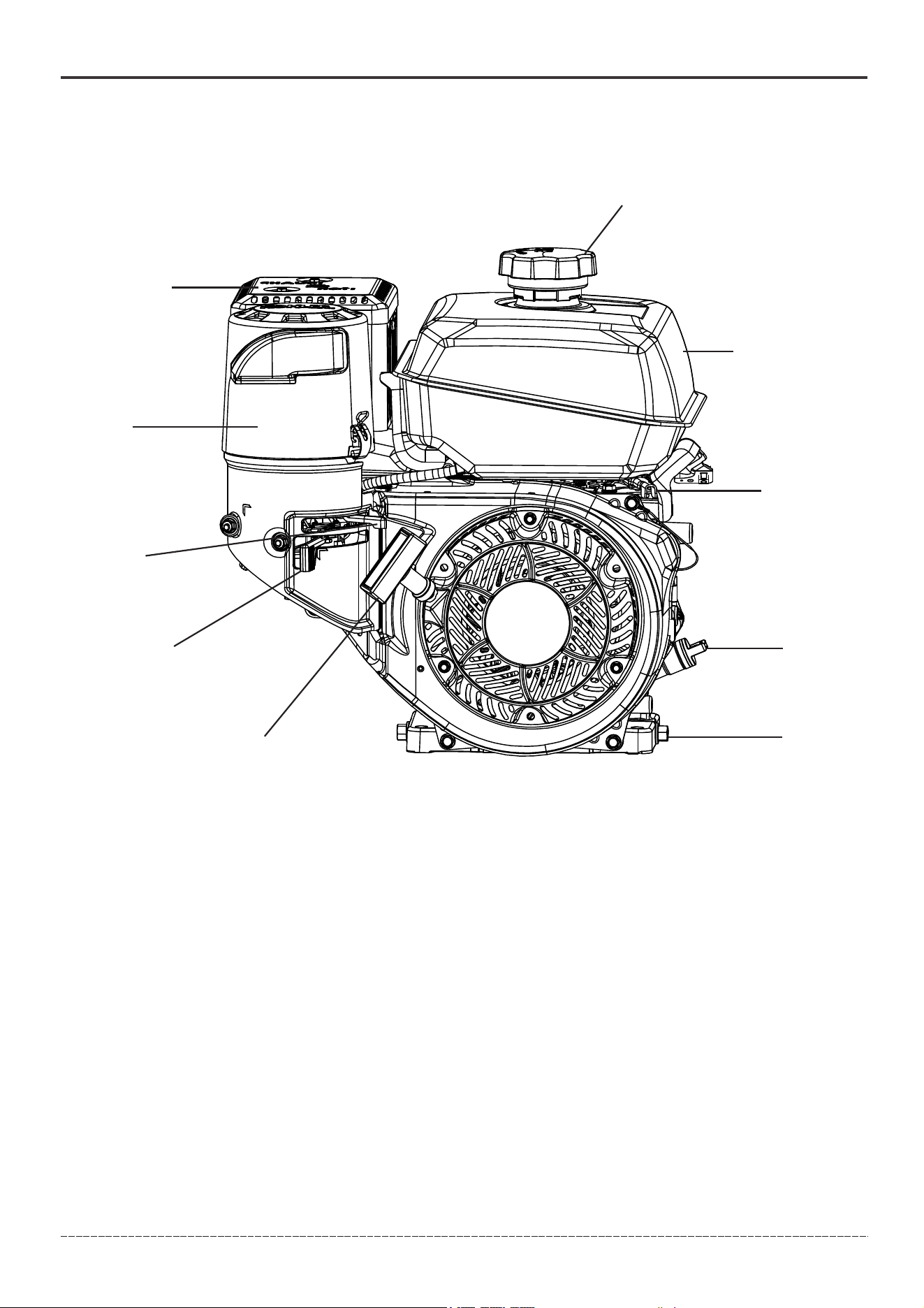
1. Fuel Cap
2. 1 Gal (3.8L) Fuel Tank
3.Throttle – Used to control the engine speed.
4. Oil Fill Cap/Dipstick – Used to check and fill oil level.
5. Oil Drain Bolt – Used to drain engine oil.
6. Recoil Starter – Used to manually start the engine.
7. Fuel Valve
8. Choke Lever - Used for cold engine starting.
9. Air Filter
10. Muffler
3
4
FEATURES, CONTROLS AND ON -PRODUCT HAZARD LABELS
Engine
For more information see Engine manual provided.
10
8
English Customer Service: 1-844-FIRMAN1
FEATURES, CONTROLS AND ON -PRODUCT HAZARD LABELS
⑩
①
②
①②⑩
③
④
①
⑤
⑥
⑦
⑧
⑨

9
English Customer Service: 1-844-FIRMAN1
FEATURES, CONTROLS AND ON -PRODUCT HAZARD LABELS
①
②
③
④
⑤
10
English Customer Service: 1-844-FIRMAN1
FEATURES, CONTROLS AND ON -PRODUCT HAZARD LABELS
⑥
⑦
⑧
⑨

11
English Customer Service: 1-844-FIRMAN1
Parts Included
FEATURES, CONTROLS AND ON -PRODUCT HAZARD LABELS
Part
Part Qty. Hardware Needed
Hardware
Qty.
Tool Needed
Manual Canister
Tow Bar
Fenders
Wheels
Beam
Engine
Hydraulic Hose
(Pump-Valve)
Oil Inlet Hose
Hydraulic Hose
(Valve-Tank)
Log Catcher
1
1
2
2
1
1
1
1
1
1
Accessories
– Engine Oil
– Hydraulic Oil
– Oil Funnel
- Spark Plug Wrench
- Teflon Tape
Bolt M6*20
Washer Φ6
Bolt M12*110
Washer Φ12
Lock Washer Φ12
Lock Nut M12
Bolt M6*20
Lock Nut M6
Castle Nut
Cotter Pin
Washer 3/4 in.
Axle Cap
Bolt M12*35
Washer Φ12
Lock Washer Φ12
Nut M12
R Pin
Hinge pin
Bolt M8*45
Base Mounting
Washer Φ8
Lock Nut M8
Washer Φ10
Lock Washer Φ12
Bolt M10*30
Screw M10*30
Nut M10
Spring Loaded Hose Clamp
3
3
2
4
2
2
4
4
2
2
2
2
6
6
6
6
1
1
4
4
8
4
4
4
4
2
4
1*10mm wrench or socket
1*18mm wrench or socket
1*18mm wrench or socket
1*10mm wrench or socket
1*10mm wrench or socket
1*30mm open-end wrench
Needle nose pliers
Mallet & Cap tool
1*18mm wrench or socket
1*18mm wrench or socket
1*13mm wrench
2*27mm open-end wrench
Clamp tool
2*27mm open-end wrench
1*16mm wrench or socket
Cross srewdriver
1*16mm wrench or socket
1*13mm wrench or socket
12
English Customer Service: 1-844-FIRMAN1
ASSEMBLY
Your log splitter requires some assembly. If you have any questions regarding the assembly of
your log splitter, call our help line at 1-844-347-6261. Please have your serial number and model
number available.
ASSEMBLY
Open Shipping Crate
1. Set the shipping crate on a solid, flat surface.
2. Carefully cut the shipping bands and remove lid of shipping crate.
3. Locate all hardware and components on GS3701 Parts Diagram and Parts List before beginning
assembly.
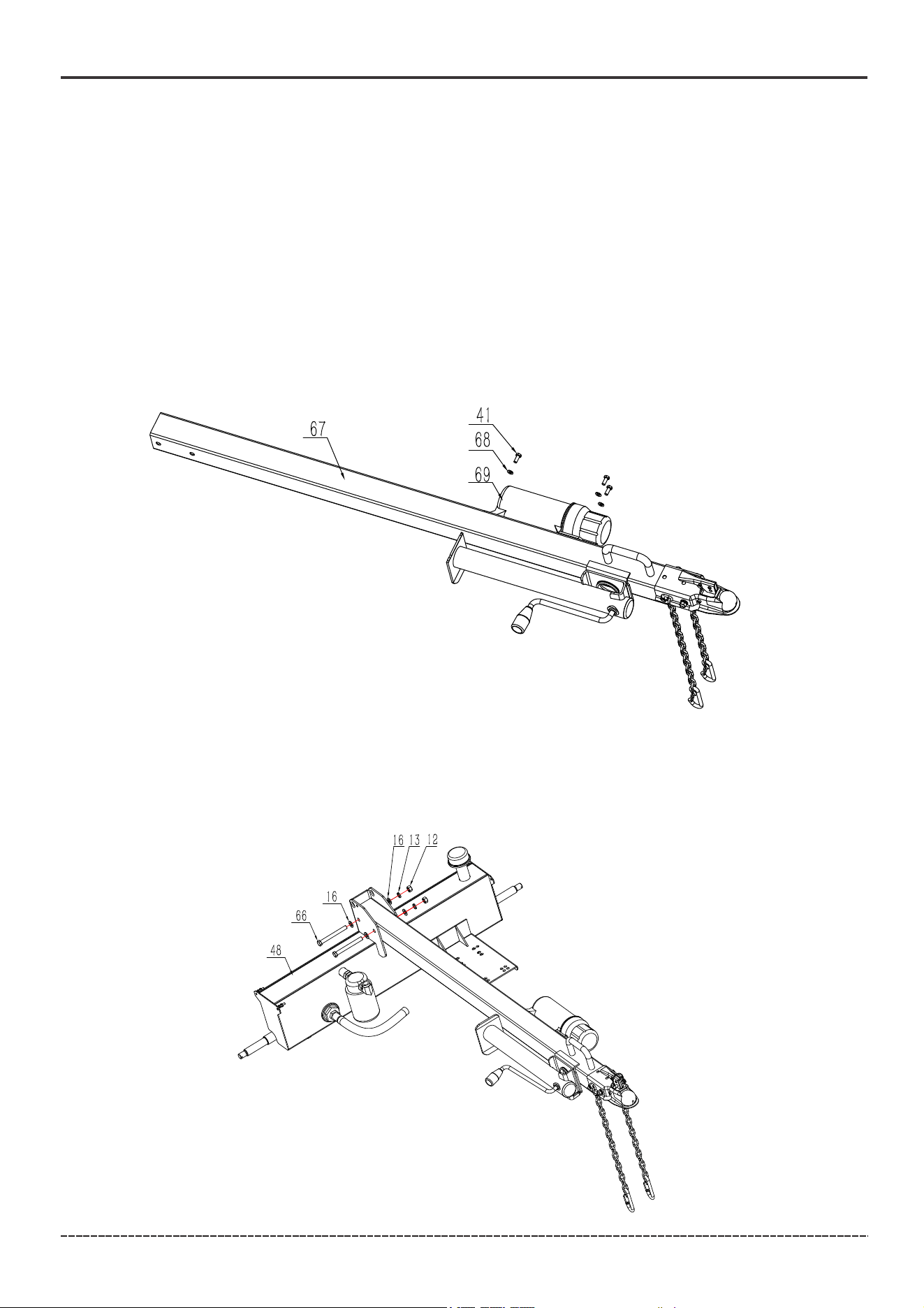
1. Install The Manual Canister
Attach the manual canister (69) to the tow bar (67) with three M6*20 bolts (41) and Ø6 washers (68).
2. Install The Tow Bar
Attach the tow bar (67) to the bracket on top of the hydraulic oil tank (48) with two M12 * 110 bolts
(66), Ø12 lock washer (13), M12 nuts (12) and four Ø12 washers (16).
13
English Customer Service: 1-844-FIRMAN1
ASSEMBLY
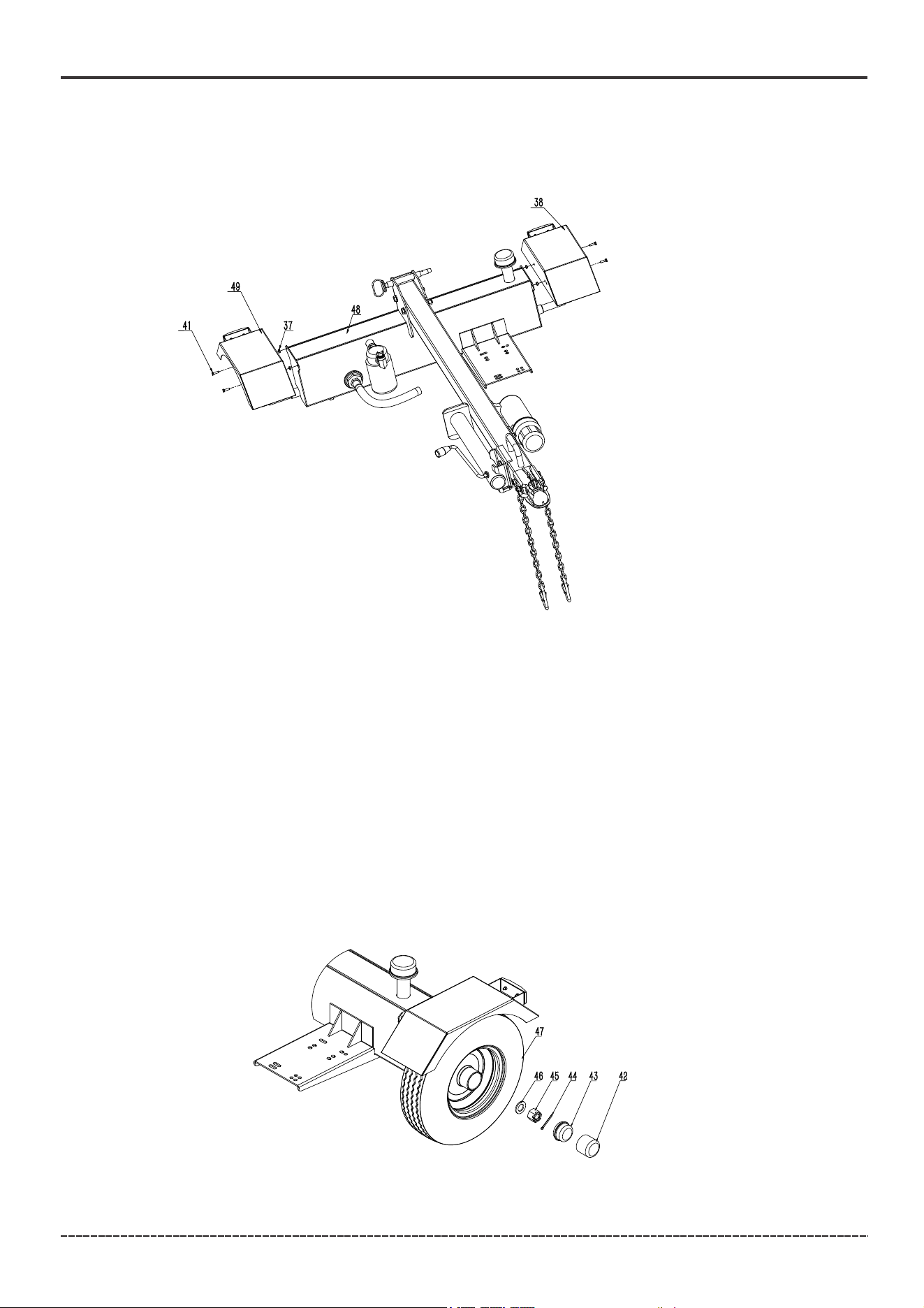
1. Remove disposable plastic spindle covers on axle ends and wheel bearing covers.
2. Slide wheel (47) on to the spindle with valve stem of tire facing outwards.
3. Install the 3/4 in. washer (46) onto the spindle.
4. Thread the castle nut 3/4 in. (45) onto the spindle. The castle nut should be driven down with a
socket only tightly enough to eliminate the free-play of the wheel assembly and not tighter. Make
sure that the wheel can freely rotate. The castle nut needs to be oriented to allow for the installation
of the cotter pin (44).
5. Install the cotter pin (44) through the castle nut 3/4 in. (45) and spindle. Bend pin ends around
spindle to secure its position.
6. Install the axle cap (43) using the cap tool (42). Gently tap on the cap tool (42) with a hammer to
drive the axle cap (43) into place.
7. Repeat with wheel on opposite side.
NOTICE Keep dirt and debris away from the wheel bearings during assembly.
3. Install The Fenders
1. Attach the left fender (49) to the side of the hydraulic oil tank (48) with two M6 * 20 bolts (41) and
M6 lock nuts (37). The safety reflector should be facing the back of the hydraulic oil tank (48).
2. Repeat with right fender (38) on opposite side.
4. Install the Wheels
Over-tightening the castle nut will cause the bearings to run hot and fail prematurely.
14
English Customer Service: 1-844-FIRMAN1
ASSEMBLY
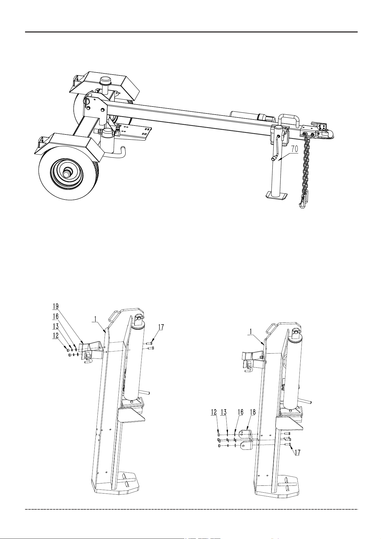
6. Install the Beam
Figure A
Figure B
5. Install The Support Leg
Unplug the pin and rotate the support leg (70) down , reinsert the pin .
1. Attach the locking device (19) to the beam (1) with two M12*35 bolts (17), Ø12 washers (16), Ø12
lock washer (13) and M12 nuts (12). As shown in Figure A.
2. Attach the connecting plate (18) to the beam (1) with four M12*35 bolts (17), Ø12 washers (16),
Ø12 lock washer (13) and M12 nuts (12). As shown in Figure B.
NOTICE Please use the two below holes for installation. If using an 18 "wheel, please use the two
above holes for installation.
15
English Customer Service: 1-844-FIRMAN1
ASSEMBLY
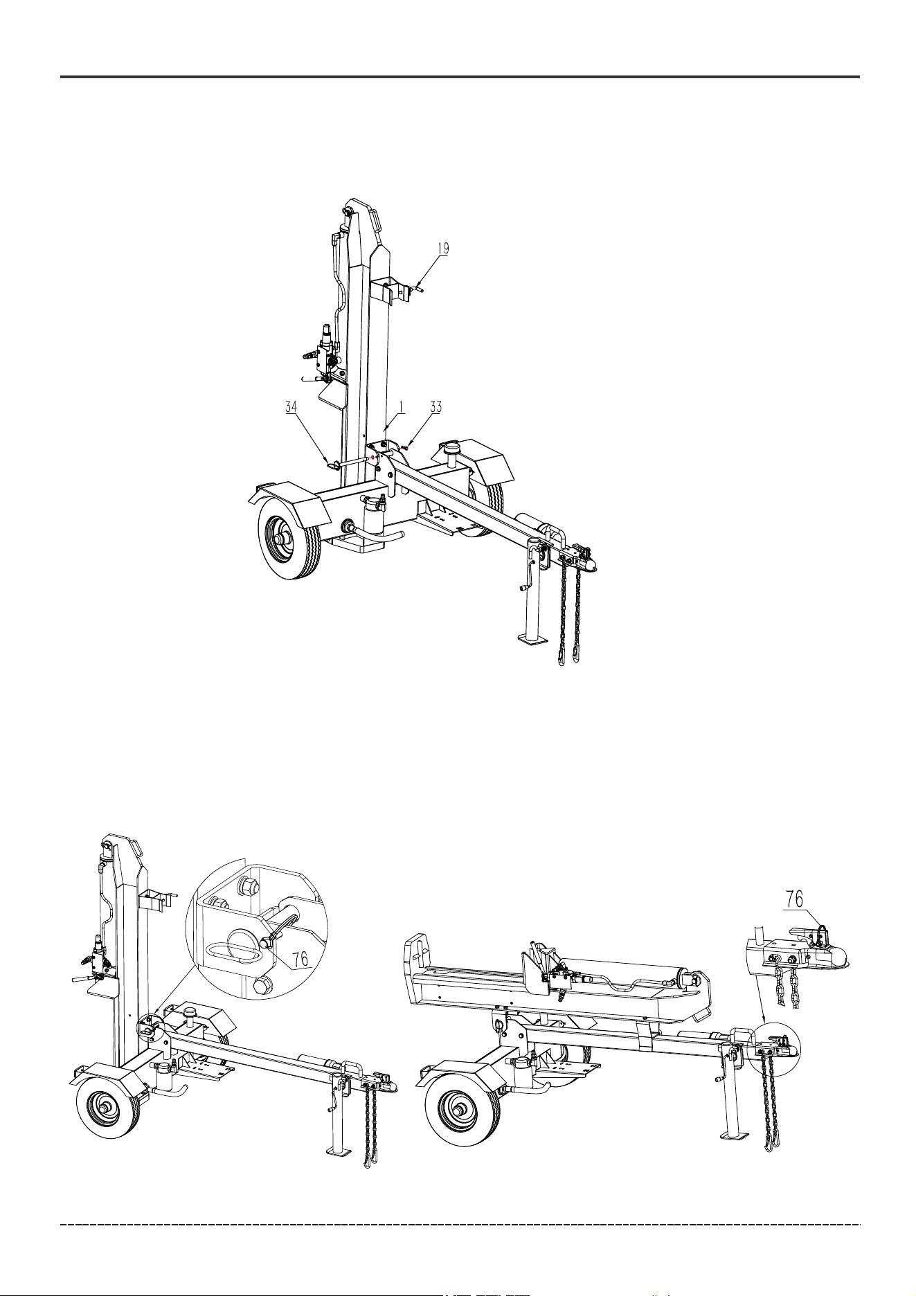
3. Stand the beam (1) vertical on the foot plate. Remove the R pin (33) and hinge Pin (34) from the
assembled unit.
4. Slowly back the assembled unit up to the beam (1). Insert the hinge Pin (34) and secure with R pin (33).
5. Unplug the pin on the locking device (19),pivot the beam (1) to the horizontal position, reinsert pin (19) .
NOTICE The pin (76) must move freely to be inserted or pulled.
– When in the vertical position, the location of the pin (76) is shown in figure C.
– When in the horizontal position, the location of the pin (76) is shown in figure D.
WARNING! The beam is extremely heavy and shall only be handled with 2 or more people.
To avoid muscle strain or back injury DO NOT try and lift or handle the beam without assistance.
Figure C Figure D
16
English Customer Service: 1-844-FIRMAN1
ASSEMBLY
NOTICE Shipping plugs must be removed from hydraulic pump prior to installing hoses.
The operating handle of the hydraulic valve may be tied during transportation, and the straps
need to be removed before installing the cylindrical pin(7.8) and pin(7.4).
NOTICE Pump-Valve Hydraulic Hose(High Pressure) and Valve-Tank Hydraulic Hose(Low Pressure)
Some hoses may be preassembled by the factory, check your hoses per below instructions to
ensure proper assembly.
– These hoses are black and have swivel nuts on both ends.
– The Pump-Valve Hydraulic Hose sends hydraulic oil from the pump to the control valve.
– The Valve-Tank Hydraulic Hose returns hydraulic oil from the control valve to the hydraulic oil tank.
Oil Inlet Hose
– This is the clear hose that connects the hydraulic oil tank to the pump inlet.
Secure both ends of hose with hose clamps.
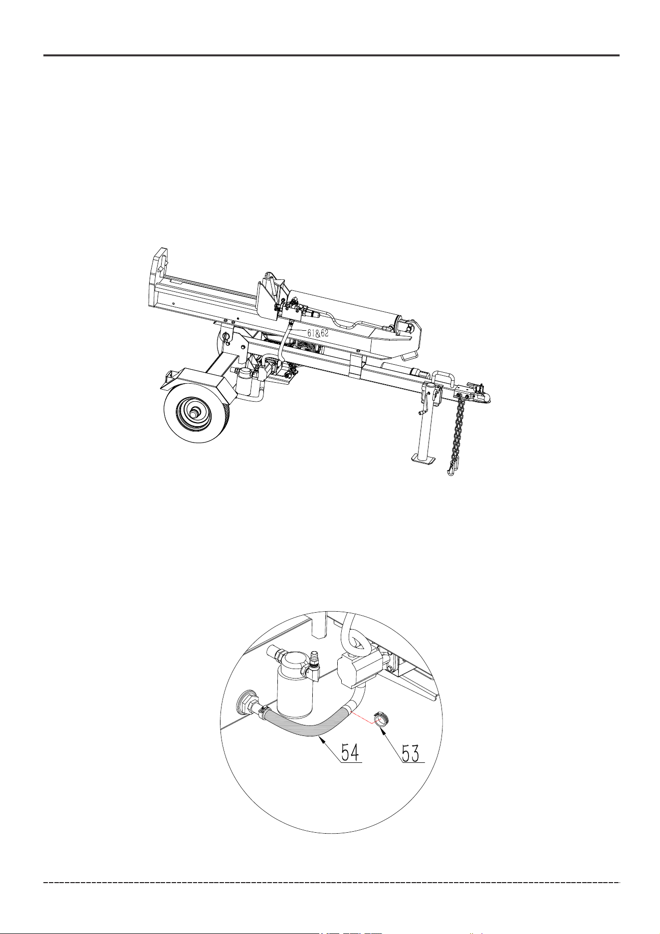
8. Install the Hoses
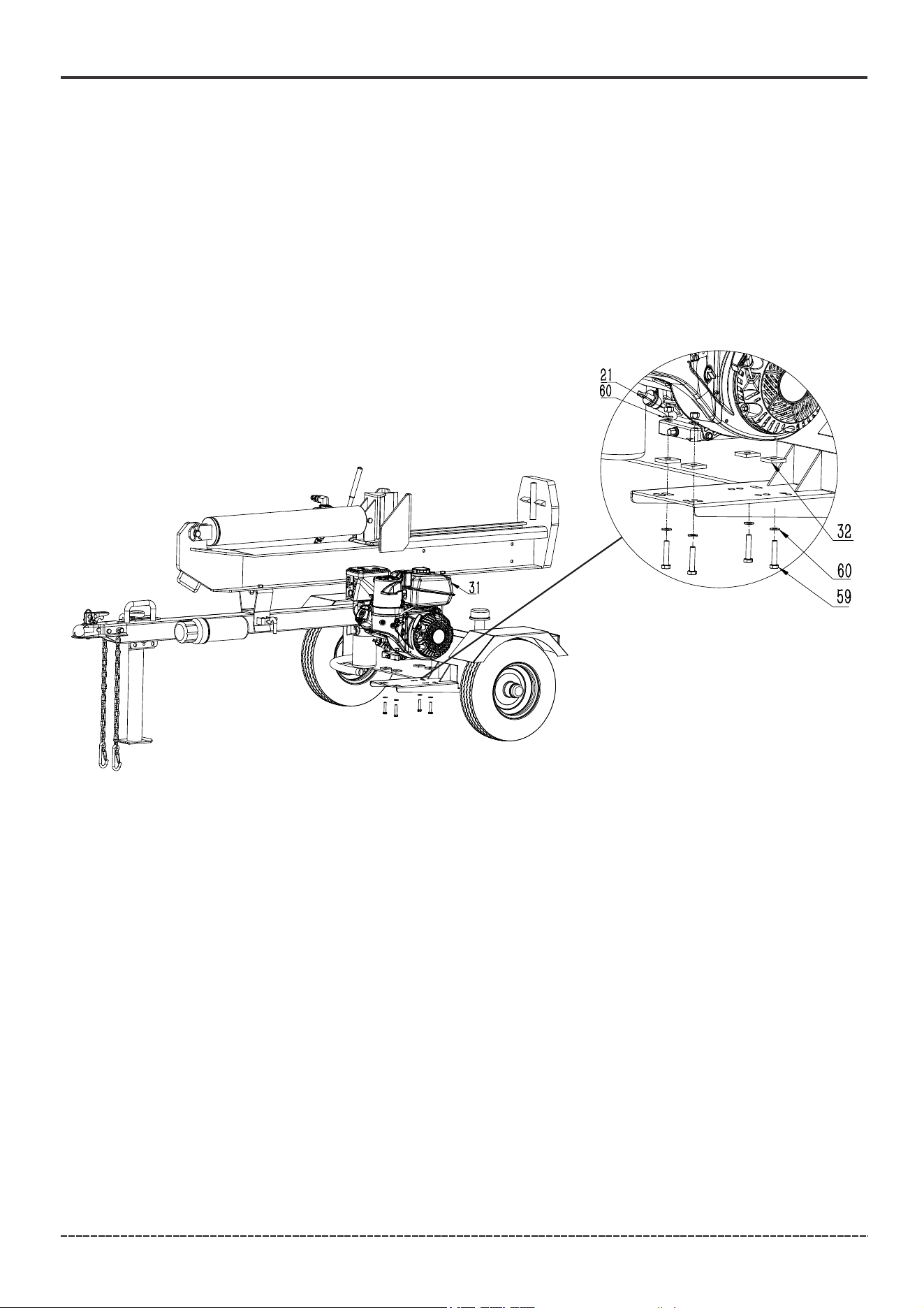
7. Install The Engine
1. Place the engine (31) and base mounting (32) on the engine mounting platform with the recoil
cover facing outward towards the wheel, and align the four holes on the engine base with the
holes on the engine platform.
2. Install a M8*45 bolt (59)、a Ø8 washer (60) up through the hole on the engine platform and
through the hole on the engine base.
3. Place a Ø8 washer (60) on the M8*45 bolt (59) and thread a M8 lock nut (21) onto the bolt and
tighten securely. Tighten to 5.9 lbf-ft - 7.4 lbf-ft (8-10 N.m) or fully.
4. Repeat steps 2 and 3 for the remaining bolts, washers and lock nuts. As shown in Figure E.
Figure E
17
English Customer Service: 1-844-FIRMAN1
ASSEMBLY
Using the provided hose clamps, connect one end of the oil inlet hose (76) to the port on the
hydraulic oil tank (C) next to the oil return filter and the other end to the pump inlet on the side of
the pump (D). Securely tighten the clamps on both ends of the suction hose with either a flat head
screw driver or 8mm socket. Torque to 2.9 lbf-ft - 4.4 lbf-ft (4-6 N.m).
Oil Inlet Hose
Hydraulic Hose (Pump-Valve)
Connect the pump-valve hydraulic hose with sheath (61&62) to the pump outlet first, then the valve
inlet.
NOTICE Prior to assembly apply the teflon tape provided to the pump end only of the pump-valve
hydraulic hose threads (61). Teflon tape should be wrapped in the same direction as the threads.
As you wrap the Teflon tape, move the tape to cover new threads and overlap half of the piece
below it. When you reach the end of the threads pull the tape tightly to break it off the roll. Wrap
the threads a total of two to three times before assembly.
Securely tighten both ends of the high pressure hydraulic hose with two 27mm open-end wrenches.
Tighten to 44 lbf-ft – 52 lbf-ft (60-71 N.m).
Using the provided hose clamps, attach oil inlet hose (54) to hydraulic pump. Securely tighten the
clamp (53) on the end of the oil inlet hose (54) with either a flat head screw driver. Torque to
2.9 lbf-ft – 4.4 lbf-ft (4-6 N.m).
18
English Customer Service: 1-844-FIRMAN1
ASSEMBLY
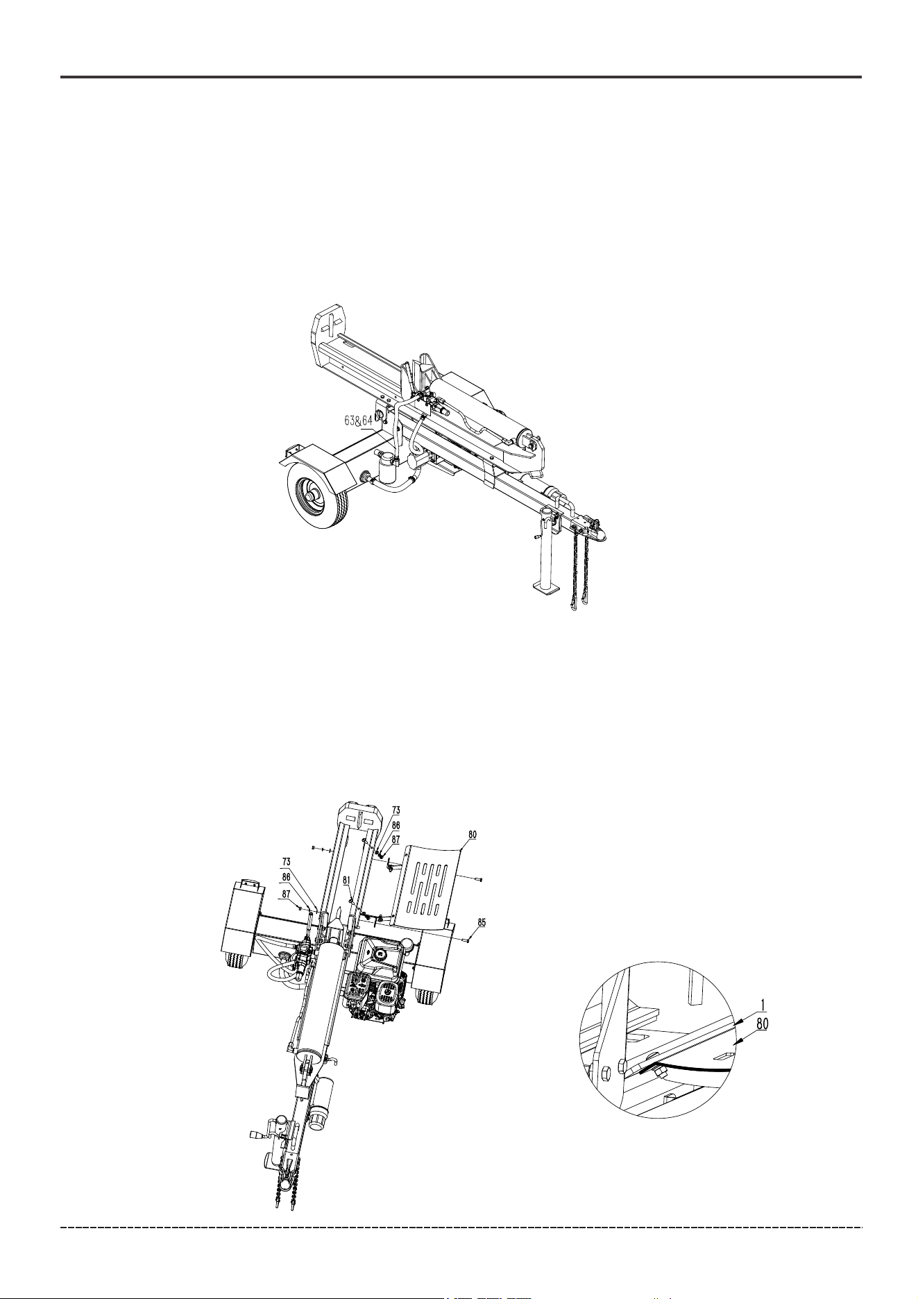
9. Install the Log Catcher
Hydraulic Hose (Valve-Tank)
Connect the valve-tank hydraulic hose with sheath (63&64) to the oil return filter first, then the valve
outlet.
NOTICE Prior to assembly apply the teflon tape provided to the oil return filter end only of the
valve-tank hydraulic hose threads (63). Teflon tape should be wrapped in the same direction as the
threads. As you wrap the Teflon tape, move the tape to cover new threads and overlap half of the
piece below it. When you reach the end of the threads pull the tape tightly to break it off the roll.
Wrap the threads a total of two to three times before assembly. Securely tighten both ends of the
hydraulic hose with two 27mm open-end wrenches to 52 lbf-ft – 66 lbf-ft (71-90 N.m).
1. With the log catcher (80) angled upward, align the four holes on the log catcher with the four
threaded holes on the splitter beam.
2. Place Ø 10 washers (73) and Ø 10 lock washers (86) onto the two M10*30 bolts (85) onto the
M10*30 screws (81) . Thread them through the holes on the log catcher (80) and into the holes on
the splitter beam and tighten securely.
NOTICE The log catcher (80) should be installed on the lower side of the log cradle of the beam (1).
19
English Customer Service: 1-844-FIRMAN1
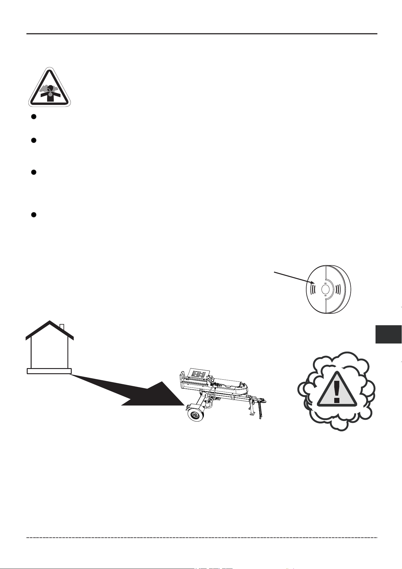
1. Location
DANGER! Engine exhaust contains carbon monoxide, a poisonous gas that could kill
you in minutes. You CANNOT smell it, see it, or taste it. Even if you do not smell exhaust
fumes, you could still be exposed to carbon monoxide gas.
Carbon Monoxide Alarm(s)
Install carbon monoxide alarms inside your home. Without working
carbon monoxide alarms, you will not realize you are getting sick and
dying from carbon monoxide poisoning.
20 ft. (6 m) min.
OPERATION
Install battery-operated carbon monoxide alarms or plug-in carbon monoxide alarms with
battery back-up according to the manufacturer's instructions. Smoke alarms cannot detect
carbon monoxide gas.
Do not run this log splitter inside homes, garages, basements, crawlspaces, sheds, or other
partially enclosed spaces even if using fans or opening doors and windows for ventilation.
Carbon monoxide can quickly build up in these spaces and can linger for hours, even after this
product has shut off.
If you start to feel sick, dizzy, weak or your home’s carbon monoxide alarm sounds, get to fresh air
right away. Call emergency services. You may have carbon monoxide poisoning.
Prevent Carbon Monoxide (CO) Poisoning
Use outdoors and downwind at least 20 ft. (6 m) from any home.
Point exhaust away from all homes and occupied spaces.
Install CO alarms inside your home.
Operate log splitter only outdoors and downwind at least 20 ft.(6 m) from occupied spaces with
exhaust pointed away to reduce the risk of carbon monoxide accumulating.

20
English Customer Service: 1-844-FIRMAN1
Reduce Risk of Fire
WARNING! Exhaust heat/gases could ignite combustibles, structures or damage fuel
tank causing a fire, resulting in death or serious injury.
OPERATION
5 ft.(1.5 m)
min.
5 ft.(1.5 m)
min.
20 ft.(6 m) min.
Keep log splitter at least 5 ft. (1.5 m) from any structure, trees or vegetation over 12 in. (30 cm)
in height.
Select an outdoor site that is dry and protected from the weather. Do not move log splitter
indoors to protect it from the weather.
Do not locate the log splitter under a deck or other similar structure that may confine heat and
airflow.
21
English Customer Service: 1-844-FIRMAN1
2. Oil and Gasoline
Add Engine Oil
NOTICE Do not attempt to crank or start the engine before it has been properly filled with the
recommended type and amount of oil. Damage due to operation with no oil will void your warranty.
Degrees Celsiusº(Outside)
Full Synthetic 5W-30
Degrees Fahrenheitº(Outside)
5W-30 10W-40
10W-30
1.Place log splitter on a flat, level surface.
2.Clean area around oil fill and remove yellow oil fill cap/dipstick.
3.Wipe dipstick clean.
OPERATION
(H)
DRAIN PLUG
(L)
H
L
1. Place log splitter on a flat, level surface.
2. Using oil funnel provided
3. See engine manual provided for instructions.
Oil Sentry™
The engine is equipped with Oil Sentry™ a switch designed to prevent engine from starting in a
low oil or no oil condition. Oil Sentry™ may not shut down a running engine before damage occurs.
See engine manual provided for more information.
Add Gasoline
WARNING! Fuel and its vapors are extremely flammable which could cause burns or fire
resulting in death or serious injury.
Turn engine OFF and let it cool at least 2 minutes before removing fuel cap.
Do Not refuel or move log splitter when engine is running.
Move log splitter outdoors prior to adding or draining fuel.
Keep fuel away from any ignition sources.
Do not overfill tank, allow space for fuel expansion.
If any fuel spills, wait until it evaporates before starting engine.
Check and replace fuel lines, tank, cap, and fittings prior to each use if any damage or leaks
are found.
See engine manual provided for filling instructions, fuel requirements, fuel line, and safety
information.
22
English Customer Service: 1-844-FIRMAN1
OPERATION
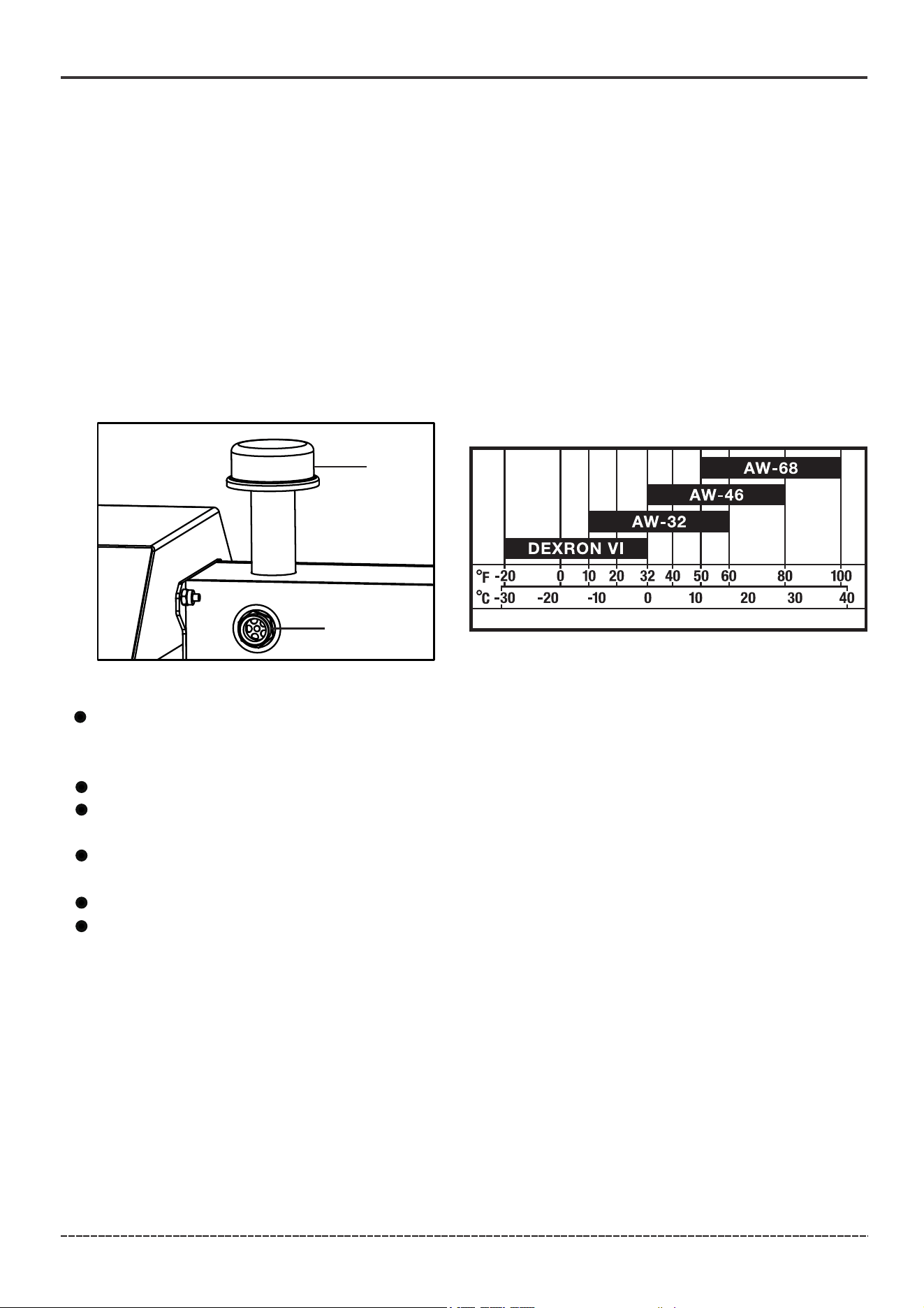
Add Hydraulic Oil
1. Make sure the log splitter is on a flat, level surface.
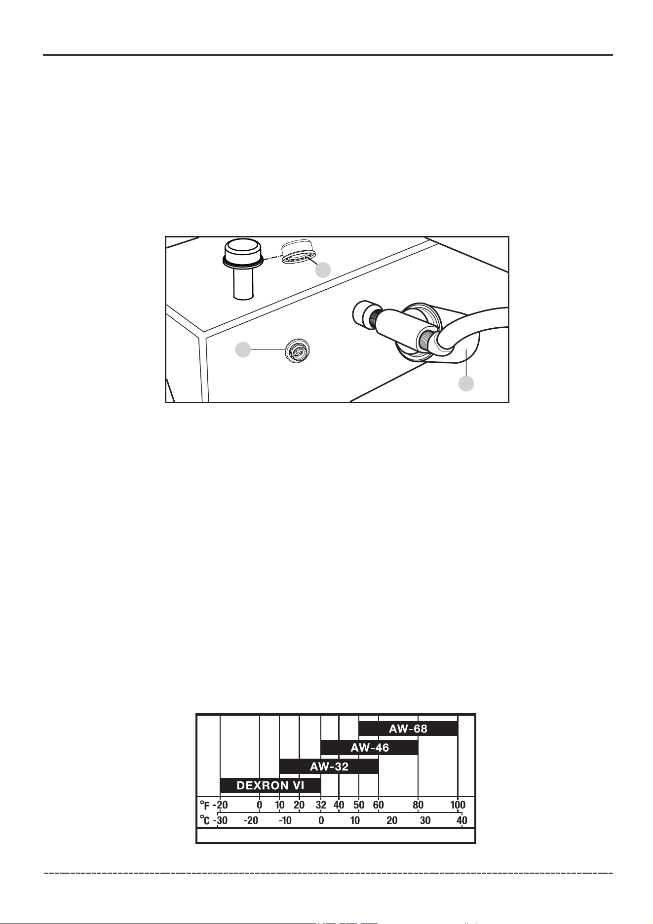
2. Remove the oil fill cap(A) from the hydraulic oil tank.
3. Add 5 gal. (19 L) of hydraulic oil. AW32, AW46, AW68 & universal hydraulic oil are all acceptable types
of fluid. Automatic transmission fluid can be used when operating in temperatures below 32°F (0°C).
4. Check the hydraulic oil level using the oil sight glass (B). Oil level should visibly fill the sight glass .
5.Replace and tighten the oil fill cap(A) .
6.Start engine and use the control valve handle to extend and retract wedge slide several times
to remove air from the lines.
7. Check the oil sight glass(B) and add approximately 1.8 gal.(6.8 L) of hydraulic oil to bring the oil
level back up to the oil sight glass (B). Do Not overfill.
8.Check oil level daily and add as needed.
High fluid pressure and temperatures are created in the hydraulic log splitter.
Inspect hydraulic system regularly for possible leaks. Never check for leaks with your hand while
the system is pressurized. Seek medical attention immediately if injured by escaping fluid.
Make sure all fittings are tight and secure before applying pressure. Relieve system pressure
before servicing.
Make sure the hydraulic hoses do not touch any hot surfaces or cutting areas.
Hoses need to be positioned were they are clear from the engine and cutting wedge. To avoid
death or serious injury always inspect the hoses before operating the log splitter.
WARNING! Failure to follow these instructions could result in death or serious injury.
DO NOT remove the hydraulic oil fill cap when the engine is running or oil is hot. Hot oil can escape
causing severe burns. Always allow the log splitter to cool completely before removing the hydraulic
oil fill cap(A).
A
B
C
A
B

23
English Customer Service: 1-844-FIRMAN1
OPERATION
Before Each Use Inspect the Log Splitter
WARNING! Before operating or using the log splitter, read and follow the instructions below
and all safety information. Failure to follow these instructions could result in death or serious
injury.
ALWAYS use the log splitter for its intended use.
ONLY use the log splitter to split wood logs, length wise with the grain.
NEVER modify, alter or change the log splitter in any way, modifications will void the warranty.
NEVER attach a rope, cable or other device to the control lever on the log splitter.
Only operate the log splitter in daylight or good artificial light.
NEVER leave the log splitter unattended while the engine is running.
DO NOT change the splitting position with the engine running. Contact with the muffler can
cause serious burns.
ALWAYS make sure the beam is in the locked position.
DO NOT let the beam drop as it could crush fingers or cause damage to the log splitter.
NEVER operate or let anyone else operate, the log splitter while under the influence of alcohol,
drugs, or medication.
1. Check the hydraulic oil level and visually inspect all hoses, attachments and cylinder for loose
fittings, leaks, cracks, fraying or other damage.
2. DO NOT operate the log splitter if there is any indication of damage.
3. Inspect the engine and make sure the oil level is correct before operating. Clean and Inspect the
spark arrestor regularly (follow all engine manual scheduled maintenance instructions).
4. The tires need to be fully inflated and in good repair. Reference the tire sidewall for recommended
tire pressure.
WARNING! Before towing the log splitter, read and follow the instructions below and all safety
information. Failure to follow these instructions could result in death or serious injury.
Making sure the Log Splitter is securely attached to the vehicle is the responsibility of the
owner/operator.
Failure to securely attach the Log Splitter can cause loss of control of the vehicle or the log
splitter being separated from the towing vehicle.
Move the fuel shutoff to “OFF” before towing the log splitter.
DO NOT over inflate tires. Serious injury can result if tires fail.
DO NOT tow the log splitter if the tires are worn or will not hold air.
DO NOT exceed the maximum 45 MPH (72 KM/H) towing speed and check local, state, and
federal requirements before towing on any public road.
Always use safety chains. Secure and lock the log splitter to the vehicle hitch before moving.
Drive safely. Be aware of the added length of the log splitter. When backing up, using a spotter
outside the vehicle is recommended.
Never ride or transport cargo on the log splitter.
Turn off the vehicle before leaving the log splitter unattended.
Block the log splitter wheels to prevent unintended movement.
ALWAYS disconnect your log splitter from the towing vehicle before operating it.
24
English Customer Service: 1-844-FIRMAN1
OPERATION
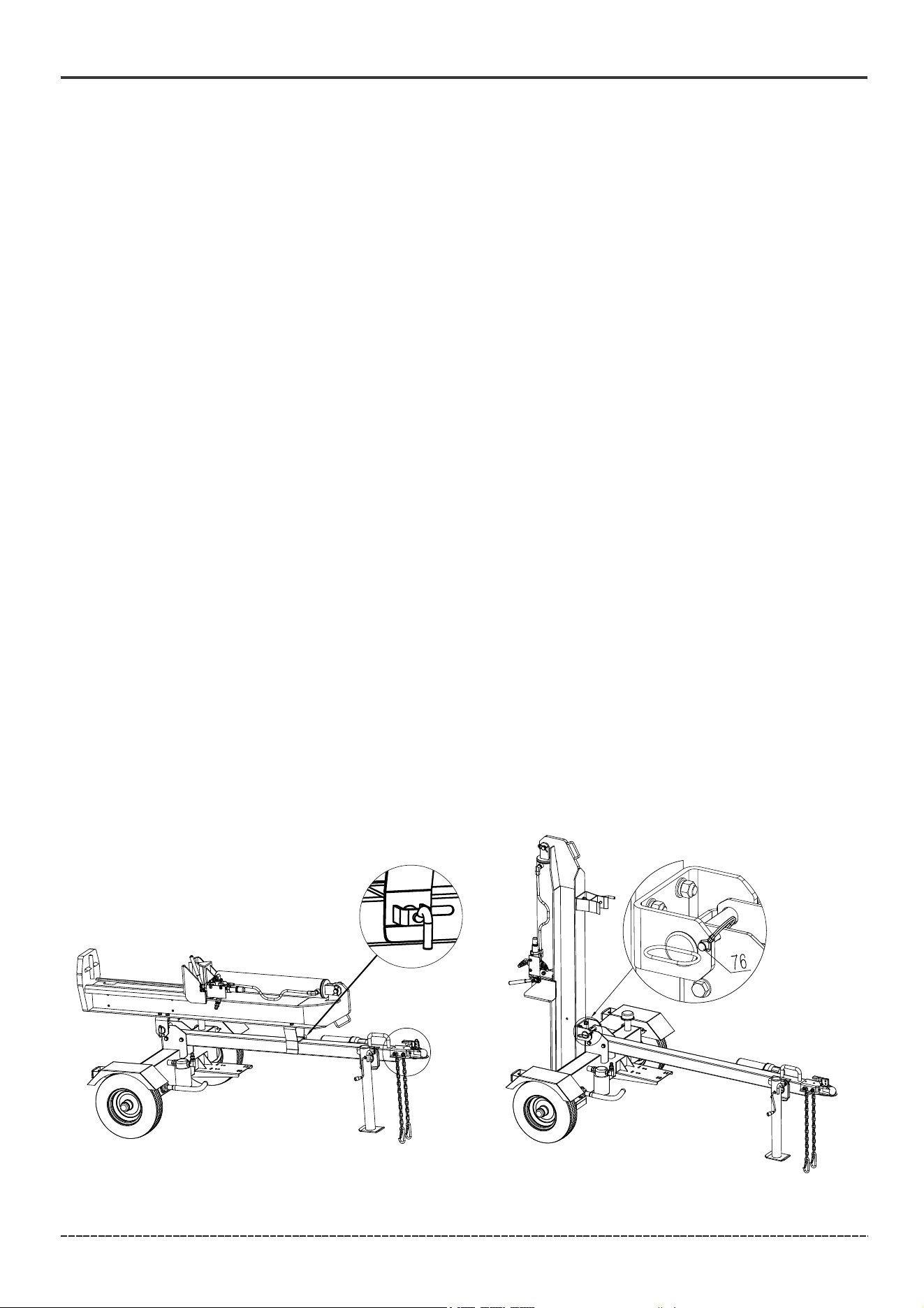
Changing Beam from Horizontal to Vertical Orientation
When logs are too heavy to lift, the log splitter beam can be changed to the vertical orientation.
Always allow the log splitter to cool completely before changing from horizontal to vertical
orientation.
To change from horizontal to vertical orientation:
1. Remove horizontal beam pin that locks the beam to the tow bar (figure A).
2. Standing alongside the hydraulic cylinder, (opposite side from the engine) firmly grasp the
handle on the beam and lift upward while pushing the beam back until upright. Once the beam is
upright lock the beam (figure B).
To change from vertical to horizontal orientation, reverse steps.
Figure A Figure B
NOTICE When attaching the Safety Chains, Attach the left chain to the right anchor of the tow
vehicle and the right chain to the left anchor of the tow vehicle so that the Safety Chains cross
each other under the Ball Hitch.
5. Insert the pin(76) into the hole in the Latch Assembly.
1. Lower the beam to its horizontal position. Make certain the beam is locked securely with the horizontal
beam pin.
2. Change the Jack Stand to transporting position.
a) Pull out the support leg pin .
b) With the help of another person, Support the Tow Bar and pivot the support leg up to the transporting
position.
c) Secure with the support leg pin previously pulled out.
3. Pull the Latch Assembly on the Receiver up and into the open position. Position the Receiver of the Log
Splitter over and onto the tow vehicle’s 2" (51 mm) tow ball.
4. Close the Latch Assembly on the Receiver to lock it onto the Tow Ball. Attach the towing Safety
Chains to the tow vehicle ensuring there is enough slack for turning.
Transporting the Log Splitter
WARNING! The beam is extremely heavy and shall only be handled with 2 or more people. To avoid
muscle strain or back injury, DO NOT try and lift or handle the beam without assistance.
25
1. Before using the log splitter, check for loose or missing parts and for any damage which may
have occurred during shipment. Ensure spark plug, muffler, fuel cap, and air cleaner are all in place.
2. Move log splitter outdoors to safe operating location downwind and at least 20 feet from any
occupied spaces.
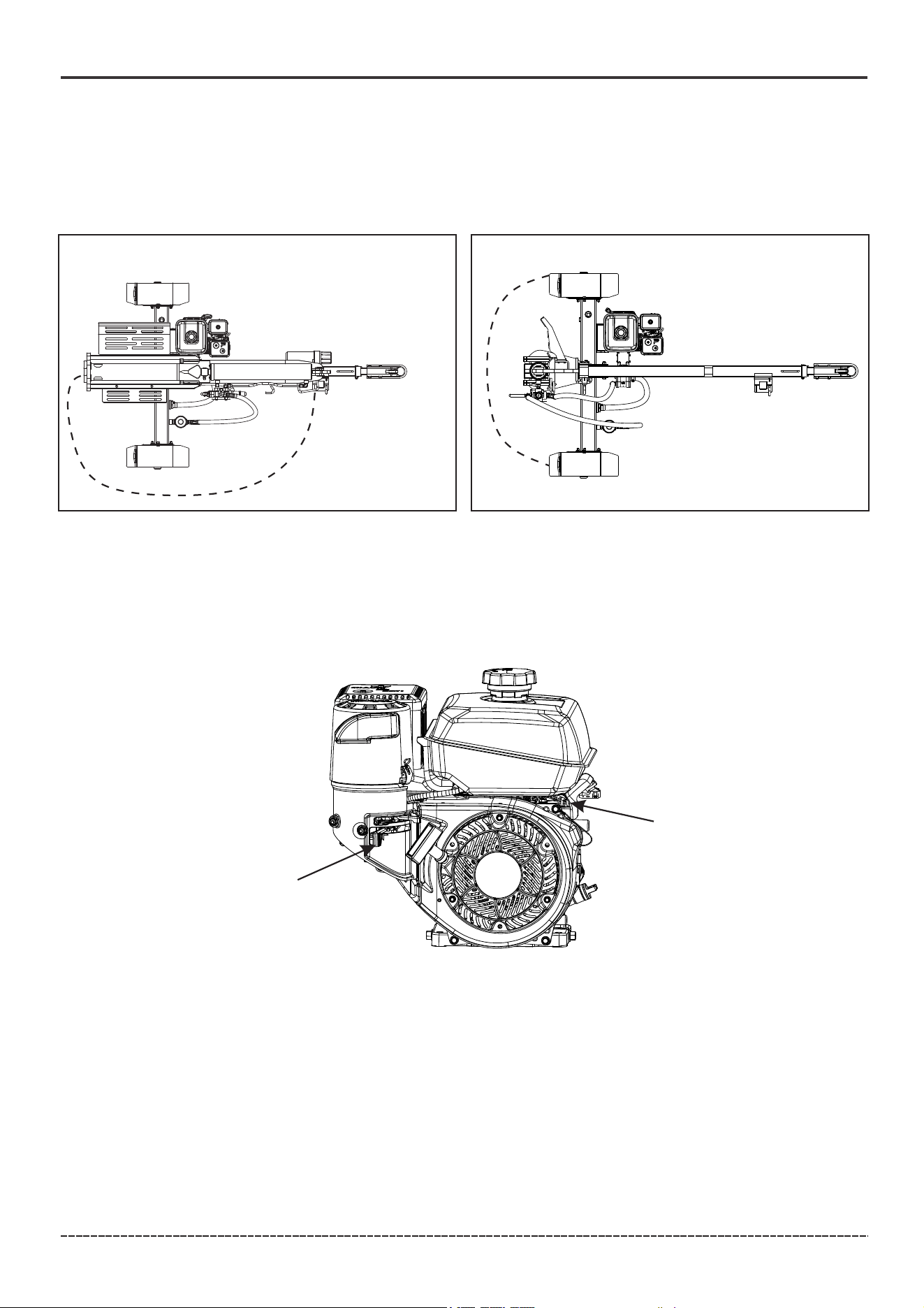
3. Turn fuel shut-off valve(B) to ON position .
2. Turn engine on/off switch(A) to “ON”(I) position .
3. Start engine as follows:
Cold engine: Place throttle control(D) midway between SLOW and FAST positions. Place choke
control into ON position.
Warm engine: Place throttle control(D) midway between SLOW and FAST positions. Return choke
to OFF position as soon as engine starts. A warm engine usually does not require choke on.
4. Slowly pull starter handle until just past compression-STOP! Return starter handle; firmly pull
straight out to avoid excessive rope wear from starter rope guide.
5. Gradually return choke control to OFF position after engine starts and warms up.
Engine/equipment may be operated during warm up period, but it may be necessary to leave
choke partially on until engine warms up.
NOTICE: For more information, please refer to the Kohler engine manual.
English Customer Service: 1-844-FIRMAN1
OPERATION
A
Starting the Engine
The log splitter must have at least 5 feet of clearance from combustible material. The log splitter
needs to be on a dry and level surface with good footing. Do not work in mud, ice, brush or snow.
When using the log splitter the operator zone must be maintained at all times.
Only operate log splitter from operator zone shown below.
OPERATOR
ZONE
Horizontal
Vertical
OPERATOR
ZONE
See engine manual provided for engine starting and stopping instructions, cold weather starting
hints, angle of operation, engine speed, high altitude operation and safety information.
Always ensure that the Fuel Valve is in the “OFF” position when the engine is not in use.
B
26
English Customer Service: 1-844-FIRMAN1
Stopping the Engine
1. Move throttle control (A) to slow position.
2. Move the fuel valve (B) to the "OFF" position.
Always ensure that the Fuel Valve is in the “OFF” position when the engine is not in use. See engine
manual provided for more information.
OPERATION
After pump has cooled, remove the priming plug and pump drain plug and allow the pump to
drain thoroughly.
NOTICE Drain water from pump after use. Trapped water could freeze and damage pump. Pump
damage caused by freezing is not covered by warranty.
After each use:
1. Drain pump housing.
2. Disconnect and drain hoses.
3. Clean pump with dry cloth.
4. Store pump in clean, dry area.
5. If storing for more than 30 days, see long term storage.
AFTER EACH USE
Flush the pump with clean water after each used is advised. This will help to extend the life of the
pump as some materials pumped may leave residue that could corrode parts, build up over time,
or cause harm to any plants, animals or humans. Flushing the pump will help to reduce any damage
and dangers caused by pumping chemicals and pesticides.
Log Splitter Operation
1. ALWAYS wear eye and ear protection, safety shoes or heavy boots, gloves, and protective clothing.
2. Block tires and ensure support leg is secure to prevent unintended movement of the log splitter
during operation.
3. Set log splitter in either the horizontal or vertical position.
NOTICE HORIZONTAL position is used for lighter logs that can easily be loaded onto the beam.
VERTICAL position is used for light logs as well as heavy logs that are difficult to load onto the beam.
Back injury can result from lifting logs onto the log splitter if proper lifting techniques are not used.
4. Load a log onto the beam against the foot plate (MAX LOG LENGTH – 24 in. [61 cm]).
5. Make sure all limbs are clear of crush zones.
6. Push the control valve handle forward (towards the foot plate) to split the log.
7. Push the auto control valve handle backward to return the wedge to its original position.
8. Clear the split wood from the operator zone.
It is normal for the hydraulic fluid to appear foamy/frothy during operation.
If a log gets stuck, embedded or will not split completely, push the control handle in the
reverse direction and allow the log splitter to strip the log from the wedge.
ALWAYS keep hands clear of the log and wedge while it is retracting.
The hydraulic cylinder stroke is designed so the wedge slide stops approximately 1.2 in.(3 cm)
from the foot plate.

27
English Customer Service: 1-844-FIRMAN1
Maintenance - Storage
General Recommendations
Regular maintenance will improve the performance and extend the life of the log splitter. See any
authorized FIRMAN dealer for service.
The log splitter and engine warranties do not cover items that have been subjected to operator
abuse or negligence. To receive full value from the warranties, the operator must maintain the log
splitter as instructed in the log splitter and engine manuals.
Some adjustments will need to be made periodically to properly maintain your log splitter.
Follow all service requirements in both this manual and the engine manual provided.
MAINTENANCE SCHEDULE – Log Splitter
ITEM NOTES
Daily(Before
operation)
Initial
25 hours
Every
50 hours
Every
100 hours
(or annual)
Fittings/
Fasteners
Spark Plug
Engine Oil
Air Filter
Fuel Line
Exhaust
System
Engine
Check condition. Adjust gap
and clean. Replace if necessary.
Check oil level.
Clean, replace if necessary.
Check for leakage. Retighten or
replace gasket if necessary.
Check adjust valve clearance.
Clean combustion chamber.
Check. Replace if necessary.
Check fuel hose for cracks or other
damage. Replace if necessary.
Replace.
Check spark arrester screen.
Clean/Replace if necessary.
Every
250 hours
*
*
Fuel
Clean fuel tank strainer.
Replace if necessary.
Follow the service intervals indicated in the following maintenance schedule.
Service your log splitter more frequently when operating in adverse conditions.
Contact our Technical Support Team at 1-844-347-6261 to locate the nearest FIRMAN service
dealer for your log splitter maintenance needs.
EVERY 8 HOURS OR DAILY
Check engine oil level – see engine manual provided
Check hydraulic oil level
Clean around air intake and muffler and remove any debris
FIRST 50 HOURS OR EVERY YEAR
Change hydraulic oil filter.
EVERY 100 HOURS OR EVERY YEAR
Change hydraulic oil
Change hydraulic oil filter
Inspect wheel bearings and repack bearing grease as needed.
FIRST 50 HOURS
See engine manual for engine maintenance schedule.
ENGINE MAINTENANCE INSTRUCTIONS
Changing the Hydraulic Oil and Oil Filter
WARNING! Always shut off the engine, disconnect the spark plug, and relieve system pressure
before cleaning, adjusting, or servicing the log splitter. Relieve system pressure by moving control
valve handle back and forth several times.
Change the hydraulic oil filter after the first 50 hours of use. Then every 100 hours or annually.
1. Begin with the cylinder retracted and the engine “OFF.”
2. Turn the fuel valve “OFF.”
3. Release any stored pressure by moving the control valve handle forward and backward several
times.
4. Place a 6.8 gal. (25.8 L) container under the hydraulic tank. Make sure it is large enough to hold the
contents of the tank.
28
English Customer Service: 1-844-FIRMAN1
Maintenance - Storage
5. To drain the oil, unscrew and remove the tank drain plug (50) on the bottom of the hydraulic tank.
6. Allow oil to completely drain from the tank into the container.
7. Install a new hydraulic oil filter (A). Drain any used oil from the filter removed into the container.
7a. Turn the filter counterclockwise to remove it. A strap wrench may be used.
7b. Lubricate the gasket of the new filter with a thin film of clean oil.
7c. Screw the new filter on clockwise. Tighten 3/4 - 1 turn after the gasket makes contact.
8. Screw in the tank drain plug (50). Tighten, but do not over tighten.
NOTICE The drain plug (50) is sealed with teflon tape. Add 2-3 wraps of new teflon tape as needed
when replacing the drain plug (50) to prevent oil leak.
9. Unscrew and remove the oil fill cap (35), on top of the tank. Add approximately 5 gal. (19 L) of
hydraulic oil to the tank. Replace and tighten the oil fill cap (35) and orient the vent hole(C) away
from the operator zone. Wipe up any spilled oil.
10. Start the engine following the procedure described in the OPERATION section. Purge the air
from the system by extending and retracting the wedge several times until the motion is smooth.
11. Check the oil sight glass and add approximately 1.8 gal.(6.8 L) of hydraulic oil to bring the oil
level back up to the oil sight glass (B).
12. Dispose of used oil at approved recycling locations.
Always use proper oil types for your climate conditions as shown in the below table:
– AW32, AW46, AW68 & universal hydraulic oil are all acceptable types of fluid
– Universal Hydraulic Oil
For year round use in colder climates (BELOW 32˚F/ 0˚C):
– Automatic Transmission Fluid
A
B
C
B
A
C
HYDRAULIC OIL

29
English Customer Service: 1-844-FIRMAN1
Maintenance - Storage
Long Term Storage
Do not store fuel near any ignition sources.
When draining fuel move pump outdoors and use a commercially available non-conductive
vacuum siphon. Fuel must be drained into an approved container.
WARNING! Fuel and its vapors are extremely flammable which could cause burns
or fire resulting in death or serious injury.
If the log splitter will not be used for more than 60 days, prepare it for long term storage as follows:
1. Retract the wedge to protect the rod from corrosion.
2. Never store the machine with fuel in the fuel tank inside a building where ignition sources are
present.
3. For engine follow storage instructions found in the engine manual provided.
4. Before storing the log splitter, stop the engine, wait at least five minutes to allow all parts to cool.
NOTICE The use of a pressure washer or a garden hose to clean the log splitter is not recommended.
The use of water will result in corrosion, shortening life and reducing serviceability.
5. Check the wedge slide for nicks and wear. Sharpen if needed.
6. Apply a rust preventative (oil film or equivalent) to any bare metal areas on the wedge slide and
on top of the beam.
7. Using a soft bristle brush, clean the exterior of the unit removing all dirt, grease, or other foreign
material. Remove dirt and debris from the cylinder head cooling fins and muffler area.
8. To prevent rust, touch up painted surfaces if scratched or chipped.
9. Be sure all hoses, nuts, bolts, and screws are securely fastened.
10. Store the log splitter in a dry, protected place. If it is necessary to store outside, cover it with a
tarp of similar protective material (especially the Engine). Avoid storage near corrosive materials.

30
Troubleshooting – Specifications
English Customer Service: 1-844-FIRMAN1
Problem
For all other issues, contact authorized dealer or Firman customer service.
Solution
Cylinder rod will not move.
Slow cylinder rod speed when extending or
retracting
Log will not split or splits extremely slowly
Valve will not stay in detent or will not kick
out of detent position
Engine bogs down during splitting
Engine stalls under low load condition
Engine will not start
Engine is difficult to turn over and will not
start when cold
Engine runs but cylinder does not move
Cause
Solution
Check and replace coupler
A-Insufficient oil to pump
Check oil level in reservoir
B-Air in oil
C-Blocked hydraulic lines
Check oil level in reservoir
Check for restriction
D-Damaged control valve
Return control valve for authorized repair
E-Detent setting incorrect
Remove plastic cap on valve and adjust
detent kick out pressure
F-Internally damaged cylinder
Return cylinder for authorized repair
G-Cold ambient temperature
Cold weather can result in slow hydraulic cylinder
operation.Change to recommended hydraulic oil.
H-Broken pump / Engine coupler
I-Defective pump or engine
Contact service center
A,C
A,B,C,F
A,B,C,D,F
E
This is normal
I
See engine manual/ low oil level
G
C,H
Engine issue See engine manual troubleshooting section

31
SPECIFICATIONS
English Customer Service: 1-844-FIRMAN1
Troubleshooting – Specifications
Model
GS3701
Ram Force
Cycle Time
Hydraulic Tank Capacity
Max Log Length
Max Log Weight
Coupler Ball Size
Tire Size
Max towing speed
Cylinder size
Cylinder rod size
Gear Pump
Max pressure
Max flow capacity
Control Valve
Net Weight
Height
Width
Length
Hydraulic Oil System Capacity
37 Ton
14 seconds
5 gal (19 L)
24 in. (61 cm)
133 lb. (60 kg)
2 in. (5.1 cm)
16 in. (40.6 cm)
45 MPH (72 KM/H)
5 in. × 24 in. (12.7 cm × 60.9 cm)
2 in. (5.1 cm)
2-stage
4000 psi (27.5MPa)
18.5 GPM (70LPM)
Detent (auto-return)
595 lb. (270 kg)
40 in. (101.5 cm)
47.6 in. (120.9 cm)
89 in. (226cm)
6.8 gal. (25.8 L)
Engine
Model
Displacement
Type
Start Type
Oil Capacity
Gasoline Capacity
CH395
277 cc
4-Stroke OHV
Recoil
38.7 fl. oz (1.1L)
1.8 gal (6.8L)
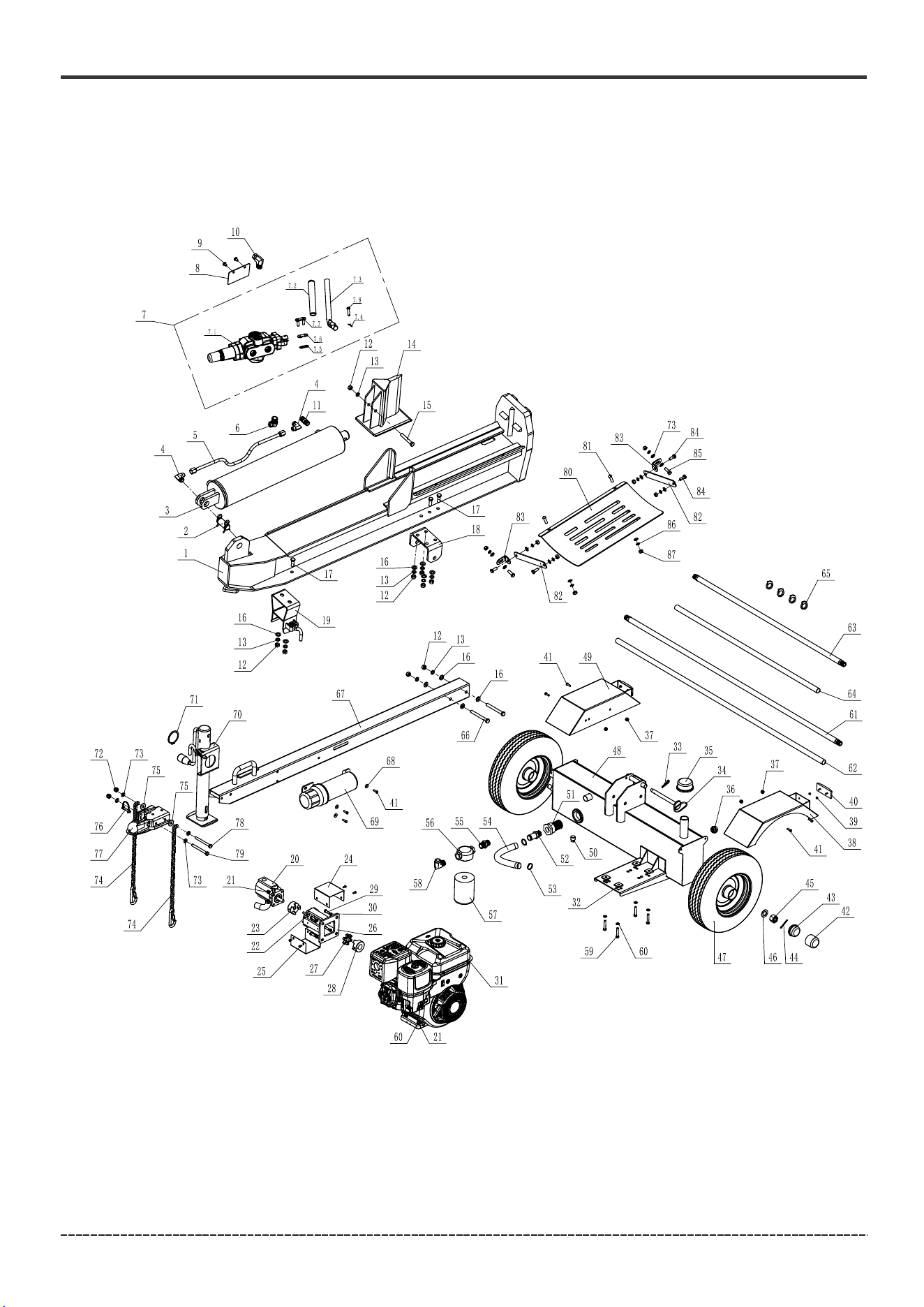
PARTS DIAGRAM AND PART LIST
GS3701 PARTS DIAGRAM
32
English Customer Service: 1-844-FIRMAN1
Parts Diagrams - Parts Lists

33
GS3701 LOG SPLITTER
English Customer Service: 1-844-FIRMAN1
Parts Diagrams - Parts Lists
NO.
Part Number
Description
Qty.
1
2
3
4
5
6
7
7.1
7.2
7.3
7.4
7.5
7.6
7.7
7.8
8
9
10
11
12
13
14
15
16
17
18
19
20
21
22
23
24
25
26
27
28
29
30
31
32
33
34
35
36
37
38
39
40
41
42
43
44
45
710717160
710417020
710417021
710717091
710717092
710717093
710417012
710717171
710717172
710717173
710717174
710717175
710717176
710717177
710717178
710717094
710717095
710717096
710717097
710717098
710717099
710717161
710717101
710717007
710717103
710717104
710717105
710417022
710717044
710717039
710717106
710717107
710717108
710717164
710717110
710717165
710717112
710717048
710467001
710727020
710717113
710717114
710717115
710417014
710717116
710717117
710717118
710727021
710717119
710717120
710717121
710717122
710717123
Beam
Wedge Pin
Hydraulic Cylinder
Right Angle Joiner
Connector
Control Valve
Valve Body
Handle Sleeve
Curved Handle
Pin
Snap
Connecting Plate
Cylindrical Pin
Plate
Bolt M8*12
Connector
Through Joiner2
Nut M12
Lock Washer φ12
Wedge Slide
Bolt M12*75
Washer φ12
Bolt M12*35
Connecting Plate
Locking Device
Gear Pump
Lock Nut M8
Bolt M8*30
Gear Pump Connector
Connector Cover
Screw M5*12
Connector Stand
Elastomer
Engine Connector
Bolt 5/16-24UNF*1
Lock Washer φ8
Engine
Base Mounting
R Pin
Hinge Pin
Oil Plug
Oil Mirror M27*1.5
Lock Nut M6
Fender(right)
Nut M5
Reflector
Bolt M6*20
Cap Tool
Axle Cap
Cotter Pin
Castle Nut 3/4 in.-16
1
1
1
2
1
1
1
1
1
1
1
1
1
1
1
1
2
1
1
9
9
1
1
10
6
1
1
1
8
4
1
2
4
1
1
1
4
4
1
4
1
1
1
1
4
1
4
2
7
1
2
2
2
NO.
Part Number
Description
Qty.
46
47
48
49
50
51
52
53
54
55
56
57
58
59
60
61
62
63
64
65
66
67
68
69
70
71
72
73
74
75
76
77
78
79
80
81
82
83
84
85
86
87
Washer 3/4 in.
Wheel
Hydraulic Oil Tank
Fender(left)
Tank Drain Plug
Internal Oil Filter
Connector
Clamp 15/16 in. - 1-1/4in.
Oil Inlet Hose
Filter Base Assembly
Oil Return Filter
Bolt M8*45
Washer φ8
Clamp
Bolt M12*110
Tow Bar
Washer φ6
Manual Canister
Support Leg
Retaing Ring
Lock Nut M10
Washer φ10
Safety Chain with Hook
Washer φ10
Detent Pin 8*45
2-in. Ball Coupler
Bolt M10*120
Bolt M10*100
Log Catcher
Screw M10*30
Support Arm
Connect Arm
Bolt M10*25
Bolt M10*30
Lock Washer φ10
Nut M10
710717124
710727022
710417023
710717125
710717126
710717127
710717128
710717129
710727023
710717130
710417016
710427005
710717131
710717132
710717045
710727024
710727027
710727025
710727028
710727029
710717133
710717134
710717068
710727026
710417017
710717065
710717075
710717003
710717137
710717138
710717139
710717140
710717141
710717142
710717166
710717167
710717168
710717169
710717021
710717170
710717002
710717027
2
2
1
1
1
1
1
2
1
1
1
1
1
4
8
1
1
1
1
4
2
1
3
1
1
1
2
14
2
2
1
1
1
1
1
2
2
2
4
2
8
8
Hydraulic Hose(Valve-Cylinder)
Connecting Buckle Component
Connector 3/4 NPT - 3/4 NPT
Connector 3/4 NPT - 1/2 NPT
Hydraulic Hose Sheath(Pump-Valve)
Hydraulic Hose(Pump-Valve)
Hydraulic Hose Sheath(Valve-Tank)
Hydraulic Hose(Valve-Tank)

34
English Customer Service: 1-844-FIRMAN1
Service – Warranty
FIRMAN 2 Years Limited Warranty
Engine Warranty
Contact the FIRMAN Service Center and FIRMAN will troubleshoot any log splitter issue via phone
or e-mail. If the problem is not corrected by this method, FIRMAN will, at its option, authorize
evaluation, repair or replacement of the defective part or component at a FIRMAN Service Center.
Service – Warranty
For Engine service and parts information contact Kohler Co. at 1-920-457-4441 or by visiting
www.KohlerEngines.com.
For Log Splitter service and parts information contact FIRMAN at 1-844-347-6261 or at
www.firmanpowerequipment.com.
Even quality-built equipment such as this log splitter may need occasional replacement parts to
maintain it in good condition over the years. To order replacement parts, please provide the following:
Log splitter Model No. Rev. Level and Serial No. found on the Data Decal
Part number or numbers as shown in the Operator’s manual Parts List section.
A brief description of the trouble with the log splitter.
Register your log splitter using the QR code provided or at www.firmanpowerequipment.com.
FIRMAN will also register the warranty upon receipt of your Warranty Registration Card and a
copy of your sales receipt from one of FIRMAN’s retail locations as proof of purchase. Please
submit your warranty registration and your proof of purchase within ten (10) days of the date of
purchase.
Register your log splitter engine as outlined in the Engine Warranty card and on KohlerEngines.com.
The engine is warranted by the engine manufacturer only.
Log Splitter Repair / Replacement Warranty
FIRMAN warrants to the original purchaser that the log splitter components will be free of defects in
material and workmanship for a period of one (1) year (parts and labor) and 2 years (parts and technical
support) from the original date of purchase 90 days (parts and labor) and 180 days (parts) for commercial
& Industrial use. Transportation charges on product submitted for repair or replacement under this
warranty are the sole responsibility of the purchaser. This warranty only applies to the original
purchaser and is not transferable.
Kohler Co. Warrants to the original retail consumer that each new engine will be free from manufacturing
defects in materials or workmanship for the applicable coverage period beginning on date of purchase;
provided the engine is operated and maintained in accordance with Kohler Co.’s instructions and manuals.
Type of use- residential 3 years, commercial/Rental 3 years. For complete warranty information visit
www.KohlerEngines.com or contact Kohler at 1-800-544-2444 (U.S.A. and Canada).
Do Not Return the Unit to the Place of Purchase

35
English Customer Service: 1-844-FIRMAN1
Service – Warranty
Limits of Implied Warranty and Consequential Damage
FIRMAN disclaims any obligation to cover any loss of time, use of this product, freight, or any
incidental or consequential claim by anyone from using this product. THIS WARRANTY IS IN
LIEU OF ALL OTHER WARRANTIES, EXPRESS OR IMPLIED, INCLUDING WARRANTIES OF
MERCHANTABLILITY OR FITNESS FOR A PARTICULAR PURPOSE.
A unit provided as an exchange will be subject to the warranty of the original unit. The length of
the warranty governing the exchanged unit will remain calculated by reference to the purchase
date of the original unit.
The log splitter and engine warranties give you certain legal rights which may change from state to
state. Your state may also have other rights you may be entitled to that are not listed within this
warranty.
Contact Information
You may contact FIRMAN at:
Address
Firman Power Equipment Inc.
Attn: Customer Service
8644 W. Ludlow Dr.
Peoria, AZ 85381
www.firmanpowerequipment.com
We are FIRMAN POWER - And we are here for you.
Installation, Use and Maintenance
This warranty will not apply to parts and/or labor if your product is deemed to have been misused,
neglected, involved in an accident, abused, modified, installed improperly or connected incorrectly.
Normal maintenance is not covered by this warranty.
Other Exclusions
The log splitter and engine warranties exclude:
– Cosmetic defects such as paint, decals, etc.
– Wear items such as filter elements, seals, tires, etc.
– Failures due to acts of God and other force majeure events beyond the manufacturer’s control.
– Problems caused by parts that are not original FIRMAN parts.
Normal Wear
Your product needs periodic parts and service to perform well. This warranty does not cover
repair when normal use has exhausted the life of a part or the equipment as a whole.
Warranty Exclusions
This warranty does not cover the following repairs and equipment.
FIRMAN will provide you with a case number for warranty service. Please keep it for future reference.
Repairs or replacements without prior authorization, or at an unauthorized repair facility, will
not be covered by log splitter or engine warranty.

P/N:710745452 Rev:00
All rights reserved. Any reprinting or unauthorized use
without the written permission is expressly prohibited.
TM
FIRMAN POWER EQUIPMENT
8644 W. LUDLOW DR.
PEORIA, AZ 85381
1-844-347-6261
WWW.FIRMANPOWEREQUIPMENT.COM
