

ABG5520
Original instructions

85º-90º
1
2
3
Fig. 1
Fig. 2 Fig. 3
1
3
2
4
5
7
7
8
10
9
6
1
12
13
14
15
11
1
2
Fig. 4
1
2
3
85º-90º
Fig. 5
Important!
It is essential that you read the instructions in this manual before
operating this machine.
Subject to technical modifications.
1
85º-90º
1
2
3
Fig. 1
Fig. 2 Fig. 3
1
3
2
4
5
7
7
8
10
9
6
1
12
13
14
15
11
1
2
Fig. 4
1
2
3
85º-90º
Fig. 5
2
1
2
Workbench
1.6 mm - 2 mm
> 2 mm
23
3
8
19
22
20
21
x 2
x 2
x 4
M5
M5
D11 x D5
x 1.6mm
1.6 mm - 2 mm
> 2 mm
Fig. 7
Fig. 9
Fig. 11 Fig. 12
Fig. 10
18
17
16
Fig. 8
Fig. 6

3
1
2
Workbench
1.6 mm - 2 mm
> 2 mm
23
3
8
19
22
20
21
x 2
x 2
x 4
M5
M5
D11 x D5
x 1.6mm
1.6 mm - 2 mm
> 2 mm
Fig. 7
Fig. 9
Fig. 11 Fig. 12
Fig. 10
18
17
16
Fig. 8
Fig. 6
GenerAl Power Tool SAFeTY wArnInGS
wArnInG!
read all safety warnings, instructions, illustrations and
specifications provided with this power tool. Failure to follow
all instructions listed below may result in electric shock, fire and/
or serious injury.
Save all warnings and instructions for future reference.
The term “power tool” in the warnings refers to your mains-
operated (corded) power tool or battery-operated (cordless)
power tool.
work AreA SAFeTY
keep work area clean and well lit. Cluttered or dark areas
invite accidents.
Do not operate power tools in explosive atmospheres, such
as in the presence of flammable liquids, gases or dust.
Power tools create sparks which may ignite the dust or fumes.
keep children and bystanders away while operating a
power tool. Distractions can cause you to lose control.
elecTrIcAl SAFeTY
Power tool plugs must match the outlet. never modify the
plug in any way. Do not use any adapter plugs with earthed
(grounded) power tools. Unmodified plugs and matching
outlets will reduce risk of electric shock.
Avoid body contact with earthed or grounded surfaces,
such as pipes, radiators, ranges and refrigerators. There is
an increased risk of electric shock if your body is earthed or
grounded.
Do not expose power tools to rain or wet conditions. Water
entering a power tool will increase the risk of electric shock.
Do not abuse the cord. never use the cord for carrying,
pulling or unplugging the power tool. keep cord away
from heat, oil, sharp edges or moving parts. Damaged or
entangled cords increase the risk of electric shock.
when operating a power tool outdoors, use an extension
cord suitable for outdoor use. Use of a cord suitable for
outdoor use reduces the risk of electric shock.
If operating a power tool in a damp location is unavoidable,
use a residual current device (rcD) protected supply. Use of
an RCD reduces the risk of electric shock.
PerSonAl SAFeTY
Stay alert, watch what you are doing and use common
sense when operating a power tool. Do not use a power tool
while you are tired or under the influence of drugs, alcohol
or medication. A moment of inattention while operating power
tools may result in serious personal injury.
Use personal protective equipment. Always wear eye
protection. Protective equipment such as dust mask, non-
skid safety shoes, hard hat or hearing protection used for
appropriate conditions will reduce personal injuries.
Prevent unintentional starting. ensure the switch is in the
o-position before connecting to power source and/or
battery pack, picking up or carrying the tool. Carrying power
tools with your finger on the switch or energising power tools
that have the switch on invites accidents.
remove any adjusting key or wrench before turning the
power tool on. A wrench or a key left attached to a rotating
part of the power tool may result in personal injury.
Do not overreach. keep proper footing and balance at
all times. This enables better control of the power tool in
unexpected situations.
Dress properly. Do not wear loose clothing or jewellery.
keep your hair and clothing away from moving parts. Loose
clothes, jewellery or long hair can be caught in moving parts.
If devices are provided for the connection of dust extraction
and collection facilities, ensure these are connected and
properly used. Use of dust collection can reduce dust-related
hazards.
Do not let familiarity gained from frequent use of tools
allow you to become complacent and ignore tool safety
principles. A careless action can cause severe injury within a
fraction of a second.
Power Tool USe AnD cAre
Do not force the power tool. Use the correct power tool for
your application. The correct power tool will do the job better
and safer at the rate for which it was designed.
Do not use the power tool if the switch does not turn it on
and o. Any power tool that cannot be controlled with the
switch is dangerous and must be repaired.
Disconnect the plug from the power source and/or remove
the battery pack, if detachable, from the power tool before
making any adjustments, changing accessories, or storing
power tools. Such preventive safety measures reduce the risk
of starting the power tool accidentally.
Store idle power tools out of the reach of children and do
not allow persons unfamiliar with the power tool or these
instructions to operate the power tool. Power tools are
dangerous in the hands of untrained users.
Maintain power tools and accessories. check for
misalignment or binding of moving parts, breakage of parts
and any other condition that may aect the power tool’s
operation. If damaged, have the power tool repaired before
use. Many accidents are caused by poorly maintained power
tools.
keep cutting tools sharp and clean. Properly maintained
cutting tools with sharp cutting edges are less likely to bind and
are easier to control.
Use the power tool, accessories and tool bits etc. in
accordance with these instructions, taking into account
the working conditions and the work to be performed. Use
of the power tool for operations dierent from those intended
could result in a hazardous situation.
keep handles and grasping surfaces dry, clean and free
from oil and grease. Slippery handles and grasping surfaces
do not allow for safe handling and control of the tool in
unexpected situations.
ServIce
Have your power tool serviced by a qualified repair person
using only identical replacement parts. This will ensure that
the safety of the power tool is maintained.
BencH GrInDer SAFeTY wArnInGS
■ Do not use a damaged accessory. Before each use,
inspect the accessory such as abrasive wheels for chips
and cracks. After inspecting and installing an accessory,
position yourself and bystanders away from the plane
of the rotating accessory and run the power tool at
maximum no-load speed for one minute. Damaged
accessories will normally break apart during this test time.
■ The rated speed of the accessory must be at least equal
to the maximum speed marked on the power tool.

4
Accessories running faster than their rated speed can break
and fly apart.
■ never grind on the sides of a grinding wheel. Grinding
on the side can cause the wheel to break and fly apart.
ADDITIonAl SAFeTY wArnInGS
■ Always wear safety goggles and a dust mask.
■ Wear ear protectors. Exposure to noise can cause hearing
loss.
■ The product is not suitable for wet grinding.
■ Always use the product with accessories on both spindles
in order to limit the risk of contact with the rotating spindle.
■ Always use the guard, work rest, transparent screen and
spark arrestor as required for the accessory.
■ Replace damaged or deeply grooved wheels.
■ Always adjust the work rest so that the angle between
the work rest and the tangent of the accessory is always
greater than 85°.
■ Mount the bench grinder firmly to the workbench, grinding
stand or other rigid frame before operation. An unsecured
bench grinder is unstable and may move during operation.
This may result in damage or injury.
■ Provide adequate general or localised lighting to prevent
stroboscopic effect and hazards.
■ Prior to operation, inspect the components and any
accessories of the bench grinder to ensure there are no
conditions that may affect proper operation. Tighten
grinding wheel lock nuts, securing bolts and all clamps and
guards.
■ Prior to each start up, inspect the grinding wheel for
damage. Do not use damaged or unshaped wheels. Replace
any damaged grinding wheel according to the instructions.
■ Check that the wheel rotates freely prior to each start up.
With the bench grinder unplugged and the switch turned
to OFF, carefully spin the wheel by hand. The wheel should
not contact any components of the bench grinder, and
there should be no binding or other conditions that may
affect proper operation.
■ During each start-up, stand to one side of the grinder and
switch it ON. Let the grinder operate at full speed for one
minute so that any undetected flaws or cracks of the wheel
will become apparent. Do not contact the wheel with the
work piece until the bench grinder has reached full speed.
■ Do not force the product. Use the correct product for your
application. The correct product will do the job better and
safer at the rate for which it was designed.
■ Always hold the workpiece firmly when grinding.
■ To minimise the risk of tipping the product, always support
long workpieces.
■ Never grind more than one workpiece at a time. Do not
stack more than one workpiece on the work rest at a time.
■ Do not reach into the product while it is running.
■ Avoid awkward operations and hand positions where
a sudden slip could cause your hand to move into the
grinding wheel.
■ Avoid kickback by grinding in accordance with directional
arrows.
■ Never stand or have any part of your body in line with the
path of the workpiece.
■ Chips and splinters must not be removed while the product
is running.
■ Keep hands and body parts clear of grinding wheels.
Contacting the rotating wheel may cause injury.
■ Always use guards and transparent screens. Keep all
guards in place and in working order. Operating the bench
grinder without guards or with damaged guards may result
in injury.
■ Avoid burns. Grinding may cause items and the grinding
wheel to become hot. Do not touch the grinding wheel or
items that may be hot.
■ Do not use the grinder to work on small items or items
which cannot be held properly. The item may be thrown
and result in injury.
■ Never grind on the side of the wheel. The wheel will shatter.
Grind on the face of the wheel only.
■ Never leave a running tool unattended. Turn the power
switch to OFF. The grinding wheels continue to rotate after
the tool is switched off. Do not leave the tool until it has
come to a complete stop.
■ Never reach behind or beneath the grinding wheels.
■ Use ear protection, such as plugs or muffs, during extended
periods of operation.
■ Remove the plug before carrying out any adjustment,
servicing or maintenance. The power cord must remain
unplugged whenever you are maintaining your bench
grinder.
■ Adjust the work rests and spark arrestors frequently so as
to compensate for wear of the grinding wheel.
■ Adjust the work rests whenever necessary to keep the
distance between the work rests and the grinding wheels as
small as possible. This distance should be less than or equal
to 2 mm. As the diameter of the grinding wheel decreases
with use, maintain the maximum work rest distance by
adjusting it.
■ Adjust spark arrestors whenever necessary to keep the
distance between the spark arrestors and the grinding
wheels as small as possible. This distance should be less
than or equal to 2 mm. As the diameter of the grinding
wheel decreases with use, maintain the maximum spark
arrestor distance by adjusting it.
■ Replace the worn wheel when the distance of 2 mm
between the spark arrestor/work rest and the wheel are no
longer able to be maintained.
■ If the work rest becomes worn or damaged, replace it
with an identical replacement from the authorised service
centre.
■ When fitting a new grinding wheel, always check that the
stated maximum RPM meets or exceeds that stated on the
grinder. Ensure the wheel diameter and arbor size meet
that stated on the specifications. Also check the new wheel
for damage, such as flaws or cracks.
■ If the supply cord is damaged, it must be replaced by an
authorised service centre in order to avoid a safety hazard.
■ It is recommended that the product always be supplied via
a residual current device having a rated residual current of
30mA or less.
5
GrInDInG wHeel SAFeTY InSTrUcTIonS
wArnInG
To reduce the risk of injury, user must read and comply with
instructions, warnings and operator’s manual before starting
to use this grinding wheel. Failure to heed these warnings
can result in wheel breakage and serious personal injury.
Save these instructions.
■ The use of any wheel other than the one recommended
in the machine instruction manual may present a risk
of personal injury. Use only grinding wheels which have
marked speed equal or greater to that marked on the
machine.
■ Never use grinding wheel that is too thick to allow outer
flange to engage with the flats on the spindle. Larger
wheels will come in contact with the wheel guards, while
thicker wheels will prevent the bolt from securing the wheel
on the spindle. Either of these situations could result in a
serious accident and can cause serious personal injury.
■ This wheel is for grinding and shaping metal. Do not
attempt to do cut-off operation.
■ This grinding wheel is only suitable for dry grinding.
■ Do not use damaged grinding wheels, do not use wheels
that are chipped, cracked or otherwise defective.
■ Ensure that the abrasive grinding wheel is correctly fitted
and tightened before use.
■ Machine should never be connected to power supply when
you are installing or removing grinding wheels.
■ Store your spare grinding wheel carefully.
● Keep the wheel inside the original package if possible.
● Store the wheel in a dry area at room temperature.
● Wheels may be stored vertically on a shelf.
● Do not allow the wheels to fall or suffer any impact.
Information available on the grinding wheel label
The information on the wheel label is important. Read and
check it carefully to ensure you are selecting the correct type
of wheel.
1. Manufacturer, supplier, importer or trade mark.
2. Nominal dimensions of grinding wheel, in particular the
diameter of the bore.
3. Abrasive type, grain size, grade or hardness, type of bond
and use of reinforcement.
4. Maximum operation speed in metres per second.
5. Maximum permissible speed of rotation in 1/min .
6. For declaration of conformity, the abrasive products shall be
marked with EN 12413.
7. Restriction of use and safety warning symbols.
8. Traceability code, eg. A production/batch number, expiry
date or series number.
InTenDeD USe
■ This bench grinder is intended for grinding and shaping
metal. It can be used to sharpen metal hand tools (e.g.
chisels, axes, knives) or drill bits, remove burrs or sharp
edges.
■ Never use the bench grinder for cut-off operations.
reSIDUAl rISk
Even when the machine is used as prescribed, it is still
impossible to completely eliminate certain residual risk factors.
The following hazards may arise in use and the operator should
pay special attention to avoid the following:
■ Risk of contact with unguarded parts of the rotating wheel.
■ Burn hazard from contact with hot wheel or work piece.
■ Damage to respiratory system if effective dust mask is not
worn.
■ Damage to hearing if effective hearing protection is not
worn.
envIronMenTAl ProTecTIon
Recycle raw materials instead of disposing of as
waste. The machine, accessories and packaging
should be sorted for environmental-friendly
recycling.
SYMBolS
Safety alert
V
Volts
Hz
Hertz
Alternating current
W
Watts
n
0
No-load speed
min
-1
Revolutions or reciprocations per minute
Regulatory Compliance Mark (RCM). This product
meets applicable regulatory requirements.
Please read the instructions carefully before
starting the machine.
Wear ear protection
Wear eye protection
Not for wet grinding or cutting
6
Replacement parts
Wheel (36 grit) 089056004006
Wheel (60 grit) 089056004055
Left work rest 089056004028
Right work rest 089056004053
Light bulb 089056004066
Transparent screen
assembly (left)
089056004022
Transparent screen
assembly (right)
089056006005
wArnInG!
The declared noise emission value(s) have been measured in
accordance with a standard test method of EN 62841-1 and
EN 62841-3-4, and may be used for comparing one tool with
another. The declared noise emission value(s) may also be used
in a preliminary assessment of exposure.
The noise emissions during actual use of the power tool can
dier from the declared values depending on the ways in which
the tool is used especially what kind of workpiece is processed.
Identify safety measures to protect the operator that are based
on an estimation of exposure in the actual conditions of use
(taking account of all parts of the operating cycle such as the
times when the tool is switched o and when it is running idle in
addition to the trigger time).
Wear ear protectors. Exposure to noise can cause hearing loss.
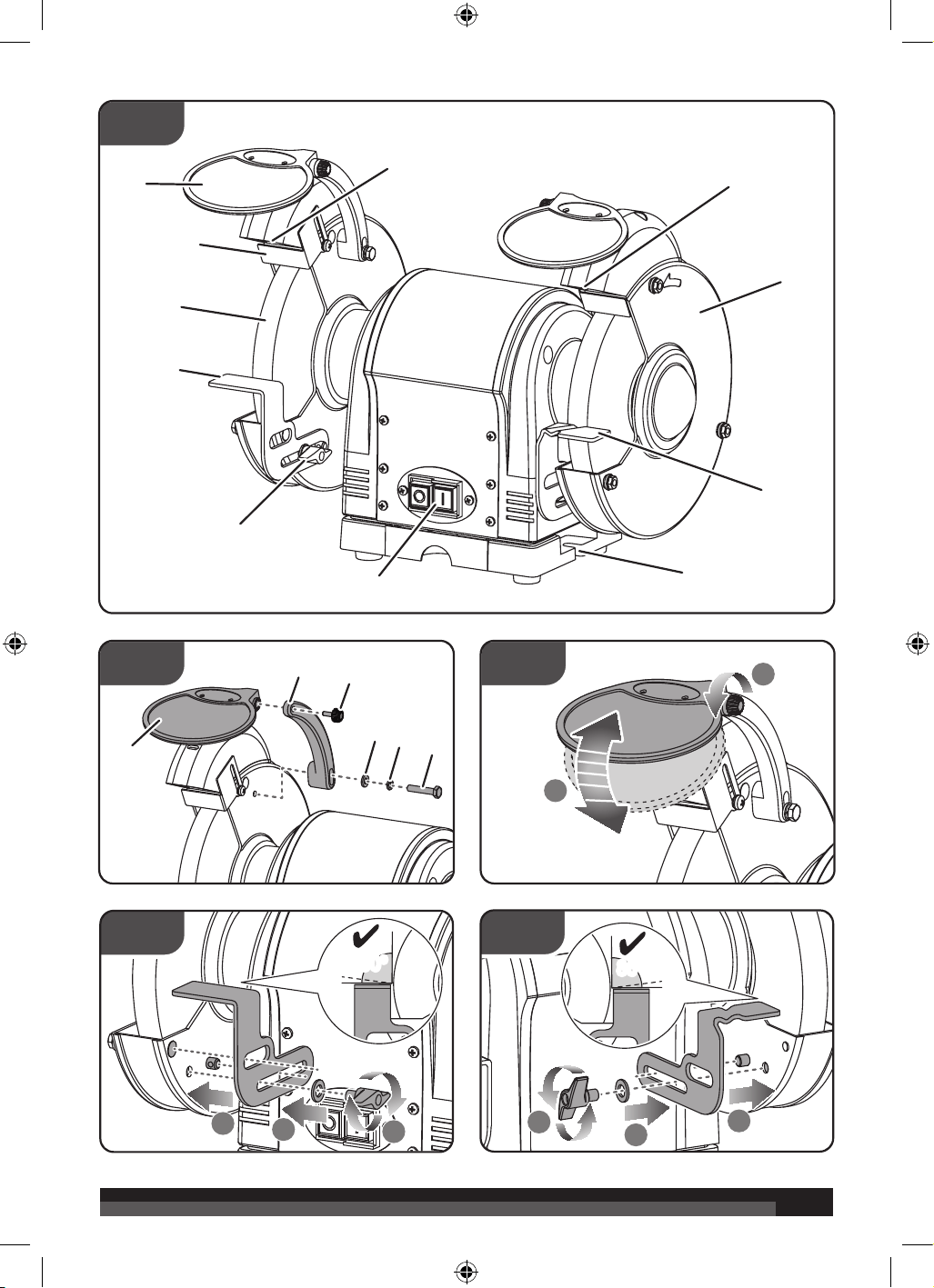
DeScrIPTIon
1. Transparent screen x 2
2. Spark arrestor x 2
3. Grinding wheel x 2
4. Work rest (left)
5. Work rest lock knob x 2
6. On/Off switch
7. Lamp
8. Wheel guard cover x 2
9. Work rest (right)
10. Base – bolt-down area
11. Transparent screen mounting rod
12. Transparent screen fixing knob
13. Flat washer
14. Spring washer
15. Hex bolt
16. Mounting hex bolt (not supplied)
17. Mounting flat washer (not supplied)
18. Mounting nut (not supplied)
19. Flat washer
20. Wheel nut
21. Outer flange
22. Hex flange nut
23. Coolant tray
know YoUr GrInDer
See figure 1.
The safe use of this product requires an understanding of
Do not use chipped, cracked or defective grinding
wheel
Wear safety gloves.
Wheel rotation direction (shown on wheel label)
Wheel rotation direction (shown on wheel guard)
Visible radiation, instructional safeguard
Waste electrical products should not be disposed
of with household waste. Please recycle where
facilities exist. Check with your Local Authority or
retailer for recycling advice.
ProDUcT SPecIFIcATIonS
Motor type Induction
Horsepower 3/4 HP, 550W
Motor ratings 230 - 240 V ~ 50 Hz
No-load speed 3000 min
-1
Wheel diameter 8" (200 mm)
Wheel width 1" (25.4 mm)
Arbor hole 5/8" (15.88 mm)
Abrasive wheels
supplied
Coarse (36 grit) left wheel
Fine (60 grit) right wheel
Lamp power (type) 12V.10W (Incandescent)
Net weight 17.6 kg
Minimum workpiece
dimensions
2 mm x 2 mm x 30 mm
Measured sound values determined according to EN 62841:
A-weighted sound
pressure level
81.0 dB (A)
Uncertainty K 3 dB (A)
A-weighted sound
power level
87.0 dB (A)
Uncertainty K 3 dB (A)
Wear ear protectors.
7
the information on the tool and in this operator’s manual
as well as a knowledge of the project you are attempting.
Before use of this product, familiarize yourself with all
operating features and safety rules.
ASSeMBlY
UNPACKING
■ Carefully remove the tool and any accessories from the
box. Make sure that all items listed in the packing list are
included.
■ Inspect the tool carefully to make sure no breakage or
damage occurred during shipping.
■ Do not discard the packing material until you have carefully
inspected and satisfactorily operated the tool.
PAckInG lIST
Work rest (left/right) 2
Transparent screen 2
Transparent screen fixing knob 2
Transparent screen mounting rod (left/
right)
2
Transparent screen assembly mounting
bolt
2
Transparent screen assembly mounting
washer
2
Transparent screen assembly mounting
locking washer
2
Hex nut 4
Washer 4
wArnInG
If any parts are damaged or missing do not operate this
product until the parts are replaced. Use of this product with
damaged or missing parts could result in serious personal
injury.
wArnInG
Do not attempt to modify this tool or create accessories not
recommended for use with this tool. Any such alteration
or modification is misuse and could result in a hazardous
condition leading to possible serious personal injury.
InSTAllInG AnD ADjUSTInG TrAnSPArenT ScreenS
See figures 2 - 3.
Transparent screens must be installed before operating the
grinder.
1. Using hex bolts, mount the transparent screen mounting
rods to the inner left and right side of the wheel guard
covers.
2. Slide the transparent screens into the mounting rods.
3. Tighten the transparent screen fixing knobs, but leave
them loose enough to allow the transparent screens to be
raised and lowered easily.
InSTAllInG AnD ADjUSTInG work reSTS
See figure 4- 6.
1. Attach the left work rest to the left wheel guard. Make sure
the pin on the wheel guard sits in the lower slot of the work
rest.
2. Slide the work rest in or out to adjust the distance gap.
noTe: The distance between the work rest and wheel
must be between 1.6 mm and 2 mm.
3. Lcok the work rest in place with a flat washer and lock knob.
4. Repeat the steps above to install the right work rest on the
other side.
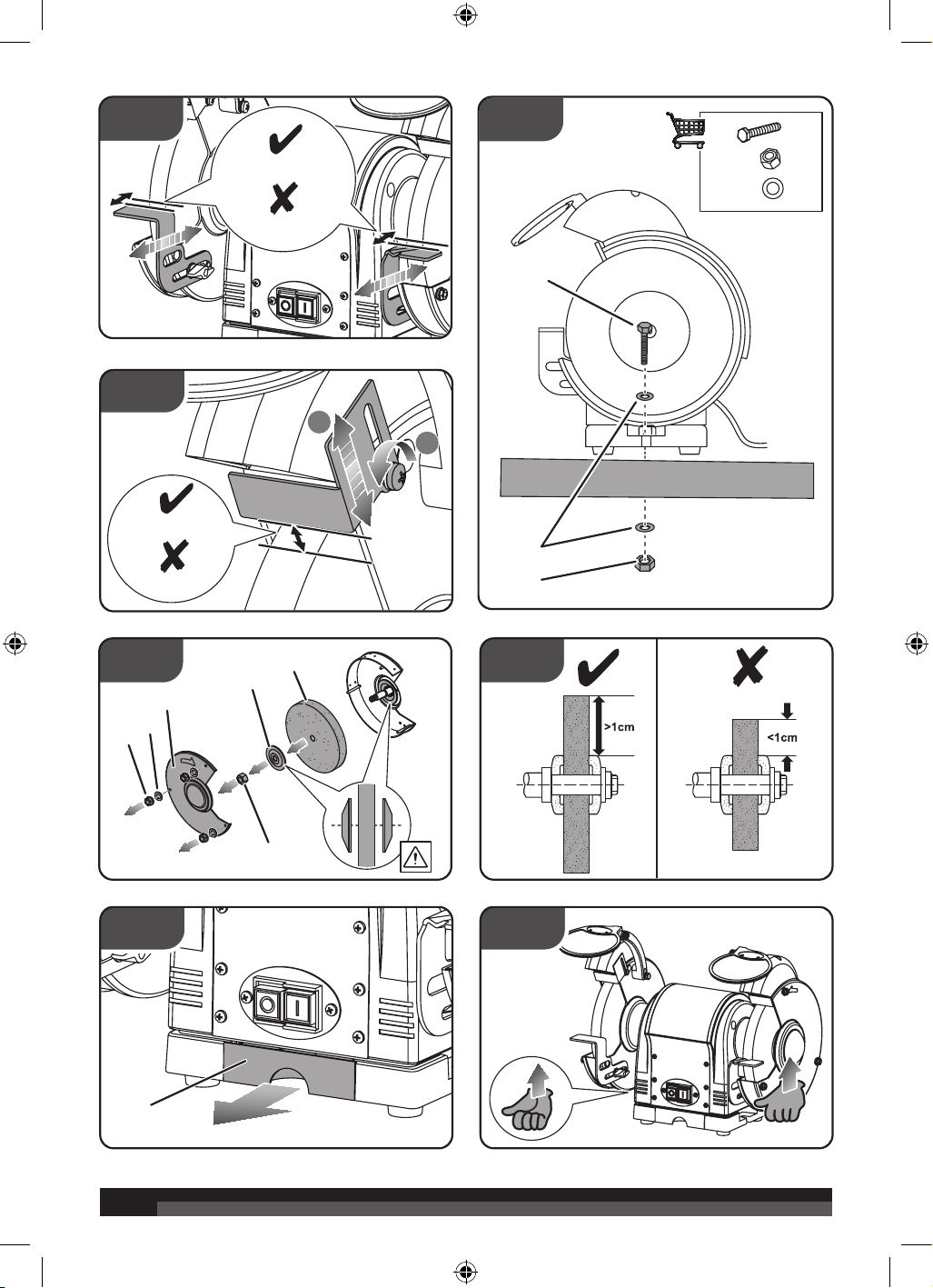
ADjUSTInG SPArk ArreSTorS
See figure 7.
1. Loosen the spark arrestor locking screw.
2. Adjust the spark arrestor so that the distance to the
grinding wheel is between 1.6 mm and 2 mm.
MoUnTInG THe GrInDer
See figure 8.
Before using the grinder, it must be properly and securely
mounted on a sturdy workbench or grinding stand.
1. Position the grinder on the workbench.
2. Mark on the workbench through the two mounting holes
located at the grinder base.
3. Drill holes on the marks of the workbench.
4. Using two M5 bolts, washers, lock-washers and nuts (not
supplied), secure the grinder to the workbench.
wArnInG
Bench grinders vibrate. Grinder movement during high-
speed rotation may cause damage or injury to the workpiece
or operator.
oPerATIon
wArnInG
Do not allow familiarity with tools to make you careless.
Remember that a careless fraction of a second is suicient
to inflict severe injury.
wArnInG
Always wear safety goggles or safety glasses with side
shields when operating tools. Failure to do so could result
in objects being thrown into your eyes resulting in possible
serious injury.
wArnInG
Disconnect the tool before leaving the work area, moving
the tool to another location, or handing the tool to another
person. Failure to do so could result in serious personal
injury.
8
SwITcHInG on/oFF
See figure 1.
Push the On/O switch to turn the grinder on or o.
GrInDInG
■ Adjust the work rest to accommodate large or unusually-
shaped workpieces.
■ Always keep the workpiece moving across the face of the
grinding wheel. Grinding continuously on the same spot of
the wheel will cause grooves to be worn into the wheel. The
wheel may be easily cracked or damaged, and grinding of
other objects will be difficult.
■ If the workpiece becomes hot, dip it into the water or oil.
■ Always grind on the face of the wheel (around the
diameter), NEVER on the sides. Side pressure on grinding
wheels can cause cracking and damage.
■ Use the left work rest for grinding general workpieces. Use
the groove on the right work rest for grinding drill bits.
rePlAcInG GrInDInG wHeel
See figure 9 - 10.
These are some reasons the wheel may require to be changed:
■ If the face of the grinding wheel is worn unevenly, becomes
grooved, or is no longer smooth and flat.
■ If the diameter of the grinding wheel is no longer round.
■ If the surface of the wheel becomes loaded and dull with
workpiece material.
■ If there is any sign of damage.
■ If it becomes difficult to work with.
■ If the work rest / spark arrestor cannot be adjusted to max
2 mm distance from surface.
■ Replace grinding wheel when its diameter wear value is
more than 8 mm.
■ if ≤ 1 cm of disc protrudes from flange. See figure 10.
wArnInG
Turn the power o and remove the plug before changing
the grinding wheels.
1. Use a wrench to remove the hex flange nut, then remove
the wheel guard cover.
2. Fit an appropriately-sized wrench on the spindle hex nut.
3. Loosen the wheel nut in a clockwise direction for the left
side and a counter-clockwise direction for the right side.
4. Remove the outer flange and grinding wheel. To remove
the hex nut, turn the wrench and nut until the wrench is
resting on the workbench behind the tool.
5. Inspect the new wheel carefully to ensure there are no
cracks, chips or other damage. Use the ring method to test
for cracks. If the wheel has a crack, it will not ring when it is
tapped with a hard object.
wArnInG
Do not install or use a damaged grinding wheel. The force
of rotation may cause a damaged wheel to fly apart, injuring
operators or bystanders.
6. Wipe the flange surfaces clean, then install the new wheel,
flange and spindle hex nut.
wArnInG
Do not over-tighten the spindle hex nut, because this may
cause the wheel to crack.
7. Ensure the grinding wheel and outer flange are properly
seated on the spindle shaft.
8. Replace the wheel guard cover.
9. Re-position and re-adjust the work rest, spark arrestor and
transparent screens after installation of the new wheel.
wArnInG
When turning the grinder on with a newly-installed wheel,
DO NOT STAND IN FRONT OF THE GRINDER. Stand to
the side and allow the grinder to run for at least one minute
before proceeding to use it.
MAInTenAnce
wArnInG
For greater safety and reliability, all repairs should be
performed by an authorised service centre.
wArnInG
When servicing, use only identical replacement parts. Use
of any other parts may create a hazard or cause product
damage.
wArnInG
Servicing beyond recommended maintenance should only
be performed by an authorized qualified technician.
GENERAL MAINTENANCE
Check power cord Before each use
Check wheels for cracks Before each use
Check moving parts for alignment
and binding issues
Before each use
Replace grinding wheels As needed
Clean and vacuum dust from the
motor housing and other grinder
parts
As needed
Replace work-light bulb As needed
Avoid using solvents when cleaning plastic parts. Most plastics
are susceptible to damage from various types of commercial
solvents and may be damaged by their use. Use clean cloths to
remove dirt, dust, oil, grease, etc.

9
wArnInG
Do not at any time let brake fluids, gasoline, petroleum-
based products, penetrating oils, etc., come in contact with
plastic parts. Chemicals can damage, weaken or destroy
plastic which may result in serious personal injury.
lUBrIcATIon
No lubrication required as bearings are greased for life.
coolAnT TrAY
See figure 11.
When grinding, metal objects become heated quickly. It is
important to keep moving the object back and forth across the
face of the grinding wheel, and to cool the object frequently
using the coolant tray.
rePlAcInG work-lIGHT BUlB
Contact dealer or retailer for replacement bulbs.
1. When the light bulb is worn out and will no longer work,
unfasten the screws that hold the lamp cover, then gently
remove the bulb from the holder by pushing ‘in’ and turning
counter-clockwise.
2. To replace, gently push the new light bulb into the socket
and turn clockwise.
3. Re-attach the lamp cover.
Use only AEG accessories and spare parts. Should components
need to be replaced which have not been described, please
contact one of our AEG service agents (see our list of
guarantee/service addresses).
If needed, an exploded view of the product can be ordered.
Please state the Article No. as well as the machine type printed
on the label and order the drawing at your local service agents
or directly at:
Techtronic Industries Australia Pty ltd
PO Box 1065
Mount Waverley VIC 3149
Tel. no. 1300 234 797
Australia
Techtronic Industries n.Z. limited
PO Box 12-806
Penrose AUCKLAND 1642
Tel no. 0800 234 797
New Zealand
TrAnSPorTATIon AnD STorAGe
See figure 12.
■ When storing the product, disconnect the power cord.
■ Clean the product using a brush and vacuum cleaner.
■ Always carry and lift the product according to the
instruction in this user manual.
■ Protect the product from any heavy impact or strong
vibrations which may occur during transportation in
vehicles.
■ Secure the product to prevent it from slipping or falling
over.
■ Store the product and its accessories in a dry, safe place
which is not accessible to children.
■ We recommend using the original package for storage to
protect the product against dust.

Techtronic Industries Australia Pty Ltd
31 Gilby Road, Mount Waverley
VIC, 3149, Australia
Techtronic Industries N.Z. Limited
Unit C, 70 Business Parade South
Highbrook, Auckland 2013, New Zealand
www.aegpowertools.com.au
www.aegpowertools.co.nz
20200528v4b
AEG is a registered trademark used under
license from AB Electrolux (publ).
© 2016-20 Techtronic Cordless GP.
