

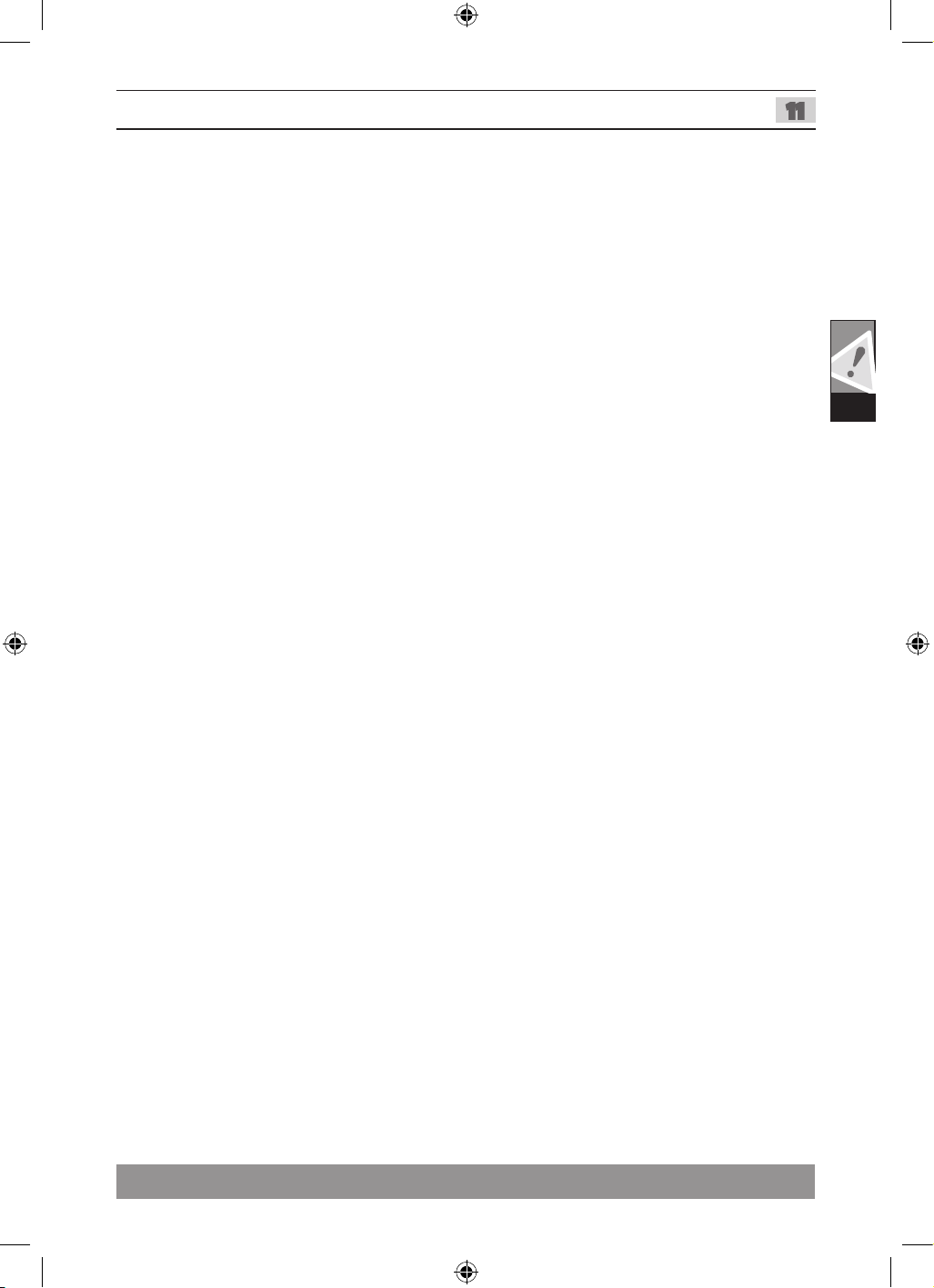
WS 9-100
WS 11-125
Original instructions

Please read and save
these instructions!
Technical Data, Safety Instructions, Specied Conditions of Use,
Mains connection, Maintenance, Symbols
English
1111
Please read and save
these instructions!
Technical Data, Safety Instructions, Specied Conditions of Use,
Mains connection, Maintenance, Symbols
English
1111

TIP
II
VI
IV
VIII
I III
VII
V
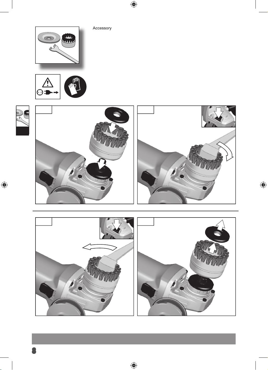
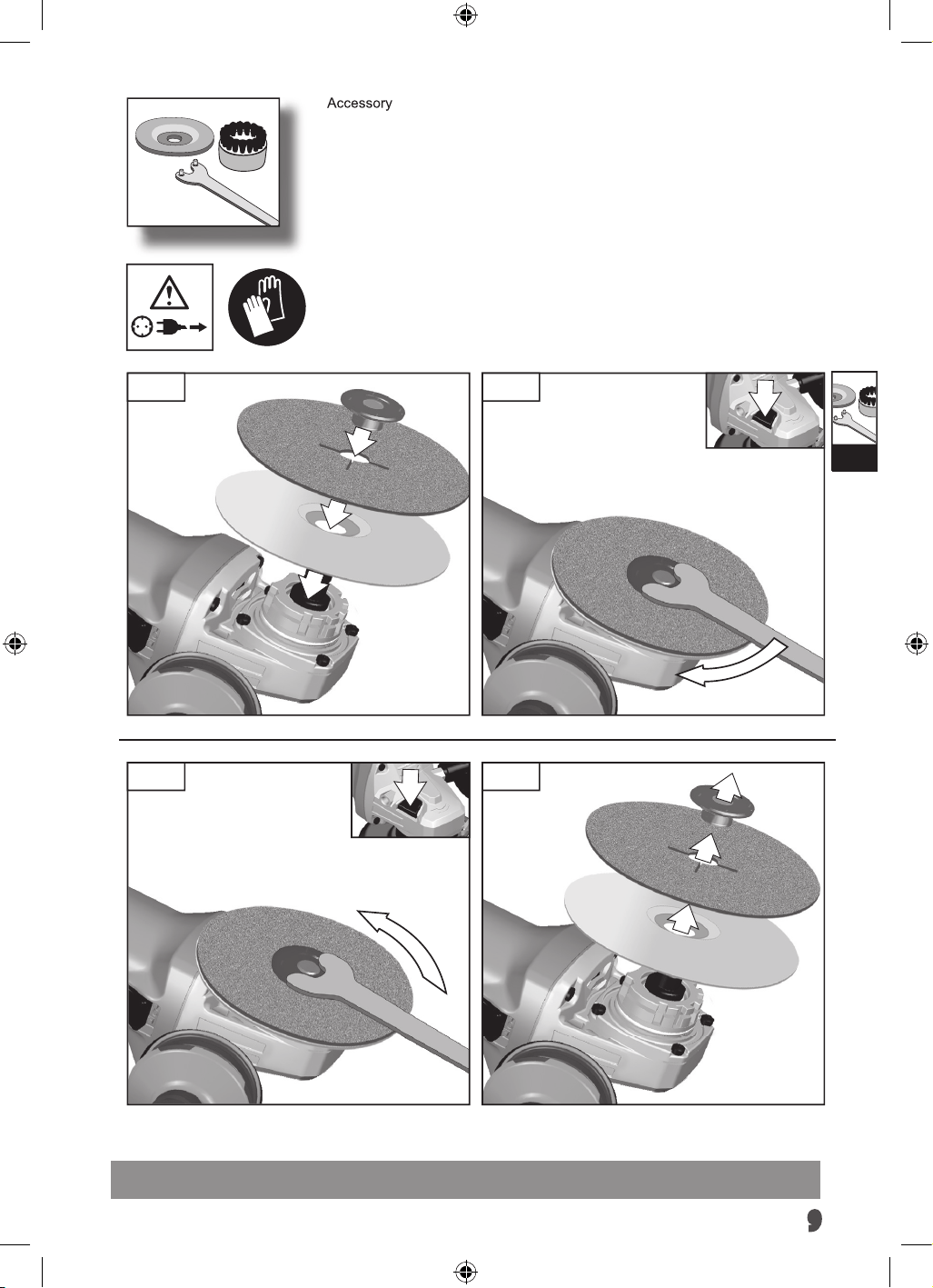
Accessory
425_009_WS9-WS11-WS12_4-2.indd 1 07.11.14 14:48
Important!
It is essential that you read the instructions in this
manual before assembling, operating, and maintaining
the product.
Subject to technical modifications.
TIP
II
VI
IV
VIII
I III
VII
V
Accessory
425_009_WS9-WS11-WS12_4-2.indd 1 07.11.14 14:48
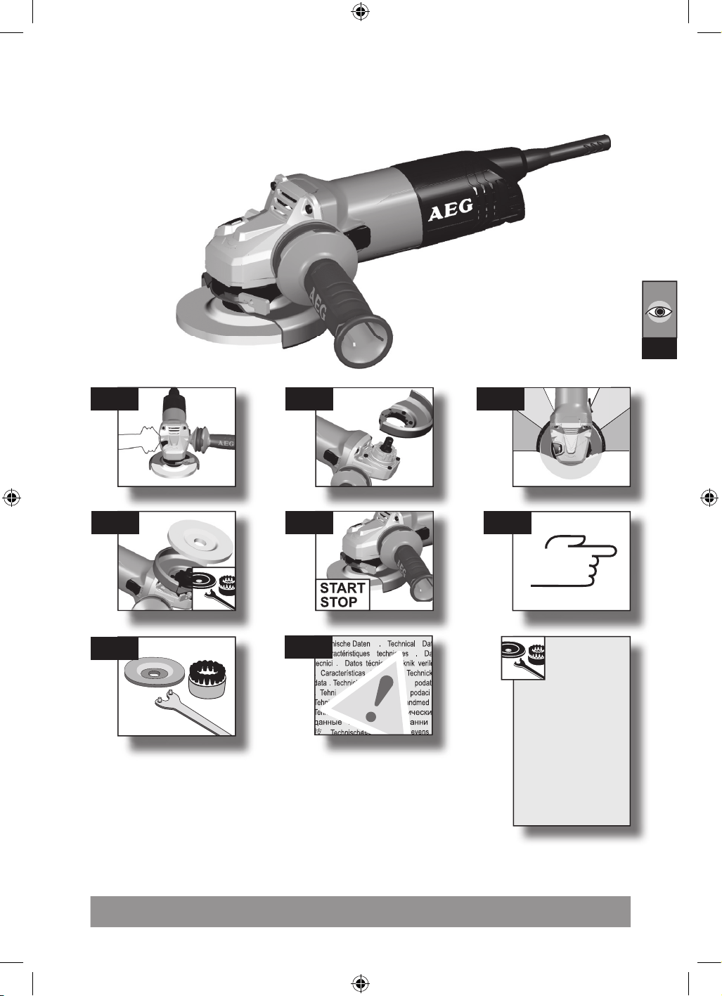
2
I
425_009_WS9-WS11-WS12_4-2.indd 2 07.11.14 14:48
3
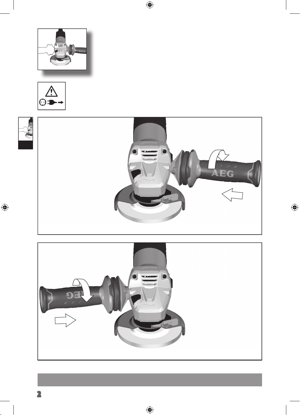
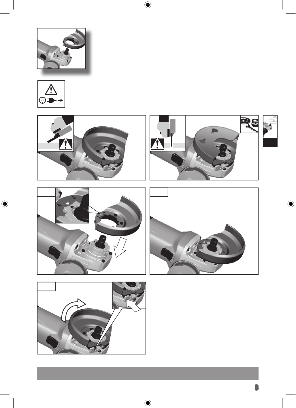
II
1. 2.
1
2
3.
425_009_WS9-WS11-WS12_4-2.indd 3 07.11.14 14:48
2
I
425_009_WS9-WS11-WS12_4-2.indd 2 07.11.14 14:48
3
II
1. 2.
1
2
3.
425_009_WS9-WS11-WS12_4-2.indd 3 07.11.14 14:48
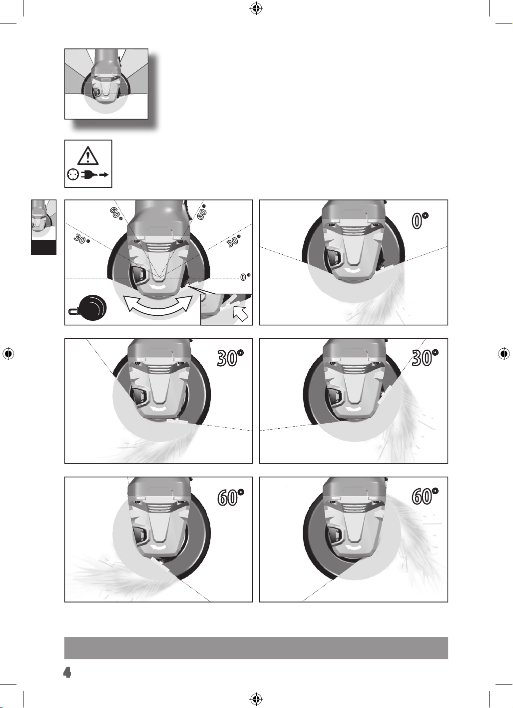
4
III
0°
30°
30°
60°
60°
30
°
60
°
30
°
60
°
0
°
click
1
2
2
425_009_WS9-WS11-WS12_4-2.indd 4 07.11.14 14:48
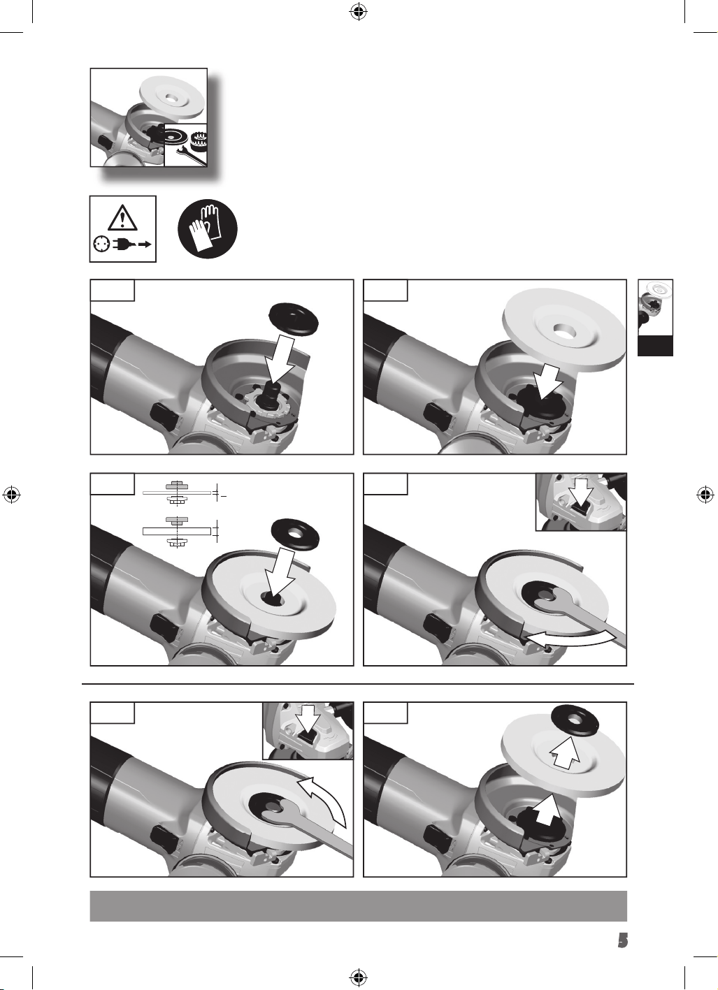
5
IV
< 6 mm
> 6 mm
1. 2.
3. 4.
1. 2.
425_009_WS9-WS11-WS12_4-2.indd 5 07.11.14 14:48
4
III
0°
30°
30°
60°
60°
30
°
60
°
30
°
60
°
0
°
click
1
2
2
425_009_WS9-WS11-WS12_4-2.indd 4 07.11.14 14:48
5
IV
< 6 mm
> 6 mm
1. 2.
3. 4.
1. 2.
425_009_WS9-WS11-WS12_4-2.indd 5 07.11.14 14:48
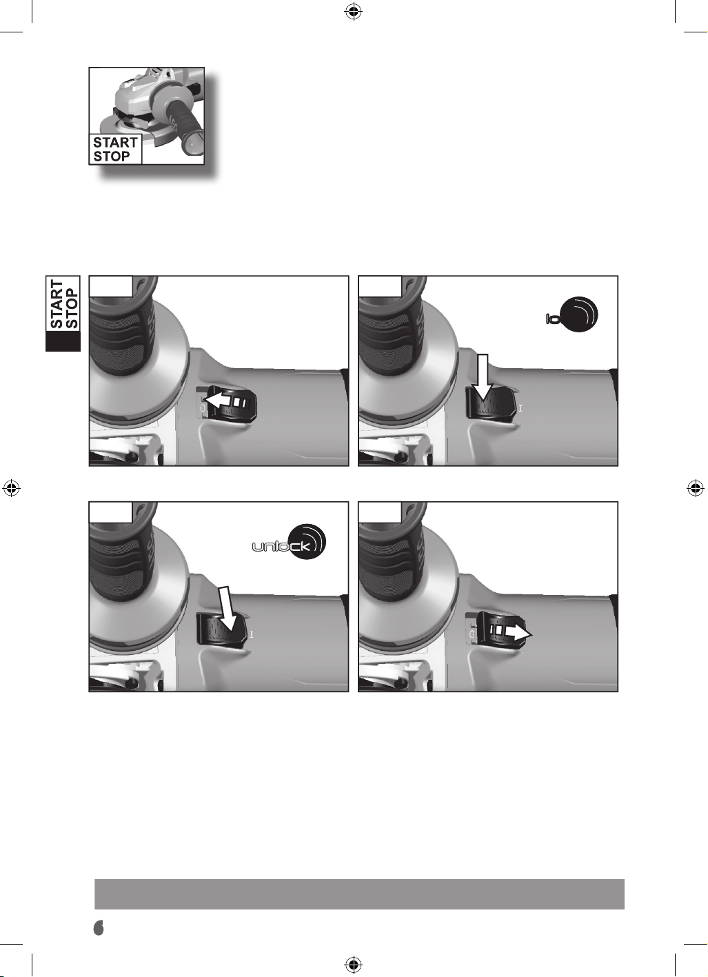
unlock
lock
Start
Stop
unlock
unlock
unlock
unlock
unlock
1. 2.
1. 2.
425_009_WS9-WS11-WS12_4-2.indd 7 07.11.14 14:48
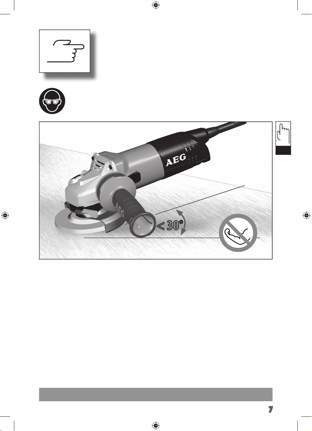
6
V
TIP
< 30°
TIP
VI
TIP
425_009_WS9-WS11-WS12_4-2.indd 9 07.11.14 14:48
7
unlock
lock
Start
Stop
unlock
unlock
unlock
unlock
unlock
1. 2.
1. 2.
425_009_WS9-WS11-WS12_4-2.indd 7 07.11.14 14:48
6
V
TIP
< 30°
TIP
VI
TIP
425_009_WS9-WS11-WS12_4-2.indd 9 07.11.14 14:48
7
88
1. 2.
1. 2.
VII
425_009_WS9-WS11-WS12_4-2.indd 10 07.11.14 14:48
8
VII
1. 2.
1. 2.
425_009_WS9-WS11-WS12_4-2.indd 11 07.11.14 14:48
9
99
1. 2.
1. 2.
VII
425_009_WS9-WS11-WS12_4-2.indd 10 07.11.14 14:48
8
VII
1. 2.
1. 2.
425_009_WS9-WS11-WS12_4-2.indd 11 07.11.14 14:48
9
1010
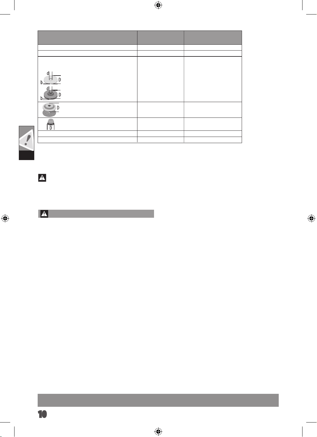
TECHNICAL DATA
Angle Grinder
WS 9-100 WS 11-125
Rated input
Rated speed 11000 min
900 W 1100 W
-1
D= Grinding disk diameter max.
d= Grinding disk hole diameter
100 mm
22,2 mm
b= Cutting disk thickness min. / max.
b= Grinding disk thickness max.
D= Grinding surface diameter max. 100 mm
D= Wiring brush diameter max. 65 mm
Thread of work spindle M 10
2 kg
125 mm
75 mm
M 14
2,3 kg
Weight according EPTA-Procedure 01/2003
1 / 3 mm
6 mm
11000 min
-1
125 mm
22,2 mm
1 / 3 mm
6 mm
DD
Deutsch
13
GB
WARNING!
Read all safety warnings and all instructions. Failure to
follow the warnings and instructions may result in electric shock,
re and/or serious injury.
Save all warnings and instructions for future reference.
ANGLE GRINDER SAFETY WARNINGS
Safety Warnings Common for Grinding, Sanding, Wire
Brushing or Abrasive Cutting-O Operations:
a) This power tool is intended to function as a grinder,
sander, wire brush or cut-o tool. Read all safety warnings,
instructions, illustrations and speci cations provided with
this power tool. Failure to follow all instructions listed below may
result in electric shock, re and/or serious injury.
b) Operations such as polishing are not recommended
to be performed with this power tool.Operations for which
the power tool was not designed may create a hazard and cause
personal injury.
c) Do not use accessories which are not speci cally
designed and recommended by the tool manufacturer. Just
because the accessory can be attached to your power tool, it does
not assure safe operation.
d) The rated speed of the accessory must be at least equal
to the maximum speed marked on the power tool. Accesso-
ries running faster than their rated speed can break and y apart.
TECHNICAL DATA
Angle Grinder
WS 11-115 WS 11-125 WS 12-125 XE
Production code
4194 01 01...
... 000001-999999
4194 11 01...
... 000001-999999
4194 31 01...
... 000001-999999
Rated input 1100 W 1100 W 1200 W
Rated speed 11000 min
-1
11000 min
-1
2800-11000 min
-1
D= Grinding disk diameter max.
d= Grinding disk hole diameter
115mm
22,2 mm
125 mm
22,2 mm
125mm
22,2 mm
b= Cutting disk thickness min. / max.
1 / 3 mm 1 / 3 mm 1 / 3 mm
b= Grinding disk thickness max.
6 mm 6 mm 6 mm
D= Grinding surface diameter max. 115 mm 125 mm 125 mm
D= Wiring brush diameter max. 75 mm 75 mm 75 mm
Thread of work spindle M 14 M 14 M 14
Weight according EPTA-Procedure 01/2003 2,3 kg 2,3 kg 2,4 kg
Noise/Vibration Information
Measured values determined according to EN 60 745. Typically, the A-weighted noise levels of the tool are:
Sound pressure level (Uncertainty K=3dB(A))
Sound power level (Uncertainty K=3dB(A))
Wear ear protectors!
90,5 dB(A)
101,5 dB(A)
90,5 dB(A)
101,5 dB(A)
90,0 dB(A)
101,0 dB(A)
Vibration total values (triaxial vector sum) determined according to EN 60745
surface grinding: Vibration emission value a
h,SG
Uncertainty K=
5,8 m/s
2
1,5 m/s
2
5,8 m/s
2
1,5 m/s
2
6,4 m/s
2
1,5 m/s
2
Disk sanding: Vibration emission value a
h,DS
Uncertainty K=
1,9 m/s
2
1,5 m/s
2
1,9 m/s
2
1,5 m/s
2
1,9 m/s
2
1,5 m/s
2
For other applications, e.g. Abrasive Cutting-O Operations or Wire Brushing other vibration values could occur.
WARNING
The vibration emission level given in this information sheet has been measured in accordance with a standardised test given in EN 60745
and may be used to compare one tool with another. It may be used for a preliminary assessment of exposure.
The declared vibration emission level represents the main applications of the tool. However if the tool is used for di erent applications,
with di erent accessories or poorly maintained, the vibration emission may di er. This may signi cantly increase the exposure level over
the total working period.
An estimation of the level of exposure to vibration should also take into account the times when the tool is switched o or when it is
running but not actually doing the job. This may signi cantly reduce the exposure level over the total working period.
Identify additional safety measures to protect the operator from the e ects of vibration such as: maintain the tool and the accessories,
keep the hands warm, organisation of work patterns.
425_009_WS9-WS11-WS12_4-2.indd 13 07.11.14 14:48
Safety Warnings Common for Grinding, Sanding, Wire
Brushing or Abrasive Cutting-O Operations:
a) This power tool is intended to function as a grinder,
sander, wire brush or cut-o tool. Read all safety warnings,
instructions, illustrations and specications provided with
this power tool. Failure to follow all instructions listed below may
result in electric shock, re and/or serious injury.
b) Operations such as polishing are not recommended to be
performed with this power tool. Operations for which the power
tool was not designed may create a hazard and cause personal injury.
c) Do not use accessories which are not specically designed
and recommended by the tool manufacturer. Just because the
accessory can be attached to your power tool, it does not assure safe
operation.
d) The rated speed of the accessory must be at least equal to
the maximum speed marked on the power tool. Accessories
running faster than their rated speed can break and y apart.
e) The outside diameter and the thickness of your accessory
must be within the capacity rating of your power tool.
Incorrectly sized accessories cannot be adequately guarded or
controlled.
f) Threaded mounting of accessories must match the grinder
spindle thread. For accessories mounted by anges, the
arbour hole of the accessory must t the locating diameter of
the ange. Accessories that do not match the mounting hardware
of the power tool will run out of balance, vibrate excessively and may
cause loss of control.
g) Do not use a damaged accessory. Before each use inspect
the accessory such as abrasive wheels for chips and cracks,
backing pad for cracks, tear or excess wear, wire brush for
loose or cracked wires. If power tool or accessory is dropped,
inspect for damage or install an undamaged accessory. After
inspecting and installing an accessory, position yourself and
bystanders away from the plane of the rotating accessory
and run the power tool at maximum no-load speed for one
minute. Damaged accessories will normally break apart during this
test time.
h) Wear personal protective equipment. Depending on
application, use face shield, safety goggles or safety glasses.
As appropriate, wear dust mask, hearing protectors, gloves
and shop apron capable of stopping small abrasive or
workpiece fragments. The eye protection must be capable of
stopping ying debris generated by various operations. The dust
mask or respirator must be capable of ltrating particles generated
by your operation. Prolonged exposure to high intensity noise may
cause hearing loss.
i) Keep bystanders a safe distance away from work area.
Anyone entering the work area must wear personal protective
equipment. Fragments of workpiece or of a broken accessory may y
away and cause injury beyond immediate area of operation.
j) Hold the power tool by insulated gripping surfaces only,
when performing an operation where the cutting accessory
may contact hidden wiring or its own cord. Cutting accessory
contacting a „live“ wire may make exposed metal parts of the power
tool „live“ and could give the operator an electric shock.
k) Position the cord clear of the spinning accessory. If you lose
control, the cord may be cut or snagged and your hand or arm may be
pulled into the spinning accessory.
l) Never lay the power tool down until the accessory has come
to a complete stop. The spinning accessory may grab the surface
and pull the power tool out of your control.
m) Do not run the power tool while carrying it at your side.
Accidental contact with the spinning accessory could snag your
1111
clothing, pulling the accessory into your body.
n) Regularly clean the power tool’s air vents. The motor’s fan
will draw the dust inside the housing and excessive accumulation of
powdered metal may cause electrical hazards.
o) Do not operate the power tool near ammable materials.
Sparks could ignite these materials.
p) Do not use accessories that require liquid coolants. Using
water or other liquid coolants may result in electrocution or shock.
Kickback and Related Warnings
Kickback is a sudden reaction to a pinched or snagged rotating wheel,
backing pad, brush or any other accessory. Pinching or snagging
causes rapid stalling of the rotating accessory which in turn causes the
uncontrolled power tool to be forced in the direction opposite of the
accessory’s rotation at the point of the binding.
For example, if an abrasive wheel is snagged or pinched by the
workpiece, the edge of the wheel that is entering into the pinch point
can dig into the surface of the material causing the wheel to climb
out or kick out. The wheel may either jump toward or away from
the operator, depending on direction of the wheel’s movement at
the point of pinching. Abrasive wheels may also break under these
conditions.
Kickback is the result of power tool misuse and/or incorrect operating
procedures or conditions and can be avoided by taking proper
precautions as given below.
a) Maintain a rm grip on the power tool and position your
body and arm to allow you to resist kickback forces. Always
use auxiliary handle, if provided, for maximum control over
kickback or torque reaction during start-up. The operator can
control torque reactions or kickback forces, if proper precautions are
taken.
b) Never place your hand near the rotating accessory. Accessory
may kickback over your hand.
c) Do not position your body in the area where power tool will
move if kickback occurs. Kickback will propel the tool in direction
opposite to the wheel’s movement at the point of snagging.
d) Use special care when working corners, sharp edges etc.
Avoid bouncing and snagging the accessory. Corners, sharp
edges or bouncing have a tendency to snag the rotating accessory and
cause loss of control or kickback.
e) Do not attach a saw chain woodcarving blade or toothed
saw blade. Such blades create frequent kickback and loss of control.
Safety Warnings Specic for Grinding and Abrasive Cutting-O
Operations:
a) Use only wheel types that are recommended for your
power tool and the specic guard designed for the selected
wheel. Wheels for which the power tool was not designed cannot be
adequately guarded and are unsafe.
b) The grinding surface of centre depressed wheels must
be mounted below the plane of the guard lip. An improperly
mounted wheel that projects through the plane of the guard lip
cannot be adequately protected.
c) The guard must be securely attached to the power tool and
positioned for maximum safety, so the least amount of wheel
is exposed towards the operator. The guard helps to protect the
operator from broken wheel fragments, accidental contact with wheel
and sparks that could ignite clothing.
d) Wheels must be used only for recommended applications.
For example: do not grind with the side of cut-o wheel.
Abrasive cut-o wheels are intended for peripheral grinding, side
forces applied to these wheels may cause them to shatter.
e) Always use undamaged wheel anges that are of correct
size and shape for your selected wheel. Proper wheel anges
support the wheel thus reducing the possibility of wheel breakage.
Flanges for cut-o wheels may be dierent from grinding wheel
anges.
f) Do not use worn down wheels from larger power tools.
Wheel intended for larger power tool is not suitable for the higher
speed of a smaller tool and may burst.
Additional Safety Warnings Specic for Abrasive Cutting-O
Operations:
a) Do not “jam” the cut-o wheel or apply excessive pressure.
Do not attempt to make an excessive depth of cut. Overstressing
the wheel increases the loading and susceptibility to twisting or
binding of the wheel in the cut and the possibility of kickback or wheel
breakage.
b) Do not position your body in line with and behind the
rotating wheel. When the wheel, at the point of operation, is
moving away from your body, the possible kickback may propel the
spinning wheel and the power tool directly at you.
c) When wheel is binding or when interrupting a cut for any
reason, switch o the power tool and hold the power tool
motionless until the wheel comes to a complete stop. Never
attempt to remove the cut-o wheel from the cut while the
wheel is in motion otherwise kickback may occur. Investigate
and take corrective action to eliminate the cause of wheel binding.
d) Do not restart the cutting operation in the workpiece. Let
the wheel reach full speed and carefully re-enter the cut. The
wheel may bind, walk up or kickback if the power tool is restarted in
the workpiece.
e) Support panels or any oversized workpiece to minimize
the risk of wheel pinching and kickback. Large workpieces tend
to sag under their own weight. Supports must be placed under the
workpiece near the line of cut and near the edge of the workpiece on
both sides of the wheel.
f) Use extra caution when making a “pocket cut” into existing
walls or other blind areas. The protruding wheel may cut gas or
water pipes, electrical wiring or objects that can cause kickback.
Safety Warnings Specic for Sanding Operations:
a) Do not use excessively oversized sanding disc paper. Follow
manufacturers recommendations, when selecting sanding
paper. Larger sanding paper extending beyond the sanding pad
presents a laceration hazard and may cause snagging, tearing of the
disc or kickback.
Safety Warnings Specic for Wire Brushing Operations:
a) Be aware that wire bristles are thrown by the brush even
during ordinary operation. Do not overstress the wires by
applying excessive load to the brush. The wire bristles can easily
penetrate light clothing and/or skin.
b) If the use of a guard is recommended for wire brushing, do
not allow any interference of the wire wheel or brush with the
guard. Wire wheel or brush may expand in diameter due to work load
and centrifugal forces.
1212
Additional Safety and Working Instructions:
When grinding metal, ying sparks are produced. Take care that no
persons are endangered. Because of the danger of re, no combustible
materials should be located in the vicinity (spark ight zone). Do not
use dust extraction.
Avoid ying sparks and sanding dust hit your body.
Never reach into the danger area of the machine when it is running.
Immediately switch o the machine in case of considerable vibrations
or if other malfunctions occur. Check the machine in order to nd out
the cause.
Under extreme conditions (e.g. smooth-grinding metals with the
arbour and vulcanized bre grinding disk), signicant contamination
can build up on the inside of the angle grinder. For safety reasons,
in such conditions a ground fault interrupter must be connected in
series. If the ground fault interrupter trips the machine must be sent
for service.
Chips and splinters must not be removed while the machine is
running.
MAINS CONNECTION
Connect only to single-phase AC system voltage as indicated on the
rating plate.
Appliances used at many dierent locations including wet room and
open air must be connected via a residual current device (FI, RCD,
PRCD) of 30mA or less.
Only plug-in when machine is switched o.
Do not let any metal parts enter the airing slots - danger of short
circuit!
Inrush currents cause short-time voltage drops. Under unfavourable
power supply conditions, other equipment may be aected. If
the system impedance of the power supply is lower than 0,2 Ohm,
disturbances are unlikely to occur.
SPECIFIED CONDITIONS OF USE
The angle grinder is intended for grinding and cutting metal, stone
and ceramic materials as well as sanding and wire brushing.
Use the cutting guard from the accessories range for cutting
application.
Please refer to the instructions supplied by the accessory manufacturer.
The machine is suitable only for working without water.
WORKING TIPS
For accessories intended to be tted with threaded hole wheel, ensure
that the thread in the wheel is long enough to accept the spindle
length.
Always use and store the cutting and grinding disks according to the
manufacturer‘s instructions.
Always use the correct guard for cutting and grinding.
The grinding surface of the centre depressed disks must be mounted
min. 2 mm below the plane of the guard lip.
The adjusting nut must be tightened before starting to work with the
machine.
Always use the auxiliary handle.
The workpiece must be xed if it is not heavy enough to be steady.
Never move the workpiece towards the rotating disk by hand.
MAINTENANCE
The ventilation slots of the machine must be kept clear at all times.
Use only AEG accessories and spare parts. Should components need
to be replaced which have not been described, please contact one of
our AEG service agents (see our list of guarantee/service addresses).
If needed, an exploded view of the tool can be ordered. Please state
the machine type printed as well as the six-digit No. on the label and
order the drawing at your local service agents or directly at:
Techtronic Industries Australia Pty Ltd
PO Box 1065
Mount Waverley VIC 3149
Tel. no. 1300 234 797
Australia
Techtronic Industries N.Z. Limited
PO Box 12-806
Penrose AUCKLAND 1642
Tel. no. 0800 234 797
New Zealand
1313
DD
ELECTRONICS
WS 12-125 XE:The built-in electronic will keep a constant speed
even under increased load.In case of overload, the rotational speed
is being reduced until machine stops.
MAINTENANCE
The ventilation slots of the machine must be kept clear at all times.
If the supply cord of this power tool is damaged, it must be
replaced by a specially prepared cord available through the service
organization.
Use only AEG accessories and spare parts. Should components need to
be replaced which have not been described, please contact one of our
AEG service agents (see our list of guarantee/service addresses).
If needed, an exploded view of the tool can be ordered. Please state
the machine type printed as well as the six-digit No. on the label
and order the drawing at your local service agents or directly at:
Techtronic Industries GmbH, Max-Eyth-Straße10, 71364Winnen-
den, Germany.
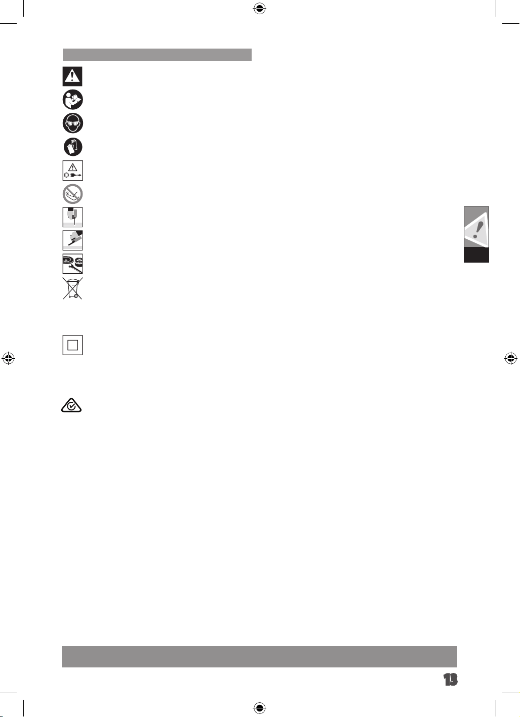
SYMBOLS
CAUTION! WARNING! DANGER!
Please read the instructions carefully before starting the
machine.
Always wear goggles when using the machine.
Wear gloves!
Always disconnect the plug from the socket before
carrying out any work on the machine.
Do not use force.
Only for cutting work.
Only for grinding.
Accessory - Not included in standard equipment, availa-
ble as an accessory.
Do not dispose of electric tools together with household was-
te material. Electric tools and electronic equipment that have
reached the end of their life must be collected separately and
returned to an environmentally compatible recycling facility.
Check with your local authority or retailer for recycling advice
and collection point.
Class II tool Tool in which protection against electric
shock does not rely on basic insulation only, but in which
additional safety precautions, such as double insulation
or reinforced insulation, are provided. There being
no provision for protective earthing or reliance upon
installation conditions.
D
425_009_WS9-WS11-WS12_4-2.indd 16 07.11.14 14:48
Regulatory Compliance mark (RCM).
This product meets applicable regulatory requirements.
Deutsch
12


Techtronic Industries Australia Pty Ltd
31 Gilby Road, Mount Waverley, VIC 3149
Australia
Techtronic Industries N.Z. Limited
2 Landing Drive, Mangere
Auckland, 2022, New Zealand
www.aegpowertools.com.au
www.aegpowertools.co.nz
AEG is a registered trademark used under
license from AB Electrolux (publ).