
Technical Support and E-Warranty Certificate www.vevor.com/support
PCP AIR COMPRESSOR
MODEL:SS-PAC02A/SS-PAC02B
We continue to be committed to provide you tools with competitive price.
"Save Half", "Half Price" or any other similar expressions used by us only represents an
estimate of savings you might benefit from buying certain tools with us compared to the major
top brands and does not necessarily mean to cover all categories of tools offered by us. You
are kindly reminded to verify carefully when you are placing an order with us if you are
actually saving half in comparison with the top major brands.

- 1 -
MODEL:SS-PAC02A/SS-PAC02B
Have product questions? Need technical support? Please feel free to
contact us:
Technical Support and E-Warranty Certificate
www.vevor.com/support
NEED HELP? CONTACT US!
This is the original instruction, please read all manual instructions
carefully before operating. VEVOR reserves a clear interpretation of our
user manual. The appearance of the product shall be subject to the
product you received. Please forgive us that we won't inform you again if
there are any technology or software updates on our product.
PCP AIR COMPRESSOR

- 2 -
Warning-To reduce the risk of injury, user must read
instructions manual carefully.
CORRECT DISPOSAL
This product is subject to the provision of European Directive
2012/19/EC. The symbol showing a wheelie bin crossed
through indicates that the product requires separate refuse
collection in the European Union. This applies to the product
and all accessories marked with this symbol. Products marked
as such may not be discarded with normal domestic waste, but
must be taken to a collection point for recycling electrical and
electronic devices
IMPORTANT SAFEGUARDS
●Portable PCPAir Gun Compressor can operated with either 220v/110v AC
(adjustable) power, or DC 12VVehicle power. Leads for both systems are supplied.
●NEVER start the Portable compressor without first having started its
cooling fan.
●The Portable compressor is designed to directly fill airguns with an
integral cylinder or buddy-bottle air source up to 0.5 litres(500cc) volume. It
should not be used for filling scuba tanks over 500cc. Any damage to the
compressor or PCP airgun caused through incorrect operation or use will
not be covered by the warranty.
●The Portable compressor has a MAXIMUM charging pressure of 300BAR
(4,500psi/30MPa) pressure.However, many PCP airguns will have a safe
working(operating) pressure that is lower than this - So DO NOT
OVER-CHARGE your PCP airgun.
● ALWAYS adhere to the airgun manufacturer' s operating instructions
when using the Portable compressor to charge your PCP airgun

- 3 -
●It is recommended that you observe the position of the needle on the 5s
pressure gauge of the PCP airgun and the unit pressure gauge at the
same time during charging. Ensure that the position does not exceed
300BAR(4500psi/30MPa). Stop blowing air when it reaches
280BAR(3750psi/28MPa)
● To avoid the unit overheating, always operate the compressor in a
well ventilated space.
● Do not disassemble the main unit of the Portable compressor- there
are no user- serviceable parts inside. However, the seals and the filter
medium and
filters in the hose assembly can be replaced with the spares provided .
●ALWAYS follow the rudimentary safety procedures when charging your
PCP airgun.
● If the supply cord is damaged, it must be replaced by a special cord or
assembly available from the manufacturer or its service agent.
● This appliance can be used by children aged from 8 years and above and
persons with reduced physical, sensory or mental capabilities or lack of
experience and knowledge if they have been given supervision or instruction
concerning use of the appliance in a safe way and understand the hazards
involved. Children shall not play with the appliance. Cleaning and user
maintenance shall not be made by children without supervision.
SAVE THESE INSTRUCTIONS
FCC Information
CAUTION:
Changes or modifications not expressly approved by the party responsible
for compliance could void the user's authority to operate the equipment!
This device complies with Part 15 of the FCC Rules. Operation is subject to
the following two conditions:
1) This product may cause harmful interference.
2)This product must accept any interference received, including
interference that may cause undesired operation.
WARNING:
Changes or modifications to this product not expressly approved by the
party.responsible for compliance could void the user's authority to operate

- 4 -
the product.
Note:
This product has been tested and found to comply with the limits for a
Class B digital device pursuant to Part 15 of the FCC Rules, These limits
are designed to provide reasonable protection against harmful interference
in a residential installation.
This product generates, uses and can radiate radio frequency energy, and
if not installed and used in accordance with the instructions, may cause
harmful interference to radio communications. However, there is no
guarantee that interference will not occur in a particular installation. If this
product does cause harmful interference to radio or television
reception,which can be determined by turning the product off and on, the
user is encouraged to try to correct the interference by one or more of the
following measures.
· Reorient or relocate the receiving antenna.
· Increase the distance between the product and receiver.
· Connect the product to an outlet on a circuit different from that to which
the receiver is connected.
· Consult the dealer or an experienced radio/TV technician for assistance.
Product parameters
Model
SS-PAC02A/SS-PAC02B
Voltage:
DC 12V for car battery or AC 120V/230V
Power
300W
Inflation
pressure
4500Psi / 30Mpa
Stop mode
AUTOSTOP
Cooling system
Built-in fan cooling
Accessories
power cord*1, 8mm Connector*1, Spare Parts
Suit*1, Crocodile Pliers*1 Manual*1
Cooling method
Fan Cooled
- 5 -
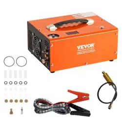
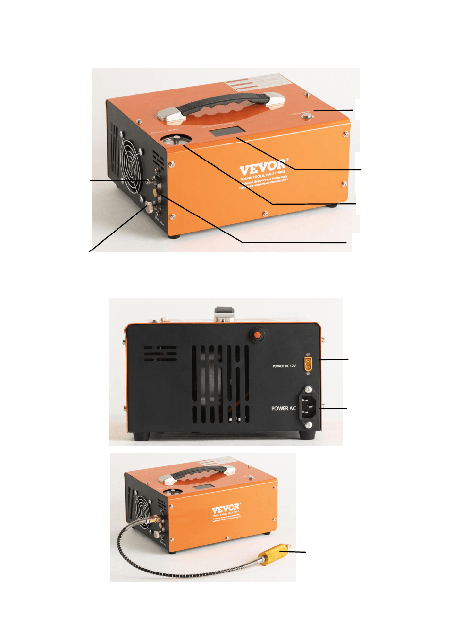
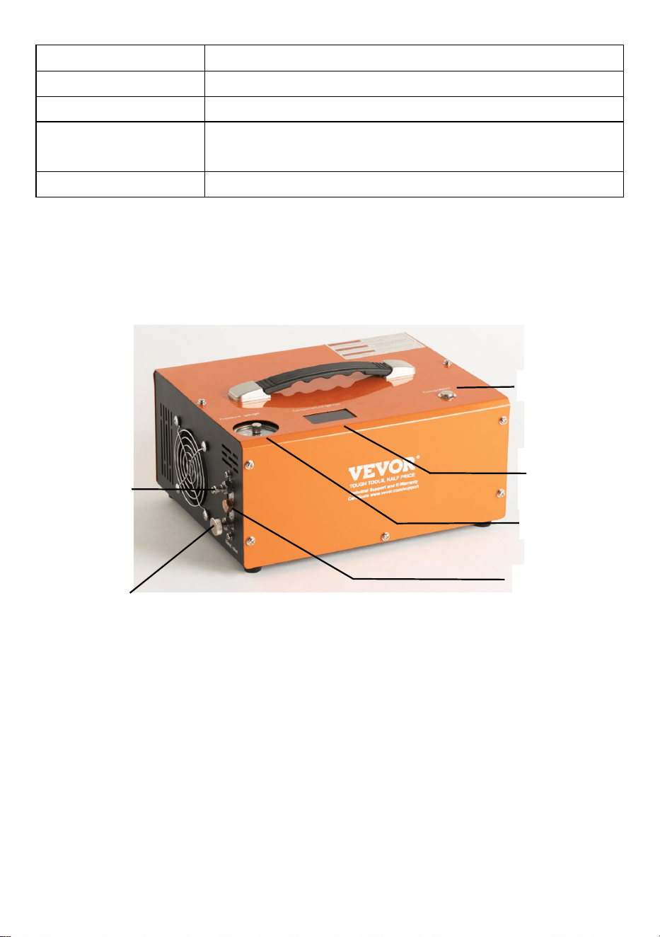
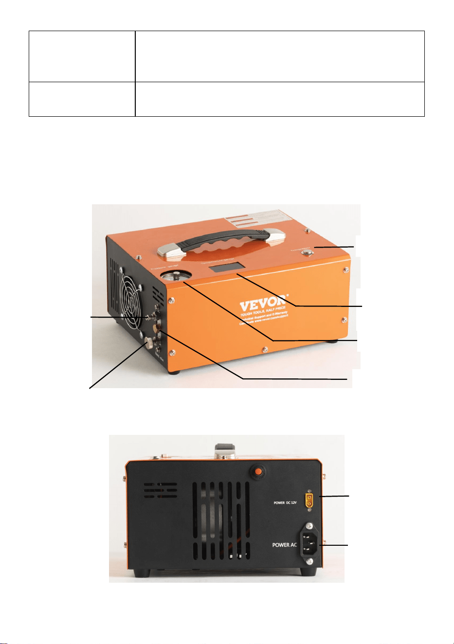
MAIN OPERATING PARTS
Power Switch
Temperature
Display
Pressure gauge
Foster-type
quick-fit air
line
Air line (hose assembly)
bleed screw
Protection Valve
DC(12V Vehicle
power) cable
socket
AC Power
Socket
Filter System
- 6 -
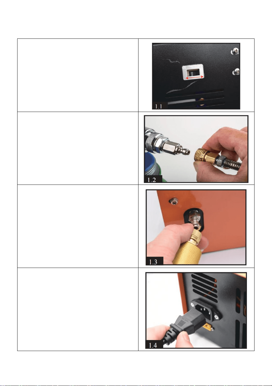
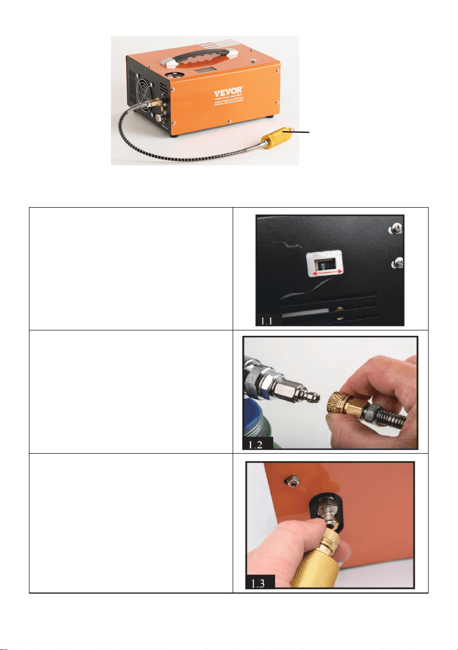
Assembly Instructions
1.First of all, you have to inspect the
working voltage by checking the
button on the bottom of the
compressor.
2.Connect the quick female coupler
to your Airgun cylinder,Air Bottle or
Airsoft products.
3)Connect another end foster to the
output on the front of compressor
via a male fitting. Make sure the
foster coupling.
4.Connect the supplied AC power
cord to the right-hand side of the
main unit and connect the three-pin
plug to the mains power outlet.
- 7 -
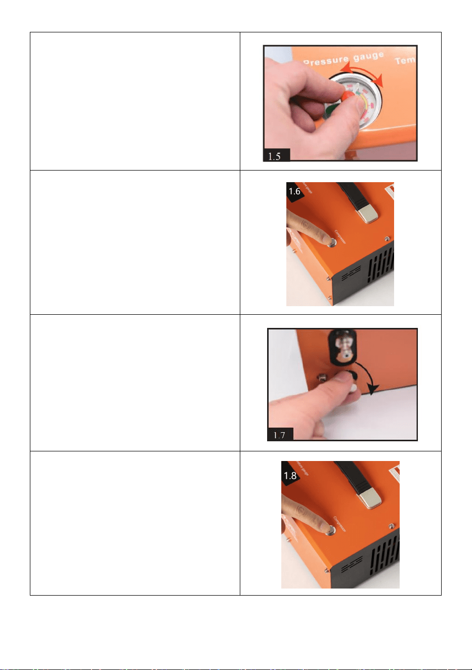
5.Manually rotate the needle of the
automatic shut- off system to the
pressure you want.
WARNING!
NEVER overfill the maximum
pressure of your cylinder and
airgun. The maximum pressure for
this compressor is 300bar
(30Mpa/4500PSI).
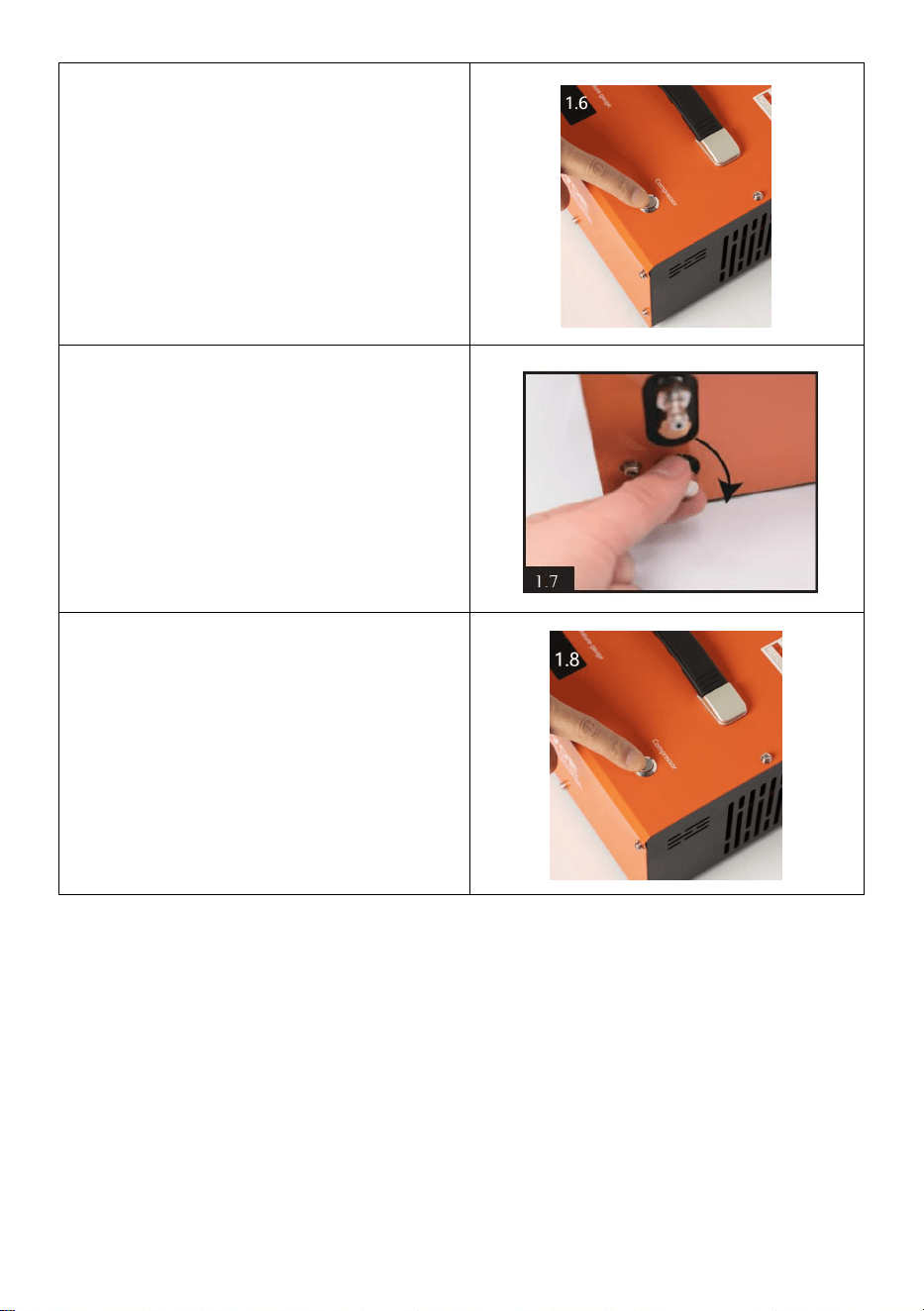
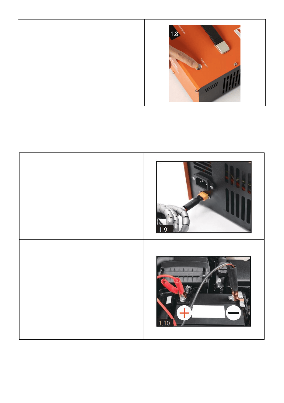
6.Press the Compressor button on
the top of the compressor to start
the cooling fan.
ATTENTION! The fan must be
running when the compressor is
working.
7.Close the air bleed valve on the
front of the main unit by turning it
clockwise. It need only be finger
tight.
8.Finally, press the POWER button
on the top of the main unit. The
compressor unit will audibly start
up and the charging process will
begin.
- 8 -
Using DC 12V Car Battery Power
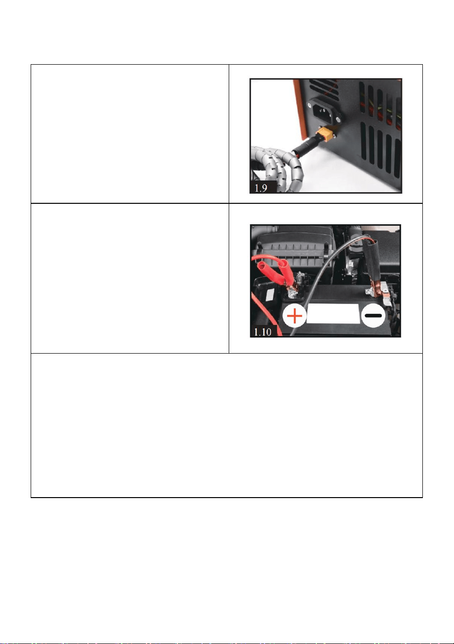
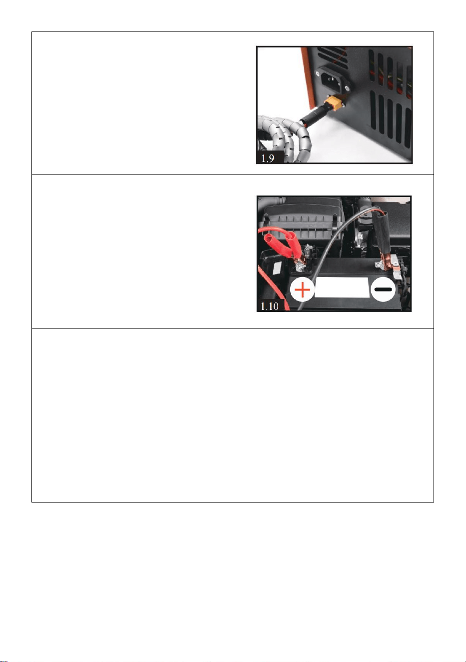
9.Insure the car engine is
running.Connect the supplied DC
power cable to the right side of the
12v socket.
Connect the red clip at the other
end of this cable to the positive (+)
terminal of the car’s12-volt
battery.Then connect the black clip
to the battery’s negative (-)
terminal.
The rest operation is same as step
6 on page 5
NOTE:
If the working temperature exceeds 80 degrees Celsius, the compressor
MUST be manually switched off, you can press the POWER button to
make the compressor stop working. Keep the cooling fan left running.
Restart the compressor function once the compressor has cooled down.
The compressor will be auto shut-off every 30 minutes to prevent
overload and overheat.You can restart the compressor by pressing the
POWER button again if air filling not finished.
Routine Maintenance
Note: we suggest you can do maintenance by changing o-rings and
clearing dirt every 50 pieces 500cc bottle filling or cumulative working 20
hours.
Insure all power is disconnected before maintenance !
- 9 -
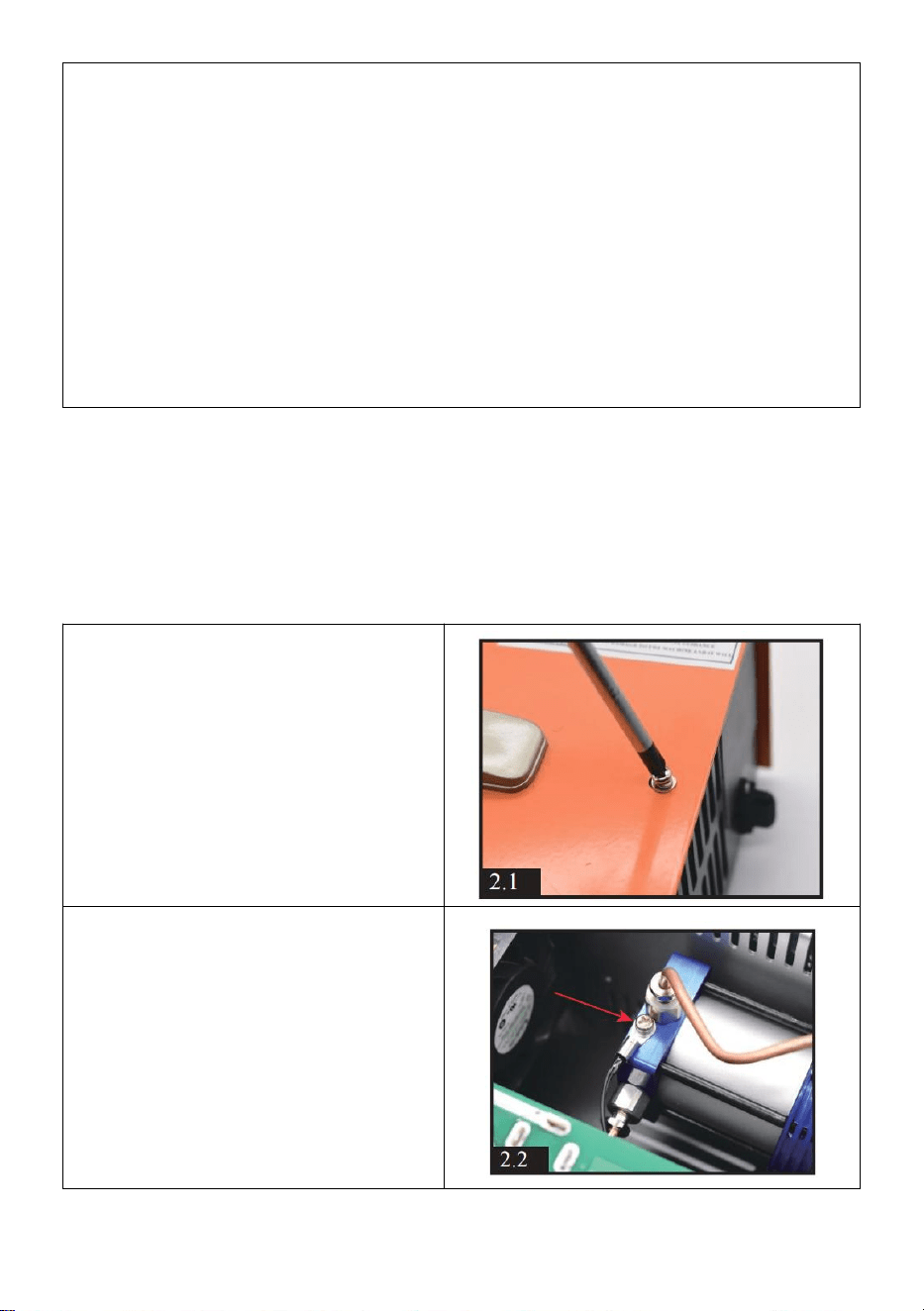
1. Loosen all 12 pieces screw on
the cabinet. (5 pieces on front, 5
pieces on rear and 2 pieces on
top ). Pick up the whole metal
cabinet carefully and slowly. Be
careful the internal wires.
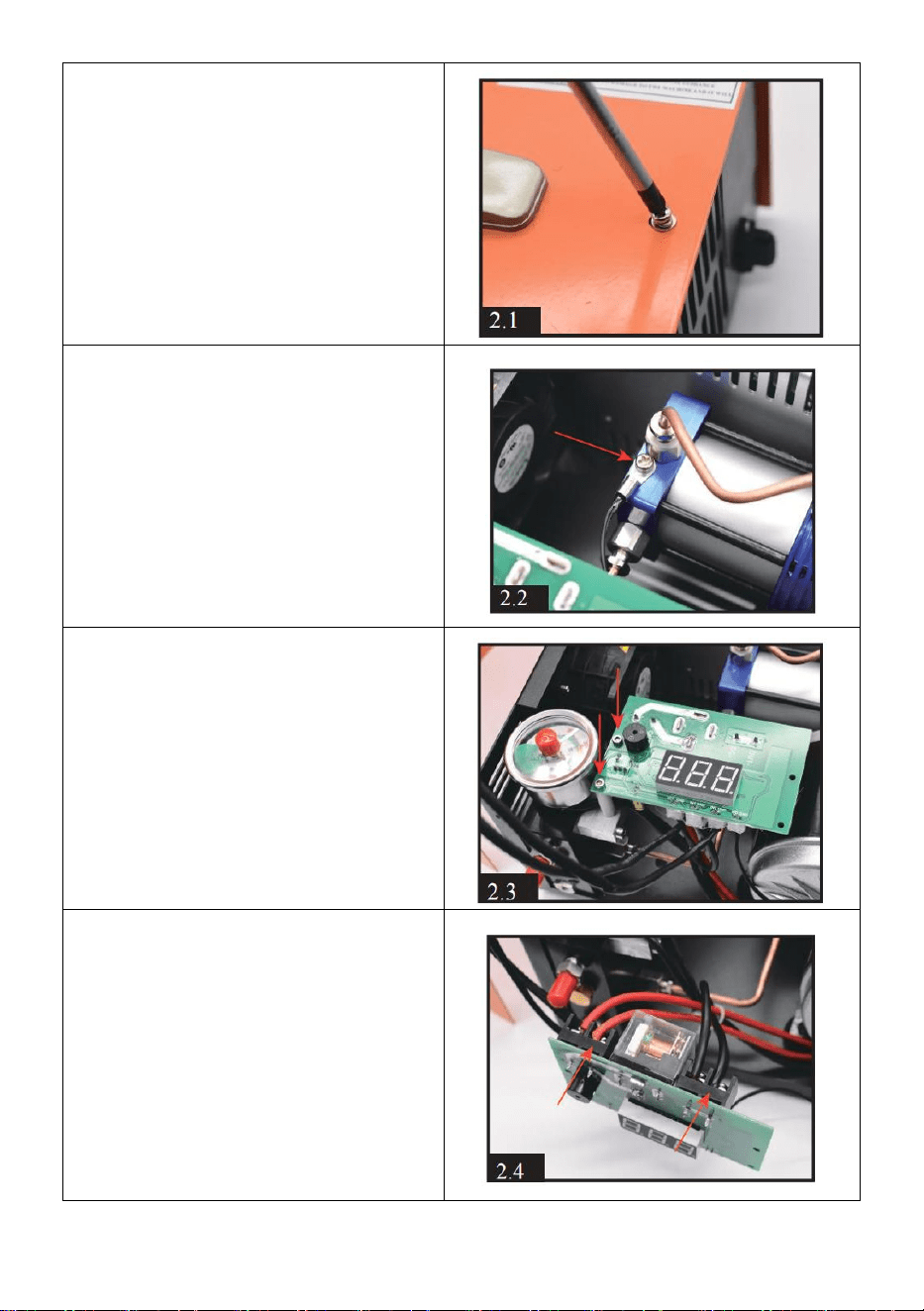
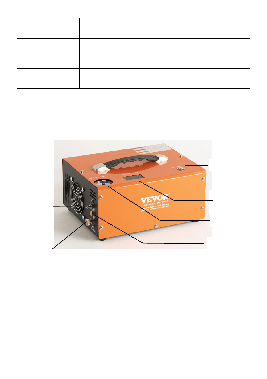
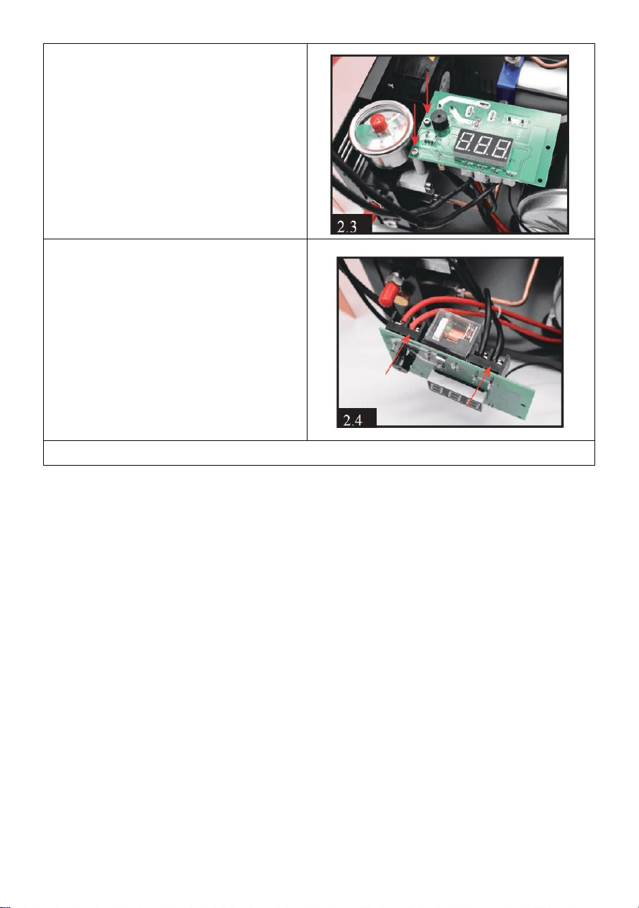
2.Loosen the temperature sensor
wire screw on the cylinder.
3.Loosen the 2 pieces screws on
the left of display.
4.Loosen the 2 pieces screws of
motor's red positive wire (OUT +)
and black negative wire(OUT-).

- 10 -
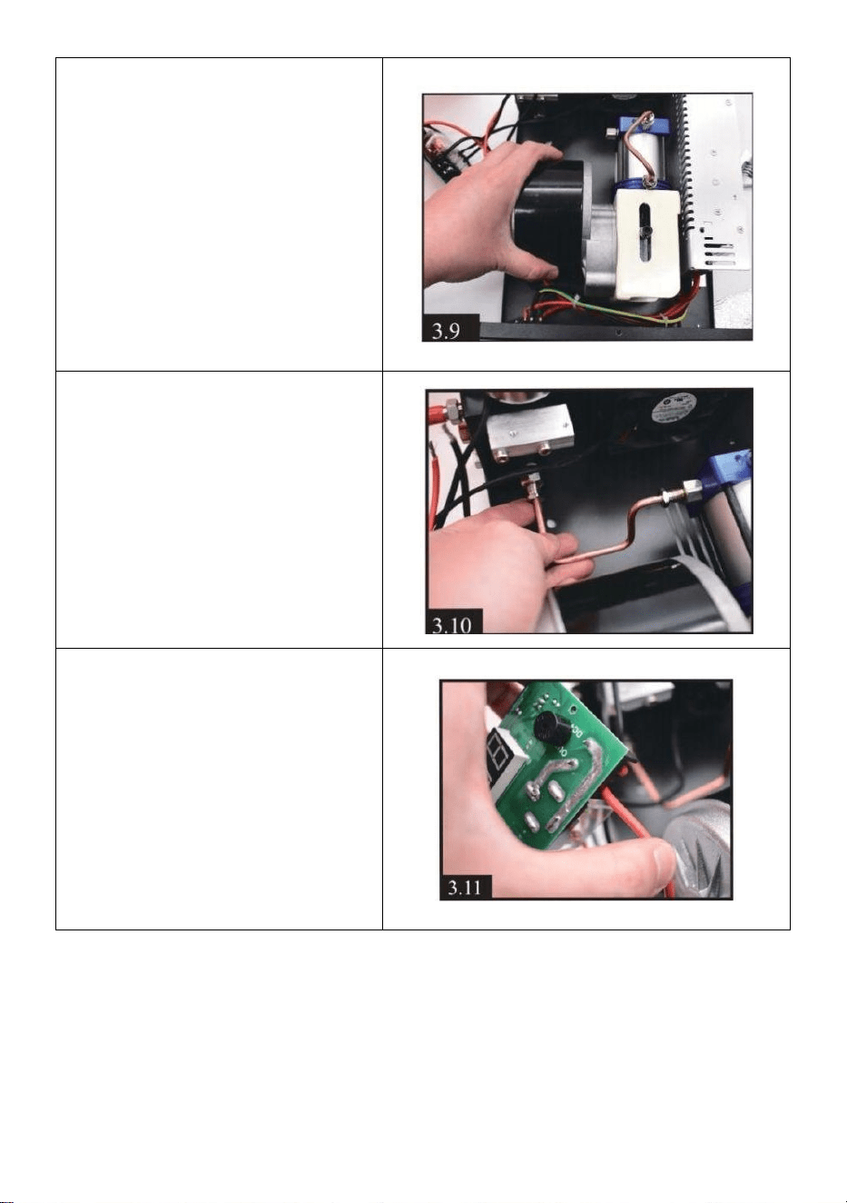
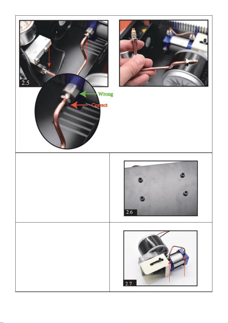
5.Loosen the 2 pieces screws of condensation tube.
6.Loosen the 4 pieces motor
screws on the bottom of
compressor.
7) You will have the whole motor
and cylinder after above
operation. Then loosen the 2
pieces screws of condensation
tube on the cylinder.
- 11 -
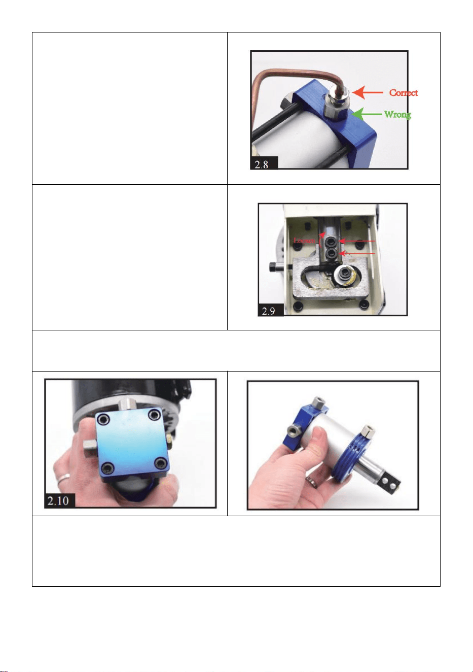
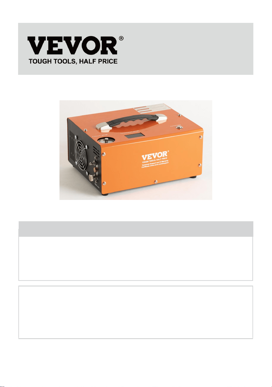
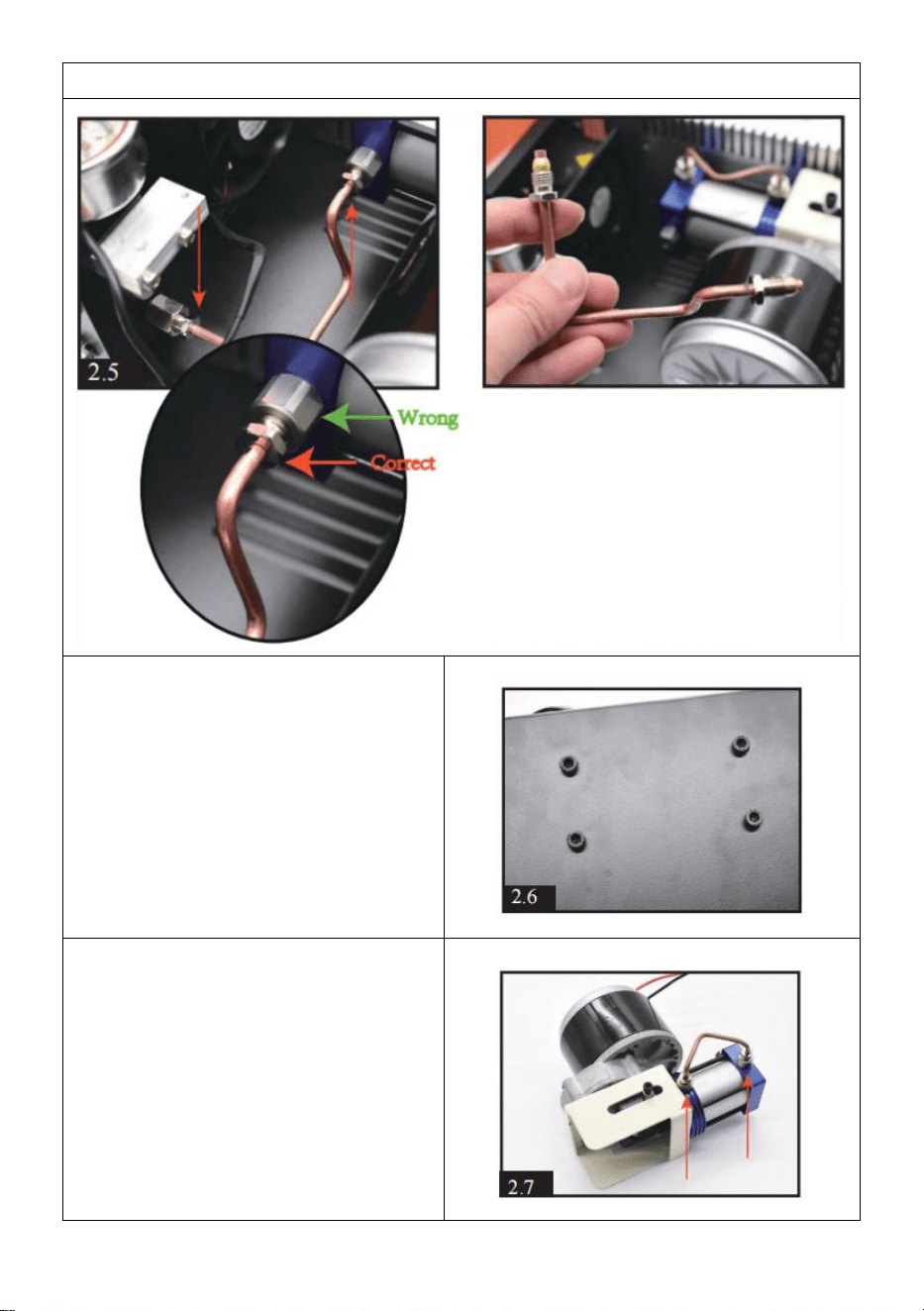
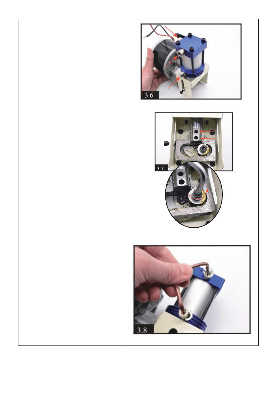
8. Same as STEP 5, need to
loosen the smaller screw near
the outside, NOT the bigger one.
9.Loosen the 2 pieces black
screws by using a hex
screwdriver on end of piston rod.
10.Loosen the 4 pieces screws on the cylinder top.You will have the
whole cylinder part.
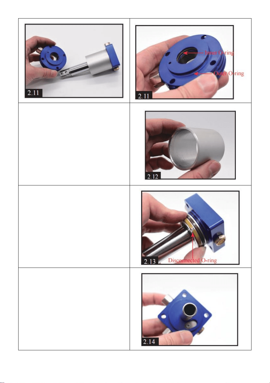
11. Take off the round shape metal part, clean all dirt and check if any
o-rings damaged.After cleaning and changing o-rings, You can evenly
apply some silicone oil or engine oil on inner o-ring.

- 12 -
12.Take off the column metal
part, clean all dirt and evenly
apply some silicone oil or engine
oil on inside.
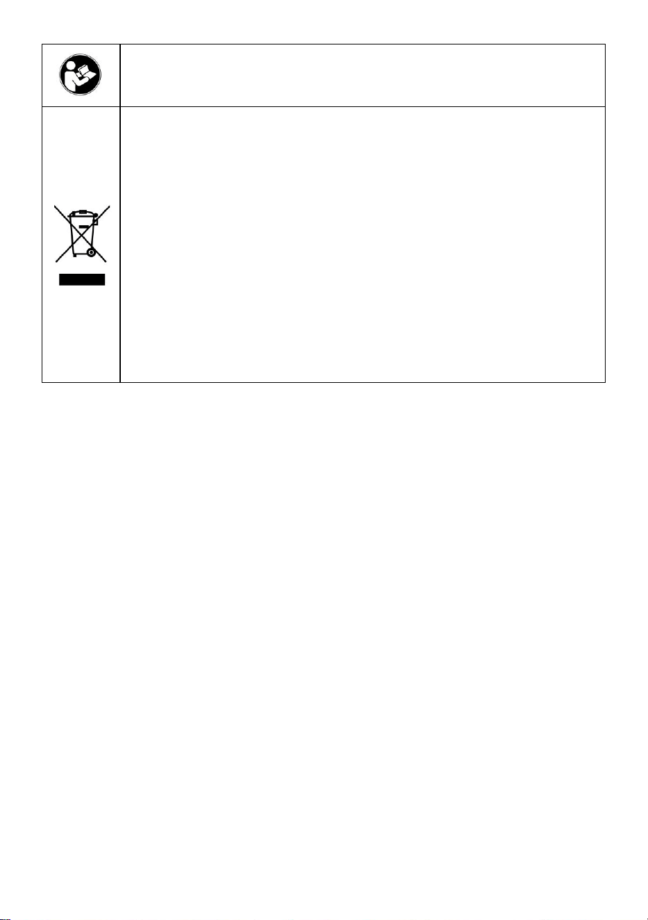
13) Separating the piston and
square metal part. Clean all dirt
and check if any o-rings
damaged.
It is normal if you find the light
gray O-ring disconnected.
14) Cleaning up the dirt inside
square part.
- 13 -
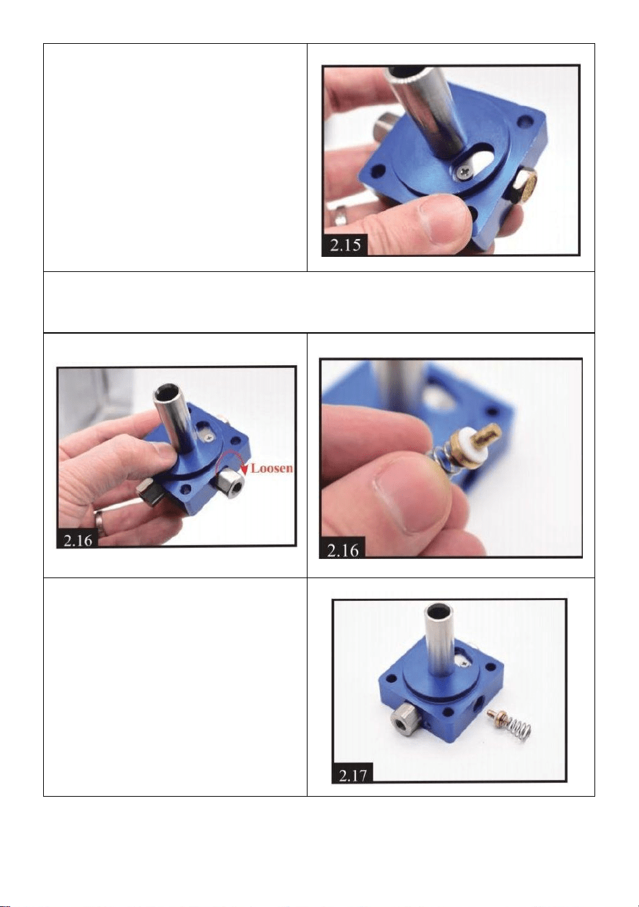
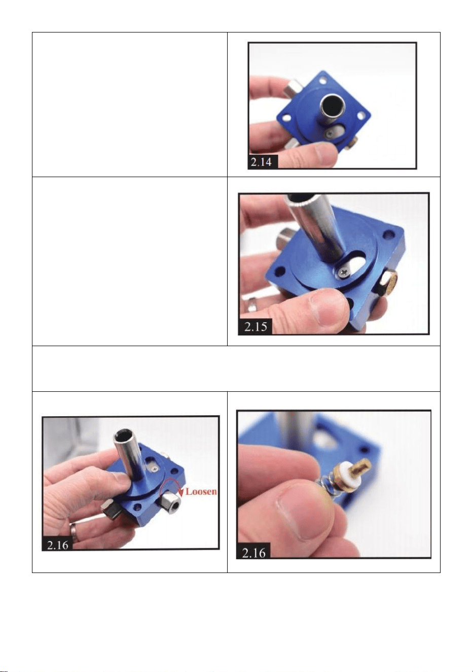
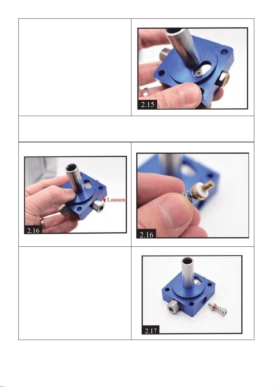
15.Loosen the screw of one-way
metal sheet. Cleaning dirt, put
back the sheet and tighten the
screw.
IMPORTANT: don't over-tighten
the screw, air needs to come out
from inside.
16) Loosen the one-way screw, you will find a one-way valve inside.
Cleaning up the dirt and check if any damages on spring and valve.
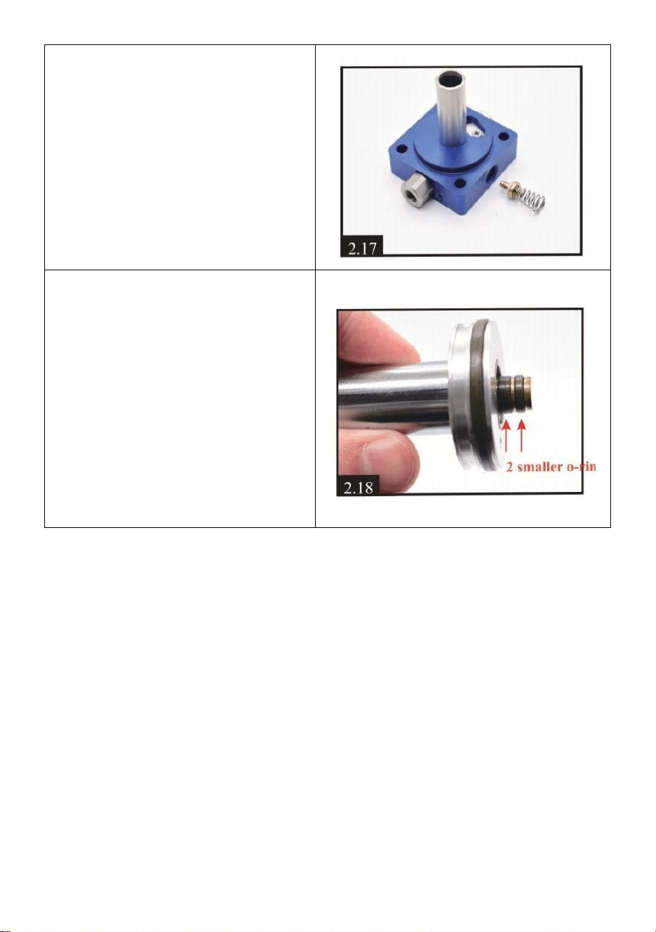
17.After cleaning, put back the
valve. Please note the metal part
faces inward, and the spring
faces outward like [2.17].Tighten
the screw, which need to be
tightened a bit.

- 14 -
18) Check if any damages on
piston o-rings. You can evenly
apply some silicone oil or engine
oil on 2 smaller o-rings.
Above is all the maintenance
content! In order to assemble it
back smoothly, we suggest that
you can browse the video while
operating Video via Youtube
-https://youtu.be/jeKo7dqSfnM
Assembly
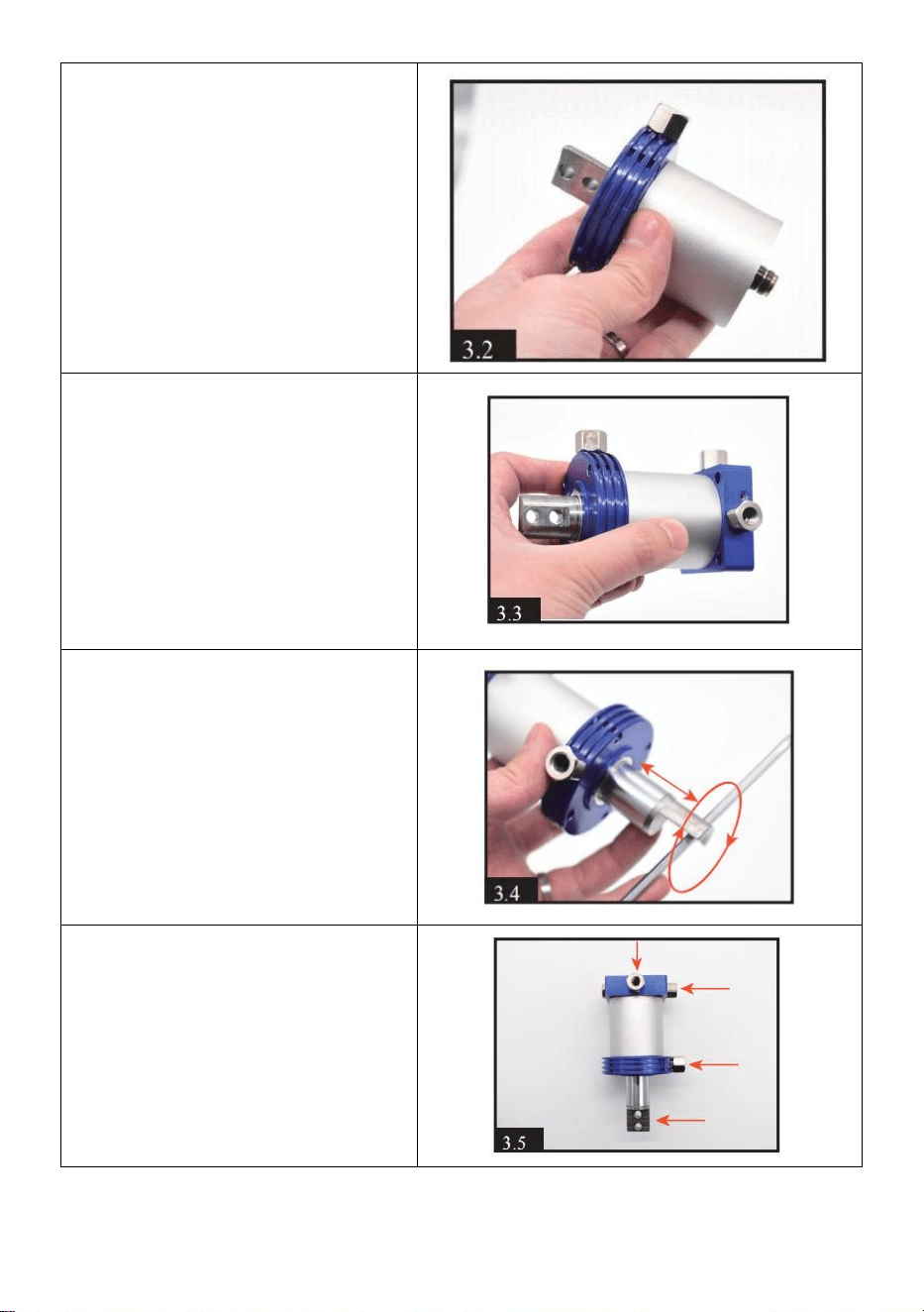
1.Setting the piston into the
column metal part. Keep the
bottom of the piston flush with
the column part.

- 15 -
2) Setting the round shape
part into the column metal
part.
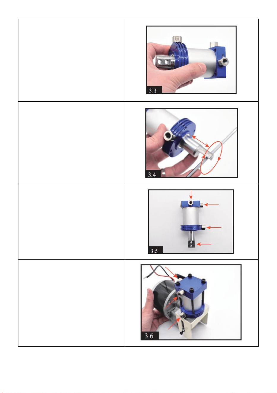
3. Setting the square part into
another end of round part.
Make sure there are no gaps
between each parts.
4.Using a tool to move the
piston back and forth and
rotate to make the internal oil
evenly spread.3-4 times will be
fine.
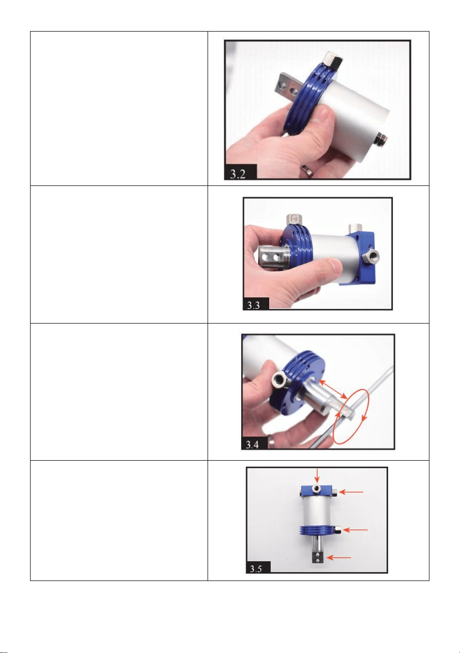
5.By turning square,round
shape part and piston, makes
the cylinder looks same as
[3.5]. Please note the direction
of each screw and piston
rod.Pull the piston rod distance
to the longest.

- 16 -
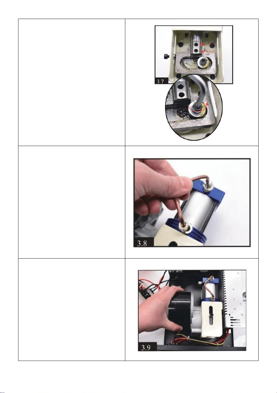
6.Install the cylinder and the
motor together, tighten 4 black
screws.
Be attention to the direction of
the 3 screws of the red arrow.
7.Tighten the 2 black screws
on piston rod and motor rod.
Note:you can adjust the
position by gently rotating the
motor screw with a hexagonal
screwdriver; which is
convenient for the installation
of 2 black screws.
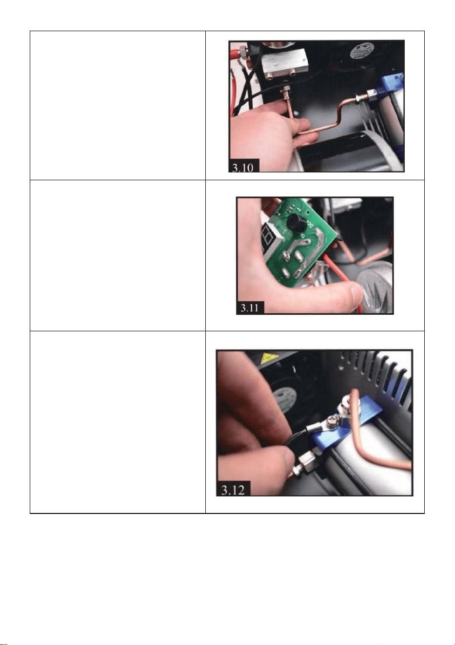
8) Install condensation tube on
cylinder.
- 17 -
9.Setting back the motor and
cylinder. Tighten 4 black
screws with motor on the
bottom of compressor.
10) Install another
condensation tube.
11.Setting back the motor wire
into display. Red to OUT+ and
black to OUT -

- 18 -
12) Setting back temperature
sensor wire on the cylinder.
13) Setting back the display.
Troubleshooting
E0- The temperature sensor is faulty.
E1- Automatically stops when the temperature exceeds 85 ° C.
E2- voltage is lower than 9.8V.
E3- The pressure button is faulty.
E4-Working time limit and pressure reach automatic stop.


- 2 -
Technique Assistance et certificat de garantie électronique
www.vevor.com/support
COMPRESSEUR D'AIR PCP
MODÈLE : SS-PAC02A/SS-PAC02B
We continue to be committed to provide you tools with competitive price.
"Save Half", "Half Price" or any other similar expressions used by us only represents an
estimate of savings you might benefit from buying certain tools with us compared to the major
top brands and does not necessarily mean to cover all categories of tools offered by us. You
are kindly reminded to verify carefully when you are placing an order with us if you are
actually saving half in comparison with the top major brands.

- 3 -
- 1 -
MODÈLE : SS-PAC02A/SS-PAC02B
Have product questions? Need technical support? Please feel free to
contact us:
Technical Support and E-Warranty Certificate
www.vevor.com/support
NEED HELP? CONTACT US!
This is the original instruction, please read all manual instructions
carefully before operating. VEVOR reserves a clear interpretation of our
user manual. The appearance of the product shall be subject to the
product you received. Please forgive us that we won't inform you again if
there are any technology or software updates on our product.
PCP AIR COMPRESSOR

- 2 -
Avertissement : Pour réduire le risque de blessure, l'utilisateur
doit lire attentivement le manuel d'instructions.
ÉLIMINATION CORRECTE
Ce produit est soumis aux dispositions de la directive
européenne 2012/19/CE. Le symbole représentant une
poubelle barrée indique que le produit nécessite une collecte
sélective des déchets dans l'Union européenne. Ceci
s'applique au produit et à tous les accessoires marqués de ce
symbole. Les produits marqués comme tels ne peuvent pas
être jetés avec les ordures ménagères normales, mais doivent
être déposés dans un point de collecte pour le recyclage des
appareils électriques et électroniques.
GARANTIES IMPORTANTES
●Portable PCPAir Pistolet Compresseur peut exploité avec soit _ 220 V/110 V CA
(Ajustable ) pouvoir , ou CC 12VVéhicule pouvoir . Conduit_ pour les deux
systèmes sont fourni.
●JAMAIS commencer le Portable compresseur sans d' abord ayant
commencé c'est refroidissement ventilateur.
●Le Portable compresseur est conçu à directement remplir armes
aériennes avec un intégral cylindre ou copain-bouteille air source en haut à
0,5 litres (50 0 cc ) volume . Il devrait pas être utilisé pour remplissage
scaphandre autonome réservoirs sur 500cc. N'importe lequel dommage à le
compresseur ou PCP pistolet à air causé à travers Incorrect opération ou
utiliser volonté pas être couvert par le garantie.
●Le Portable compresseur a un MAXIMUM mise en charge pression de 300
BARS (4 500 psi /30 MPa ) pression . Cependant , beaucoup PCP armes à air
comprimé volonté avoir un sûr travailler ( opérer ) pression que est inférieur
que ce - Donc FAIRE PAS _ SURCHARGE _ ton PCP pistolet à air .

- 3 -
● TOUJOURS adhérer à le pistolet à air fabricant ' s en fonctionnement
instructions lors de l'utilisation le Portable compresseur à charge ton
PCP pistolet à air
●Il est recommandé que toi observer le position de le aiguille sur le 5s
pression jauge de le PCP pistolet à air et le unité pression jauge à le _
même temps pendant la charge . Assurer que le position fait pas
dépasser 300 BAR (4 500 psi /30 MPa ). Arrêt souffler air quand il
atteint 280 BAR (3 750 psi /28 MPa )
● À éviter le unité surchauffe , toujours fonctionner le compresseur dans
un bien aéré espace.
● Faire pas démonter le principal unité de le Portable compresseur - là
sont aucun utilisateur - réparable les pièces à l'intérieur . Cependant , le
scellés et le filtre moyen et
filtres dans le tuyau assemblée peut être remplacé avec le _ piècesde rechange
fourni .
●TOUJOURS suivre le rudimentaire sécurité procédures _ quand mise en
charge ton Arme à air PCP .
● Si le cordon d'alimentation est endommagé, il doit être remplacé par un
cordon ou un ensemble spécial disponible auprès du fabricant ou de son
agent de service.
● Cet appareil peut être utilisé par des enfants âgés de 8 ans et plus et des
personnes ayant des capacités physiques, sensorielles ou mentales réduites
ou un manque d'expérience et de connaissances s'ils ont reçu une
surveillance ou des instructions concernant l'utilisation de l'appareil en toute
sécurité et comprennent les dangers impliqués. Les enfants ne doivent pas
jouer avec l'appareil. Le nettoyage et l'entretien par l'utilisateur ne doivent
pas être effectués par des enfants sans surveillance.
CONSERVEZ CES INSTRUCTIONS
Informations FCC
PRUDENCE:
Les changements ou modifications non expressément approuvés par la
partie responsable de la conformité pourraient annuler le droit de
l'utilisateur à utiliser l'équipement !
Cet appareil est conforme à la partie 15 des règles FCC. L’exploitation est

- 4 -
soumise aux deux conditions suivantes :
1) Ce produit peut provoquer des interférences nuisibles.
2) Ce produit doit accepter toute interférence reçue, y compris les
interférences susceptibles de provoquer un fonctionnement indésirable.
AVERTISSEMENT:
Les changements ou modifications apportés à ce produit non
expressément approuvés par la partie responsable de la conformité
pourraient annuler le droit de l'utilisateur à utiliser le produit.
Note:
Ce produit a été testé et jugé conforme aux limites d'un appareil numérique
de classe B conformément à la partie 15 des règles FCC. Ces limites sont
conçues pour fournir une protection raisonnable contre les interférences
nuisibles dans une installation résidentielle.
Ce produit génère, utilise et peut émettre de l'énergie radiofréquence et,
s'il n'est pas installé et utilisé conformément aux instructions, il peut
provoquer des interférences nuisibles aux communications radio.
Cependant, rien ne garantit que des interférences ne se produiront pas
dans une installation particulière. Si ce produit provoque des interférences
nuisibles à la réception radio ou télé, ce qui peut être déterminé en
éteignant et rallumant le produit, l'utilisateur est encouragé à essayer de
corriger les interférences en prenant une ou plusieurs des mesures
suivantes.
· Réorientez ou déplacez l'antenne de réception.
· Augmentez la distance entre le produit et le récepteur.
· Connectez le produit à une prise sur un circuit différent de celui auquel le
récepteur est connecté.
· Consultez le revendeur ou un technicien radio/TV expérimenté pour
obtenir de l'aide.
Paramètres du produit
Modèle
SS-PAC02A/SS-PAC02B
tension:
DC 12 V pour batterie de voiture ou AC 120 V/230 V.
Pouvoir
300W
Pression de
gonflage
4500psi/30mpa
Mode arrêt
AUTO-STOP
- 5 -
Système de
refroidissement
Refroidissement par ventilateur intégré
Accessoires _
cordon d'alimentation * 1, connecteur 8 mm * 1,
combinaison de pièces de rechange * 1, pince
crocodile * 1 manuel * 1
Méthode de
refroidissement
Refroidi par ventilateur
PRINCIPALES PIÈCES DE FONCTIONNEMENT
Power Switch
Temperature
Display
Pressure gauge
Foster-type
quick-fit air
line
Air line (hose assembly)
bleed screw
Protection Valve

- 6 -
Instructions de montage
1 . D'abord tout, vous devez
inspecter le fonctionnement tension
en vérifiant le bouton en bas de le
compresseur.
DC(12V Vehicle
power) cable
socket
AC Power
Socket
Filter System

- 7 -
2 . Connectez le coupleur femelle
rapide à votre cylindre Airgun ,
bouteille d'air ou Produits Airsoft .
3 ) Connectez un autre foyer
d'extrémité au sortir sur le devant de
compresseur via un mâle raccord .
S'assurer le couplage nourricier .
4 . Connectez le Cordon
d'alimentation secteur à droite côté
de le principal unité et connecter la
fiche à trois broches à la prise
secteur t .
5 . Manuellement tourner le aiguille
de le arrêt automatique système à la
pression souhaitée.
AVERTISSEMENT!
JAMAIS déborder le maximum
pression de votre cylindre et votre
arme à air comprimé. La pression
maximale pour cela compresseur
est de 300 bars (30 Mpa /4500
PSI ).
- 8 -
6. Appuyez sur le bouton
Compresseur situé sur le dessus du
compresseur pour démarrer le
ventilateur de refroidissement.
ATTENTION! Le ventilateur doit
fonctionner lorsque le compresseur
fonctionne .
7 . Fermez la vanne de purge d'air
du devant de l'unité principale en la
tournant dans le sens des aiguilles
d'une montre. Il suffit de le serrer
avec les doigts.
8 . Enfin , appuyez sur le bouton
POWER en haut de le principal
unité . Le compresseur unité
volonté démarre de manière
audible et le processus de charge
commence.
Utilisation de l'alimentation de la batterie de voiture
DC 12 V
- 9 -
9 . Assurer la voiture Le moteur
tourne. Connectez le câble
d'alimentation CC fourni au côté
droit de la prise 12 V.
Connectez le clip rouge à l'autre
extrémité de ce câble à la borne
positive (+) du voiture 12 volts
Batterie. Connectez ensuite le clip
noir à la borne négative (-) de la
batterie.
L'opération restante est la même
que celle de l'étape 6 à la page 5.
NOTE:
Si la température de fonctionnement dépasse 80 degrés Celsius, le
compresseur DOIT être éteint manuellement, vous pouvez appuyer sur
le bouton POWER pour arrêter le compresseur. Laissez le ventilateur de
refroidissement en marche. Redémarrez la fonction du compresseur une
fois que le compresseur a refroidi.
Le compresseur s'éteindra automatiquement toutes les 30 minutes pour
éviter la surcharge et la surchauffe. Vous pouvez redémarrer le
compresseur en appuyant à nouveau sur le bouton POWER si le
remplissage d'air n'est pas terminé.
Maintenance de routine
Remarque : nous vous suggérons d'effectuer l'entretien en changeant les
joints toriques et en éliminant la saleté toutes les 50 pièces de remplissage
de bouteille de 500 cc ou en travaillant 20 heures cumulées.
Assurez-vous que toute l’alimentation est coupée avant l’entretien !

- 10 -
1 . Desserrez les 12 vis du
meuble. (5 pièces devant, 5
pièces à l'arrière et 2 pièces sur
le dessus). Ramassez toute
l'armoire métallique avec
précaution et lentement. Faites
attention aux fils internes.
2 . Desserrer le fil de capteur de
température visser le cylindre.
3 . Desserrez les 2 vis à gauche
de l'écran.
4 . Desserrez les 2 vis du fil
positif rouge (OUT +) et du fil
négatif noir (OUT-) du moteur.
- 11 -
5 . Desserrer les 2 vis du tube de condensation.
6 . Desserrez les 4 vis du moteur
au bas du compresseur.
7) Vous aurez l'ensemble du
moteur et du cylindre après
l'opération ci-dessus. Desserrez
ensuite les 2 vis du tube de
condensation sur le cylindre.

- 12 -
8 . Identique à l'ÉTAPE 5, il faut
desserrer la plus petite vis près
de l’extérieur, PAS la plus grosse.
9 . Desserrez les 2 vis noires à
l'aide d'un tournevis hexagonal à
l'extrémité de la tige de piston.
dix . Desserrez les 4 vis sur le dessus du cylindre. Vous aurez toute la
partie cylindre.
11 . Retirez la partie métallique de forme ronde, nettoyez toute la saleté
et vérifiez si des joints toriques sont endommagés. Après avoir nettoyé
et changé les joints toriques, vous pouvez appliquer uniformément de
l'huile de silicone ou de l'huile moteur sur le joint torique intérieur .
- 13 -
12 . Retirez la partie métallique
de la colonne, nettoyez toute la
saleté et appliquez uniformément
un peu d'huile de silicone ou
d'huile moteur à l'intérieur.
14) Séparation du piston et de la
pièce métallique carrée. Nettoyez
toute la saleté et vérifiez si des
joints toriques sont
endommagés.
Il est normal que le joint torique
gris clair soit déconnecté.
14) Nettoyer la saleté à l'intérieur
de la partie carrée .

- 14 -
15 . Desserrez la vis de la tôle à
sens unique. En nettoyant la
saleté, remettez la tôle et serrez
la vis.
IMPORTANT : ne serrez pas trop
la vis, il faut que l'air sorte de
l'intérieur.
16) Desserrez la vis unidirectionnelle, vous trouverez une valve
unidirectionnelle à l'intérieur. Nettoyez la saleté et vérifiez s'il y a des
dommages sur le ressort et la valve.
17 . Après le nettoyage, remettez
la valve en place. Veuillez noter
que la partie métallique est
tournée vers l'intérieur et que le
ressort est tourné vers l'extérieur
comme [2.17]. Serrez la vis, qui
doit être serrée un peu plus. peu .

- 15 -
18) Vérifiez s'il y a des
dommages sur les joints toriques
du piston. Vous pouvez appliquer
uniformément un peu d'huile de
silicone ou d'huile moteur sur 2
joints toriques plus petits.
Ci-dessus se trouve tout le
contenu de la maintenance ! Afin
de le remonter en douceur, nous
vous suggérons de parcourir la
vidéo tout en fonctionnant Vidéo
via Youtube
-https://youtu.be/jeKo7dqSfnM
Assemblée
1 . Mise en place du piston
dans la partie métallique de la
colonne. Gardez le bas du
piston au ras de la partie de la
colonne.

- 16 -
2) Placer la pièce de forme
ronde dans la pièce
métallique de la colonne.
3 . Placer la partie carrée dans
une autre extrémité de la partie
ronde. Assurez-vous qu'il n'y a
pas d'espace entre chaque
pièce.
4 . Utiliser un outil pour
déplacer le piston d'avant en
arrière et le faire tourner pour
que l'huile interne soit répartie
uniformément. 3 à 4 fois
suffiront.
5 . En tournant la pièce de
forme carrée et ronde et le
piston, le cylindre ressemble à
[3.5]. Veuillez noter le sens de
chaque vis et tige de piston.
Tirez la distance de la tige de
piston au maximum.

- 17 -
6 . Installez le cylindre et le
moteur ensemble, serrez 4 vis
noires.
Soyez attentif au sens des 3
vis de la flèche rouge.
7 . Serrez les 2 vis noires sur le
piston tige et tige moteur.
Remarque : vous pouvez
régler la position en tournant
doucement la vis du moteur
avec un tournevis hexagonal ;
ce qui est pratique pour
l'installation de 2 vis noires .
8) Installez le tube de
condensation sur le cylindre.

- 18 -
9 . Recul du moteur et du
cylindre. Serrez les 4 vis noires
avec le moteur au bas du
compresseur.
10) Installez un autre tube de
condensation.
11 . Remettre le fil du moteur
dans l'affichage. Rouge vers
OUT+ et noir vers OUT -

- 19 -
12) Recul du fil du capteur de
température sur le cylindre.
13) Recul de l'affichage.
Dépannage
E0- Le capteur de température est défectueux .
E1- S'arrête automatiquement lorsque la température dépasse 85°C .
est inférieure à 9,8 V.
E3- Le bouton pression est défectueux .
E4-Le délai de travail et la pression atteignent l'arrêt automatique .


- 2 -
Technisch Support- und E-Garantie-Zertifikat www.vevor.com/support
PCP-LUFTKOMPRESSOR
MODELL: SS-PAC02A/SS-PAC02B
We continue to be committed to provide you tools with competitive price.
"Save Half", "Half Price" or any other similar expressions used by us only represents an
estimate of savings you might benefit from buying certain tools with us compared to the major
top brands and does not necessarily mean to cover all categories of tools offered by us. You
are kindly reminded to verify carefully when you are placing an order with us if you are
actually saving half in comparison with the top major brands.

- 1 -
MODELL: SS-PAC02A/SS-PAC02B
Have product questions? Need technical support? Please feel free to
contact us:
Technical Support and E-Warranty Certificate
www.vevor.com/support
NEED HELP? CONTACT US!
This is the original instruction, please read all manual instructions
carefully before operating. VEVOR reserves a clear interpretation of our
user manual. The appearance of the product shall be subject to the
product you received. Please forgive us that we won't inform you again if
there are any technology or software updates on our product.
PCP AIR COMPRESSOR
- 2 -
Warnung: Um das Verletzungsrisiko zu verringern, muss der
Benutzer die Bedienungsanleitung sorgfältig lesen.
RICHTIGE ENTSORGUNG
Dieses Produkt unterliegt den Bestimmungen der
europäischen Richtlinie 2012/19/EG. Das Symbol einer
durchgestrichenen Mülltonne weist darauf hin, dass das
Produkt in der Europäischen Union einer getrennten
Müllsammlung bedarf. Dies gilt für das Produkt und alle
Zubehörteile, die mit diesem Symbol gekennzeichnet sind. Als
solche gekennzeichnete Produkte dürfen nicht über den
normalen Hausmüll entsorgt werden, sondern müssen an
einer Sammelstelle für das Recycling von Elektro- und
Elektronikgeräten abgegeben werden
WICHTIGE SICHERHEITSMASSNAHMEN
●tragbar PCP Luft Pistole Kompressor dürfen betrieben mit entweder _ 220 V/110
V Wechselstrom
( einstellbar ) Leistung, oder Gleichstrom 12VFahrzeug Leistung. Führt _ für beide
Systeme Sind geliefert.
●NIEMALS Start Die tragbar Kompressor ohne Erste _ haben gestartet
es ist Kühlung Lüfter.
●Der tragbar Kompressor Ist entworfen Zu direkt füllen Luftgewehre _ mit
ein Integral Zylinder oder Kumpel-Flasche Luft Quelle hoch Zu 0,5 Liter (50 0
ccm ) Lautstärke . Es sollen nicht Sei gebraucht für Füllung Tauchen
Panzer über 500cc. Beliebig Schaden Zu Die Kompressor oder PCP
Luftgewehr verursacht durch falsch Betrieb oder verwenden Wille nicht Sei
bedeckt von Die Garantie.
●Der tragbar Kompressor hat A MAXIMAL Aufladen Druck von 300BAR (4.500
psi /30 MPa ) Druck . Jedoch , viele PCP Luftgewehre Wille haben A sicher

- 3 -
arbeiten ( operieren ) Druck Das Ist untere als Das - Also TUN NICHT _
ÜBERLADUNG _ dein PCP Luftgewehr .
● STETS haften Zu Die Luftgewehr Hersteller ' S Betriebs
Anweisungen beim Benutzen Die tragbar Kompressor Zu Aufladung dein
PCP Luftgewehr
●Es Ist empfohlen Das Du beobachten Die Position von Die Nadel An Die 5s
Druck Messgerät von Die PCP Luftgewehr Und Die Einheit Druck
Messgerät bei Die _ Dasselbe Zeit während des Ladevorgangs .
Sicherstellen Das Die Position tut nicht überschreiten 300 BAR (4500 psi
/30 MPa ). Stoppen weht Luft Wann Es erreicht 280 BAR (3750 psi /28
MPa )
● Zu vermeiden Die Einheit Überhitzung , stets arbeiten Die Kompressor
In A gut belüftet Raum.
● Tun nicht zerlegen Die hauptsächlich Einheit von Die tragbar
Kompressor - Dort Sind kein Benutzer – wartungsfähig Teile innen .
Jedoch , Die Siegel Und Die Filter Mittel Und
Filter In Die Schlauch Montage dürfen Sei ersetzt mit Die_ Ersatzteile bereitgestellt .
●STETS folgen Die rudimentär Sicherheit Verfahren _ Wann Aufladen dein
PCP- Luftgewehr .
● Wenn das Netzkabel beschädigt ist, muss es durch ein spezielles Kabel
oder eine spezielle Baugruppe ersetzt werden, die beim Hersteller oder
seinem Kundendienst erhältlich ist.
● Dieses Gerät kann von Kindern ab 8 Jahren und darüber sowie von
Personen mit eingeschränkten körperlichen, sensorischen oder geistigen
Fähigkeiten oder einem Mangel an Erfahrung und Wissen verwendet werden,
wenn sie beaufsichtigt oder in die sichere Verwendung des Geräts
eingewiesen wurden und das Gerät verstehen damit verbundene Gefahren.
Kinder dürfen nicht mit dem Gerät spielen. Reinigung und Benutzerwartung
dürfen nicht von Kindern ohne Aufsicht durchgeführt werden.
ANLEITUNG AUFBEWAHREN
FCC-Informationen
VORSICHT:
Änderungen oder Modifikationen, die nicht ausdrücklich von der für die

- 4 -
Einhaltung verantwortlichen Partei genehmigt wurden, können zum
Erlöschen der Berechtigung des Benutzers zum Betrieb des Geräts führen!
Dieses Gerät entspricht Teil 15 der FCC-Bestimmungen. Der Betrieb
unterliegt den folgenden zwei Bedingungen:
1) Dieses Produkt kann schädliche Störungen verursachen.
2) Dieses Produkt muss alle empfangenen Störungen akzeptieren,
einschließlich Störungen, die zu unerwünschtem Betrieb führen können.
WARNUNG:
Änderungen oder Modifikationen an diesem Produkt, die nicht ausdrücklich
von der für die Einhaltung verantwortlichen Partei genehmigt wurden,
können zum Erlöschen der Berechtigung des Benutzers zum Betrieb des
Produkts führen.
Notiz:
Dieses Produkt wurde getestet und entspricht den Grenzwerten für ein
digitales Gerät der Klasse B gemäß Teil 15 der FCC-Bestimmungen. Diese
Grenzwerte sollen einen angemessenen Schutz vor schädlichen
Störungen in einer Wohnanlage bieten.
Dieses Produkt erzeugt und verwendet Hochfrequenzenergie und kann
diese ausstrahlen. Wenn es nicht gemäß den Anweisungen installiert und
verwendet wird, kann es schädliche Störungen der Funkkommunikation
verursachen. Es gibt jedoch keine Garantie dafür, dass bei einer
bestimmten Installation keine Störungen auftreten. Wenn dieses Produkt
schädliche Störungen beim Radio- oder Fernsehempfang verursacht, was
durch Aus- und Einschalten des Produkts festgestellt werden kann, wird
dem Benutzer empfohlen, zu versuchen, die Störung durch eine oder
mehrere der folgenden Maßnahmen zu beheben.
· Richten Sie die Empfangsantenne neu aus oder versetzen Sie sie.
· Erhöhen Sie den Abstand zwischen Produkt und Empfänger.
· Schließen Sie das Produkt an eine Steckdose an, die zu einem anderen
Stromkreis gehört als dem, an den der Empfänger angeschlossen ist.
· Wenden Sie sich für Hilfe an den Händler oder einen erfahrenen
Radio-/TV-Techniker.
Produktparameter
Modell
SS-PAC02A/SS-PAC02B
Stromspannung:
DC 12V für Autobatterie oder AC 120V/230V
Leistung
300W
- 5 -
Fülldruck
4500 Psi / 30 MPa
Stoppmodus
AUTOSTOP
Kühlsystem
Integrierte Lüfterkühlung
Zubehör _
Netzkabel *1, 8-mm-Stecker *1, Ersatzteilanzug *1,
Krokodilzange*1 Handbuch *1
Kühlungsmethode
Lüftergekühlt
HAUPTBETRIEBSTEILE
Power Switch
Temperature
Display
Pressure gauge
Foster-type
quick-fit air
line
Air line (hose assembly)
bleed screw
Protection Valve

- 6 -
Montageanleitungen
1 . ErstensAlles in allem müssen
Sie die Funktionsweise überprüfen
Spannung durch Überprüfen der
Taste auf der UnterseiteDer
Kompressor.
DC(12V Vehicle
power) cable
socket
AC Power
Socket
Filter System

- 7 -
2 . Schließen Sie die
Schnellkupplung an Ihren
Luftgewehrzylinder , Ihre Luftflasche
oder an Airsoft- Produkte.
3 ) Verbinden Sie ein weiteres
Ende mit dem Ausgabe auf der
Vorderseite von Kompressor über A
männlich passend zu . Stellen Sie
sicher die Pflegekupplung .
4 . Schließen Sie das mitgelieferte
an Wechselstromkabel auf der
rechten Seite Seite von Die
hauptsächlich Einheit Und
verbinden Schließen Sie den
dreipoligen Stecker an die
Netzsteckdose an .
5 . Manuell drehen Die Nadel von
Die automatische Abschaltung
System auf den gewünschten Druck
einstellen.
WARNUNG!
NIEMALS Überfüllung Die maximal
Druck von Ihre Flasche und Ihr
Luftgewehr. Der maximale Druck
dafür Kompressor beträgt 300 bar
(30 MPa /4500 PSI ).

- 8 -
6. Drücken Sie die Kompressortaste
oben am Kompressor, um den
Kühlventilator zu starten.
AUFMERKSAMKEIT! Der Lüfter
muss laufen, wenn der Kompressor
läuft .
7 . Schließen Sie das
Entlüftungsventil am Vorderseite
von drehen Sie es im Uhrzeigersinn
vom Hauptgerät ab. Es muss nur
handfest angezogen werden.
8 . Drücken Sie abschließend die
POWER-Taste oben von Die
hauptsächlich Einheit . Der
Kompressor Einheit Wille ertönt,
und der Ladevorgang beginnt .
Verwendung von 12-V-Gleichstrom-Autobatteriestrom

- 9 -
9 . Versichern Sie das Auto Der
Motor läuft. Schließen Sie das
mitgelieferte Gleichstromkabel an
die rechte Seite der
12-V-Steckdose an.
Verbinden Sie den roten Clip am
anderen Ende dieses Kabels mit
dem Pluspol (+) des Auto 12-Volt
Schließen Sie dann den
schwarzen Clip an den Minuspol
(-) der Batterie an.
Der restliche Vorgang ist derselbe
wie Schritt 6 auf Seite 5
NOTIZ:
Wenn die Arbeitstemperatur 80 Grad Celsius überschreitet, MUSS der
Kompressor manuell ausgeschaltet werden. Sie können die
POWER-Taste drücken, um den Kompressor anzuhalten. Lassen Sie
den Kühlventilator laufen. Starten Sie die Kompressorfunktion erneut,
sobald der Kompressor abgekühlt ist.
Der Kompressor schaltet sich alle 30 Minuten automatisch ab, um
Überlastung und Überhitzung zu verhindern. Sie können den
Kompressor neu starten, indem Sie die POWER-Taste erneut drücken,
wenn die Luftbefüllung noch nicht abgeschlossen ist.
Routinewartung
Hinweis: Wir empfehlen Ihnen, alle 50 Stück einer 500-cm³-Flasche oder
insgesamt 20 Betriebsstunden eine Wartung durchzuführen, indem Sie die
O-Ringe austauschen und den Schmutz entfernen.
Stellen Sie vor Wartungsarbeiten sicher, dass die Stromversorgung
unterbrochen ist!

- 10 -
1 . Lösen Sie alle 12 Schrauben
am Gehäuse. (5 Stück vorne, 5
Stück hinten und 2 Stück oben).
Heben Sie den gesamten
Metallschrank vorsichtig und
langsam an. Achten Sie auf die
internen Kabel.
2 . Lösen Die
Temperatursensorkabel Den
Zylinder anschrauben.
3 . Lösen Sie die 2 Schrauben
auf der linken Seite des Displays.
4 . Lösen Sie die beiden
Schrauben des roten Pluskabels
(OUT +) und des schwarzen
Minuskabels (OUT-) des Motors.

- 11 -
5 . Lösen die 2 Stück Schrauben des Kondensationsrohrs.
6 . Lösen Sie die 4
Motorschrauben an der
Unterseite des Kompressors.
7) Nach dem oben
beschriebenen Vorgang verfügen
Sie über den gesamten Motor
und Zylinder. Lösen Sie dann die
2-teiligen Schrauben des
Kondensationsrohrs am Zylinder.

- 12 -
8 . Wie SCHRITT 5, Sie müssen
die kleinere Schraube an der
Außenseite lösen, NICHT die
größere.
9 . Lösen Sie die 2 schwarzen
Schrauben mit einem
Sechskantschraubendreher am
Ende der Kolbenstange.
10 . Lösen Sie die 4 Schrauben an der Zylinderoberseite. Sie erhalten
den gesamten Zylinderteil.
11 . Nehmen Sie das runde Metallteil ab, reinigen Sie den gesamten
Schmutz und prüfen Sie, ob die O-Ringe beschädigt sind. Nach der
Reinigung und dem Austausch der O-Ringe können Sie gleichmäßig
etwas Silikonöl oder Motoröl auf den inneren O-Ring auftragen .

- 13 -
12 . Nehmen Sie das Metallteil
der Säule ab, entfernen Sie
sämtlichen Schmutz und tragen
Sie gleichmäßig etwas Silikonöl
oder Motoröl auf die Innenseite
auf.
15) Trennen von Kolben und
quadratischem Metallteil.
Entfernen Sie sämtlichen
Schmutz und überprüfen Sie ihn
wenn irgendwelche O-Ringe
beschädigt sind.
Es ist normal, wenn Sie
feststellen, dass der hellgraue
O-Ring nicht angeschlossen ist.
- 14 -
14) Entfernen Sie den Schmutz
im Inneren des quadratischen
Teils .
15 . Lösen Sie die Schraube des
Einwegblechs. Reinigen Sie den
Schmutz, legen Sie das Blech
zurück und ziehen Sie die
Schraube fest.
WICHTIG: Ziehen Sie die
Schraube nicht zu fest an, da die
Luft aus dem Inneren entweichen
muss.
16) Lösen Sie die Einwegschraube. Im Inneren befindet sich ein
Einwegventil. Entfernen Sie den Schmutz und prüfen Sie, ob Feder und
Ventil beschädigt sind.
- 15 -
17 . Setzen Sie das Ventil nach
der Reinigung wieder ein. Bitte
beachten Sie, dass das Metallteil
nach innen und die Feder nach
außen zeigt, wie [2.17]. Ziehen
Sie die Schraube fest, die
festgezogen werden muss
bisschen .
18) Überprüfen Sie, ob die
O-Ringe des Kolbens beschädigt
sind. Sie können etwas Silikonöl
oder Motoröl gleichmäßig auf 2
kleinere O-Ringe auftragen.
Oben finden Sie alle
Wartungsinhalte ! Um den
Zusammenbau reibungslos zu
gestalten, empfehlen wir Ihnen,
das Video während des Betriebs
durchzusehen Video über
Youtube
-https://youtu.be/jeKo7dqSfnM
Montage

- 16 -
1 . Setzen Sie den Kolben in
das Metallteil der Säule ein.
Halten Sie die Unterseite des
Kolbens bündig mit dem
Säulenteil.
2) Einsetzen des runden
Formteils in das
Säulenmetallteil.
- 17 -
3 . Setzen Sie den
quadratischen Teil in das
andere Ende des runden Teils
ein. Stellen Sie sicher, dass
zwischen den einzelnen Teilen
keine Lücken bestehen.
4 . Bewegen Sie den Kolben
mit einem Werkzeug hin und
her und drehen Sie ihn, um
das Öl im Inneren gleichmäßig
zu verteilen. 3-4 Mal reicht
aus.
5 . Durch Drehen des
quadratischen, runden Teils
und des Kolbens sieht der
Zylinder genauso aus wie
[3.5]. Bitte beachten Sie die
Richtung jeder Schraube und
Kolbenstange. Ziehen Sie den
Kolbenstangenabstand auf
den längsten Abstand.
6 . Zylinder und Motor
zusammenbauen, 4 schwarze
Schrauben festziehen.
Achten Sie auf die Richtung
der 3 Schrauben des roten
Pfeils.
- 18 -
7 . Ziehen Sie die 2 schwarzen
Schrauben am Kolben fest
Stange und Motorstange.
Hinweis: Sie können die
Position anpassen, indem Sie
die Motorschraube vorsichtig
mit einem
Sechskantschraubendreher
drehen; Dies ist praktisch für
die Installation von 2
schwarzen Schrauben .
8) Kondensatrohr am Zylinder
installieren.
9 . Motor und Zylinder
zurücksetzen. Ziehen Sie die 4
schwarzen Schrauben mit dem
Motor an der Unterseite des
Kompressors fest.
- 19 -
10) Installieren Sie ein
weiteres Kondensationsrohr.
11 . Setzen Sie das Motorkabel
wieder in die Anzeige ein. Rot
an OUT+ und Schwarz an
OUT -
12) Temperatursensorkabel
am Zylinder zurücksetzen.

- 20 -
13) Zurücksetzen der Anzeige.
Fehlerbehebung
E0- Der Temperatursensor ist defekt .
E1 – Stoppt automatisch, wenn die Temperatur 85 °C überschreitet .
- Spannung ist niedriger als 9,8 V.
E3- Der Druckknopf ist defekt .
E4-Arbeitszeitbegrenzung und Druck erreichen automatischen Stopp .


- 2 -
Tecnico Supporto e certificato di garanzia elettronica www.vevor.com/support
COMPRESSORE D'ARIA PCP
MODELLO: SS-PAC02A/SS-PAC02B
We continue to be committed to provide you tools with competitive price.
"Save Half", "Half Price" or any other similar expressions used by us only represents an
estimate of savings you might benefit from buying certain tools with us compared to the major
top brands and does not necessarily mean to cover all categories of tools offered by us. You
are kindly reminded to verify carefully when you are placing an order with us if you are
actually saving half in comparison with the top major brands.

- 1 -
MODELLO: SS-PAC02A/SS-PAC02B
Have product questions? Need technical support? Please feel free to
contact us:
Technical Support and E-Warranty Certificate
www.vevor.com/support
NEED HELP? CONTACT US!
This is the original instruction, please read all manual instructions
carefully before operating. VEVOR reserves a clear interpretation of our
user manual. The appearance of the product shall be subject to the
product you received. Please forgive us that we won't inform you again if
there are any technology or software updates on our product.
PCP AIR COMPRESSOR
- 2 -
Avvertenza: per ridurre il rischio di lesioni, l'utente deve
leggere attentamente il manuale di istruzioni.
CORRETTO SMALTIMENTO
Questo prodotto è soggetto alle disposizioni della Direttiva
Europea 2012/19/CE. Il simbolo del bidone della spazzatura
barrato indica che nell'Unione Europea il prodotto richiede la
raccolta differenziata dei rifiuti. Ciò vale per il prodotto e tutti gli
accessori contrassegnati da questo simbolo. I prodotti
contrassegnati come tali non possono essere smaltiti con i
normali rifiuti domestici, ma devono essere portati in un punto
di raccolta per il riciclaggio di dispositivi elettrici ed elettronici
TUTELA IMPORTANTE
●Portatile PCPAria Pistola Compressore Potere operato con O _ 220 V/110 V AC
( regolabile) energia, O DC 12V Veicolo energia. Conduce _ per Entrambi sistemi
Sono fornito.
●MAI inizio IL Portatile compressore senza Primo _ avendo iniziato suo
raffreddamento fan.
●IL Portatile compressore È progettato A direttamente riempire armi ad
aria compressa con UN integrante cilindro O amico-bottiglia aria fonte su A
0,5 litri(50 0 cc ) volume . Esso Dovrebbe non Essere usato per
Riempimento immersioni subacquee carri armati Sopra 500cc. Qualunque
danno A IL compressore O PCP pistola ad aria causato Attraverso errato
operazione O utilizzo Volere non Essere coperto di IL garanzia.
●IL Portatile compressore ha UN MASSIMO ricarica pressione Di 300 BAR
(4.500 psi /30 MPa ) pressione . Tuttavia , molti PCP fucili ad aria compressa
Volere Avere UN sicuro funzionante ( operativo ) pressione Quello È inferiore
di Questo - COSÌ FARE NON _ SOVRACCARICO _ tuo PCP pistola ad aria
.

- 3 -
● SEMPRE aderire A IL pistola ad aria produttore ' S operativo
Istruzioni quando si usa IL Portatile compressore A carica tuo PCP
pistola ad aria
●Esso È consigliato Quello Voi osservare IL posizione Di IL ago SU IL 5s
pressione misura Di IL PCP pistola ad aria E IL unità pressione misura A
IL _ Stesso tempo durante la ricarica . Garantire Quello IL posizione fa
non superare 300 BAR (4500 psi /30 MPa ). Fermare soffiando aria
Quando Esso raggiunge 280 BAR (3750 psi /28 MPa )
● A Evitare IL unità surriscaldamento , Sempre operare IL compressore
In UN ben ventilato spazio.
● Fare non smontare IL principale unità Di IL Portatile compressore - Là
Sono nessun utente - riparabile parti dentro . Tuttavia , IL foche E IL
filtro medio E
filtri In IL tubo flessibile assemblaggio Potere Essere sostituito con IL_ pezzi di
ricambio fornito .
●SEMPRE seguire IL rudimentale sicurezza procedure _ Quando ricarica
tuo Fucile ad aria compressa PCP .
● Se il cavo di alimentazione è danneggiato, deve essere sostituito con un
cavo o un gruppo speciale disponibile presso il produttore o il suo agente di
assistenza.
● Questo apparecchio può essere utilizzato da bambini di età pari o
superiore a 8 anni e da persone con ridotte capacità fisiche, sensoriali o
mentali o con mancanza di esperienza e conoscenza se hanno ricevuto
supervisione o istruzioni relative all'uso dell'apparecchio in modo sicuro e ne
comprendono le rischi coinvolti. I bambini non devono giocare con
l'apparecchio. La pulizia e la manutenzione da parte dell'utente non devono
essere effettuate da bambini senza supervisione.
CONSERVA QUESTE ISTRUZIONI
Informazioni FCC
ATTENZIONE:
Cambiamenti o modifiche non espressamente approvati dalla parte
responsabile della conformità potrebbero invalidare il diritto dell'utente a
utilizzare l'apparecchiatura!
Questo dispositivo è conforme alla Parte 15 delle norme FCC. Il

- 4 -
funzionamento è soggetto alle seguenti due condizioni:
1) Questo prodotto può causare interferenze dannose.
2)Questo prodotto deve accettare qualsiasi interferenza ricevuta,
comprese le interferenze che potrebbero causare un funzionamento
indesiderato.
AVVERTIMENTO:
Cambiamenti o modifiche a questo prodotto non espressamente approvati
dalla parte responsabile della conformità potrebbero annullare l'autorità
dell'utente a utilizzare il prodotto.
Nota:
Questo prodotto è stato testato ed è risultato conforme ai limiti di un
dispositivo digitale di Classe B ai sensi della Parte 15 delle norme FCC.
Questi limiti sono progettati per fornire una protezione ragionevole contro
interferenze dannose in un'installazione residenziale.
Questo prodotto genera, utilizza e può irradiare energia in radiofrequenza
e, se non installato e utilizzato in conformità con le istruzioni, può causare
interferenze dannose alle comunicazioni radio. Tuttavia, non vi è alcuna
garanzia che non si verifichino interferenze in una particolare installazione.
Se questo prodotto causa interferenze dannose alla ricezione radiofonica o
televisiva, cosa che può essere determinata spegnendo e accendendo il
prodotto, si consiglia all'utente di provare a correggere l'interferenza
adottando una o più delle seguenti misure.
· Riorientare o riposizionare l'antenna ricevente.
· Aumentare la distanza tra il prodotto e il ricevitore.
· Collegare il prodotto ad una presa su un circuito diverso da quello a cui è
collegato il ricevitore.
· Consultare il rivenditore o un tecnico radio/TV esperto per assistenza.
Parametri del prodotto
Modello
SS-PAC02A/SS-PAC02B
voltaggio:
DC 12V per batteria auto o AC 120V/230V
Energia
300W
Pressione di
gonfiaggio
4500 Psi/30 MPa
Modalità di
arresto
AUTO STOP

- 5 -
Sistema di
raffreddamento
Raffreddamento con ventola incorporata
Accessori _
cavo di alimentazione * 1, connettore da 8 mm * 1,
tuta per pezzi di ricambio * 1, pinza a coccodrillo * 1
manuale * 1
Metodo di
raffreddamento
Raffreddato tramite ventola
PRINCIPALI PARTI OPERATIVE
Power Switch
Temperature
Display
Pressure gauge
Foster-type
quick-fit air
line
Air line (hose assembly)
bleed screw
Protection Valve

- 6 -
Istruzioni di montaggio
1 . Primo di tutto, devi ispezionare il
funzionamento tensione
controllando il pulsante nella parte
inferioreil compressore.
DC(12V Vehicle
power) cable
socket
AC Power
Socket
Filter System

- 7 -
2 . Collega l'accoppiatore rapido
femmina al cilindro del tuo fucile ad
aria compressa , alla bottiglia d'aria
o Prodotti softair .
3 ) Collegare un'altra estremità
Foster al produzione sul _ davanti
Di compressore attraverso UN
maschio raccordo . Assicurarsi
l'accoppiamento adottivo .
4 . Collegare quello in dotazione
Cavo di alimentazione CA a destra
lato Di IL principale unità E
Collegare la spina tripolare alla
presa di corrente t .
5 . Manualmente ruotare IL ago Di IL
spegnimento automatico sistema
alla pressione desiderata.
AVVERTIMENTO!
MAI riempire eccessivamente IL
massimo pressione Di la tua
bombola e il tuo fucile ad aria
compressa. La pressione massima
per questo compressore è 300 bar
(30 Mpa /4500 PSI ).

- 8 -
6. Premere il pulsante Compressore
sulla parte superiore del
compressore per avviare la ventola
di raffreddamento.
ATTENZIONE! La ventola deve
essere in funzione quando il
compressore è in funzione .
7 . Chiudere la valvola di sfiato
dell'aria sul davanti Di l'unità
principale ruotandola in senso
orario. È sufficiente stringerlo con le
dita.
8 . Infine , premi il pulsante
POWER in alto Di IL principale
unità . IL compressore unità Volere
si avvierà in modo udibile e avrà
inizio il processo di ricarica .
Utilizzo della batteria per auto DC 12V

- 9 -
9 . Assicurare l'auto il motore è in
funzione. Collegare il cavo di
alimentazione CC in dotazione al
lato destro della presa da 12 V.
Collegare la clip rossa all'altra
estremità di questo cavo al
terminale positivo (+) del l'auto è a
12 volt batteria. Quindi collegare la
clip nera al terminale negativo (-)
della batteria.
Il resto dell'operazione è lo stesso
del passo 6 a pagina 5
NOTA:
Se la temperatura di lavoro supera gli 80 gradi Celsius, il compressore
DEVE essere spento manualmente, è possibile premere il pulsante
POWER per far smettere di funzionare il compressore. Mantenere la
ventola di raffreddamento in funzione. Riavviare la funzione del
compressore una volta che il compressore si è raffreddato.
Il compressore si spegnerà automaticamente ogni 30 minuti per evitare
sovraccarico e surriscaldamento. È possibile riavviare il compressore
premendo nuovamente il pulsante POWER se il riempimento dell'aria
non è terminato.
Manutenzione ordinaria
Nota: suggeriamo di effettuare la manutenzione cambiando gli o-ring e
rimuovendo lo sporco ogni 50 pezzi di riempimento di bottiglie da 500 cc o
lavorando cumulativamente per 20 ore.
Assicurarsi che tutta l'alimentazione sia scollegata prima della
manutenzione!

- 10 -
1 . Allentare tutte le 12 viti sul
mobiletto. (5 pezzi sul davanti, 5
pezzi sul retro e 2 pezzi sulla
parte superiore). Raccogli l'intero
armadio metallico con attenzione
e lentamente. Fare attenzione ai
cavi interni.
2 . Allentare IL filo del sensore di
temperatura avvitare il cilindro.
3 . Allentare le 2 viti sulla sinistra
del display.
4 . Allentare le 2 viti del filo
positivo rosso (OUT +) e del filo
negativo nero (OUT-) del motore.

- 11 -
5 . Allentare le 2 viti del tubo di condensa.
6 . Allentare le 4 viti del motore
sul fondo del compressore.
7) Dopo l'operazione sopra
descritta avrete l'intero motore e
il cilindro. Quindi allentare le 2 viti
del tubo della condensa sul
cilindro.

- 12 -
8 . Come al PASSO 5, è
necessario allentare la vite più
piccola vicino all'esterno, NON
quella più grande.
9 . Allentare le 2 viti nere
utilizzando un cacciavite
esagonale sull'estremità dello
stelo.
10 . Allenta le 4 viti sulla parte superiore del cilindro. Avrai l'intera parte
del cilindro.
11 . Togliere la parte metallica di forma rotonda, pulire tutto lo sporco e
controllare se eventuali o-ring sono danneggiati. Dopo aver pulito e
sostituito gli o-ring, è possibile applicare uniformemente un po' di olio di
silicone o olio motore sull'o-ring interno .

- 13 -
12 . Togliere la parte metallica
della colonna, pulire tutto lo
sporco e applicare
uniformemente un po' di olio
siliconico o olio motore
all'interno.
16) Separazione del pistone e
della parte metallica quadrata.
Pulisci tutto lo sporco e controlla
se qualche o-ring è danneggiato.
È normale se trovi l'O-ring grigio
chiaro scollegato.
14) Ripulire lo sporco all'interno
della parte quadrata .

- 14 -
15 . Allentare la vite della lamiera
unidirezionale. Dopo aver pulito
lo sporco, rimettere il foglio e
serrare la vite.
IMPORTANTE: non stringere
troppo la vite, l'aria deve uscire
dall'interno.
16) Allentare la vite unidirezionale, all'interno troverete una valvola
unidirezionale. Pulire lo sporco e controllare eventuali danni sulla molla
e sulla valvola.
17 . Dopo la pulizia, rimontare la
valvola. Si prega di notare che la
parte metallica è rivolta verso
l'interno e la molla è rivolta verso
l'esterno come [2.17]. Stringere
la vite, che deve essere serrata
leggermente morso .

- 15 -
18) Controllare eventuali danni
sugli o-ring del pistone. È
possibile applicare
uniformemente un po' di olio
siliconico o olio motore su 2
o-ring più piccoli.
Sopra c'è tutto il contenuto della
manutenzione ! Per rimontarlo
senza problemi, ti suggeriamo di
sfogliare il video durante il
funzionamento Video tramite
Youtube
-https://youtu.be/jeKo7dqSfnM
Assemblea
1 . Inserimento del pistone
nella parte metallica della
colonna. Mantenere il fondo
del pistone a filo con la parte
della colonna.
- 16 -
2) Inserimento della parte di
forma rotonda nella parte
metallica della colonna.
3 . Posizionare la parte
quadrata in un'altra estremità
della parte rotonda. Assicurarsi
che non vi siano spazi tra
ciascuna parte.
4 . Utilizzare uno strumento
per spostare il pistone avanti e
indietro e ruotarlo per
distribuire uniformemente l'olio
interno. 3-4 volte andranno
bene.
5 . Ruotando la parte quadrata
e rotonda e il pistone, il cilindro
ha lo stesso aspetto di [3.5]. Si
prega di notare la direzione di
ciascuna vite e asta del
pistone. Tirare la distanza
dell'asta del pistone al
massimo.

- 17 -
6 . Installare insieme il cilindro
e il motore, serrare 4 viti nere.
Fare attenzione alla direzione
delle 3 viti della freccia rossa.
7 . Stringere le 2 viti nere sul
pistone asta e asta motore.
Nota: è possibile regolare la
posizione ruotando
delicatamente la vite del
motore con un cacciavite
esagonale; che è conveniente
per l'installazione di 2 viti nere .
8) Installare il tubo della
condensa sul cilindro.

- 18 -
9 . Arretrare il motore e il
cilindro. Stringere le 4 viti nere
con il motore sul fondo del
compressore.
10) Installare un altro tubo di
condensa.
11 . Riposizionamento del cavo
del motore sul display. Rosso a
OUT+ e nero a OUT -

- 19 -
12) Arretrare il filo del sensore
di temperatura sul cilindro.
13) Ripristinare il display.
Risoluzione dei problemi
E0- Il sensore di temperatura è difettoso .
E1- Si arresta automaticamente quando la temperatura supera gli 85°C .
è inferiore a 9,8 V.
E3- Il pulsante di pressione è difettoso .
E4-Il limite del tempo di lavoro e la pressione raggiungono l'arresto
automatico .

- 20 -


- 2 -
Técnico Soporte y certificado de garantía electrónica www.vevor.com/support
COMPRESOR DE AIRE PCP
MODELO: SS-PAC02A/SS-PAC02B
We continue to be committed to provide you tools with competitive price.
"Save Half", "Half Price" or any other similar expressions used by us only represents an
estimate of savings you might benefit from buying certain tools with us compared to the major
top brands and does not necessarily mean to cover all categories of tools offered by us. You
are kindly reminded to verify carefully when you are placing an order with us if you are
actually saving half in comparison with the top major brands.

- 1 -
MODELO: SS-PAC02A/SS-PAC02B
Have product questions? Need technical support? Please feel free to
contact us:
Technical Support and E-Warranty Certificate
www.vevor.com/support
NEED HELP? CONTACT US!
This is the original instruction, please read all manual instructions
carefully before operating. VEVOR reserves a clear interpretation of our
user manual. The appearance of the product shall be subject to the
product you received. Please forgive us that we won't inform you again if
there are any technology or software updates on our product.
PCP AIR COMPRESSOR

- 2 -
Advertencia: para reducir el riesgo de lesiones, el usuario
debe leer atentamente el manual de instrucciones.
ELIMINACIÓN CORRECTA
Este producto está sujeto a las disposiciones de la Directiva
Europea 2012/19/CE. El símbolo que muestra un contenedor
con ruedas tachado indica que el producto requiere recogida
selectiva de basura en la Unión Europea. Esto se aplica al
producto y a todos los accesorios marcados con este símbolo.
Los productos marcados como tales no podrán desecharse
con la basura doméstica normal, sino que deberán llevarse a
un punto de recogida para el reciclaje de aparatos eléctricos y
electrónicos.
CONSIDERACIONES IMPORTANTES
●Portátil PCPAire Pistola Compresor poder operado con cualquiera _ 220v/110v
C.A.
( ajustable ) fuerza , o corrientecontinua 12VVehículo fuerza . Dirige _ para ambos
sistemas son suministrado.
●NUNCA comenzar el Portátil compresor sin primero _ teniendo comenzó
es enfriamiento admirador.
●El Portátil compresor es diseñado a directamente llenar armas de aire
con un integral cilindro o botella de amigo aire fuente arriba a 0,5 litros (50 0
cc ) volumen . Él debería no ser usado para relleno escafandra autónoma
tanques encima 500 cc. Cualquier daño a el compresor o PCP pistola de
aire causado a través de incorrecto operación o usar voluntad no ser
cubierto por el garantía.
●El Portátil compresor tiene a MÁXIMO cargando presión de 300 BAR (4500 psi
/30 MPa ) presión . Sin embargo , muchos PCP armas de aire voluntad tener
a seguro trabajando ( operando ) presión eso es más bajo que este -
Entonces HACER NO _ SOBRECARGA _ su PCP pistola de aire .

- 3 -
● SIEMPRE adherirse a el pistola de aire fabricante ' s operando
instrucciones cuando usas el Portátil compresor a cargar su PCP pistola
de aire
●Él es recomendado eso tú observar el posición de el aguja en el 5s presión
indicador de el PCP pistola de aire y el unidad presión indicador en el _
mismo tiempo durante la carga . Asegurar eso el posición hace no
superar 300 BAR (4500 psi /30 MPa ). Detener soplo aire cuando él
alcanza 280 BAR (3750 psi /28 MPa )
● A evitar el unidad sobrecalentamiento , siempre funcionar el
compresor en a bien ventilado espacio.
● Hacer no desmontar el principal unidad de el Portátil compresor - allá
son sin usuario - reparable partes adentro . Sin embargo , el focas y el
filtrar medio y
filtros en el manguera asamblea poder ser reemplazado con el _ repuestos
proporcionó .
●SIEMPRE seguir el rudimentario seguridad procedimientos _ cuando
cargando su Carabina de aire comprimido PCP .
● Si el cable de alimentación está dañado, debe reemplazarse por un cable
o conjunto especial disponible del fabricante o su agente de servicio.
● Este aparato puede ser utilizado por niños a partir de 8 años y personas
con capacidades físicas, sensoriales o mentales reducidas o con falta de
experiencia y conocimiento si han recibido supervisión o instrucciones sobre
el uso del aparato de forma segura y comprenden las peligros involucrados.
Los niños no deben jugar con el aparato. La limpieza y el mantenimiento del
usuario no deben ser realizados por niños sin supervisión.
GUARDA ESTAS INSTRUCCIONES
Información de la FCC
PRECAUCIÓN:
¡Los cambios o modificaciones no aprobados expresamente por la parte
responsable del cumplimiento podrían anular la autoridad del usuario para
operar el equipo!
Este dispositivo cumple con la Parte 15 de las normas de la FCC. La
operación está sujeta a las dos condiciones siguientes:
1) Este producto puede causar interferencias perjudiciales.

- 4 -
2) Este producto debe aceptar cualquier interferencia recibida, incluidas
las interferencias que puedan causar un funcionamiento no deseado.
ADVERTENCIA:
Los cambios o modificaciones a este producto que no estén aprobados
expresamente por la parte responsable del cumplimiento podrían anular la
autoridad del usuario para operar el producto.
Nota:
Este producto ha sido probado y cumple con los límites para un dispositivo
digital Clase B de conformidad con la Parte 15 de las reglas de la FCC.
Estos límites están diseñados para brindar una protección razonable
contra interferencias dañinas en una instalación residencial.
Este producto genera, usa y puede irradiar energía de radiofrecuencia y, si
no se instala y usa de acuerdo con las instrucciones, puede causar
interferencias dañinas en las comunicaciones por radio. Sin embargo, no
hay garantía de que no se produzcan interferencias en una instalación en
particular. Si este producto causa interferencias dañinas en la recepción
de radio o televisión, lo cual se puede determinar apagando y
encendiendo el producto, se recomienda al usuario que intente corregir la
interferencia mediante una o más de las siguientes medidas.
· Reorientar o reubicar la antena receptora.
· Aumentar la distancia entre el producto y el receptor.
· Conecte el producto a una toma de corriente de un circuito diferente al
que está conectado el receptor.
· Consulte al distribuidor o a un técnico experimentado en radio/TV para
obtener ayuda.
parametros del producto
Modelo
SS-PAC02A/SS-PAC02B
Voltaje:
DC 12V para batería de coche o AC 120V/230V
Fuerza
300W
Presión de
inflación
4500 psi/30 MPa.
Modo de parada
AUTOESTOP
Sistema de
refrigeración
Refrigeración por ventilador incorporado
- 5 -
Accesorios _
Cable de alimentación *1, Conector de 8 mm *1,
Traje de piezas de repuesto *1, Alicates de cocodrilo
*1 Manual *1
método de
enfriamiento
Enfriado por ventilador
PRINCIPALES PIEZAS OPERATIVAS
Power Switch
Temperature
Display
Pressure gauge
Foster-type
quick-fit air
line
Air line (hose assembly)
bleed screw
Protection Valve
DC(12V Vehicle
power) cable
socket
AC Power
Socket
- 6 -
Instrucciones de montaje
1 . Primero de todo, hay que
inspeccionar el funcionamiento
voltaje comprobando el botón en la
parte inferior de el compresor.
2 . Conecte el acoplador rápido
hembra al cilindro de su pistola de
aire , botella de aire o Productosde
airsoft .
3 ) Conecte otro extremo de
acogida al producción sobre el
frente de compresor a través de a
masculino apropiado . Cerciorarse
la pareja de acogida .
Filter System

- 7 -
4 . Conecte el suministrado Cable
de alimentación de CA hacia la
derecha lado de el principal unidad
y conectar el enchufe de tres
clavijas a la toma de corriente t .
5 . A mano girar el aguja de el
apagado automático sistema a la
presión que desee.
¡ADVERTENCIA!
NUNCA sobrellenar el máximo
presión de su cilindro y arma de
aire. La presión máxima para esto
compresor es de 300 bar (30 Mpa
/4500 PSI ).
6. Presione el botón Compresor en
la parte superior del compresor para
iniciar el ventilador de enfriamiento.
¡ATENCIÓN! El ventilador debe
estar funcionando cuando el
compresor está funcionando .
7 . Cierre la válvula de purga de aire
en el frente de la unidad principal
girándola en el sentido de las
agujas del reloj. Sólo es necesario
apretarlo con los dedos.
- 8 -
8 . Finalmente , presione el botón
POWER en la parte superior de el
principal unidad . El compresor
unidad voluntad Se iniciará de
forma audible y comenzará el
proceso de carga .
Uso de energía de batería de automóvil de 12 V CC
9 . asegurar el auto El motor está
en marcha. Conecte el cable de
alimentación de CC suministrado
al lado derecho de la toma de 12
V.
Conecte el clip rojo en el otro
extremo de este cable al terminal
positivo (+) del coche de 12 voltios
batería. Luego conecte el clip
negro al terminal negativo (-) de la
batería.
La operación de descanso es la
misma que la del paso 6 en la
página 5.
- 9 -
NOTA:
Si la temperatura de trabajo excede los 80 grados Celsius, el compresor
DEBE apagarse manualmente; puede presionar el botón de
ENCENDIDO para que el compresor deje de funcionar. Mantenga el
ventilador de refrigeración funcionando. Reinicie la función del
compresor una vez que el compresor se haya enfriado.
El compresor se apagará automáticamente cada 30 minutos para evitar
sobrecarga y sobrecalentamiento. Puede reiniciar el compresor
presionando el botón de ENCENDIDO nuevamente si el llenado de aire
no ha terminado.
Mantenimiento de rutina
Nota: le sugerimos que pueda realizar el mantenimiento cambiando las
juntas tóricas y limpiando la suciedad cada 50 piezas de llenado de
botellas de 500 cc o trabajando 20 horas acumuladas.
¡Asegúrese de que toda la energía esté desconectada antes del
mantenimiento!
1 . Afloje los 12 tornillos del
gabinete. (5 piezas en el frente, 5
piezas en la parte trasera y 2
piezas en la parte superior).
Levante todo el gabinete de
metal con cuidado y lentamente.
Tenga cuidado con los cables
internos.
2 . Aflojar el cable del sensor de
temperatura atornillar el cilindro.
- 10 -
3 . Afloje los tornillos de 2 piezas
a la izquierda de la pantalla.
4 . Afloje los tornillos de 2 piezas
del cable positivo rojo (OUT +) y
el cable negativo negro (OUT-)
del motor.
5 . Aflojar los 2 tornillos del tubo de condensación.
- 11 -
6 . Afloje los tornillos del motor de
4 piezas en la parte inferior del
compresor.
7) Tendrás todo el motor y el
cilindro después de la operación
anterior. Luego afloje los dos
tornillos del tubo de
condensación en el cilindro.

- 12 -
8 . Igual que el PASO 5, Es
necesario aflojar el tornillo más
pequeño cerca del exterior, NO el
más grande.
9 . Afloje los 2 tornillos negros
usando un destornillador
hexagonal en el extremo del
vástago del pistón.
10 . Afloje los 4 tornillos de la parte superior del cilindro. Tendrá toda la
parte del cilindro.
11 . Retire la parte metálica de forma redonda, limpie toda la suciedad y
verifique si alguna junta tórica está dañada. Después de limpiar y
cambiar las juntas tóricas, puede aplicar uniformemente un poco de
aceite de silicona o aceite de motor en la junta tórica interna .

- 13 -
12 . Retire la parte metálica de la
columna, limpie toda la suciedad
y aplique uniformemente un poco
de aceite de silicona o aceite de
motor en el interior.
17) Separando el pistón y la
pieza metálica cuadrada. Limpiar
toda la suciedad y comprobar si
alguna junta tórica está dañada.
Es normal que encuentres la
junta tórica gris claro
desconectada.
14) Limpiar la suciedad del
interior de la parte cuadrada .
- 14 -
15 . Afloje el tornillo de la chapa
unidireccional. Limpiar la
suciedad, volver a colocar la
lámina y apretar el tornillo.
IMPORTANTE: no apretar
demasiado el tornillo, es
necesario que salga aire del
interior.
16) Afloje el tornillo unidireccional, en su interior encontrará una válvula
unidireccional. Limpiar la suciedad y comprobar si hay daños en el
resorte y la válvula.
17 . Después de la limpieza,
vuelva a colocar la válvula.
Tenga en cuenta que la parte
metálica mira hacia adentro y el
resorte mira hacia afuera como
[2.17]. Apriete el tornillo, que
debe apretarse un poco. poco .

- 15 -
18) Compruebe si hay daños en
las juntas tóricas del pistón.
Puedes aplicar uniformemente
un poco de aceite de silicona o
aceite de motor en 2 juntas
tóricas más pequeñas.
¡Arriba está todo el contenido de
mantenimiento ! Para volver a
ensamblarlo sin problemas, le
sugerimos que pueda navegar
por el video mientras opera
Vídeo vía Youtube
-https://youtu.be/jeKo7dqSfnM
Asamblea
1 . Colocación del pistón en la
parte metálica de la columna.
Mantenga la parte inferior del
pistón al ras con la parte de la
columna.
- 16 -
2) Colocar la parte de forma
redonda en la parte metálica
de la columna.
3 . Colocando la parte
cuadrada en otro extremo de
la parte redonda. Asegúrese
de que no haya espacios entre
cada parte.
4 . Usar una herramienta para
mover el pistón hacia adelante
y hacia atrás y girarlo para que
el aceite interno se distribuya
uniformemente. De 3 a 4
veces estará bien.
5 . Al girar la pieza de forma
cuadrada y redonda y el
pistón, el cilindro tiene el
mismo aspecto que [3.5].
Tenga en cuenta la dirección
de cada tornillo y vástago del
pistón. Tire de la distancia del
vástago del pistón al máximo.
- 17 -
6 . Instale el cilindro y el motor
juntos, apriete los 4 tornillos
negros.
Preste atención a la dirección
de los 3 tornillos de la flecha
roja.
7 . Apriete los 2 tornillos
negros del pistón. varilla y
varilla del motor.
Nota: puede ajustar la posición
girando suavemente el tornillo
del motor con un destornillador
hexagonal; Lo cual es
conveniente para la instalación
de 2 tornillos negros .
8) Instale el tubo de
condensación en el cilindro.

- 18 -
9 . Retroceder el motor y el
cilindro. Apriete los 4 tornillos
negros del motor en la parte
inferior del compresor.
10) Instale otro tubo de
condensación.
11 . Vuelva a colocar el cable
del motor en la pantalla. Rojo a
OUT+ y negro a OUT -

- 19 -
12) Reposicionar el cable del
sensor de temperatura en el
cilindro.
13) Volver a configurar la
pantalla.
Solución de problemas
E0- El sensor de temperatura está defectuoso .
E1- Se detiene automáticamente cuando la temperatura supera los 85°C .
es inferior a 9,8 V.
E3- El botón de presión está defectuoso .
E4-Límite de tiempo de trabajo y parada automática de presión .


- 2 -
Techniczny Certyfikat wsparcia i e-gwarancji www.vevor.com/support
SPRĘŻARKA POWIETRZA PCP
MODEL: SS-PAC02A/SS-PAC02B
We continue to be committed to provide you tools with competitive price.
"Save Half", "Half Price" or any other similar expressions used by us only represents an
estimate of savings you might benefit from buying certain tools with us compared to the major
top brands and does not necessarily mean to cover all categories of tools offered by us. You
are kindly reminded to verify carefully when you are placing an order with us if you are
actually saving half in comparison with the top major brands.

- 1 -
MODEL: SS-PAC02A/SS-PAC02B
Have product questions? Need technical support? Please feel free to
contact us:
Technical Support and E-Warranty Certificate
www.vevor.com/support
NEED HELP? CONTACT US!
This is the original instruction, please read all manual instructions
carefully before operating. VEVOR reserves a clear interpretation of our
user manual. The appearance of the product shall be subject to the
product you received. Please forgive us that we won't inform you again if
there are any technology or software updates on our product.
PCP AIR COMPRESSOR
- 2 -
Ostrzeżenie — aby zmniejszyć ryzyko obrażeń, użytkownik
musi uważnie przeczytać instrukcję obsługi.
PRAWIDŁOWA UTYLIZACJA
Ten produkt podlega przepisom Dyrektywy Europejskiej
2012/19/WE. Symbol przekreślonego kosza na śmieci
oznacza, że produkt wymaga selektywnej zbiórki śmieci na
terenie Unii Europejskiej. Dotyczy to produktu i wszystkich
akcesoriów oznaczonych tym symbolem. Produktów
oznaczonych jako takie nie można wyrzucać razem ze
zwykłymi odpadami domowymi, lecz należy je oddać do
punktu zbiórki w celu recyklingu urządzeń elektrycznych i
elektronicznych
WAŻNI OCHRONIARZE
●Przenośny PCP Powietrze Pistolet Kompresor Móc operowany z albo _ 220
V/110 V AC
( regulowany) moc, Lub DC 12VPojazd moc . Le reklamy Do Zarówno systemy
Czy dostarczone.
●NIGDY początek the Przenośny kompresor bez Pierwszy _ mający
Rozpoczęty jego chłodzenie wentylator.
●The Przenośny kompresor Jest zaprojektowany Do bezpośrednio
wypełnić Pistolety pneumatyczne z jakiś całka cylinder Lub butelka-kumpel
powietrze źródło w górę Do 0,5 litry (50 0 cm3 ) tom . To powinien nie Być
używany Do pożywny nurkowanie czołgi nad 500cc. Każdy szkoda Do the
kompresor Lub PCP Wiatrówka spowodowany Poprzez błędny operacja
Lub używać będzie nie Być pokryty przez the Gwarancja.
●The Przenośny kompresor ma A MAKSYMALNY ładowanie ciśnienie z
300BARÓW (4500 psi /30 MPa ) ciśnienie . Jednakże , wiele PCP Pistolety
pneumatyczne będzie Posiadać A bezpieczna pracujący ( działający )
ciśnienie To Jest niżej niż Ten - Więc DO NIE _ NADŁADOWANIE _ twój
PCP Wiatrówka .

- 3 -
● ZAWSZE przylegać Do the Wiatrówka producent ' S operacyjny
instrukcje podczas używania the Przenośny kompresor Do opłata twój
PCP Wiatrówka
●To Jest Zalecana To Ty przestrzegać the pozycja z the igła NA the 5s
ciśnienie miernik z the PCP Wiatrówka I the jednostka ciśnienie miernik
Na e _ To samo czas podczas ładowania . Zapewnić To the pozycja robi
nie przekroczyć 300 BARÓW (4500 psi /30 MPa ). Zatrzymywać się
dmuchanie powietrze Kiedy To sięga 280 BARÓW (3750 psi /28 MPa )
● Do unikać the jednostka przegrzanie , zawsze działać the kompresor
W A dobrze wentylowany przestrzeń.
● Do nie demontować the główny jednostka z the Przenośny kompresor
- Tam Czy bez użytkownika - serwisowalny Części wewnątrz . Jednakże
, the uszczelki I the filtr średni I
filtry W the wąż gumowy montaż Móc Być zastąpiony z e _ częścizamienne pod
warunkiem,że .
●ZAWSZE podążać the prymitywny bezpieczeństwo procedury _ Kiedy
ładowanie twój Wiatrówka PCP .
● Jeśli przewód zasilający jest uszkodzony, należy go wymienić na specjalny
przewód lub zespół dostępny u producenta lub jego przedstawiciela
serwisowego.
● To urządzenie może być używane przez dzieci w wieku od 8 lat i starsze
oraz osoby o ograniczonych zdolnościach fizycznych, sensorycznych lub
umysłowych lub nieposiadające doświadczenia i wiedzy, jeśli znajdują się
pod nadzorem lub zostały poinstruowane na temat bezpiecznego
użytkowania urządzenia i rozumieją związane z tym zagrożenia. Dzieciom
nie wolno bawić się urządzeniem. Czyszczenie i konserwacja nie mogą być
wykonywane przez dzieci bez nadzoru.
ZACHOWAJ TE INSTRUKCJE
Informacje FCC
OSTROŻNOŚĆ:
Zmiany lub modyfikacje, które nie zostały wyraźnie zatwierdzone przez
stronę odpowiedzialną za zgodność, mogą unieważnić uprawnienia
użytkownika do obsługi urządzenia!

- 4 -
To urządzenie jest zgodne z częścią 15 przepisów FCC. Działanie podlega
następującym dwóm warunkom:
1) Ten produkt może powodować szkodliwe zakłócenia.
2) Ten produkt musi akceptować wszelkie odbierane zakłócenia, w tym
zakłócenia, które mogą powodować niepożądane działanie.
OSTRZEŻENIE:
Zmiany lub modyfikacje tego produktu, które nie zostały wyraźnie
zatwierdzone przez stronę odpowiedzialną za zgodność, mogą unieważnić
uprawnienia użytkownika do obsługi produktu.
Notatka:
Ten produkt został przetestowany i stwierdzono, że spełnia ograniczenia
dla urządzeń cyfrowych klasy B zgodnie z częścią 15 przepisów FCC.
Ograniczenia te mają na celu zapewnienie rozsądnej ochrony przed
szkodliwymi zakłóceniami w instalacjach domowych.
Ten produkt generuje, wykorzystuje i może emitować energię o
częstotliwości radiowej, a jeśli nie zostanie zainstalowany i nie będzie
używany zgodnie z instrukcją, może powodować szkodliwe zakłócenia w
komunikacji radiowej. Nie ma jednak gwarancji, że w konkretnej instalacji
nie wystąpią zakłócenia. Jeśli produkt powoduje szkodliwe zakłócenia w
odbiorze radia lub telewizji, co można stwierdzić poprzez wyłączenie i
włączenie produktu, zachęca się użytkownika do podjęcia próby
skorygowania zakłóceń za pomocą jednego lub kilku z poniższych
środków.
· Zmień orientację lub położenie anteny odbiorczej.
· Zwiększ odległość pomiędzy produktem a odbiornikiem.
· Podłącz produkt do gniazdka w innym obwodzie niż ten, do którego
podłączony jest odbiornik.
· Skonsultuj się ze sprzedawcą lub doświadczonym technikiem
radiowo-telewizyjnym w celu uzyskania pomocy.
Parametry produktu
Model
SS-PAC02A/SS-PAC02B
Napięcie:
DC 12V dla akumulatora samochodowego lub AC
120V/230V
Moc
300 W
Presja inflacyjna
4500 psi / 30 MPa
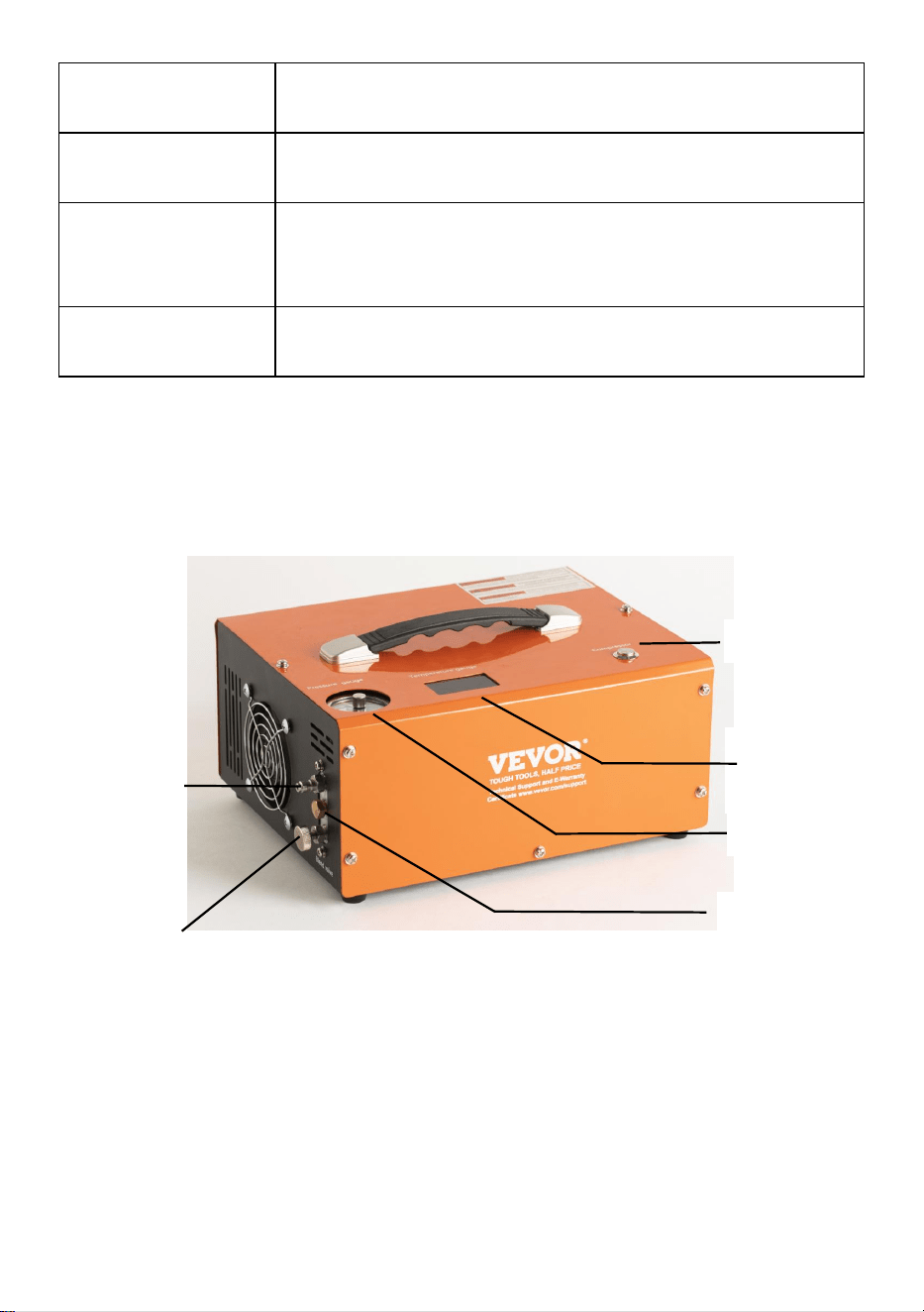
- 5 -
Tryb
zatrzymania
AUTO STOP
System
chłodzenia
Wbudowany wentylator chłodzący
Akcesoria _
przewód zasilający *1, złącze 8mm *1, zestaw części
zamiennych *1, szczypce krokodylkowe*1 Instrukcja
*1
Metoda
chłodzenia
Chłodzony wentylatorem
GŁÓWNE CZĘŚCI OPERACYJNE
Power Switch
Temperature
Display
Pressure gauge
Foster-type
quick-fit air
line
Air line (hose assembly)
bleed screw
Protection Valve
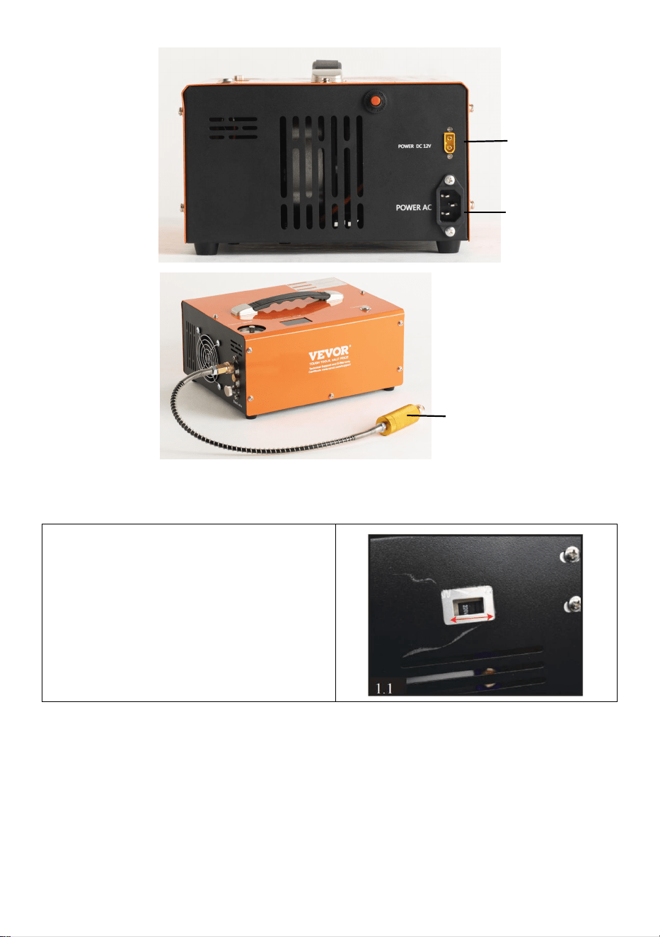
- 6 -
Instrukcje składania
1 . Po pierwsze wszystko, musisz
sprawdzić działanie napięcie,
sprawdzając przycisk na dole
sprężarka.
DC(12V Vehicle
power) cable
socket
AC Power
Socket
Filter System
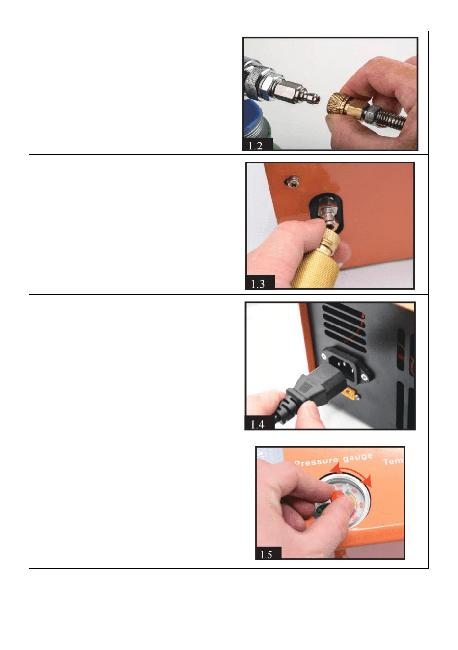
- 7 -
2 . Podłącz szybkozłączkę żeńską
do cylindra wiatrówki , butli z
powietrzem lub Produktyairsoftowe .
3 ) Podłącz kolejny koniec do
gniazda wyjście na _ przód z
kompresor przez A Mężczyzna
dopasowanie . Upewnić się
sprzęgło zastępcze .
4 . Podłącz dostarczony Przewód
zasilający prądu przemiennego po
prawej stronie strona z the główny
jednostka I łączyć wtyczkę
trójbiegunową do gniazdka
sieciowego t .
5 . Ręcznie obracać się the igła z
the automatyczne wyłączanie
system do żądanego ciśnienia .
OSTRZEŻENIE!
NIGDY przepełnić the maksymalny
ciśnienie z swoją butlę i wiatrówkę.
Maksymalne ciśnienie do tego
kompresor wynosi 300 barów (30
Mpa /4500 PSI ).

- 8 -
6. Naciśnij przycisk sprężarki na
górze sprężarki, aby uruchomić
wentylator chłodzący.
UWAGA! Wentylator musi
pracować, gdy pracuje sprężarka .
7 . Zamknąć zawór odpowietrzający
na przód z jednostki głównej,
obracając ją w kierunku zgodnym z
ruchem wskazówek zegara.
Wystarczy, że będzie mocno
zaciśnięty palcem.
8 . Na koniec naciśnij przycisk
ZASILANIE na górze z the główny
jednostka . The kompresor
jednostka będzie zostanie
słyszalnie uruchomiony i
rozpocznie się proces ładowania .
Korzystanie z akumulatora samochodowego DC 12 V
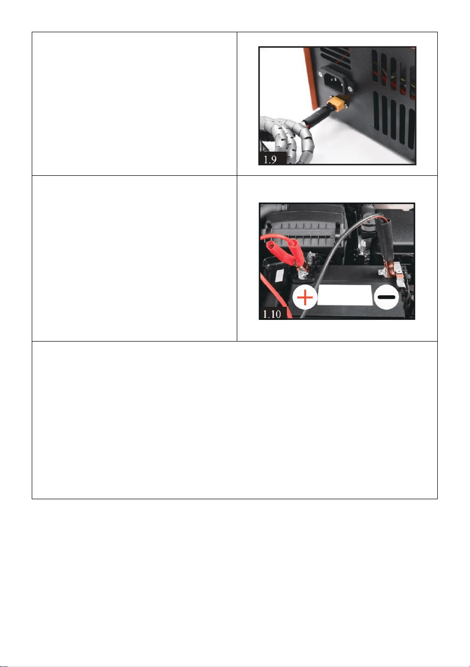
- 9 -
9 . Ubezpiecz samochód silnik
pracuje. Podłącz dostarczony
kabel zasilania prądem stałym do
prawej strony gniazda 12 V.
Podłącz czerwony zacisk na
drugim końcu tego kabla do
dodatniego (+) zacisku samochód
12-woltowy akumulatora.
Następnie podłącz czarny zacisk
do ujemnego (-) bieguna
akumulatora.
Pozostała operacja jest taka sama
jak w kroku 6 na stronie 5
NOTATKA:
Jeśli temperatura robocza przekracza 80 stopni Celsjusza, sprężarkę
MUSISZ wyłączyć ręcznie, możesz nacisnąć przycisk ZASILANIE, aby
sprężarka przestała działać. Pozostaw włączony wentylator chłodzący.
Uruchom ponownie funkcję sprężarki po jej ochłodzeniu.
Sprężarka będzie automatycznie wyłączana co 30 minut, aby zapobiec
przeciążeniu i przegrzaniu. Możesz ponownie uruchomić sprężarkę,
naciskając ponownie przycisk ZASILANIE, jeśli napełnianie powietrzem
nie zostanie zakończone.
Rutynowa konserwacja
Uwaga: sugerujemy konserwację poprzez wymianę pierścieni
uszczelniających i usuwanie brudu co 50 sztuk napełnienia butelki o
pojemności 500 cm3 lub łącznie 20 godzin pracy.
Przed konserwacją upewnij się, że całe zasilanie zostało odłączone!

- 10 -
1 . Poluzuj wszystkie 12 śrub na
szafce. (5 sztuk z przodu, 5 sztuk
z tyłu i 2 sztuki na górze).
Ostrożnie i powoli podnieś całą
metalową szafkę. Uważaj na
przewody wewnętrzne.
2 . Poluzować the przewód
czujnika temperatury przykręcić
cylinder.
3 . Poluzuj 2 śruby po lewej
stronie wyświetlacza.
4 . Poluzuj 2 śruby czerwonego
przewodu dodatniego silnika
(OUT +) i czarnego przewodu
ujemnego (OUT-).

- 11 -
5 . Poluzować 2 śruby rury kondensacyjnej.
6 . Poluzuj 4 śruby silnika na
spodzie sprężarki.
7) Po powyższej operacji
będziesz mieć cały silnik i
cylinder. Następnie poluzuj 2
śruby rurki kondensacyjnej na
cylindrze.

- 12 -
8 . Podobnie jak KROK 5, należy
poluzować mniejszą śrubę na
zewnątrz, a NIE większą.
9 . Poluzuj 2 czarne śruby za
pomocą śrubokręta
sześciokątnego na końcu
tłoczyska.
10 . Poluzuj 4 śruby na górze cylindra. Otrzymasz całą część cylindra.
11 . Zdejmij okrągłą metalową część, oczyść ją z brudu i sprawdź, czy
jakieś pierścienie uszczelniające nie są uszkodzone. Po wyczyszczeniu i
wymianie pierścieni uszczelniających możesz równomiernie nałożyć
odrobinę oleju silikonowego lub oleju silnikowego na wewnętrzny
pierścień uszczelniający .
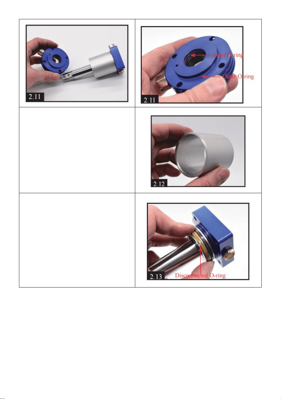
- 13 -
12 . Zdejmij metalową część
kolumny, wyczyść cały brud i
równomiernie nałóż odrobinę
oleju silikonowego lub oleju
silnikowego na wnętrze.
18) Oddzielenie tłoka od
kwadratowej części metalowej.
Wyczyść cały brud i sprawdź jeśli
któryś z pierścieni
uszczelniających jest
uszkodzony.
Odłączenie jasnoszarego
pierścienia O-ring jest
normalnym zjawiskiem.

- 14 -
14) Oczyść brud z wnętrza
kwadratowej części .
15 . Poluzuj śrubę blachy
jednokierunkowej. Oczyść brud,
odłóż arkusz i dokręć śrubę.
WAŻNE: nie dokręcaj śruby zbyt
mocno, ze środka musi wydostać
się powietrze.
16) Poluzuj śrubę jednokierunkową, w środku znajdziesz zawór
jednokierunkowy. Usuń brud i sprawdź, czy sprężyna i zawór nie są
uszkodzone.
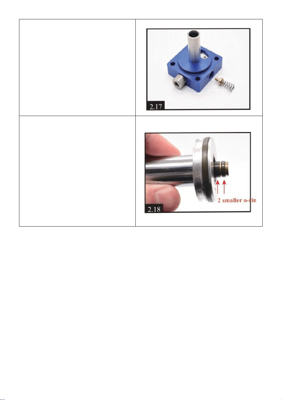
- 15 -
17 . Po wyczyszczeniu załóż
zawór z powrotem. Zwróć
uwagę, że część metalowa jest
skierowana do wewnątrz, a
sprężyna na zewnątrz, jak [2.17].
Dokręć śrubę, którą należy
dokręcić fragment .
18) Sprawdź, czy nie ma
uszkodzeń na pierścieniach
uszczelniających tłoka. Możesz
równomiernie nałożyć trochę
oleju silikonowego lub oleju
silnikowego na 2 mniejsze
o-ringi.
Powyżej znajduje się cała treść
dotycząca konserwacji ! Aby
zmontować go bezproblemowo,
sugerujemy przeglądanie filmu
podczas pracy Film na Youtube -
https://youtu.be/jeKo7dqSfnM
Montaż
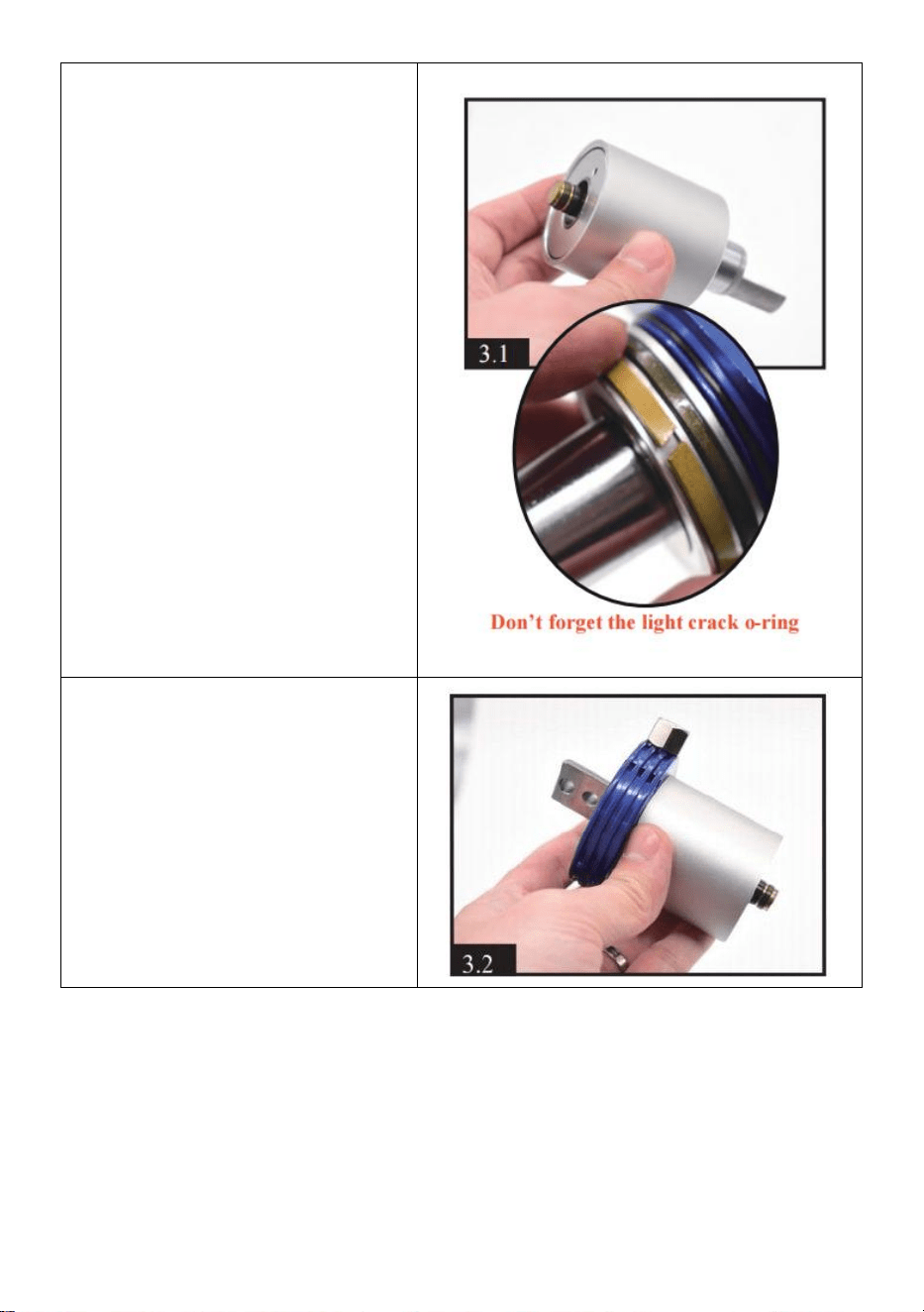
- 16 -
1 . Ustawianie tłoka w
metalowej części kolumny.
Trzymaj dolną część tłoka
równo z częścią kolumny.
2) Umieszczenie okrągłej
części w metalowej części
kolumny.
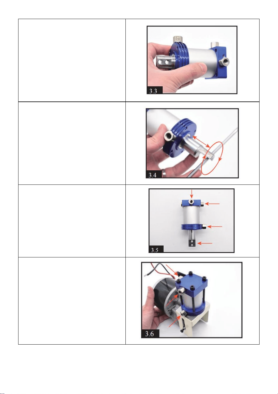
- 17 -
3 . Umieszczenie kwadratowej
części w drugim końcu
okrągłej części. Upewnij się,
że pomiędzy poszczególnymi
częściami nie ma przerw.
4 . Za pomocą narzędzia
przesuwaj tłok w przód i w tył
oraz obracaj go, aby
równomiernie rozprowadzić
olej wewnętrzny. 3-4 razy
będzie w porządku.
5 . Obracając kwadratową,
okrągłą część i tłok, cylinder
wygląda tak samo jak [3.5].
Proszę zwrócić uwagę na
kierunek każdej śruby i
tłoczyska. Wyciągnij tłoczysko
na maksymalną odległość.
6 . Zamontuj cylinder i silnik
razem, dokręć 4 czarne śruby.
Zwróć uwagę na kierunek 3
śrub wskazanych przez
czerwoną strzałkę.
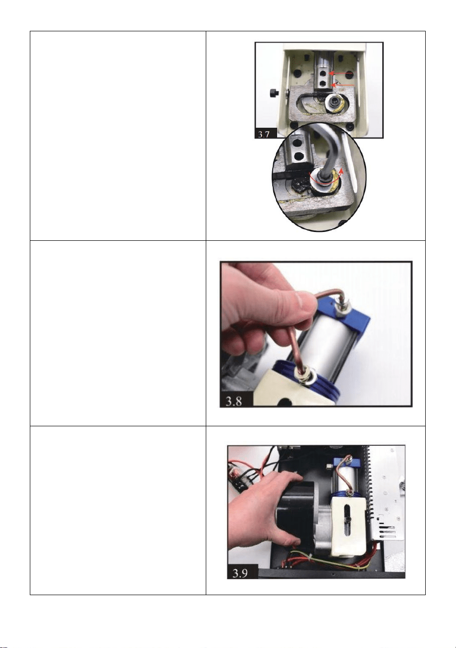
- 18 -
7 . Dokręć 2 czarne śruby na
tłoku drążek i drążek silnika.
Uwaga: położenie można
regulować delikatnie obracając
śrubę silnika za pomocą
śrubokręta sześciokątnego; Co
jest wygodne do montażu 2
czarnych śrub .
8) Zamontować rurkę
kondensacyjną na cylindrze.
9 . Cofanie silnika i cylindra.
Dokręć 4 czarne śruby z
silnikiem na spodzie sprężarki.
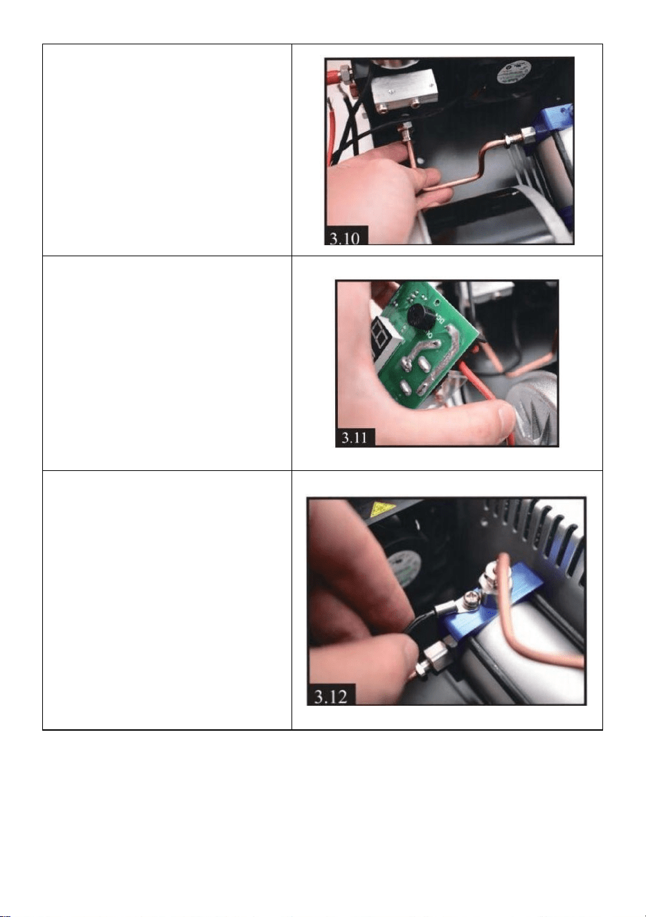
- 19 -
10) Zainstaluj kolejną rurkę
kondensacyjną.
11 . Umieszczenie przewodu
silnika z powrotem na
wyświetlaczu. Czerwony do
OUT+ i czarny do OUT -
12) Odłożenie przewodu
czujnika temperatury na
cylinder.

- 20 -
13) Cofnij wyświetlacz.
Rozwiązywanie problemów
E0- Czujnik temperatury jest uszkodzony .
E1- Automatycznie zatrzymuje się, gdy temperatura przekroczy 85°C .
E2- napięcie jest niższe niż 9,8V .
E3 – Przycisk naciskowy jest uszkodzony .
E4 — Limit czasu pracy i ciśnienie osiągają automatyczne zatrzymanie .


- 2 -
Technisch Ondersteuning en e-garantiecertificaat www.vevor.com/support
PCP-LUCHTCOMPRESSOR
MODEL: SS-PAC02A/SS-PAC02B
We continue to be committed to provide you tools with competitive price.
"Save Half", "Half Price" or any other similar expressions used by us only represents an
estimate of savings you might benefit from buying certain tools with us compared to the major
top brands and does not necessarily mean to cover all categories of tools offered by us. You
are kindly reminded to verify carefully when you are placing an order with us if you are
actually saving half in comparison with the top major brands.

- 1 -
MODEL: SS-PAC02A/SS-PAC02B
Have product questions? Need technical support? Please feel free to
contact us:
Technical Support and E-Warranty Certificate
www.vevor.com/support
NEED HELP? CONTACT US!
This is the original instruction, please read all manual instructions
carefully before operating. VEVOR reserves a clear interpretation of our
user manual. The appearance of the product shall be subject to the
product you received. Please forgive us that we won't inform you again if
there are any technology or software updates on our product.
PCP AIR COMPRESSOR
- 2 -
Waarschuwing-Om het risico op letsel te verminderen, moet
de gebruiker de handleiding zorgvuldig lezen.
CORRECTE VERWIJDERING
Dit product valt onder de bepalingen van de Europese richtlijn
2012/19/EG. Het symbool met een doorgestreepte
afvalcontainer geeft aan dat het product in de Europese Unie
een aparte afvalinzameling vereist. Dit geldt voor het product
en alle accessoires die met dit symbool zijn gemarkeerd.
Producten die als zodanig gemarkeerd zijn, mogen niet met
het normale huisvuil worden weggegooid, maar moeten naar
een inzamelpunt voor recycling van elektrische en
elektronische apparaten worden gebracht
BELANGRIJKE VEILIGHEIDSMAATREGELEN
●Draagbaar PCP Lucht Pistool Compressor kan geopereerd met of _ 220v/110v
AC
( verstelbaar ) stroom , of gelijkstroom 12VVoertuig stroom . Leidt _ voor beide
systemen Zijn geleverd.
●NOOIT begin de Draagbaar compressor zonder Eerst _ hebben
begonnen zijn koeling fan.
●De Draagbaar compressor is ontworpen naar direct vullen lucht geweren
met een integraal cilinder of buddy-fles lucht bron omhoog naar 0,5 liter(50 0
cc ) volume . Het zou moeten niet zijn gebruikt voor vulling duiken tanks
over 500cc. Elk schade naar de compressor of PCP luchtgeweer
veroorzaakt door niet correct operatie of gebruik zullen niet zijn bedekt door
de garantie.
●De Draagbaar compressor heeft A MAXIMUM opladen druk van 300BAR
(4.500 psi /30 MPa ) druk . Echter , veel PCP lucht geweren zullen hebben A
veilig werkend ( bedienend ) druk Dat is lager dan dit - Dus DOEN NIET _
OVERLADEN _ jouw PCP luchtgeweer .

- 3 -
● ALTIJD naleven naar de luchtgeweer fabrikant ' S operationeel
instructies tijdens gebruik de Draagbaar compressor naar aanval jouw
PCP luchtgeweer
●Het is aanbevolen Dat Jij observeren de positie van de naald op de 5s druk
graadmeter van de PCP luchtgeweer En de eenheid druk graadmeter bij
de _ dezelfde tijd tijdens het opladen . Ervoor zorgen Dat de positie doet
niet overschrijden 300 BAR (4500 psi /30 MPa ). Stop blazen lucht
wanneer Het bereikt 280 BAR (3750 psi /28 MPa )
● Naar voorkomen de eenheid oververhitting , altijd bedienen de
compressor in A goed geventileerd ruimte.
● Doen niet demonteren de voornaamst eenheid van de Draagbaar
compressor - daar Zijn geen gebruiker - bruikbaar onderdelen binnen .
Echter , de zeehonden En de filter medium En
filters in de slang montage kan zijn vervangen met de_ reserveonderdelen mits .
●ALTIJD volgen de rudimentair veiligheid procedures _ wanneer opladen
jouw PCP luchtbuks .
● Als het netsnoer beschadigd is, moet het worden vervangen door een
speciaal snoer of een speciaal snoer dat verkrijgbaar is bij de fabrikant of zijn
serviceagent.
● Dit apparaat kan worden gebruikt door kinderen van 8 jaar en ouder en
door personen met verminderde lichamelijke, zintuiglijke of geestelijke
vermogens of een gebrek aan ervaring en kennis, als zij onder toezicht staan
of instructies hebben gekregen over het veilige gebruik van het apparaat en
de gevaren die ermee gepaard gaan. Kinderen mogen niet met het apparaat
spelen. Reiniging en gebruikersonderhoud mogen niet door kinderen zonder
toezicht worden uitgevoerd.
BEWAAR DEZE INSTRUCTIES
FCC-informatie
VOORZICHTIGHEID:
Wijzigingen of aanpassingen die niet uitdrukkelijk zijn goedgekeurd door
de partij die verantwoordelijk is voor naleving kunnen de bevoegdheid van
de gebruiker om de apparatuur te bedienen ongeldig maken!
Dit apparaat voldoet aan Deel 15 van de FCC-regels. De werking is
onderworpen aan de volgende twee voorwaarden:

- 4 -
1) Dit product kan schadelijke interferentie veroorzaken.
2)Dit product moet alle ontvangen interferentie accepteren, inclusief
interferentie die een ongewenste werking kan veroorzaken.
WAARSCHUWING:
Wijzigingen of aanpassingen aan dit product die niet uitdrukkelijk zijn
goedgekeurd door de partij die verantwoordelijk is voor naleving kunnen de
bevoegdheid van de gebruiker om het product te bedienen ongeldig
maken.
Opmerking:
Dit product is getest en voldoet aan de limieten voor een digitaal apparaat
van Klasse B overeenkomstig Deel 15 van de FCC-regels. Deze limieten
zijn bedoeld om redelijke bescherming te bieden tegen schadelijke
interferentie in een residentiële installatie.
Dit product genereert, gebruikt en kan radiofrequentie-energie uitstralen,
en als het niet wordt geïnstalleerd en gebruikt in overeenstemming met de
instructies, kan het schadelijke interferentie aan radiocommunicatie
veroorzaken. Er is echter geen garantie dat er geen interferentie zal
optreden in een bepaalde installatie. Als dit product schadelijke
interferentie veroorzaakt aan radio- of televisieontvangst, wat kan worden
vastgesteld door het product uit en weer in te schakelen, wordt de
gebruiker aangeraden te proberen de interferentie te corrigeren door een
of meer van de volgende maatregelen.
· Heroriënteer of verplaats de ontvangstantenne.
· Vergroot de afstand tussen het product en de ontvanger.
· Sluit het product aan op een stopcontact op een ander circuit dan dat
waarop de ontvanger is aangesloten.
· Raadpleeg de dealer of een ervaren radio-/tv-technicus voor hulp.
Productparameters
Model
SS-PAC02A/SS-PAC02B
Spanning:
DC 12V voor autoaccu of AC 120V/230V
Stroom
300W
Inflatie druk
4500 psi / 30 MPa
Stopmodus
AUTO STOP
Koelsysteem
Ingebouwde ventilatorkoeling
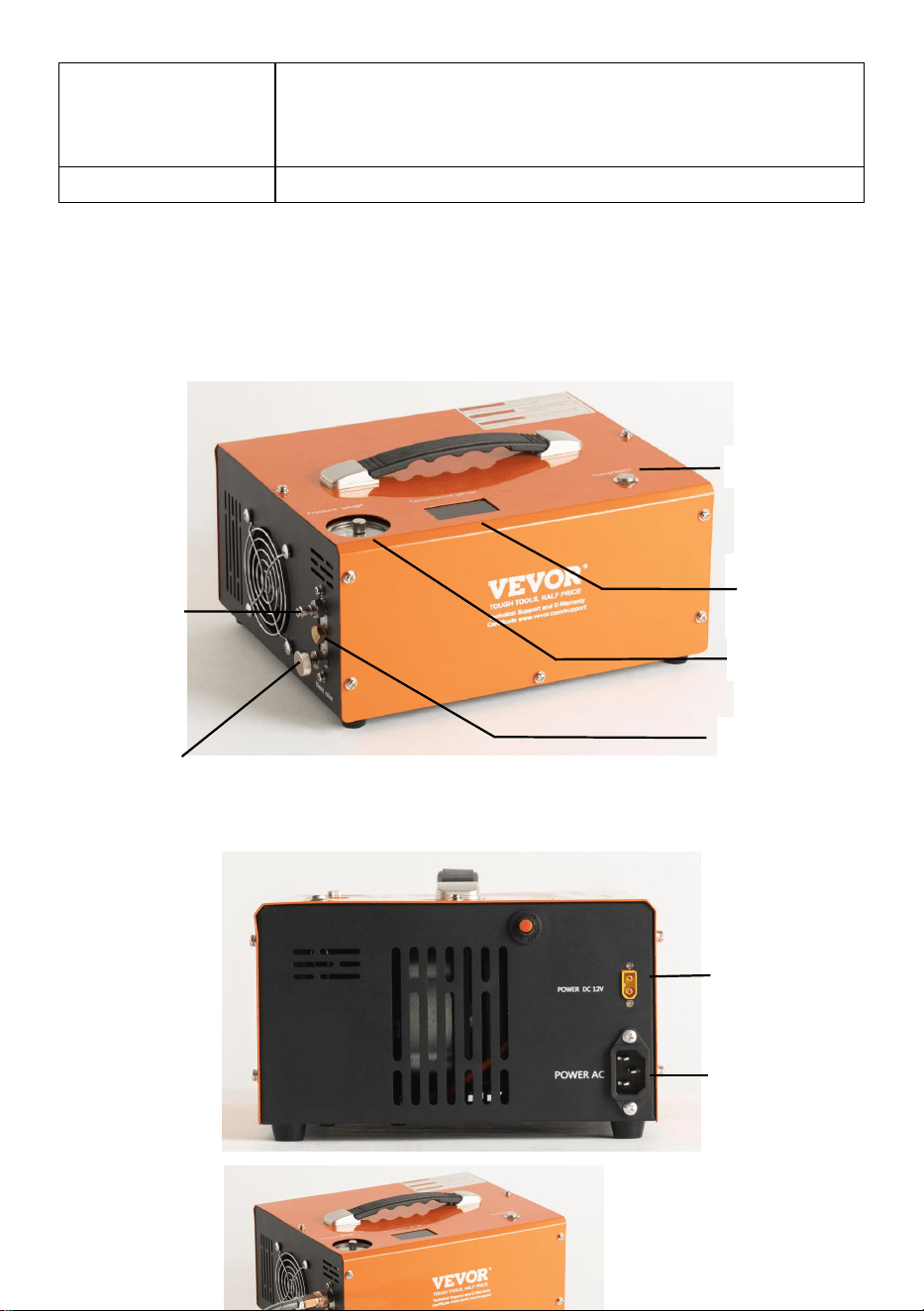
- 5 -
Een accessoires
netsnoer *1, 8 mm connector *1, pak met
reserveonderdelen *1, krokodillentang*1 Handleiding
*1
Koelmethode
Ventilator gekoeld
BELANGRIJKSTE BEDIENINGSONDERDELEN
Power Switch
Temperature
Display
Pressure gauge
Foster-type
quick-fit air
line
Air line (hose assembly)
bleed screw
Protection Valve
DC(12V Vehicle
power) cable
socket
AC Power
Socket
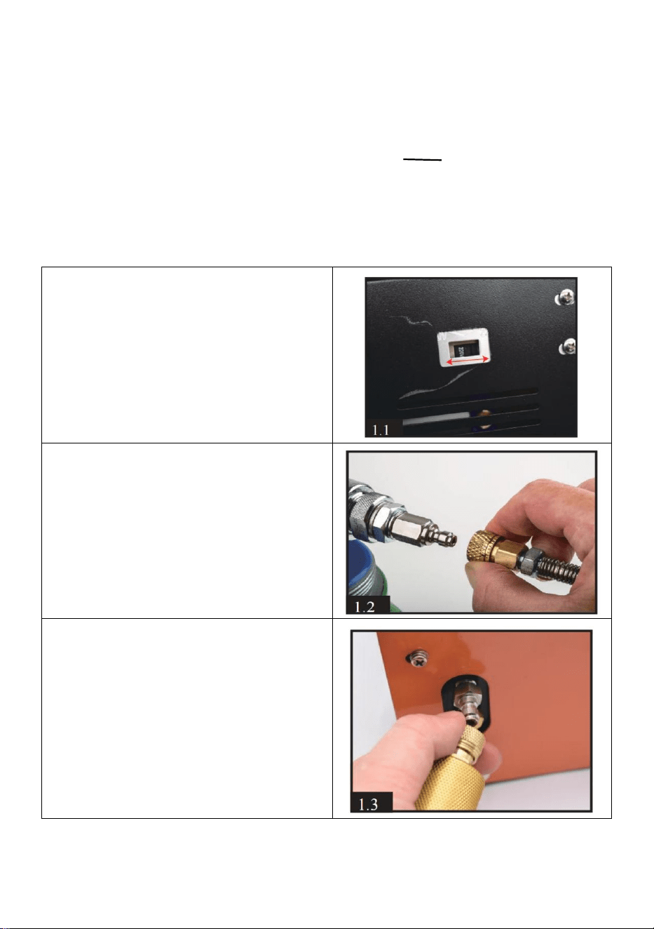
- 6 -
Montage-instructies
1 . Eerste van alles, je moet de
werking inspecteren spanning door
het controleren van de knop aan de
onderkant van de compressor.
2 . Sluit de vrouwelijke
snelkoppeling aan op uw
luchtbukscilinder , luchtfles of Airsoft
-producten.
3 ) Sluit een ander eindkostuum
aan op de uitgang op de voorkant
van compressor via A mannelijk
passend . Zorg ervoor dat de
pleegkoppeling .
Filter System
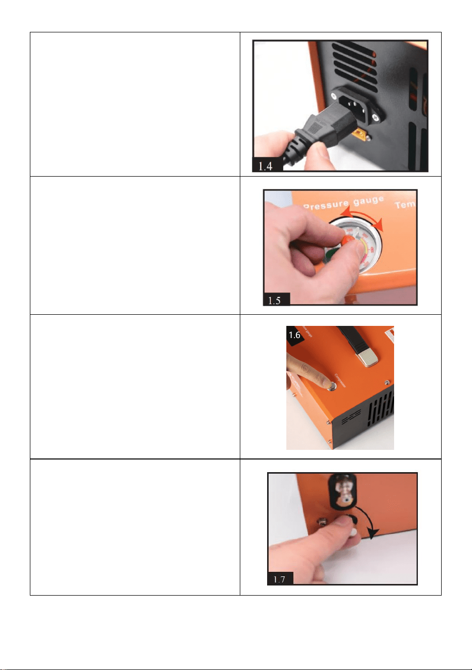
- 7 -
4 . Sluit de meegeleverde aan
Netsnoer naar rechts _ kant van de
voornaamst eenheid En aansluiten
de driepolige stekker in het
stopcontact t .
5 . Handmatig draaien de naald van
de automatische uitschakeling
systeem op de gewenste druk.
WAARSCHUWING!
NOOIT overvullen de maximaal
druk van uw cilinder en luchtbuks.
De maximale druk hiervoor
compressor bedraagt 300 bar (30
MPa /4500 PSI ).
6. Druk op de Compressor-knop
bovenop de compressor om de
koelventilator te starten.
AANDACHT! De ventilator moet
draaien als de compressor werkt .
7 . Sluit het ontluchtingsventiel op
de voorkant van de hoofdeenheid
door deze met de klok mee te
draaien. Het hoeft alleen maar
vingervast te zijn.

- 8 -
8 . Druk ten slotte op de
POWER-knop bovenaan van de
voornaamst eenheid . De
compressor eenheid zullen
hoorbaar op en het laadproces
begint .
Gebruik van DC 12V auto-accuvoeding
9 . Verzeker de auto de motor
draait. Sluit de meegeleverde
gelijkstroomkabel aan op de
rechterkant van de
12V-aansluiting.
Sluit de rode clip aan het andere
uiteinde van deze kabel aan op de
positieve (+) aansluiting van de
auto 12 volt batterij. Sluit
vervolgens de zwarte clip aan op
de negatieve (-) pool van de
batterij.
De resthandeling is hetzelfde als
stap 6 op pagina 5
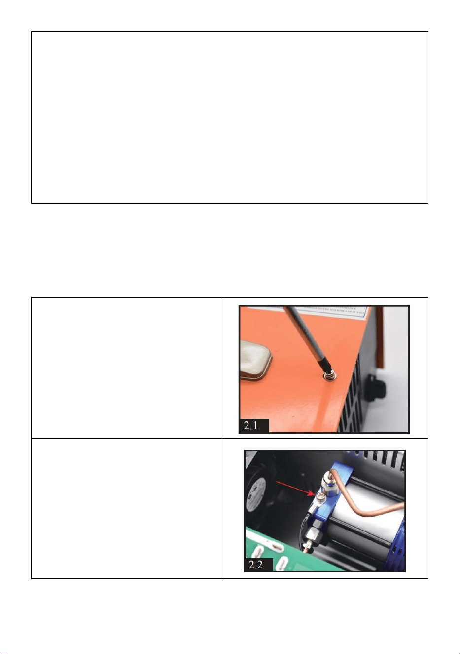
- 9 -
OPMERKING:
Als de werktemperatuur hoger is dan 80 graden Celsius, MOET de
compressor handmatig worden uitgeschakeld. U kunt op de
POWER-knop drukken om de compressor te laten stoppen met werken.
Laat de koelventilator draaien. Start de compressorfunctie opnieuw
zodra de compressor is afgekoeld.
De compressor wordt elke 30 minuten automatisch uitgeschakeld om
overbelasting en oververhitting te voorkomen. U kunt de compressor
opnieuw opstarten door nogmaals op de POWER-knop te drukken als
het luchtvullen niet is voltooid.
Gepland onderhoud
Opmerking: wij raden u aan onderhoud uit te voeren door de O-ringen te
vervangen en vuil te verwijderen elke 50 stuks 500cc flesvulling of een
cumulatieve werking van 20 uur.
Zorg ervoor dat alle stroom is uitgeschakeld vóór onderhoud!
1 . Draai alle 12 stuks schroeven
op de kast los. (5 stuks aan
voorzijde, 5 stuks aan de
achterkant en 2 stuks aan de
bovenkant). Pak de hele metalen
kast voorzichtig en langzaam op.
Wees voorzichtig met de interne
draden.
2 . Losmaken de draad
temperatuursensor schroef de
cilinder vast.
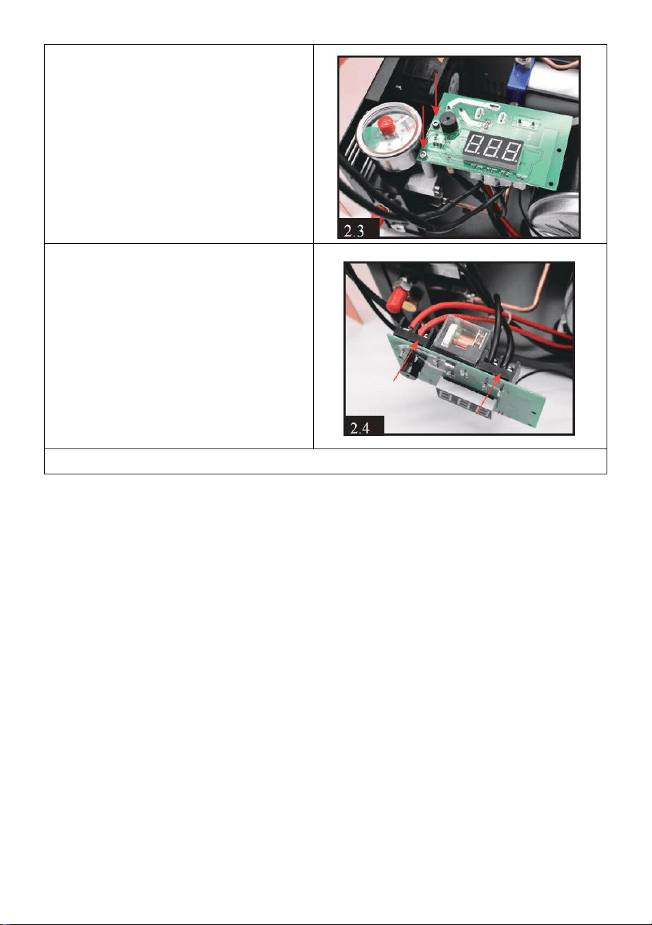
- 10 -
3 . Draai de twee schroeven aan
de linkerkant van het display los.
4 . Maak de twee schroeven van
de rode positieve draad (OUT +)
en de zwarte negatieve draad
(OUT-) van de motor los.
5 . Losmaken de 2 stuks schroeven van de condensatiebuis.

- 11 -
6 . Draai de 4 motorschroeven
aan de onderkant van de
compressor los.
7) Na bovenstaande handeling
beschikt u over de hele motor en
cilinder. Draai vervolgens de 2
stuks schroeven van de
condensbuis op de cilinder los.

- 12 -
8 . Hetzelfde als STAP 5, moet u
de kleinere schroef aan de
buitenkant losdraaien, NIET de
grotere.
9 . Draai de twee zwarte
schroeven los met behulp van
een zeskantschroevendraaier
aan het uiteinde van de
zuigerstang.
10 . Draai de 4 stuks schroeven aan de bovenkant van de cilinder los. Je
hebt het hele cilindergedeelte.
11 . Verwijder het ronde metalen onderdeel, verwijder al het vuil en
controleer of er O-ringen beschadigd zijn. Na het reinigen en vervangen
van de O-ringen kunt u gelijkmatig wat siliconenolie of motorolie op de
binnenste O-ring aanbrengen .

- 13 -
12 . Verwijder het metalen deel
van de kolom, verwijder al het
vuil en breng gelijkmatig wat
siliconenolie of motorolie aan de
binnenkant.
19) Het scheiden van de zuiger
en het vierkante metalen deel.
Verwijder al het vuil en controleer
als er O-ringen beschadigd zijn.
Het is normaal als u merkt dat de
lichtgrijze O-ring los zit.
vierkante gedeelte opruimen .

- 14 -
15 . Draai de schroef van
eenrichtingsmetaalplaat los.
Reinig vuil, plaats het laken terug
en draai de schroef vast.
BELANGRIJK: draai de schroef
niet te vast, er moet lucht van
binnenuit komen.
16) Draai de eenrichtingsschroef los. Binnenin bevindt zich een
eenrichtingsklep. Verwijder het vuil en controleer of er schade is aan de
veer en het ventiel.
17 . Na het reinigen de klep
terugplaatsen. Let op: het
metalen onderdeel is naar binnen
gericht en de veer is naar buiten
gericht, zoals [2.17]. Draai de
schroef vast, die moet worden
vastgedraaid. beetje .

- 15 -
18) Controleer of er schade is
aan de O-ringen van de zuiger.
Op 2 kleinere o-ringen kun je
gelijkmatig wat siliconenolie of
motorolie aanbrengen.
Hierboven vindt u alle
onderhoudsinhoud ! Om het
apparaat soepel weer in elkaar te
zetten, raden wij u aan tijdens het
gebruik door de video te bladeren
Video via Youtube
-https://youtu.be/jeKo7dqSfnM
Montage
1 . Het plaatsen van de zuiger
in het metalen onderdeel van
de kolom. Houd de onderkant
van de zuiger gelijk met het
kolomgedeelte.

- 16 -
2) Plaats het ronde vormdeel
in het metalen kolomdeel.
3 . Plaats het vierkante deel in
een ander uiteinde van het
ronde deel. Zorg ervoor dat er
geen openingen tussen de
onderdelen zitten.
4 . Gebruik een gereedschap
om de zuiger heen en weer te
bewegen en te draaien om de
interne olie gelijkmatig te
verdelen. 3-4 keer is prima.
5 . Door het vierkante, ronde
deel en de zuiger te draaien,
ziet de cilinder er hetzelfde uit
als [3.5]. Let op de richting van
elke schroef en zuigerstang.
Trek de zuigerstangafstand tot
het langste.
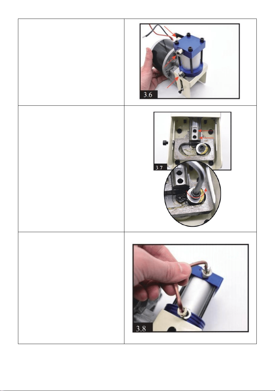
- 17 -
6 . Installeer de cilinder en de
motor samen, draai de 4
zwarte schroeven vast.
Let op de richting van de 3
schroeven van de rode pijl.
7 . Draai de 2 zwarte
schroeven op de zuiger vast
stang en motorstang.
Opmerking: u kunt de positie
aanpassen door de
motorschroef voorzichtig te
draaien met een zeshoekige
schroevendraaier; wat handig
is voor de installatie van 2
zwarte schroeven .
8) Installeer de
condensatiebuis op de cilinder.

- 18 -
9 . Het terugzetten van de
motor en cilinder. Draai de 4
zwarte schroeven met motor
aan de onderkant van de
compressor vast.
10) Installeer nog een
condensatiebuis.
11 . Plaats de motordraad
terug in het display. Rood naar
OUT+ en zwart naar OUT -
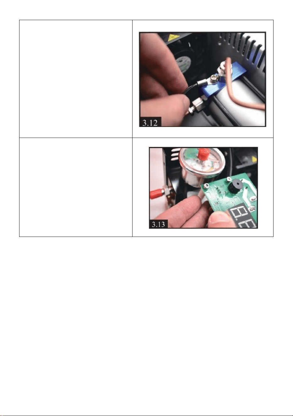
- 19 -
12) Plaats de draad van de
temperatuursensor terug op de
cilinder.
13) Het display terugzetten.
Probleemoplossen
E0- De temperatuursensor is defect .
E1- Stopt automatisch wanneer de temperatuur hoger is dan 85 ° C.
- spanning is lager dan 9,8 V.
E3- De drukknop is defect .
E4-Werktijdlimiet en druk bereiken automatische stop .


- 2 -
Teknisk Support och e-garanticertifikat www.vevor.com/support
PCP LUFTKOMPRESSOR
MODELL: SS-PAC02A/SS-PAC02B
We continue to be committed to provide you tools with competitive price.
"Save Half", "Half Price" or any other similar expressions used by us only represents an
estimate of savings you might benefit from buying certain tools with us compared to the major
top brands and does not necessarily mean to cover all categories of tools offered by us. You
are kindly reminded to verify carefully when you are placing an order with us if you are
actually saving half in comparison with the top major brands.

- 1 -
MODELL: SS-PAC02A/SS-PAC02B
Have product questions? Need technical support? Please feel free to
contact us:
Technical Support and E-Warranty Certificate
www.vevor.com/support
NEED HELP? CONTACT US!
This is the original instruction, please read all manual instructions
carefully before operating. VEVOR reserves a clear interpretation of our
user manual. The appearance of the product shall be subject to the
product you received. Please forgive us that we won't inform you again if
there are any technology or software updates on our product.
PCP AIR COMPRESSOR

- 2 -
Varning - För att minska risken för skada måste användaren
läsa instruktionerna noggrant.
KORREKT AVFALLSHANTERING
Denna produkt omfattas av bestämmelserna i det europeiska
direktivet 2012/19/EC. Symbolen som visar en soptunna
korsad anger att produkten kräver separat sophämtning i EU.
Detta gäller för produkten och alla tillbehör märkta med denna
symbol. Produkter märkta som sådana får inte slängas
tillsammans med vanligt hushållsavfall, utan måste lämnas till
en insamlingsplats för återvinning av elektriska och
elektroniska apparater
VIKTIGA SÄKERHETSÅTGÄRDER
●Bärbar PCP Luft Pistol Kompressor burk opererades med eller henne 220v/110v
AC
( justerbar) kraft , eller DC 12VFordon kraft . Le annonser för både system är
levereras.
●ALDRIG Start de Bärbar kompressor utan först _ har satte igång dess
kyl- fläkt.
●De Bärbar kompressor är designad till direkt fylla luftgu ns med en
väsentlig cylinder eller kompis-flaska luft källa upp till 0,5 liter (50 0 cc ) volym
. Det skall inte vara Begagnade för fyllning scuba tankar över 500cc.
Några skada till de kompressor eller PCP luftpistol orsakade genom felaktig
drift eller använda sig av kommer inte vara täckt förbi de garanti.
●De Bärbar kompressor har a MAXIMAL laddning tryck av 300BAR (4 500 psi
/30 MPa ) tryck . Dock , många PCP luftgevär kommer ha a säker arbetar ( dri
ft ) tryck den där är lägre än detta - Så DO NEJ T ÖVER -LADDA din PCP
luftpistol .
● ALLTID ansluta sig till de luftpistol tillverkare ' s fungerar instruktioner
när man använder de Bärbar kompressor till avgift din PCP luftpistol

- 3 -
●Det är rekommenderad den där du observera de placera av de nål på de 5s
tryck mätare av de PCP luftpistol och de enhet tryck mätare på den e
samma tid under laddning . Säkerställa den där de placera gör inte
överstiga 300 BAR (4500 psi /30 MPa ). Sluta blåser luft när Det når
280 BAR (3750 psi /28 MPa )
● Till undvika de enhet överhettning , alltid fungera de kompressor i a
väl ventilerad Plats.
● Do inte plocka isär de huvud enhet av de Bärbar kompressor - där är
ingen användare - servicebar delar inuti . Dock , de tätningar och de
filtrera medium och
filter i de slang hopsättning burk vara ersatt med den e reservdelar försedd .
●ALLTID Följ de rudimentär säkerhet pr förfaranden när laddning din PCP
luftgevär .
● Om nätsladden är skadad måste den bytas ut mot en speciell sladd eller
enhet som finns tillgänglig från tillverkaren eller dess servicerepresentant.
● Denna apparat kan användas av barn från 8 år och uppåt och personer
med nedsatt fysisk, sensorisk eller mental förmåga eller brist på erfarenhet
och kunskap om de har fått övervakning eller instruktioner om hur man
använder apparaten på ett säkert sätt och förstår inblandade faror. Barn får
inte leka med apparaten. Rengöring och användarunderhåll får inte utföras
av barn utan tillsyn.
SPARA DESSA INSTRUKTIONER
FCC-information
VARNING:
Ändringar eller modifieringar som inte uttryckligen godkänts av den part
som ansvarar för överensstämmelse kan ogiltigförklara användarens
behörighet att använda utrustningen!
Denna enhet uppfyller del 15 av FCC-reglerna. Driften är föremål för
följande två villkor:
1) Denna produkt kan orsaka skadliga störningar.
2) Denna produkt måste acceptera alla mottagna störningar, inklusive
störningar som kan orsaka oönskad funktion.
VARNING:

- 4 -
Ändringar eller modifieringar av denna produkt som inte uttryckligen
godkänts av den part som är ansvarig för efterlevnaden kan upphäva
användarens behörighet att använda produkten.
Notera:
Denna produkt har testats och befunnits överensstämma med gränserna
för en digital enhet av klass B i enlighet med del 15 av FCC-reglerna.
Dessa gränser är utformade för att ge rimligt skydd mot skadlig störning i
en bostadsinstallation.
Denna produkt genererar, använder och kan utstråla radiofrekvensenergi,
och om den inte installeras och används i enlighet med instruktionerna kan
den orsaka skadliga störningar på radiokommunikation. Det finns dock
ingen garanti för att störningar inte kommer att inträffa i en viss installation.
Om denna produkt orsakar skadliga störningar på radio- eller
tv-mottagning, vilket kan fastställas genom att stänga av och på produkten,
uppmanas användaren att försöka korrigera störningen med en eller flera
av följande åtgärder.
· Rikta om eller flytta mottagningsantennen.
· Öka avståndet mellan produkten och mottagaren.
· Anslut produkten till ett uttag på en annan krets än den som mottagaren
är ansluten till.
· Kontakta återförsäljaren eller en erfaren radio/TV-tekniker för hjälp.
Produktparametrar
Modell
SS-PAC02A/SS-PAC02B
Spänning:
DC 12V för bilbatteri eller AC 120V/230V
Kraft
300W
Uppblåsningstryck
4500Psi / 30Mpa
Stoppläge
AUTOMATISKT STOPP
Kylsystem
Inbyggd fläktkylning
Tillbehör _
nätsladd *1, 8 mm kontakt *1, reservdelsdräkt *1,
krokodiltänger*1 manuell *1
Kylningsmetod
Fläktkyld
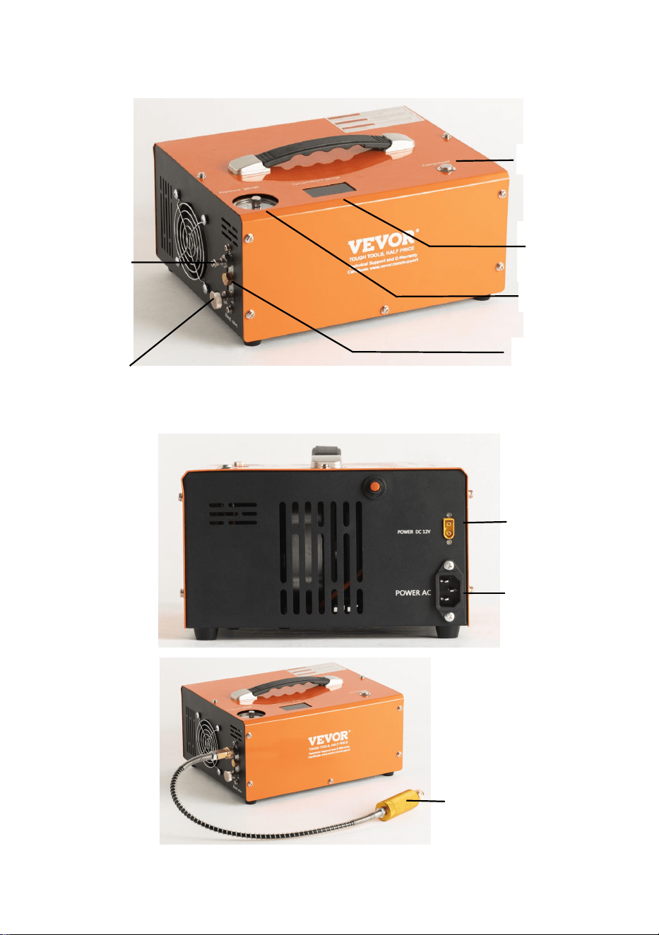
- 5 -
HUVUDDRIFTANDE DELAR
Power Switch
Temperature
Display
Pressure gauge
Foster-type
quick-fit air
line
Air line (hose assembly)
bleed screw
Protection Valve
DC(12V Vehicle
power) cable
socket
AC Power
Socket
Filter System

- 6 -
Monteringsanvisningar
1 . Först av allt, du måste inspektera
hur det fungerar spänning genom att
kontrollera knappen på undersidan
av kompressorn.
2 . Anslut snabbkopplingen till din
Airgun cylinder , Air Bottle eller
Airsoft produkter.
3 ) Anslut en annan ändfoster till
produktion på _ främre av
kompressor via a manlig passande .
Se till fosterparet .
4 . Anslut den medföljande Nätsladd
till höger - hand sida av de huvud
enhet och ansluta den trepoliga
kontakten till eluttaget t .
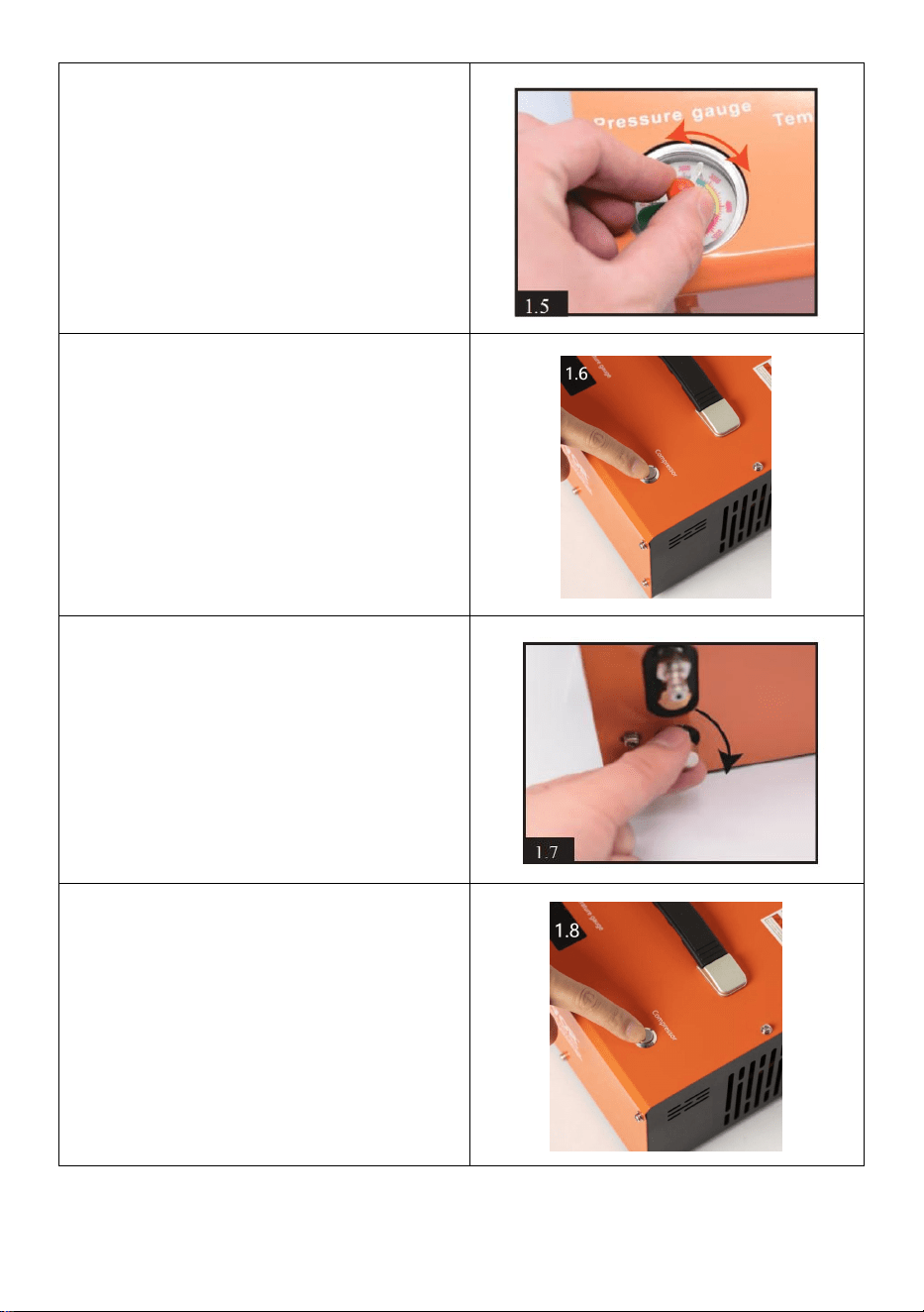
- 7 -
5 . Manuellt rotera de nål av de
automatisk avstängning systemet till
det tryck du vill ha.
VARNING!
ALDRIG överfyllning de maximal
tryck av din cylinder och luftgevär.
Maximalt tryck för detta kompressor
är 300 bar (30 Mpa /4500 PSI ).
6. Tryck på knappen Kompressor på
toppen av kompressorn för att starta
kylfläkten.
UPPMÄRKSAMHET! Fläkten måste
vara igång när kompressorn är
igång .
7 . Stäng avluftningsventilen på
främre av huvudenheten genom att
vrida den medurs. Det behöver bara
vara fingertight.
8 . Slutligen trycker du på
POWER-knappen på toppen av de
huvud enhet . De kompressor
enhet kommer startar hörbart och
laddningsprocessen börjar .

- 8 -
Använder DC 12V bilbatteri
9 . Försäkra bilen motorn är igång.
Anslut den medföljande
likströmskabeln till höger sida av
12v-uttaget.
Anslut den röda klämman i andra
änden av denna kabel till den
positiva (+) polen på bilens 12 volt
batteri. Anslut sedan den svarta
klämman till batteriets minuspol (-).
Åtgärden är densamma som steg
6 på sidan 5
NOTERA:
Om arbetstemperaturen överstiger 80 grader Celsius MÅSTE
kompressorn stängas av manuellt, du kan trycka på POWER-knappen
för att få kompressorn att sluta fungera. Låt kylfläkten vara kvar igång.
Starta om kompressorfunktionen när kompressorn har svalnat.
Kompressorn stängs av automatiskt var 30:e minut för att förhindra
överbelastning och överhettning. Du kan starta om kompressorn genom
att trycka på POWER-knappen igen om luftfyllningen inte är klar.
Rutin underhållning
Obs: vi föreslår att du kan utföra underhåll genom att byta o-ringar och
rensa bort smuts var 50:e stycke 500cc flaska fyllning eller kumulativt
arbete 20 timmar.
Se till att all ström är frånkopplad innan underhåll!

- 9 -
1 . Lossa alla 12 delar av skruven
på skåpet. (5 stycken på
framsidan, 5 stycken på baksidan
och 2 stycken på toppen). Plocka
upp hela metallskåpet försiktigt
och långsamt. Var försiktig med
de interna ledningarna.
2 . Lossa de
temperatursensorkabel skruva
på cylindern.
3 . Lossa de två skruvarna till
vänster på displayen.
4 . Lossa de två skruvarna på
motorns röda positiva tråd (OUT
+) och svarta negativa tråden
(OUT-).

- 10 -
5 . Lossa de 2 delade skruvarna av kondensröret.
6 . Lossa de 4 delade
motorskruvarna på botten av
kompressorn.
7) Du kommer att ha hela motorn
och cylindern efter ovanstående
operation. Lossa sedan de två
skruvarna av kondensröret på
cylindern.
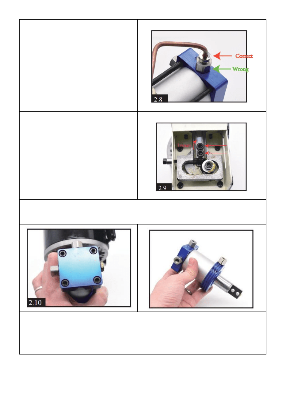
- 11 -
8 . Samma som STEG 5, måste
lossa den mindre skruven nära
utsidan, INTE den större.
9 . Lossa de två svarta skruvarna
med en sexkantskruvmejsel på
änden av kolvstången.
10 . Lossa de 4 delade skruvarna på cylindertoppen. Du kommer att ha
hela cylinderdelen.
11 . Ta av den runda metalldelen, rengör all smuts och kontrollera om
några o-ringar är skadade. Efter rengöring och byte av o-ringar kan du
applicera lite silikonolja eller motorolja jämnt på den inre o-ringen .

- 12 -
12 . Ta av pelarens metalldel,
rengör all smuts och applicera
jämnt lite silikonolja eller
motorolja på insidan.
20) Separerar kolven och den
fyrkantiga metalldelen. Rengör all
smuts och kontrollera om några
o-ringar är skadade.
Det är normalt om du hittar den
ljusgrå O-ringen frånkopplad.
14) Rensa upp smutsen inuti
kvadraten .

- 13 -
15 . Lossa skruven på
envägsmetallplåt. Rengör smuts,
sätt tillbaka plåten och dra åt
skruven.
VIKTIGT: dra inte åt skruven för
hårt, luft måste komma ut inifrån.
16) Lossa envägsskruven, du hittar en envägsventil inuti. Rensa upp
smutsen och kontrollera om det finns några skador på fjäder och ventil.
17 . Efter rengöring, sätt tillbaka
ventilen. Observera att
metalldelen är vänd inåt och att
fjädern är vänd utåt som [2.17].
Dra åt skruven som måste dras
åt en lite .
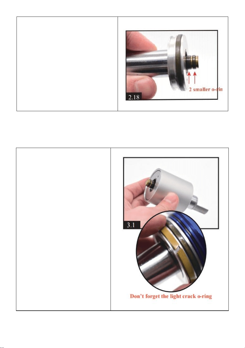
- 14 -
18) Kontrollera om det finns
några skador på kolvens o-ringar.
Du kan applicera lite silikonolja
eller motorolja jämnt på 2 mindre
o-ringar.
Ovanför allt underhållsinnehåll !
För att montera tillbaka den
smidigt föreslår vi att du kan
bläddra i videon medan du
använder den Video via Youtube
-https://youtu.be/jeKo7dqSfnM
hopsättning
1 . Inställning av kolven i
pelarens metalldel. Håll
kolvens botten jämn med
pelardelen.

- 15 -
2) Inställning av den runda
delen i pelarens metalldel.
3 . Placera den fyrkantiga
delen i en annan ände av den
runda delen. Se till att det inte
finns några mellanrum mellan
varje del.
4 . Använd ett verktyg för att
flytta kolven fram och tillbaka
och rotera för att få den inre
oljan jämnt spridd. 3-4 gånger
kommer att vara bra.
5 . Genom att vrida en
fyrkantig, rund del och kolv får
cylindern att se likadan ut som
[3,5]. Observera riktningen för
varje skruv och kolvstång. Dra
kolvstångsavståndet till det
längsta.

- 16 -
6 . Montera cylindern och
motorn tillsammans, dra åt 4
svarta skruvar.
Var uppmärksam på riktningen
för de 3 skruvarna på den röda
pilen.
7 . Dra åt de 2 svarta
skruvarna på kolven spö och
motorstång.
Obs: du kan justera positionen
genom att försiktigt rotera
motorskruven med en
sexkantskruvmejsel; vilket är
bekvämt för montering av 2
svarta skruvar .
8) Montera kondensröret på
cylindern.

- 17 -
9 . Sätta tillbaka motor och
cylinder. Dra åt 4 svarta
skruvar med motor på
undersidan av kompressorn.
10) Installera ytterligare ett
kondensrör.
11 . Sätta tillbaka motorkabeln
i displayen. Röd till OUT+ och
svart till OUT -
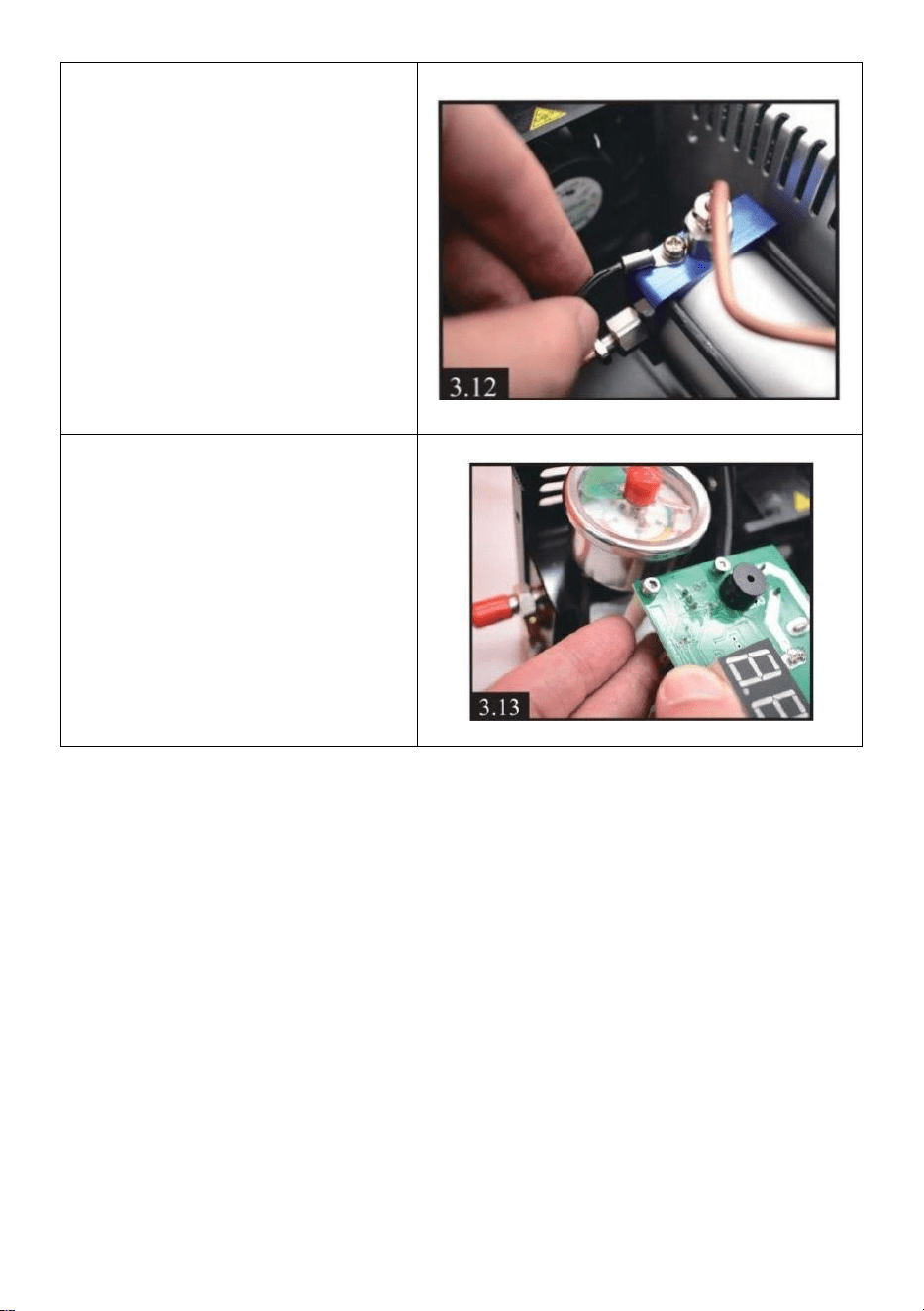
- 18 -
12) Sätta tillbaka
temperaturgivarens tråd på
cylindern.
13) Ställa tillbaka displayen.
Felsökning
E0- Temperatursensorn är defekt .
E1- Stoppar automatiskt när temperaturen överstiger 85 °C .
E2-spänningen är lägre än 9,8V .
E3- Tryckknappen är defekt .
E4-Arbetstidsgräns och tryck når automatiskt stopp .

