
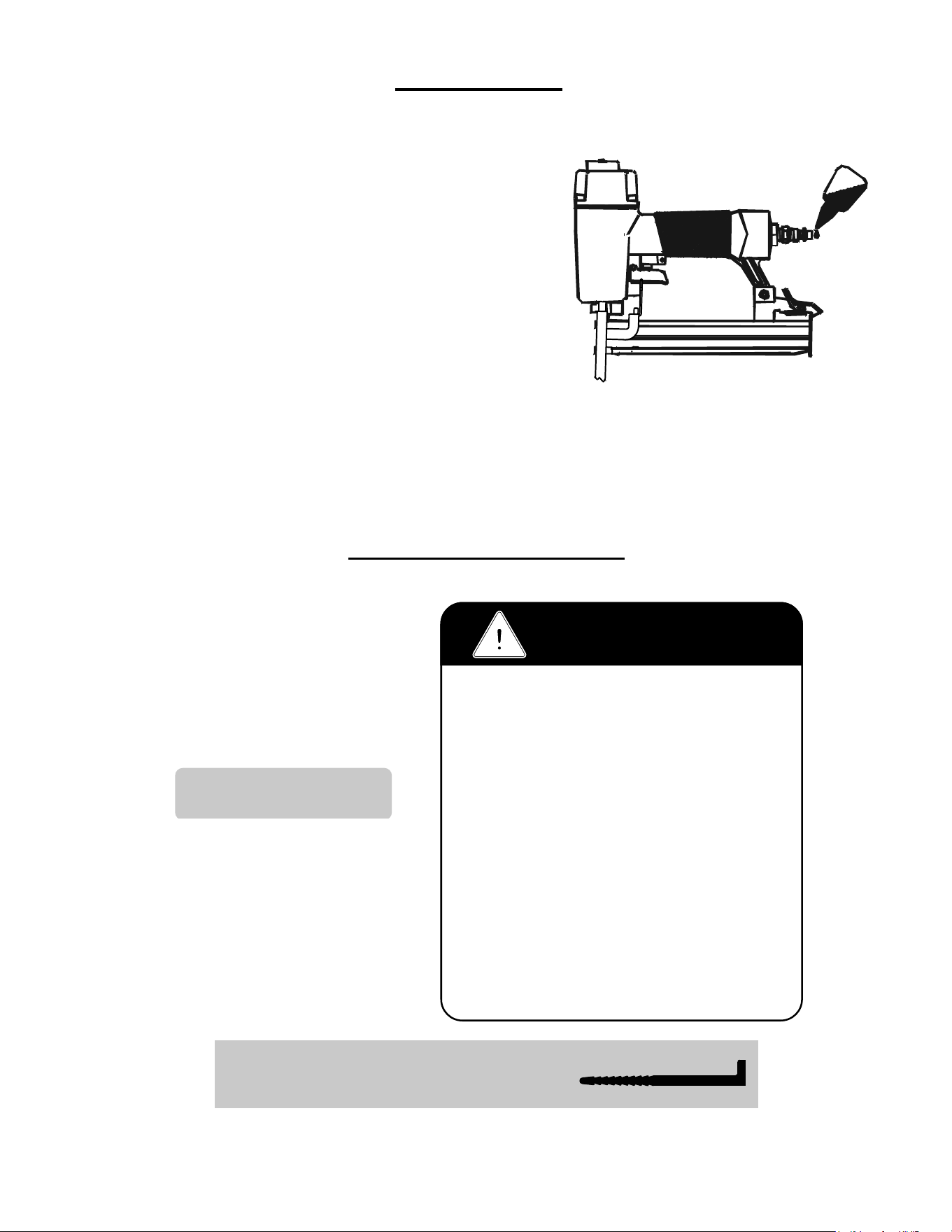
Model 2000TN Pneumatic Top Nailer™
POWERNAIL
®
CO.
REV 2024.04.25
WARNING
OPERATION AND MAINTENANCE MANUAL
MANUAL DE OPERACION Y DE MANTENIMIENTO
MANUEL D’INSTRUCTIONS ET D’ENTRETIEN
Read this manual before you use this Powernailer®. Follow all safety warnings and
instructions. If you are uncertain about the operation of the nailer, call us directly
at 1-800-323-1653 for assistance or contact the closest Powernail Dealer for help.
Please retain this information for future reference.

2
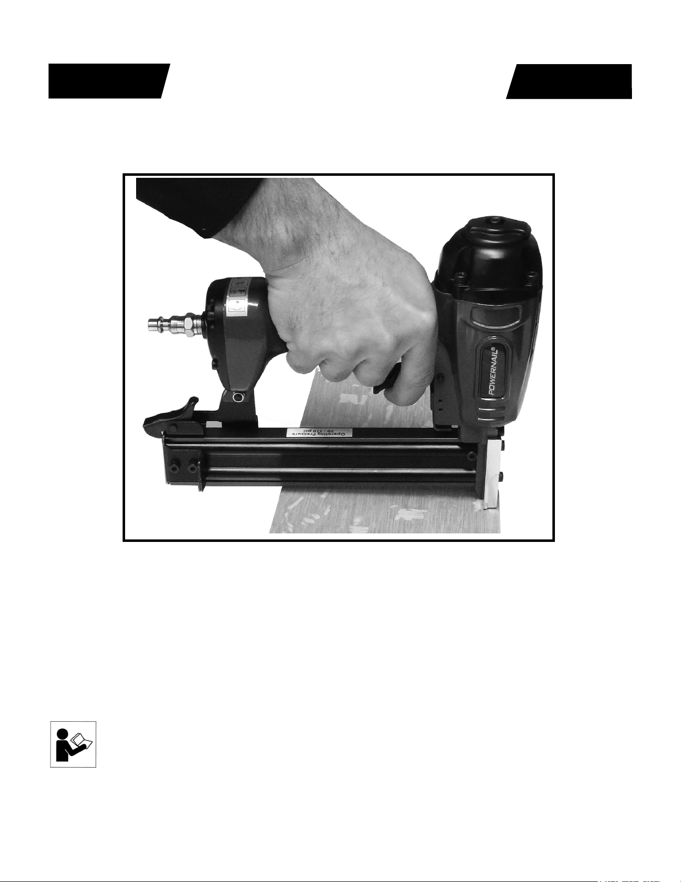
The Model 2000TN trigger-pull top nailer is designed to bring Powernail quality and fl ooring
expertise to a pneumatic nailer. The Model 2000TN is designed for use with 1” and 1-1/4”, 20
gauge L-Cleat Powernails
®
.
INTRODUCTION
INDEX
LIMITED WARRANTY
POWERNAIL® Company, Inc. warrants to its customer, and to the fi rst end-use
purchaser of POWERNAIL Model 2000TN POWERNAILER purchased from an
authorized POWERNAIL distributor, that each serialized manufactured Model 2000TN
POWERNAILER by POWERNAIL®, for a period of 12 months from the date of purchase;
shall be free of defects in materials and workmanship and will meet POWERNAIL’S
specifi cations in eff ect at the time of product shipment. POWERNAIL will repair or
replace, at its option, any Model 2000TN POWERNAILER that does not conform to
this warranty. Claims must be made no later than fi fteen (15) days after the end of the
warranty period. POWERNAIL will perform all repair or replacements itself or through its
authorized contractors. POWERNAIL is not responsible for shipping, labor or other direct
or indirect costs. Damage caused by abuse, misuse, unusual or excessive wear is excluded.
Repair or modifi cation of the Products by unauthorized parties will void this warranty.
The customer is responsible for returning Products to POWERNAIL for verifi cation of
nonconformance. Warranties for Products not manufactured by POWERNAIL are limited
to warranties provided to POWERNAIL by the manufacturer of such product that are
assignable to customer.
THESE WARRANTIES AND REMEDIES ARE EXCLUSIVE OF ALL OTHERS,
EXPRESS OR IMPLIED. THE WARRANTIES OF MERCHANTABILITY AND
FITNESS FOR PURPOSE ARE EXPRESSLY EXCLUDED. IN NO EVENT SHALL
POWERNAIL’S LIABILITY FOR A WARRANTY CLAIM EXCEED THE PRICE PAID
TO POWERNAIL FOR THE NONCONFORMING PRODUCT, REGARDLESS OF THE
FORM OR BASIS OF THE CLAIM OR CAUSE OF ACTION.
Index..................................... 2
Warranty............................... 2
Safety Instructions................ 3
Operating the tool................. 4
Air Supply............................. 7
Safety Labels........................ 7
Maintenance......................... 7
Troubleshooting Chart.......... 5
Parts List......................... 8
Schematic........................ 9
Phone Support..................... 12
Web Site.............................. 12
Powernail Company Info..... 12
SAFETY INSTRUCTIONS
3
When operating this Nailer, the operator and others in the work area should ALWAYS wear approved
SAFETY GLASSES, with front and side eye protection. Eye protection will help guard against fl ying
nails and debris, which could cause severe eye injury.
EAR PROTECTION should be used to prevent hearing damage when there are high noise levels
in the work area. ALWAYS use ear plugs with a noise reduction rated at 29 db or higher at a
construction site.
Nailer noise ratings are at LPA-1sd=90.6,
LWA-1sd=99.3 and LPA-1s,1m=86.3.
Nailer vibration rating: m/s2=3.05.
Always DISCONNECT THE AIR SUPPLY before making any adjustments, repairing, clearing jams or when the
Nailer is not in use. Do not use on scaff olding or ladders and disconnect nailer from air supply when transporting
between installation areas.
Never attach the female end of a quick disconnect to the Nailer. This will trap air inside the Nailer and permit it to
be discharged. Only the unrestricted male connection should be attached to the Nailer.
Nailer requires an air source that can continuously deliver 70 to 110 psi at 3-1/2 cubic feet of air per minute for
operation.
Normal air pressure should not exceed 110 psi or damage to the Nailer and seals may occur. Excess air
pressure can cause the Nailer to explode.
To prevent fi re or explosion, use only regulated compressed air—do not use bottled gases of any kind (no
oxygen or combustible gasses) to power this Nailer.
Nailer is intended for use installing wood fl ooring and is not to be used for purposes not specifi ed in the
operations manual.
Do not use any nails other than Powernail® Powercleats which are 20 gage L-cleat nails specifi cally designed
for use in any 20 gage Powernailer. Powercleat nails are available in lengths of 1” and 1-1/4”. Contact your
Powernail Dealer for the correct Powercleats for the Model 2000TN.
Use only Powernail replacement parts in the repair or maintenance of this nailer. Parts or repair services are
available from the manufacturer or from agents authorized by the manufacturer. Repairs should be carried out
only by trained service personel in the fi eld of fastener driving tools who will observe proper safety controls while
performing maintenance. Service personel should be qualifi ed to assess the safe working condition of fastener
driving tools.
Always make sure Nailer is empty of nails before connecting air hose, so as to prevent any accidental discharge
from occurring. ONLY CONNECT AIR TO AN UNLOADED NAILER.
Do not depress the trigger when loading. If the fasteners are jammed, disconnect the tool from the air supply
before you remove the jammed nails.
Never place any part of the body in the discharge path of the Nailer when air is connected to the
Nailer. Never point the tool at yourself or others, even if the tool is not loaded. For safety, keep out of
reach of children. Never leave the Nailer unattended while it is connected to an air supply.
Do not fi re into hard materials or attempt to use on hard or brittle material such as concrete, steel
or tile. Before using this tool, carefully check that all parts are working correctly. Do not use the tool if it is not
operating correctly, check for causes and adjust as necessary for proper operation. When not in use, the tool
should be cleaned, fully assembled and then stored in a dry location. This will extend the life of the tool and
reduce any oxidation.
4
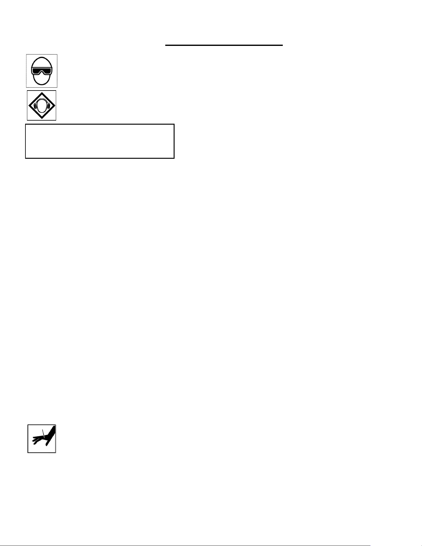
To use the Model 2000TN, simply place
the silver foot of the nailer against the
fl ooring you wish to nail so that the safety
mechanism is engaged. Gently squeeze
the trigger and the nailer will drive and
countersink the nail.
OPERATION
Adjustable
Exhaust
Port
Floor activated safety mechanism
prevents accidental tool activation.
Trigger-pull Operation!
Silver
Nailer Foot

5
PROBLEM POSSIBLE CAUSE SOLUTION
1
Air leaking at
Trigger area
1. O-ring (31) in trigger valve is damaged.
2. Trigger valve head (30) is damaged.
3. Trigger valve stem (35), seal (29) or O-ring (31)
is damaged.
1. Check and replace O-ring.
2. Check and replace trigger
valve head.
3. Check and replace trigger valve stem,
seal or O-ring.
2
Air leaking between
body and drive guider
Damaged bumper (22). Check and replace bumper.
3
Air leaking between
body and cylinder cap
1. Screw loose (5).
2. Damaged gasket (8).
1. Tighten screws.
2. Check and replace gasket.
4
Blade driving
fastener
too deeply
1. Worn bumper (22).
2. Air pressure is too high
1. Replace bumper.
2. Adjust the air pressure.
5
Runs slowly or
has loss of power
1. Insuffi cient oil.
2. Insuffi cient air supply.
3. Broken spring in cylinder cap (8a).
4. Exhaust port (3) in cylinder cap is blocked
1. Lubricate as instructed
2. Check air supply.
3. Replace spring.
4. Replace damaged internal parts.
6
Tool skips a fastener
1. Worn bumper (22) or damaged spring (57).
2. Dirt in gate (50).
3. Inadequate airfl ow to tool.
4. Worn or dry O-ring (17) on piston.
5. Cylinder cap seal leaking (8).
1. Replace bumper or pusher spring.
2. Clean drive channel of front plate.
3. Check hose and compressor fi ttings.
4. Replace O-ring or lubricate.
5. Replace seal.
7
Fasteners are
jammed
(see page 10)
1. Joint guider is worn (24).
2. Fasteners are wrong size or damaged.
3. Magazine or front plate screws are loose (78).
4. Blade (27) in piston assembly is damaged.
1. Replace joint guider.
2. Use the recommended and
undamaged fasteners.
3. Tighten screws.
4. Replace piston assembly.
8
Tool will not drive
down tight
1. Worn blade in piston assembly.
2. Lack of power.
3. Slow cycling and loss of power.
1. Replace piston assembly.
2. Adjust to adequate air pressure.
3. Check cylinder cap spring for
broken coils or reduced length.
Check if exhaust port of cylinder
cap is restricted.
Here are some common issues that may occur during use.
If the nailer is not working as it should, stop using the tool immediately and resolve the
issue before continuing.
TROUBLE SHOOTING CHART
6
CONNECTING THE TOOL TO AN AIR SUPPLY
Your air tool is fully assembled when you receive it. Before using it, attach the air line and
desired air system accessories. Be sure the air hose is depressurized when installing or
removing adapters to the air line. To prevent misfi re, do not connect air to a loaded nailer.
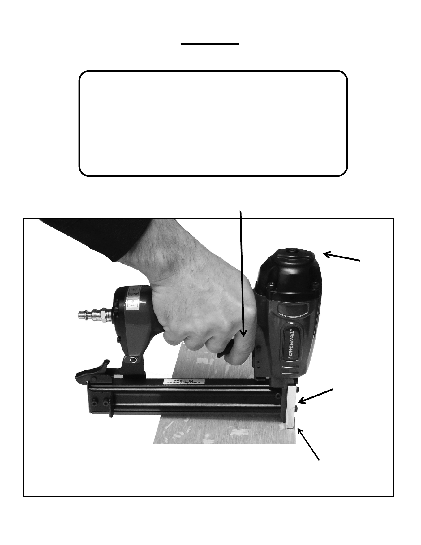
LOADING THE FASTENERS
1. Depress the LOCK (61) to release the
MOVABLE CHANNEL GUIDE (44) and
slide the channel guide out fully as shown
in Figure 3.
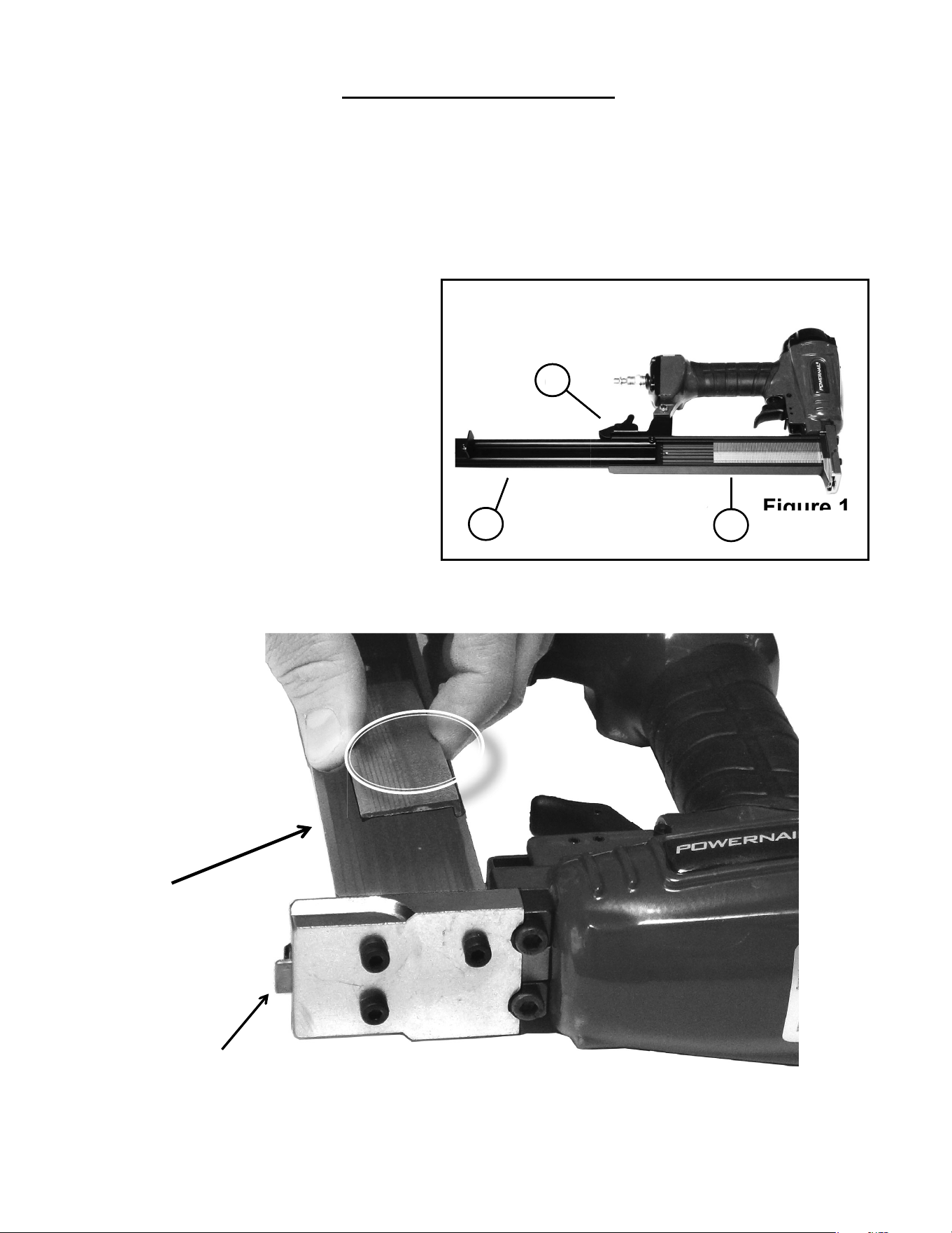
2. Place a full stick of 1” or 1-1/4” 20 gage
Powercleats into the FIXED CHANNEL
(43).
Lay the stick of nails with the L-shape
facing inward towards the center of the
channel (See Figure 2).
3. Slide the MOVABLE CHANNEL GUIDE
(44) forward until it is locked.
OPERATION, continued...
Figure 1.
Lay the stick of
nails into the fi xed
channel with the
L-shape facing
inward towards
the center of the
channel.
44
43
61
Figure 1
61
Floor activated safety mechanism
prevents accidental tool activation.
Figure 2.
1. An automatic airline oilier is recommended but oil
may be added manually before every operation or after
about 1 hour of continuous use.
2. Place two (2) drops of air-tool oil in the air plug as
shown (Figure 3). If you are using an automatic in-line
oiler, check and add oil if necessary.
3. Turn your compressor on and set the compressors
pressure regulator to the proper pressure for the size
and type of fastener being used. Normal operating
pressure should be adjusted between 70-110 psi
based on fastener and wood being used.
4. Connect the tool to the air supply.
7
MAINTENANCE
Figure 3.
WARNING!
1. Read and understand operating manual
before using.
2. Operator and all the by-standers must wear
ANSI approved safety glasses, ear and head
protections.
3. Never use oxygen or other fl ammable gases.
Only choose clean dry regulated compressed
air below 110 PSI pressure.
4. Remove fi nger from trigger while not
operating.
5. Never trip over the hose. Make sure all
connections are tight.
6. Disconnect the tool from air supply before
clearing jams, serviceing, adjusting or during
non-operation.
7. Don’t point tool at people or animals while
operating.
MODEL
2000
1” - 1-1/4“ (25mm - 32mm) Length
USE 20 GAUGE POWERCLEATS
NAILER SAFETY LABELS
Operating Pressure
70 - 100 psi

8
ITEM DESCRIPTION
Avail.
PART #
1 SCREW M4 x 10mm n/a
2 BUSHING n/a
3 EXHAUST COVER n/a
4 WASHER n/a
5 SCREW M5 x 20mm n/a
6 SPRING WASHER 5 n/a
7 CYLINDER CAP 09-20FN2007
8 GASKET
S
09-20FN2008
8a SPRING 09-20FN20082
9 VALVE SEAT 09-20FN2009
10 O-RING 15.7 x 2
KIT
09-20FN2010
11 O-RING 38.8 x 3
KIT
09-20FN2011
12 VALVE 09-20FN2012
13 O-RING 33.5 x 3.5
KIT
09-20FN2013
14 STOPPED WASHER n/a
15 COLLAR n/a
16 O-RING 50.5 x 2.5
KIT
09-20FN2016
17 O-RING 28.3 x 3
KIT
09-20FN2017
18 PISTON ASSM w/DRIVE BLD
S
09-20TN5018
19 CYLINDER
S
09-20FN2019
20 O-RING 36.3 x 2.5
KIT
09-20FN2020
21 O-RING 35.3 x 2.5
KIT
09-20FN2021
22 BUMPER
S
09-20FN2022
23 BODY n/a
24 JOINT GUIDE
S
09-20FN2024
25 SAFE GUIDE n/a
26 SPRING
S
09-20FN2026
27 DRIVE BLADE
n/a
See #18
28 SPRING PIN 3 x 26 n/a
29 SEAL n/a
30 TRIGGER VALVE HEAD n/a
31 O-RING 15 x 1.9 n/a
32 TRIGGER VALVE GUIDE n/a
33 O-RING 5.5 x 1.5 n/a
34 SPRING n/a
35 TRIGGER VALVE STEM n/a
36 SPRING n/a
37 WASHER
S
09-20FN2037
38 TRIGGER ASSEMBLY n/a
ITEM DESCRIPTION
Avail.
PART #
39 TRIGGER PIN n/a
40 SCREW M4 x 16mm n/a
41 WASHER n/a
42 .125 DIA x .312 ROLL PIN
S
09-20FN2042
43 CHANNEL
S
09-20FN2043
44 CHANNEL GUIDE
S
09-20FN2044
45 CHANNEL BRACKET
S
09-20FN2045
46
M4-0.7 x 10mm S.H.C.S. (CH
BRACKET & PLATE)
S
09-20FN2046
47
M4-0.7 x 14mm B.H.C.S. (PUSH-
ER STOP)
S
09-20FN2047
48 LOCK PLATE
S
09-20FN2048
49 M4-0.7 x 5mm S.H.C.S.
S
09-20FN2049
50 GATE
S
09-20TN5050
51 M4-0.7 x 16mm F.H.C.S.(w/patch)
S
09-20FN2051
56 NAIL PUSHER
S
09-20FN2056
57 SPRING
S
09-20FN2057
58 LOCK PIN
S
09-20FN2058
59 LOCKING WASHER
S
09-20FN2059
60 TORSION SPRING
S
09-20FN2060
61 LOCK
S
09-20FN2061
65 AIR PLUG n/a
66 NUT M5 09-20FN2066
67 M5-0.8 x 18mm S.H.C.S. (Bracket)
S
09-20FN2067
68 SOFT GRIP SLEEVE n/a
69 GASKET n/a
70 END CAP n/a
71 FOOT
S
09-20TN5071
72 GATE PLATE
S
09-20TN5072
75 SAFETY
S
09-20TN5075
78 M4-0.7 x 14mm S.H.C.S.
S
09-20FN2078
80 M5-0.8 x 20mm S.H.C.S.
S
09-20FS5080
90 Model 2000 Seal Kit
S
09-20FN2090SK
MODEL 2000TN PARTS LIST
KEY: S=Sold Separately, n/a Not available separately, KIT=Sold as part of a Kit
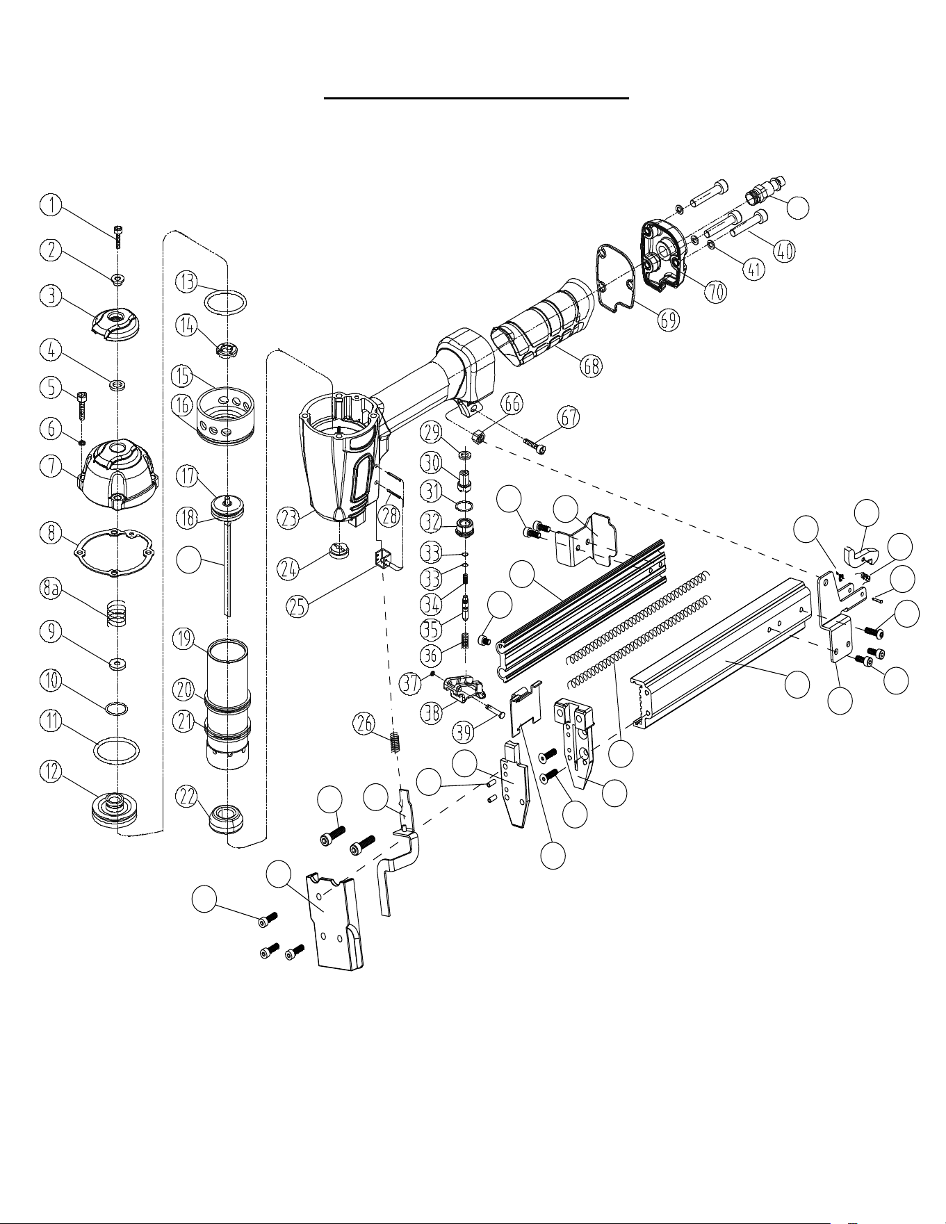
9
MODEL 2000TN SCHEMATIC
46
44
27
65
59
61
60
58
47
46
45
43
57
48
49
56
51
50
42
75
80
78
71
72
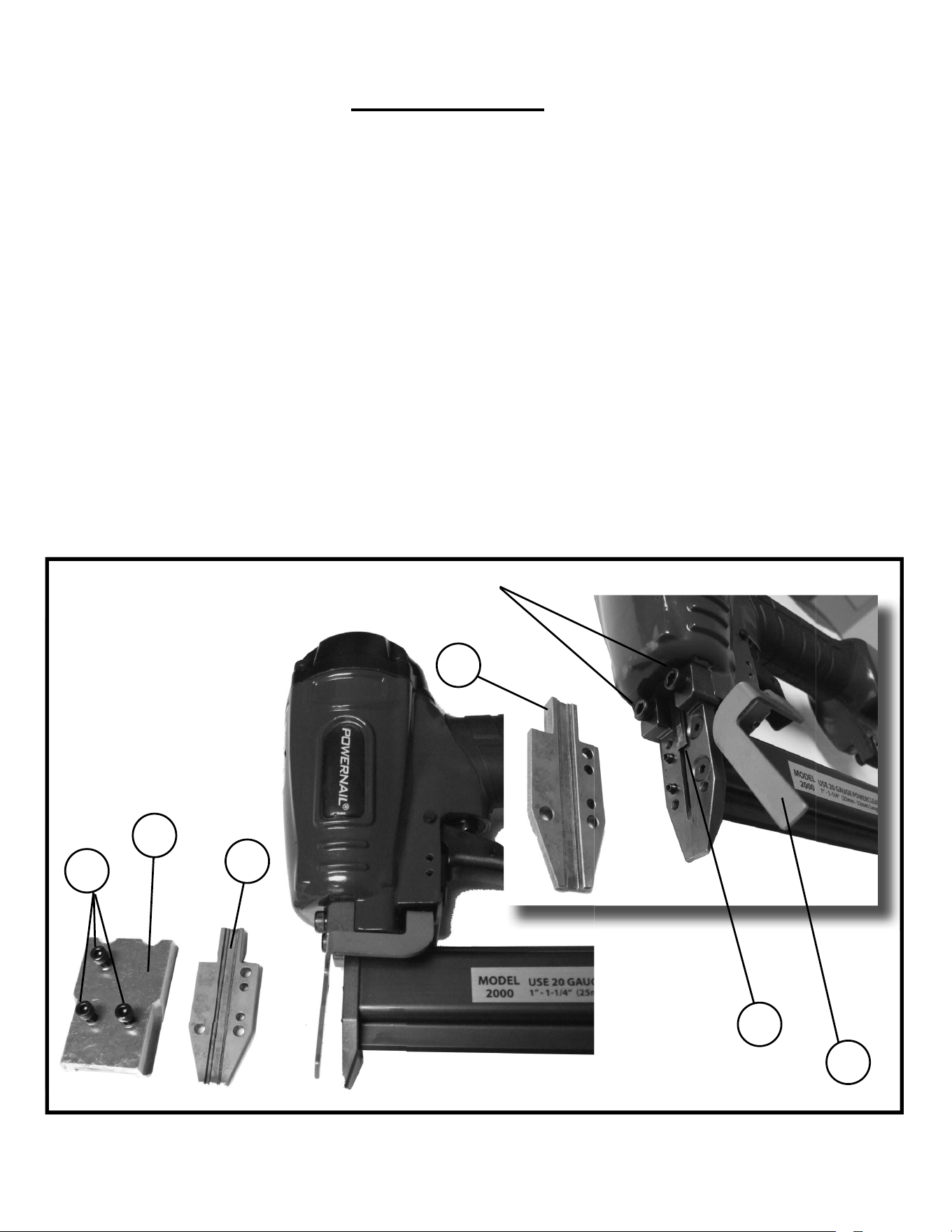
10
CLEARING A JAM
Disassembly: (See Figure 4.)
1) NOTE: Do not remove the two M5 screws (80).
2) Remove three M4 screws (78) with a 3mm allen wrench and lift off foot (71).
3) Slide the safety arm (75) to the side.
4) Lift the gate plate (72) off to clear the jam and inspect the drive blade (27) and its path.
Reassembly:
1) Make sure the drive blade (27) is centered and re-install the gate plate (72).
2) Slide the safety arm (75) back on top of the gate plate (72).
3) Install foot (71) on top of safety arm (75) and gate plate (72).
4) Install three M4 screws (78) and tighten.
(80) DO NOT REMOVE THESE TWO TOP BODY SCREWS
75
71
78
72
72
27
Figure 4.
• Dealer Locator
• Rental Locator
• Parts Store
• Product Information
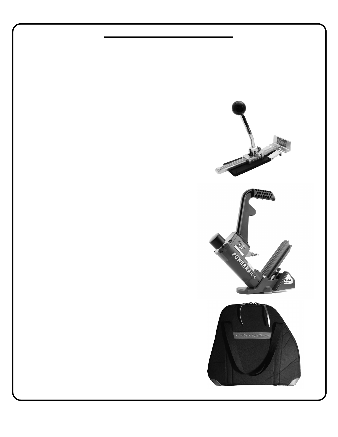
Model 50P FLEX™
The Powernail Model 50P FLEX is truly a fl exible
nailer which can nail down the wide variety of fl ooring
found in today’s market. Using the adjustable foot, you
can fi ne-tune the nailer height according to diff erent
wood profi les. No need for extra shims and pads! The
Powernail Flex is suitable for use on thinner 3/8”,
1/2”, 5/8” and 3/4” solid tongue and groove hardwood
exotics, bamboo, and engineered fl ooring. Part
number: 50PFLEXW
Powerjack® Model 500
Truly a Tinker's TOOL, the POWERJACK Model 500 is
designed to push or pull fl ooring strips into place and hold
them tightly. The PowerJack Model 500 self adjusts from
5/16” to 3/4" thickness fl ooring. It can be used to either push
or pull wood fl ooring strips into place and ratchets tightly
for hands free operation. The base of the PowerJack 500
has mounting holes for mid-fl oor use. Simply screw nail the
PowerJack 500 to your sub fl oor -in front of your fl ooring
strips -and ratchet the fl ooring strips tight. Also great for under
cabinet and kick plate installation.
Part number: PJ500
• Repair Tech Videos
• Cool Tools Cleat Calculator
• Cleat Depth Chart
• Training Schools
Powernailer® TOOL BAG™
The TOOL BAG holds all Powernailer® confi gurations
including the FLEX and POWER ROLLER models.
The Powernail TOOL BAG is built tough with a double
wall of padded industrial nylon to protect your tools.
Corners are reinforced with leather for durability.
Zippered storage pouch on the inside (12” x 6”).
The Tool Bag has two durable handles which can be
used for carrying over your shoulder.
Dimensions: 20” base, 7” deep and 20” Tall.
Part number: 06-99201
Visit www.Powernail.com
Featured Accessory Products
TOOL BAG
Model
50P FLEX
11

12
POWERNAIL COMPANY, INC.
1020 Williams Road, Genoa City, WI 53128
US Phone: 1-800-323-1653 or 262-292-5300
www.powernail.com
