
OPERATOR’S MANUAL
To locate your local Kärcher Commercial Pressure Washer Dealer nearest you,
visit www.karchercommercial.com
HDS3.5/30a HDS4.5/22a
HDS5.0/30b HDS5.0/30c
L
I
S
T
E
D
®
9.801-637.0 - C 01/26/21
98016360-1
GR
OU
N
D
8
10
12
14
16
0
2
4
6
TEMP
9
.
801-
63
3
.0
T
ACH
/
HO
UR
0
2
8
1
4
CHEM%
9
.8
0
1
-6
3
4
.
0
50
200
25
0
3
00
31
5
10
0
1
50
0
1
.
Pl
ace
a
l
l
s
w
i
tch
e
s
i
n
th
e
“OFF”
p
o
si
t
i
o
n
.
2
. C
o
n
n
e
c
t
p
o
we
r
su
p
p
l
y
to
p
rope
rl
y
g
roun
d
e
d
o
u
t
l
e
t. Te
s
t
t
h
e
GF
CI
(i
f e
q
u
i
p
p
e
d
)
u
si
n
g
the
rese
t
a
nd te
s
t
p
ro
ce
du
re
s
p
ro
vi
d
e
d
on
th
e
GFCI
devi
ce
.
Th
e
GFC
I
mu
s
t
b
e
re
se
t
a
n
d
te
ste
d
w
i
t
h
e
v
e
r
y
u
s
e
.
3
.
S
e
cu
r
e
h
i
g
h
p
re
ss
u
re
h
o
s
e
,
sh
u
t-o
ff
g
u
n
a
n
d
w
a
n
d
to
o
u
t
-
l
e
t
4
.
Co
n
n
e
c
t w
a
t
e
r
sup
p
l
y
h
o
se
a
n
d
tur
n
o
n
w
a
te
r
.
5
.
Gra
sp
w
a
n
d
Pl
a
ce
p
u
mp
s
w
i
tc
h
i
n
th
e “ON”
p
o
si
tio
n
.
6
.
T
u
r
n
g
a
s
v
a
l
ve
co
n
trol
kn
o
b
to
“ON”
p
osi
tio
n
.
P
i
l
o
t
wi
ll
l
i
g
h
t
a
u
t
o
mati
ca
l
l
y
w
h
e
n
b
u
r
n
e
r
s
w
i
tc
h
i
s
tu
r
ne
d “ON”
.
7
. To
h
e
a
t
wate
r,
p
l
a
c
e
bu
r
n
e
r
s
w
itch
i
n
th
e
“ON
”
p
o
siti
o
n
a
n
d
a
d
ju
s
t th
e
r
mo
sta
t
to
de
si
re
d
te
mp
er
a
tu
r
e
.
8
. Tu
r
n
o
n
d
e
te
rg
e
n
t
a
n
d
pro
ce
e
d
w
i
t
h cl
e
a
n
in
g
.
9
.
A
fte
r
c
l
e
a
n
i
n
g
:
A.
T
ur
n
o
f
f
d
e
te
rg
e
nt
a
n
d
r
in
s
e
.
B
.
Pla
ce bu
r
n
e
r
s
wi
tch
i
n
th
e
“
O
FF”
p
o
si
t
i
o
n
.
C
.
Al
l
o
w
ma
ch
in
e
to
d
i
sch
a
rg
e
w
a
te
r
f
o
r
2
-3
m
i
n
u
te
s
t
o
c
o
o
l
c
o
i
l
.
D.
P
l
a
c
e
p
ump
s
witch
i
n the “
OFF”
p
o
siti
o
n
.
E
. S
q
u
e
e
z
e
tr
i
g
g
e
r gu
n
to
re
li
ev
e
sy
ste
m
pre
ssu
re
.
F
.
T
ur
n
o
ff
w
ate
r
s
upp
l
y
.
MODE D’EMPLOI
LI
RE LE MAN
UEL D
E
L’
O
PER
A
T
E
UR
AVA
NT
UTI
LISA
TI
O
N
U
NE
M
A
UV
A
ISE
U
T
I
LISATIO
N
PEU
T
C
AU
SER
D
E
S
BLESSUR
ES
O
U
DO
MM
A
G
ES
M
A
TÉ
R
I
ELS
.
INSTR
U
CCIONES
DE
OPE
R
A
CION
LEA
EL MA
N
U
A
L D
E
OPE
R
ACIÓ
N
A
N
TES D
E
US
AR
S
E.
LA
O
PER
A
C
IÓN
IN
A
DE
C
U
A
D
A
P
U
E
D
E
O
C
A
SIO
N
A
R
L
ESION
E
S
PE
R
SON
A
LES
O
DA
Ñ
O
S
A
L
AS
PR
O
P
IED
A
D
ES
.
OP
ERA
T
ING INST
R
UC
T
IONS
R
EAD
O
PERA
TI
NG
MANU
A
L
BEF
O
R
E
O
PERA
TIN
G
MACHI
NE.
IMPR
O
PER
O
PERA
TIO
N
MA
Y
R
ESU
L
T
I
N
PERSO
N
AL
INJ
UR
Y
O
R
PR
O
PE
R
T
Y DA
MA
G
E
.
1
.
Coloq
u
e to
d
o
s
lo
s i
n
t
e
rru
p
tor
e
s
e
n l
a
p
o
sic
i
ón
“
OFF”
(
APAGAD
O)
.
2
.
Cone
ct
e
la
f
u
e
nte
d
e
e
n
e
rg
ía
a
u
n
t
o
ma
co
rr
ie
n
te
co
n
e
c
t
a
d
o
a
t
ie
rr
a
d
e
mo
d
o
a
d-
ecu
ado.
Pru
e
be
e
l
Inte
rru
pto
r
A
cci
o
n
a
d
o
p
or
Cor
ri
e
n
te
d
e Pé
rd
i
d
a
a Tie
rr
a
(GFCI
p
o
r su
s
si
g
l
a
s
e
n
I
n
g
l
é
s
)
(si
h
u
b
i
e
ra
)
m
e
d
i
a
n
te
l
o
s
p
ro
ced
i
mie
nt
o
s
d
e re
inici
o
y
pr
u
e
b
a
i
n
c
o
r
pora
d
o
s
e
n
d
i
ch
o
d
ispo
si
tiv
o
.
E
l
GFCI
d
e
b
e
r
e
i
n
i
ci
a
rse
y p
o
n
e
rse
a
pr
u
e
b
a
c
a
d
a
v
ez
q
ue
s
e
us
e
.
3
.
Ase
g
u
re
la m
angue
r
a
d
e
alta
p
re
sión
,
p
istol
a
y
v
a
r
il
l
a
a
l
a
co
p
lad
o
r
de
l
to
m
a
co
r-
r
i
ent
e.
4
.
Con
e
c
t
e
la
m
an
g
u
era
d
e
s
u
m
i
n
i
stro
d
e
a
g
u
a
y
ab
ra
l
a llave
.
5
.
S
u
jete
la
v
a
r
i
l
la
.
Co
l
o
qu
e
e
l
i
n
te
rru
p
tor
d
e
la b
o
mb
a
e
n
la po
si
ci
ó
n
“ON” (ENC
E
N
DID
O)
.
6.
Co
l
o
q
u
e
la
p
e
r
i
l
l
a
d
e
con
tro
l
d
e
la
vá
l
vu
l
a d
e
g
a
s
e
n
l
a
p
o
si
ción
“
ON
”
(E
N
C
EN
D
I-
DO).
El p
i
l
o
t
o
se
e
n
ce
n
d
e
rá
a
u
to
má
ti
ca
m
e
n
t
e
cu
a
n
do
e
l
q
u
e
mad
o
r se
e
n
ci
e
n
d
a.
7
.
A
d
e
ca
l
e
nta
r
e
l
a
g
u
a,
co
l
o
q
u
e
e
l
i
n
te
rr
u
p
to
r
d
e
l
q
u
e
m
a
d
o
r
e
n
l
a
p
o
s
i
ci
ó
n
“ON”
(ENC
EN
DIDO)
y
a
juste
e
l
t
er
mo
s
t
ato a l
a
tem
p
e
ra
tur
a d
e
se
a
d
a
.
8
.
Enci
e
n
d
a
e
l
d
e
te
rg
e
n
t
e
y
p
ro
ce
da
co
n
l
a l
i
mpieza
.
9
.
De
sp
u
é
s d
e
l
i
mp
i
a
r
:
A.
Ap
a
g
ue
e
l
d
e
te
r
g
en
te
y e
n
j
u
agu
e
.
B
. Po
n
g
a
e
l
i
n
te
r
r
u
p
t
o
r
d
el q
uema
d
o
r
e
n
l
a
p
o
si
ci
ó
n
“OFF”
(A
PA
GA
D
O)
.
C
.
D
e
je
q
u
e
l
a
má
q
uin
a
de
sc
a
rgu
e
a
g
u
a
p
or
2
ó 3
m
i
n
uto
s
p
ar
a
q
u
e
se
e
n
f
ríe
e
l
ser
pe
n
t
ín.
D.
Pon
ga
el
i
n
te
rru
pt
o
r
d
e
la
b
o
mb
a
e
n
la
p
o
si
ci
ó
n “
OFF”
(A
P
AGA
D
O)
.
E.
Pre
si
one
l
a pisto
l
a
p
a
ra
a
l
i
vi
a
r
l
a
p
re
s
ió
n
de
l
si
stem
a.
F.
C
i
e
r
re el
su
m
i
n
i
stro
d
e
a
g
u
a
.
1
.
M
e
tte
z
to
us le
s
i
n
te
rr
u
p
t
e
u
r
s
e
n
p
o
s
i
ti
o
n
“OFF”.
2
.
Co
n
n
e
cte
z l
e
b
l
o
c
d
’
a
l
i
me
nta
ti
o
n
é
le
ct
ri
q
u
e à
u
n
e
p
ri
se
co
rre
c
t
e
me
n
t
m
i
se
à
l
a
te
rre.
T
e
st
e
z
l
e
d
i
sj
o
n
c
t
e
u
r
d
e
fu
ite
de te
rre (l
e
ca
s
é
ch
é
an
t
)
à
l’
ai
de
d
e
s
p
rocé
d
u
re
s
d
e
réiniti
a
l
i
sa
t
i
o
n
e
t d
’
e
ssa
i
i
n
d
i
q
u
é
e
s
su
r
le
d
isj
o
n
cte
u
r.
L
e d
i
sj
o
n
c
t
e
u
r
do
it
ê
t
re
ré
i
n
itia
l
i
sé
e
t
t
e
sté à
ch
a
q
u
e
u
t
i
li
-
sa
tio
n
.
3
.
Fi
xez
le
tuya
u
à
h
a
u
t
e
p
re
ssi
o
n, l
e
p
is
t
o
l
e
t
e
t l
e
tu
be rig
id
e
a
u
r
a
c
c
o
r
d
d
e
so
rt
i
e.
4
.
C
o
n
n
e
ct
e
z
le
tuya
u
à
e
a
u
e
t
f
a
i
t
es co
u
l
e
r
l
’
e
au
.
5
.
Te
n
e
z
l
e
tu
b
e
rig
i
d
e
f
e
rmeme
n
t.
Me
t
te
z l’
i
n
t
e
rru
p
teu
r
d
e l
a
p
o
mp
e
e
n
po
s
itio
n “ON”
.
6
.
Tou
r
n
e
z
l
e
b
o
u
to
n
d
u
r
o
b
i
n
et d
e
ga
z e
n
p
o
si
t
i
o
n
“
ON”
.
L
a
veil
l
e
use
s’
al
l
u
m
e
a
u
tom
a
ti
q
u
eme
n
t
l
o
rsq
u
e
l
’int
e
rru
p
te
u
r
d
u
b
rû
le
u
r
est
mi
s
sur
“ON”
.
7
.
P
ou
r ch
a
u
f
f
e
r
l
’
ea
u
,
m
e
tte
z
l
’
i
n
te
r
rup
t
e
u
r
d
u
b
r
û
l
e
ur
su
r
“ON” e
t
ré
g
l
e
z
l
e
t
h
e
r
mo
sta
t
à
l
a
te
m
p
é
r
a
t
ure
v
o
u
l
u
e.
8
.
A
c
t
i
v
e
z
l
e
d
ét
e
rg
e
n
t
e
t co
mm
e
n
ce
z
le
ne
t
to
y
ag
e.
9
.
A
p
rè
s l
e
n
e
tto
ya
g
e
:
A.
Co
u
p
e
z
l
e
d
ét
e
rg
e
nt
e
t
r
i
n
ce
z.
B
.
Me
t
t
e
z
l’
in
t
e
rr
up
teur
du
b
rû
l
e
u
r
su
r
“OFF”
.
C
.
L
a
i
s
se
z
l
a m
a
ch
i
n
e
é
va
cu
e
r
l
’
e
au
p
e
n
d
a
n
t
2
à
3 mi
n
ut
e
s
,
le
t
e
mp
s q
u
e
l
a
b
o
b
i
n
e
re
f
r
o
i
d
i
ss
e
.
D. Me
tt
e
z l
’
i
n
t
e
rr
u
p
te
ur
d
e
la p
o
mp
e
su
r
“OFF”.
E.
A
cti
o
nn
e
z
le
p
i
s
t
o
le
t
p
o
u
r
ré
d
u
i
re
l
a
p
re
ssi
on
d
u
sys
t
è
me
.
F
. Co
u
p
ez
l’
e
a
u
.
WARNING
P
R
EC
A
U
C
ION / A
V
ERTISSEMENT
T
O
RE
DU
C
E
TH
E
RI
SK
OF
INJ
U
R
Y
RE
A
D
OP
E
RAT
O
R
’
S
MA
NU
AL
C
AREF
UL
LY
BE
FO
R
E
U
S
ING
.
T
H
IS
MA
CH
INE
T
O
B
E
US
E
D
O
N
L
Y
BY
Q
UALI
F
I
E
D
O
P
E
R
ATO
R
S
.
L
EA
E
L
MA
N
U
A
L
O
P
E
R
A
C
I
ON
ANTES
D
E
U
S
A
R
S
E.
E
S
TE
E
QU
I
P
O
D
EBE
S
ER
U
S
A
DO
S
O
L
A
ME
N
T
E
PO
R
O
P
E
R
A
-
D
OR
E
S
C
A
L
I
F
IC
AD
O
S.
L
I
R
E
L
E
M
AN
UE
L
D
E
L’
O
P
E
R
A
T
E
U
R
A
V
A
NT
U
T
I
L
I
S
A
T
I
O
N
. C
E
T
A
P
PA
REI
L
D
OIT
E
T
RE
U
T
I
LI
SE P
A
R
D
E
S
O
P
E
RA
-
T
EU
RS
QU
A
L
I
F
I
E
S
.
RI
S
K
O
F
IN
J
U
R
Y
—
P
R
O
TE
C
T
I
V
E
E
Y
E
-
W
EA
R
AN
D
C
L
O
T
HIN
G
MUS
T
B
E
W
O
RN
.
wh
e
n o
p
e
r
ati
n
g
th
i
s
ma
chi
ne.
P
RO
T
EJA
S
E
L
O
S
O
J
O
S C
U-
A
ND
O
s
e
ope
r
e
es
t
e
e
qu
i
po
.
D
E
S
L
U
N
E
T
T
E
S
D
E
S
E
C
UR
I
T
E
D
OI
V
ENT
E
T
R
E
P
O
R
T
EES
l
ors
qu
e
v
ous
op
e
r
e
z
c
et
app
arei
l
.
RI
S
K
OF
ASP
HY
XI
AT
I
ON
.
Us
e
on
l
y
i
n
we
l
l
v
en
t
i
-
l
a
te
d
ar
e
a.
R
I
E
S
G
O
D
E
A
S
F
IXI
A
.
U
s
e
el
prod
u
c
t
o
en
un
area
d
e
v
ent
i
-
l
ac
i
ón
ad
ec
uad
a.
R
IS
Q
U
E
D
’
A
S
P
H
Y
X
I
E
.
U
t
i
l
i
s
er
dan
s
un e
nd
r
o
i
t
bi
e
n
aéré
.
RISK
O
F
E
L
E
CT
R
O
CU
T
IO
N. C
o
n
ne
c
t
o
nl
y
t
o
p
r
o
p
e
r
l
y
g
r
o
u
nd
ed
o
u
tl
et.
K
e
e
p
al
l
c
o
n
-
n
e
c
ti
o
n
s
dr
y a
nd
of
f
th
e gr
o
un
d.
K
ee
p
s
p
ra
y
a
w
a
y
fr
o
m
el
e
c
tr
i
c
al
w
i
r
i
ng
a
nd
c
om
po
n
e
nt
s
.
Di
s
con
ne
c
t
fr
o
m
e
l
e
c
t
r
i
c
al
s
up
pl
y be
f
ore
s
e
r
v
ic
i
ng
.
R
I
E
S
G
O
D
E
E
L
E
C
T
R
O
C
UC
I
Ó
N
—
C
o
-
necte
el
enc
h
u
f
e
e
n
u
n
c
o
nt
ac
t
o
ad
e
c
ua
d
o
.
M
a
nt
e
nga
to
d
as
l
a
s
c
on
ne
c
c
i
o
nes
s
ec
as
y
ar
ri
ba
d
el
s
u
el
o.
N
o
roc
i
e
c
omp
on
ent
e
s
el
é
c
tri
c
os.
D
e
s
c
on
e
c
t
e
l
a
c
o
rr
i
en
t
e
el
é
c
tri
c
a
ant
es
de
dar
s
erv
i
c
io
.
R
I
SQUE
D
’
E
L
ECTR
O
C
U
T
ION
—
Rel
i
er
à
de
s
pr
i
s
e
s
a
v
e
c
m
i
s
e
à l
a
t
erre
s
e
ul
ement
.
T
ous
l
es
do
i
vent
ê
t
re
mai
nt
enus
s
ec
s
et
é
t
r
e
s
u
s
-
pen
d
us
.
N
o
j
am
a
i
s
proj
et
er
de
l
’
e
au
s
u
r
l
es
c
om-
pos
ant
es
et
él
e
c
t
r
i
q
u
e
s
.
C
o
u
per
l
’
ali
m
e
nt
a
ta
t
i
on
él
e
c
t
r
i
que av
an
t
de
f
a
i
re
un
e
r
é
p
ara
t
i
o
n
.
R
I
S
K
OF
IN
J
E
CT
I
O
N
O
R
S
E-
V
E
RE
IN
JUR
Y
TO
P
E
R
S
O
N
S.
K
ee
p
c
l
ea
r
o
f n
ozz
l
e
.
H
O
T DI
S
CH
AR
G
E
F
LU
ID
—
D
o
no
t t
ou
c
h
or
direc
t dis
c
h
a
r
g
e
s
tr
e
am
at
pe
r
so
ns.
RIE
SG
O
D
E
P
E
N
E
T
R
AC
I
ÓN
O
L
E
SI
ON
E
S
S
E
V
E
R
AS
A
P
E
R
S
O
-
NAS.
Mant
é
nga
s
e f
ue
ra
del
al
c
a
nc
e
de
b
oq
ui
l
l
a
.
DES
C
A
R
G
A
D
E
A
G
U
A
C
A
L
I
ENTE
A AL
T
A
P
R
E
SI
O
N
—
N
o
t
o
que
ni
d
i
ri
j
a
el
de
l
agu
a
a
ot
r
a
s
pe
rs
o
n
as
.
RIS
QU
E
DE
B
L
E
S
SUR
E
S
.
S
e
t
e
ni
r
l
oi
n
des
b
us
e
s
.
E
AU CHA
U
DE
S
O
US
PRES
SI
O
N A
L
A
S
O
R
T
IE
—
N
e
p
as
di
r
i
ger
l
e
j
et
d
’
e
au
ve
rs
des
p
e
r
s
o
nne
s
.
S
P
RA
Y
G
UN
KIC
KS
B
A
C
K
—
Hol
d
w
i
th
bo
th
h
a
nd
s.
L
A
P
I
S
T
O
L
A
SE
M
U
E
V
E
CON
L
A
P
R
E
S
I
Ó
N
—
S
os
t
en
ga c
on
la
s
do
s
m
a
nos
.
L
A
P
O
I
GNEE
PI
S
T
O
L
E
T R
E
-
P
O
U
S
S
E
—
T
enir
à
de
u
x
m
a
in
s
.
R
I
S
K
O
F
IN
J
URY—H
O
T
S
UR
F
ACES
C
AN
C
AU
SE
B
UR
N
S — Us
e
onl
y
de
s
i
g
n
ed
g
r
i
p
p
i
ng
a
rea
s
of
s
p
r
ay
gu
n
and
w
a
n
d.
S
UPE
RF
I
CIE
S
C
A
LI
E
N
TE
S
—
Use
s
olamente
las
área
s
ais
l
a
das
de
l
ga
t
illo
y
la lanz
a.
SUR
F
ACES
CHA
U
DES
—
Touc
her
s
eulement
le
s par
t
ies
is
o
l
é
es
des p
oignée
pis
t
ole
t
s
et
l
a
nc
es
.
RIES
GO DE
E
X
P
L
O
S
I
ON —
U
se
el
pro
ducto en
áre
as
dond
e
e
l
fuego
o
llam
a
s
ean
pe
r
m
iti
d
o
s
.
No
roc
i
e
liquidos
RI
S
Q
UE D’
EXP
LOS
ION
—
U
t
ilis
e
r
au
x
endro
i
ts où un
e
nu
e
est
pe
rmis
e
.
Ne
pas
v
a
poris
er
de
li
q
uides
R
ISK O
F
E
X
PLOSIO
N
. O
perate
o
nly
w
here
open
or torch
is
p
e
rm
itted
.
D
o
not
sp
r
ay
liqui
ds.
R
ISQ
U
E DE FEU
O
U
D
’EXPLO
S
I
ON
R
IESG
O
D
E INC
EN
DI
O
O
E
XPL
O
SI
Ó
N
RI
S
K O
F FI
R
E
O
R
E
XPL
O
SI
O
N
•
M
a
c
hi
n
e
n
ee
d
s
t
o b
e
in
s
talle
d
o
n
n
on
-
comb
u
s
t
i
bl
e
wi
th m
i
n
i
mu
m
c
l
ea
r
a
n
c
e
o
f
18”.
B
efore
l
i
gh
ti
n
g,
s
me
l
l
al
l
arou
nd
t
h
e
a
p
pl
i
a
n
c
e
area
f
o
r
ga
s
. B
e
s
ur
e
to
s
m
ell
n
e
xt
to
th
e
b
e
ca
us
e
s
o
m
e g
a
s
i
s
he
a
v
i
er
th
an
ai
r
an
d
w
i
l
l
s
e
t
tl
e
on
t
he
If
y
o
u
sme
ll
g
a
s, imme
diat
e
l
y
c
al
l
y
o
u
r
g
a
s
su
p
pl
i
e
r
f
o
r
i
nst
r
u
c
t
i
o
n
s. If
g
a
s
s
u
p
p
l
i
e
r
c
a
n
n
o
t
b
e
r
ea
c
hed
,
ca
l
l
th
e
d
e
p
artm
e
n
t
.
D
o no
t
u
se to
ol
s
to
pu
s
h
in
o
r
turn
th
e ga
s
c
o
ntr
o
l
kn
o
b
.
I
f k
n
o
b
w
i
ll
no
t
pu
s
h
i
n
or
turn by
h
a
nd
,
c
all
a
s
er
v
i
c
e
te
c
h
n
ic
i
a
n.
Us
i
ng
fo
r
c
e
or
at
t
em
pti
ng
r
e
pa
ir
ma
y
r
e
s
ul
t
i
n
a
or ex
pl
o
s
i
on.
S
h
o
ul
d
pi
l
o
t
outag
e occur
,
t
u
r
n
c
o
ntr
o
l
kn
o
b
to
OFF
p
o
s
i
tion
.
Wai
t 5
mi
n
u
t
e
s be
fore
r
e
l
ig
ht
i
n
g.
D
o
no
t
us
e
th
is
eq
uip
men
t
i
f
an
y
pa
r
t ha
s
be
en
u
n
de
r
w
at
e
r.
Imm
ed
ia
te
l
y c
a
ll
a
s
e
r
v
i
c
e
te
c
hn
ic
i
a
n
to
i
nsp
ec
t
fo
r
r
e
p
a
ir
.
E
l
eq
ui
p
o
de
be
s
e
r
i
ns
t
a
l
ad
o
s
obre
un
pi
s
o
r
e
s
i
s
t
en
te
al
i
nc
e
ndio, c
o
n
un
es
p
ac
i
o
l
i
br
e
de
1
8”
mini
mo
.
A
nt
es
de
en
cen
de
r
, olf
at
ee
al
r
e
d
e
do
r
d
e
l
a
p
ara
t
o
p
a
r
a
de
te
c
ta
r
ga
s
. E
s
t
é
s
e
g
uro de
r
e
v
i
s
ar
ce
r
c
a
de
l
pi
so
,
po
r
q
ue
ci
er
t
o
s
g
a
s
es
son
más
pe
s
ad
os
q
ue
e
l
a
i
r
e
. S
i
ol
f
at
ea
ga
s
,
av
i
s
e
i
nm
e
di
a
tam
ent
e a
s
u
pr
o
v
ee
do
r
d
e
ga
s
.
Al
no
loc
a
l
iz
a
r
el
pr
o
v
ee
do
r,
l
lame
a
l
o
s
b
o
mb
er
o
s
.
No
use
h
erram
ien
t
as
p
ara
mo
v
er
el
c
o
ntr
o
l d
e
l
ga
s.
S
i
l
a
m
an
i
j
a
n
o
s
e
p
u
e
de op
e
r
a
r c
o
n
l
a
m
a
n
o
,
l
l
am
e
a
un
té
cni
co
c
a
paci
ta
do
.
F
orz
ar
o
inte
nt
ar
rep
ar
a
r es
t
e
c
o
ntr
o
l pu
ed
e
r
es
ul
ta
r e
n
u
n
in
cen
dio
o
e
x
p
lo
s
ión
.
E
n el
c
a
s
o
de
ap
ag
a
r
s
e el
pi
l
oto
,
ap
ag
u
e
y
es
pere
5
m
i
n
ut
os
a
n
t
es
de
en
c
e
n
der.
No
ut
ili
c
e
es
t
e e
q
ui
p
o
en
el
c
aso
qu
e
hu
b
i
e
r
a
es
t
ad
o
sum
e
r
gid
o
e
n
a
gua
p
a
rc
ial o
to
t
alment
e
un
c
om
po
-
nente. C
o
nsul
te c
o
n un t
éc
n
i
c
o
d
e
s
e
r
v
i
ci
o
.
N
e
pa
s
i
ns
t
all
er
c
e m
ac
h
i
ne
au
x
en
d
r
o
i
ts
où
i
l
y
a
de
s
c
ombus
t
ib
l
e
s
(mê
m
e
l
e
s
p
l
a
n
c
h
er
)
d
e
da
n
s
u
n
d
e
m
i-m
è
t
r
e
.
Av
an
t
l
’
a
l
l
u
ma
g
e
,
a
utou
r
d
e
l’
a
pp
a
rei
l
p
o
u
r
d
e
s
s
ente
ur
s
de
ga
z
.
l
es
o
de
ur
s
p
r
ès
d
u
pl
a
nc
h
er
ca
r
c
er
ta
i
ns
ga
z s
o
n
t
plu
s
l
ou
r
d
s
qu
e
l
’
ai
r
e
t
s
’
a
c
cum
u
l
e
nt
s
ur
l
e p
l
a
nc
h
er.
S
i
vou
s
d
é
te
cte
z
un
e
od
eu
r
de
ga
z
,
ap
pe
l
e
z
i
m
méd
i
a
t
e
me
n
t
v
o
t
r
e
f
o
ur
ni
s
s
e
ur
de
ga
z
.
S
i cel
u
i
-c
i
ne
pe
u
t
êt
r
e
jo
i
nt,
ap
pele
r
l
e
d
é
pa
rte
m
en
t d
es
in
c
e
n
di
e
s.
N
e
pa
s
ut
ili
s
e
r
d’ou
til
s
p
o
u
r
pou
s
s
e
r
ou
t
o
ur
n
er
l
a
s
o
upap
e
d
e
c
o
ntrô
le
d
u
g
a
z
.
Si
l
a s
o
u
p
a
p
e
ne
p
eut
ê
t
r
e
e
n
f
o
nc
é
e
o
u
t
ou
r
n
é
e
à
l
a
m
a
i
n
,
a
p
p
el
e
r
u
n
t
ec
h
n
ic
i
e
n
Fo
r
c
e
r
o
u
e
s
s
a
y
e
r
de
r
é
pa
r
er
pe
u
t
c
au
s
er un
feu
ou
un
e
e
x
pl
o
s
i
on.
Si
le
p
i
lo
t
e
s
’
é
tei
n
t
,
to
ur
ne
r
la
sou
pape
d
e
contrô
l
e
en
p
o
s
i
tio
n O
FF
.
A
tte
nd
r
e
5
m
i
n
ut
e
s
avan
t
d
e
r
é
al
l
u
me
r
.
N
e
p
a
s
u
t
il
i
se
r
c
et
é
q
u
i
pe
m
e
nt
si u
ne
p
a
r
t
ie
a
é
t
é
i
mme
rg
é
e
da
n
s
l’e
au
.
A
p
p
e
le
r
u
n t
e
c
h
ni
c
i
en
p
o
ur
in
s
pe
c
te
r
c
e
lu
i
-
c
i
.
8.
9
00-
990.
0
CHAUD!
Motor
Motor On
RM110 Conditioner
Burner
Not all machines have all symbols
Identification of Operational Label Symbols
SYMBOLS

3
CONTENTS
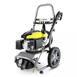
9.801-637.0 - C • Kärcher Classic Operator's Manual
Identification of Operational Label Symbols 2
Introduction & Safety Information 4-6
Component Identification 7
Installation HDS 3.5/30a, 4.5/22a, 5.0/30b, 5.0/30c 8
Installation 9-15
Assembly Instructions 16
Operating Instructions 17
Applying Detergent & General Washing Techniques 18
Shutting Down & Cleanup 19
Storage 19
Troubleshooting 20-23
Maintenance & Service 24
Heating Coils 24
Propane Gas 25
Burner Features 25-26
Basic Facts 27
Equivalents and Oil Change 28
Preventative Maintenance 29
9.801-637.0 - C • Kärcher Classic Operator's Manual
MANUAL
PRESSURE WASHER
4
INTRODUCTION & IMPORTANT SAFETY INFORMATION
Thank you for purchasing this Pressure Washer.
We reserve the right to make changes at any time
without incurring any obligation.
Owner/User Responsibility:
The owner and/or user must have an understand-
ing of the manufacturer’s operating instructions and
warnings before using this pressure washer. Warning
information should be emphasized and understood.
If the operator is not fluent in English, the manufac-
turer’s instructions and warnings shall be read to and
discussed with the operator in the operator’s native
language by the purchaser/owner, making sure that
the operator comprehends its contents.
Owner and/or user must study and maintain for future
reference the manufacturers’ instructions.
The operator must know how to stop the machine
quickly and understand the operation of all controls.
Never permit anyone to operate the engine without
proper instructions.
SAVE THESE INSTRUCTIONS
This manual should be considered a permanent
part of the machine and should remain with it if
machine is resold.
When ordering parts, please specify model and
serial number. Use only identical replacement
parts.
This machine is to be used only by trained operators.
IMPORTANT SAFETY
INFORMATION
WARNING: If you do not follow these instructions
exactly, a fire or explosion may result, causing
property damage, personal injury or loss of life.
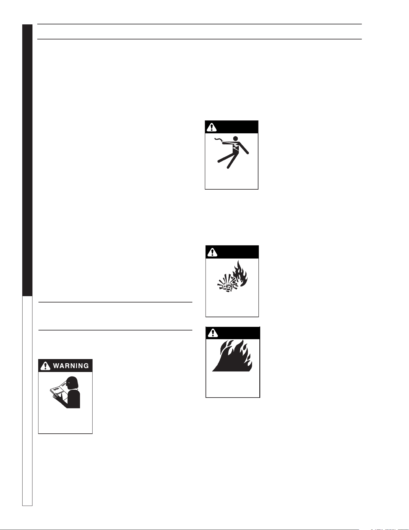
WARNING: To reduce the risk of
injury, read operating instruc-
tions carefully before using.
1. Read the owner's manual
thoroughly. Failure to follow
instructions and warnings
could cause malfunction of
the machine and result in
death, serious bodily injury
and/or property damage.
2. Know how to stop the machine and bleed pressure
quickly. Be thoroughly familiar with the controls.
3. Stay alert — watch what you are doing.
4. Use only your hand to push in or turn the gas
control knob. Never use a tool. If the knob will not
push in or turn by hand, don't try to repair it; call
a qualified service technician.
READ OPERATOR’S
MANUAL THOROUGHLY
PRIOR TO USE.
5. All installations must comply with local codes.
Contact your electrician, plumber, utility company
or the selling distributor for specific details.
DANGER: Improper connection of the equipment-
grounding conductor can result in a risk of electro-
cution. Check with a qualified electrician or service
personnel if you are in doubt as to whether the
outlet is properly grounded.
WARNING: Keep wand, hose,
and water spray away from
electric wiring or fatal electric
shock may result.
6. To protect the operator from
electrical shock, the machine
must be electrically ground-
ed. It is the responsibility
of the owner to connect this
machine to a grounded receptacle of proper
voltage and amperage ratings. Do not spray
water on or near electrical components.
Do not touch machine with wet hands or while
standing in water. Always disconnect power
before servicing.
RISK OF EXPLOSION:
IF GAS SMELL
PRESENT TURN OFF
SUPPLY
WARNING
WARNING: Flammable liquids
can create fumes which can
ignite, causing property dam-
age or severe injury.
WARNING: Risk of explosion —
Operate only where open flame
or torch is permitted. Do not
spray flammable liquids.
RISK OF FIRE.
DO NOT ADD FUEL
WHEN OPERATING
MACHINE.
WARNING
WARNING: Risk of fire — Do not
change LP tanks when the
product is operating or still hot.
WARNING: Use vapor fuel only.
7. Gas appliances shall be
installed only in locations
where combustible dusts and
flammable gases or vapors
are not present. Do not store
or use gasoline near this
machine.
WARNING: In the event of a pilot outage, wait
at least five minutes to clear out any gas before
relighting.
8. Keep operating area clear of all persons.
WARNING
KEEP WATER
SPRAY AWAY FROM
ELECTRICAL WIRING.
9.801-637.0 - C • Kärcher Classic Operator's Manual
5
PRESSURE WASHER
MANUAL
IMPORTANT SAFETY INFORMATION
WARNING
USE PROTECTIVE
EYE WEAR
AND CLOTHING
WHEN OPERATING
THIS EQUIPMENT.
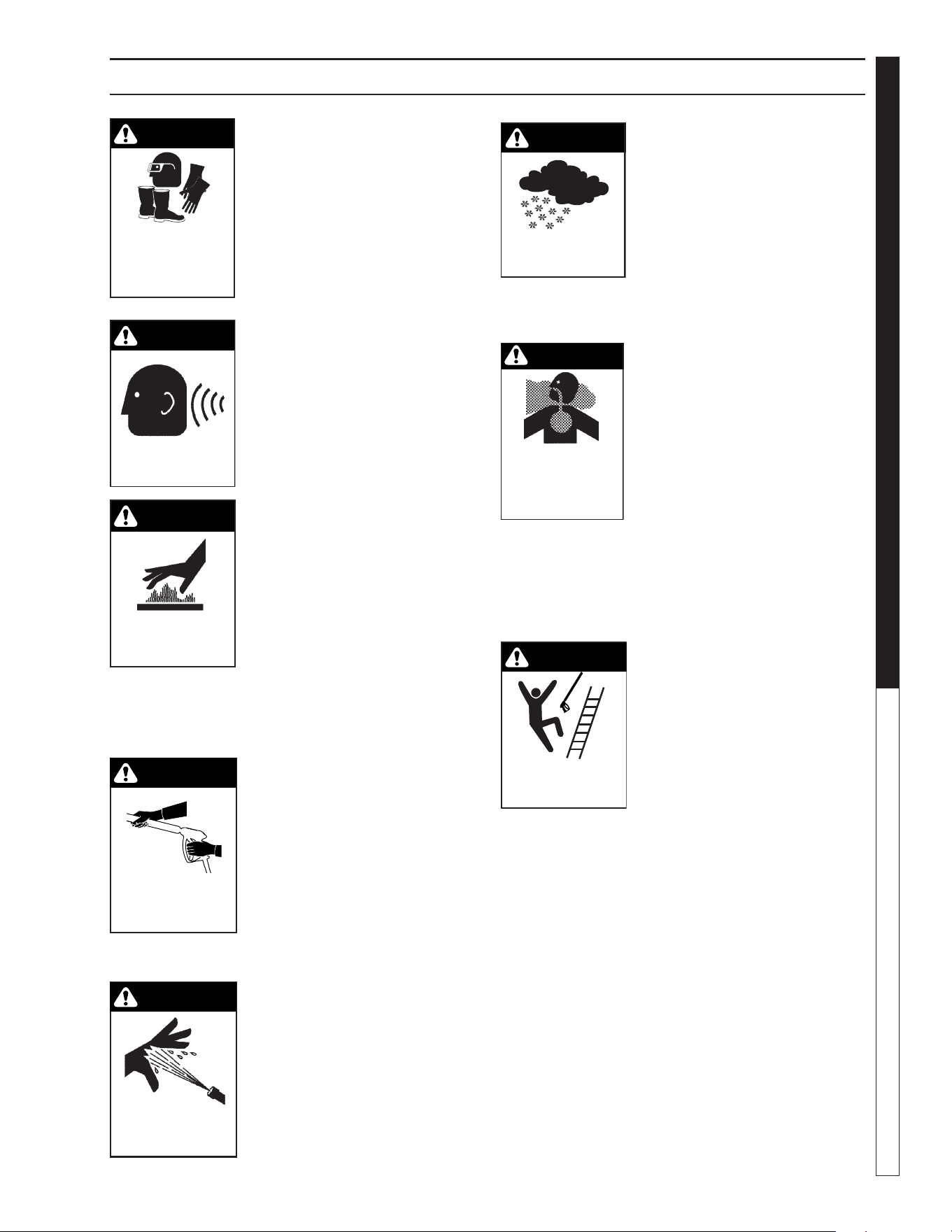
WARNING: High pressure spray
can cause paint chips or other
particles to become airborne
and fly at high speeds. To avoid
personal injury, eye, hand and
foot safety devices must be
worn.
9. Eye, hand, and foot protec-
tion must be worn when
using this equipment.
WARNING
EAR PROTECTION
MUST BE WORN
WARNING: This machine ex-
ceeds 85 db appropriate ear
protection must be worn.
WARNING
RISK OF INJURY.
HOT SURFACES
CAN CAUSE BURNS
WARNING: Risk of injury. Hot
surfaces can cause burns. Use
only designated gripping areas
of spray gun and wand. Do not
place hands or feet on non-in-
sulated areas of the pressure
washer.
10. To reduce risk of injury, close supervision is neces-
sary when a machine is used near children. Do not
allow children to operate pressure washer. This
machine must be attended during operation.
TRIGGER GUN KICKS
BACK - HOLD WITH
BOTH HANDS
WARNING
WARNING: Grip cleaning wand
securely with both hands be-
fore starting. Failure to do this
could result in injury from a
whipping wand.
11. Never make adjustments on
machine while in operation.
12. Be certain all quick coupler
fittings are secured before
using pressure washer.
RISK OF INJECTION
OR SEVERE INJURY
TO PERSONS. KEEP
CLEAR OF NOZZLE.
WARNING
WARNING: High pressure de-
veloped by these machines will
cause personal injury or equip-
ment damage. Keep clear of
nozzle. Use caution when op-
erating. Do not direct discharge
stream at people, or severe
injury or death will result.
WARNING
PROTECT FROM
FREEZING
WARNING: Protect machine
from freezing.
13. To keep machine in best
operating conditions, it is
important you protect machine
from freezing. Failure to protect
machine from freezing
could cause malfunction of the
machine and result in death,
serious bodily injury, and/or property damage. Fol-
low storage instructions specified in this manual.
WARNING
RISK OF
ASPHYXIATION. USE
THIS PRODUCT ONLY
IN A WELL
VENTILATED AREA.
WARNING: Risk of asphyxiation.
Use this product only in a well
ventilated area.
14. Avoid installing machines in
small areas or near exhaust
fans. Adequate oxygen is
needed for combustion or
dangerous carbon monoxide
will result.
15. Manufacturer will not be liable for any changes
made to our standard machines or any compo-
nents not purchased from us.
16. The best insurance against an accident is precau-
tion and knowledge of the machine.
WARNING
RISK OF INJURY
FROM FALLS WHEN
USING LADDER.
WARNING: Be extremely careful
when using a ladder, scaffold-
ing or any other relatively un-
stable location. The cleaning
area should have adequate
slopes and drainage to reduce
the possibility of a fall due to
slippery surfaces.
17. Do not overreach or stand on unstable support.
Keep good footing and balance at all times.
18. Do not operate this machine when fatigued or
under the influence of alcohol, prescription medi-
cations, or drugs.
19. Follow the maintenance instructions specified in
the manual.
WARNING: Use vapor fuel only.
20. The LP models are designed to run on vapor pro-
pane fuel. Do not use liquid fuel. Have a qualified
serviceman install and service your equipment.
21. Never expose a spark or flame where there may
be unburned gas present.
9.801-637.0 - C • Kärcher Classic Operator's Manual
MANUAL
PRESSURE WASHER
6
IMPORTANT SAFETY INFORMATION
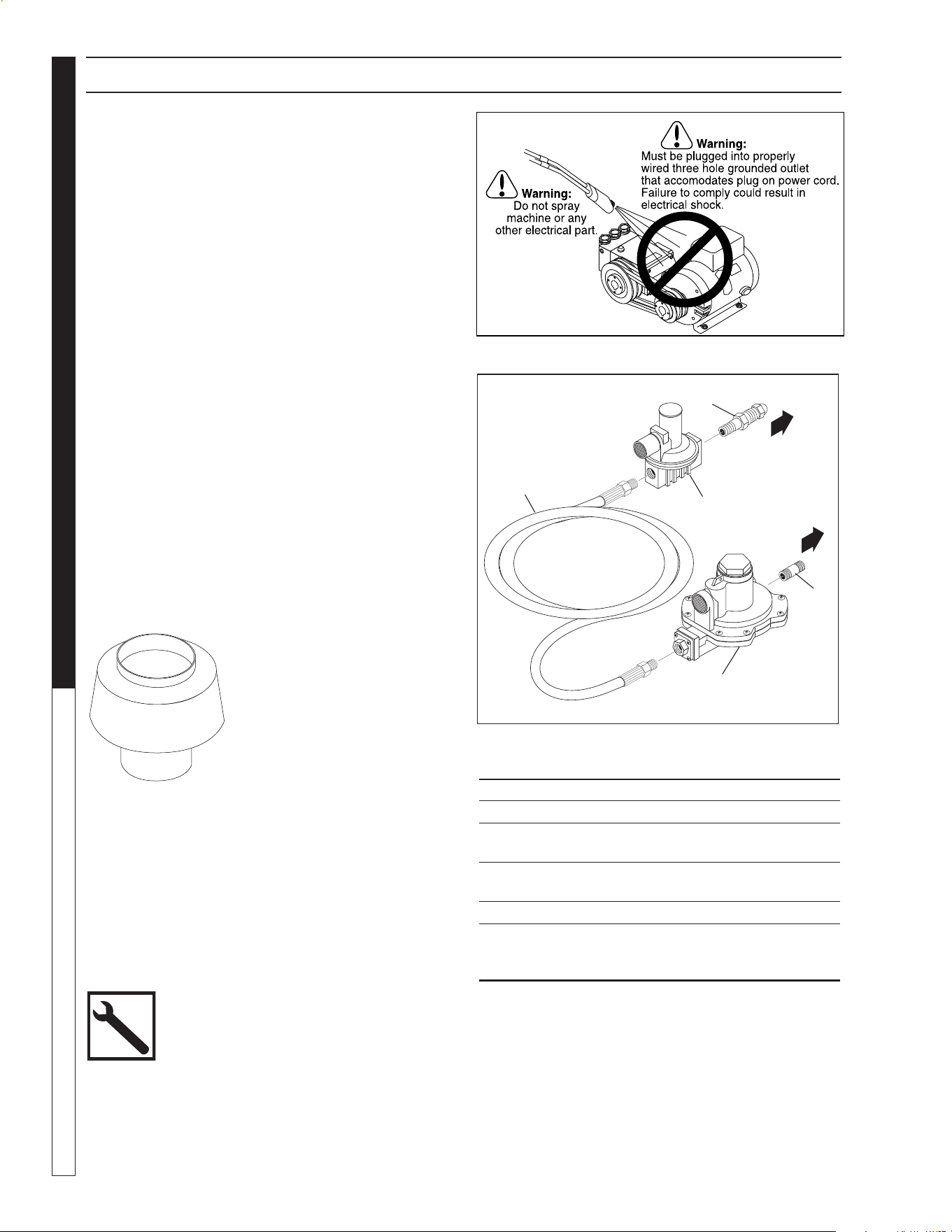
22. Install optional LP gas regulator assembly, item
9.802-633.0 or obtain a proper size regulator.
23. Install this machine about 2 feet from wall to
provide adequate ventilation and servicing space.
This equipment incorporates parts such as snap
switches or similar parts that tend to produce arcs
or sparks. Therefore, when located in a garage, it
should be in a room or enclosure provided for the
purpose or should be installed 18" (457mm) or
more above the floor.
WARNING: To reduce the risk of electric shock,
disconnect all electrical connections and shut-off
gas valve before servicing.
24. Install this machine on non combustible flooring.
25. Do not allow acids, caustic or abrasive fluids to
pass through the pump.
26. Never run pump dry or leave spray gun closed
longer than 3 minutes.
WARNING: If connection is made to potable water
supply, a back flow device must be provided.
27. Exhaust gases should not be vented into a wall, a
ceiling or a concealed space of a building. A draft
diverter must be installed to prevent down draft
and to allow cooling of exhaust temperatures.
Down draft diverters shall be installed in the vents
and located at a distance from
the pressure washer stack
to achieve maximum draft
of 36" minimum. Exhaust
gases that exceed 470°F
(243°C) are not suitable for
connection to Type B gas
vents.
Example of Down Draft Diverter for
Gas Fired Machines
28. Before disconnecting discharge hose from water
outlet, turn burner off and open spray gun to
allow water to cool below 100° before stopping
the machine. Then open the spray gun to relieve
pressure. Failure to properly cool down or maintain
the heating coil may result in a steam explosion.
Follow the maintenance instructions
specified in the manual.
ITEM PART NO. DESCRIPTION QTY
9.802-633.0 Regulator, LP Assembly 1
1 9.802-019.0 Nipple, 3/4" x 2", Black 1
2 8.717-747.0 Regulator, R622CFF for
R932/28 & R932462 1
3 8.717-746.0 Regulator, Hi Pressure,
R321H22 1
4 8.711-855.0 Hose, 1/2" x 19", Propane 1
5 8.717-782.0 Fitting, Pigtail, Fisher, M318
(Included when ordering part
8.717-746.0) 1
98016360-4
To Propane
Bottle
To Pressure Washer
Gas Inlet
1
3
5
2
4
Optional
Regulator Kit
9.802-633.0
9.801-637.0 - C • Kärcher Classic Operator's Manual
7
PRESSURE WASHER
MANUAL
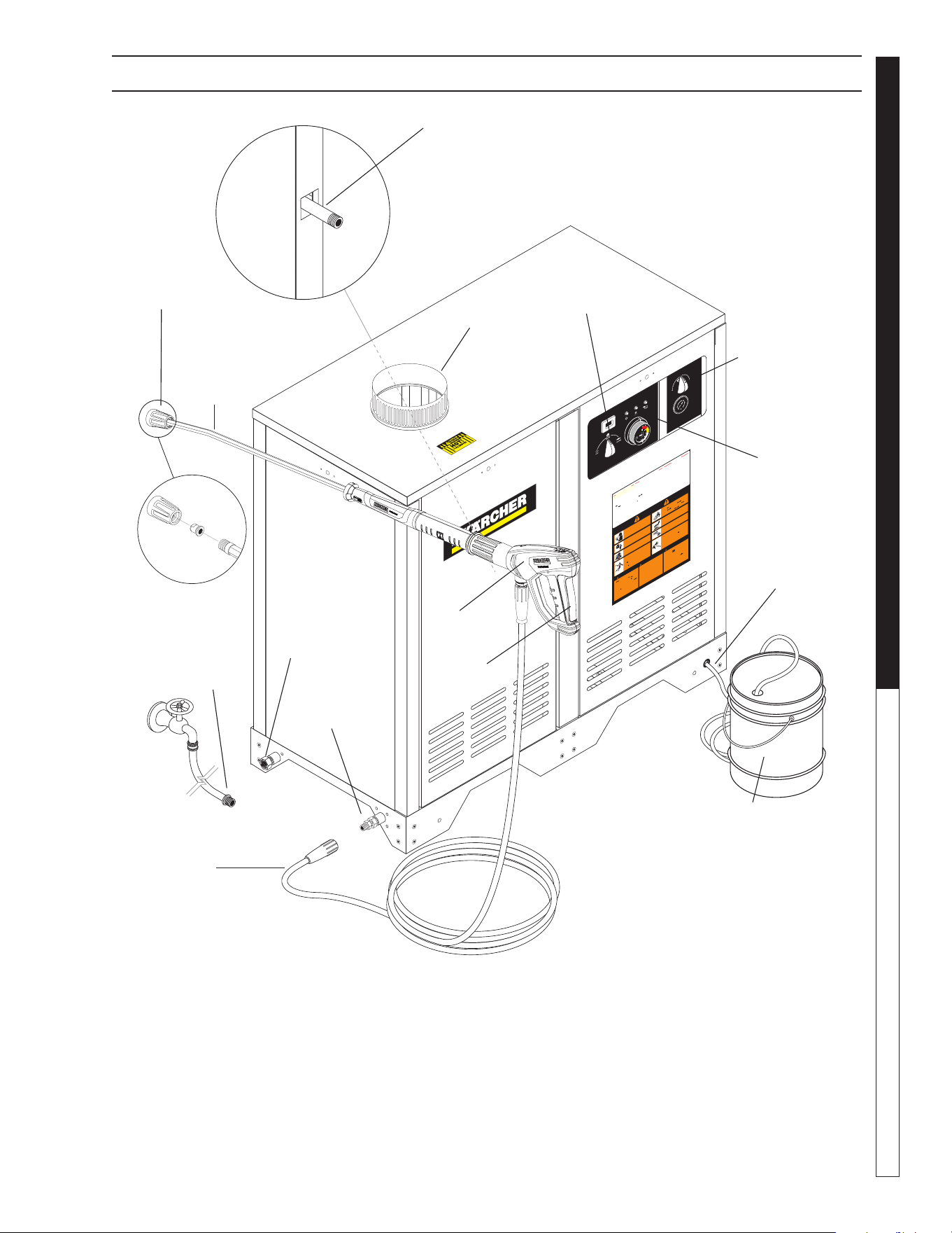
COMPONENT IDENTIFICATION - ALL MODELS
Pump — Delivers a specific gpm to the high pressure
nozzle which develops pressure. (Not Shown)
Spray Gun — Controls the application of water and
detergent onto cleaning surface with trigger device.
Includes safety latch.
Detergent Valve— Allows you to siphon and mix
detergents.
Wand — Must be connected to the spray gun.
High Pressure Hose — Connect one end to water
pump high pressure discharge nipple and the other
end to spray gun.
Rupture Disk — Secondary pressure release in the
unlikely event the unloader valve fails. (Not Shown)
Unloader Valve — Safety device which, when the
spray gun closes, prevents over pressurization. (Not
Shown)
98016360-2
GR
O
UND
8
10
1
2
1
4
16
0
2
4
6
TEMP
9
.80
1
-
63
3
.
0
T
ACH/HO
U
R
0
2
8
1
4
CH
EM%
9
.
8
01
-
63
4
.
0
50
200
250
3
0
0
3
1
5
1
0
0
150
0
1
.
Pl
a
ce a
l
l
s
witc
hes
in
th
e
“
O
F
F
”
pos
ition
.
2
.
C
onn
ec
t
po
w
e
r
sup
ply
to
pr
ope
rly
g
r
o
u
n
d
e
d
o
u
tle
t.
T
e
s
t
th
e
GFCI
(
i
f
eq
uipp
ed)
u
si
n
g
the
r
e
se
t
an
d
tes
t
pr
oced
u
r
e
s
provi
ded
o
n
the
G
F
CI
de
vi
ce
.
T
h
e
GFCI
m
u
st
be r
ese
t
an
d
tes
t
e
d
w
ith
e
very
us
e
.
3.
S
ec
ur
e
h
ig
h
pr
essu
r
e
hos
e
,
sh
u
t-
o
ff g
un
an
d
wa
n
d
to
out
-
let
4.
C
on
nect wa
t
e
r
sup
ply
h
ose
an
d
tur
n
on
wate
r
.
5.
Gra
sp w
and
P
l
ace
pu
m
p
s
witch in
th
e
“
O
N”
p
os
itio
n
.
6.
T
u
rn ga
s valve
co
ntro
l
knob
t
o
“
O
N”
po
s
ition
.
P
ilot
w
il
l
l
ight
auto
m
a
t
icall
y
w
he
n
b
u
r
ner
s
w
itch
i
s
t
urne
d
“O
N”
.
7
.
T
o
h
eat
w
a
ter
, pla
c
e
b
u
r
n
e
r
s
w
itc
h
i
n the
“
O
N”
pos
i
t
i
o
n
a
nd
ad
j
us
t
ther
m
o
stat
to
d
es
ir
e
d
t
em
p
era
ture
.
8.
Tu
r
n
on
deter
g
ent an
d
pr
ocee
d
w
i
t
h
cl
e
aning
.
9.
A
fte
r cl
ea
ning:
A
.
T
ur
n
off
det
e
r
g
en
t a
nd
ri
nse
.
B
. Plac
e
bu
r
n
er
sw
itc
h
in
t
h
e
“
OF
F
”
p
os
itio
n
.
C
.
A
l
lo
w
machi
n
e
to
dis
ch
ar
ge
w
a
ter
f
o
r
2
-3
mi
n
u
t
es to
cool co
i
l.
D.
P
l
a
ce
pum
p
swit
c
h
in the
“OF
F
”
p
os
itio
n
.
E
.
S
q
u
ee
z
e
trigg
er
g
u
n
t
o
r
e
lieve
sy
stem
pr
e
ssu
r
e
.
F.
T
urn off
w
a
te
r
su
p
ply
.
M
ODE D’
E
M
P
L
OI
L
IR
E
L
E
M
AN
U
E
L
D
E
L
’O
P
E
R
A
T
E
UR
AV
A
NT
U
T
IL
IS
A
T
ION
U
N
E
M
A
U
V
A
IS
E U
T
IL
ISA
T
IO
N
P
E
U
T
C
A
U
S
ER
D
E
S
B
L
E
S
SU
R
E
S
O
U
D
O
M
MA
G
E
S
MA
T
ÉR
IELS
.
I
NST
RUCCIO
NE
S DE OP
ERA
C
ION
L
E
A E
L
M
ANU
A
L
D
E
O
P
E
R
AC
I
Ó
N
A
NT
E
S
DE
U
S
AR
S
E
.
LA
O
P
ERA
C
I
Ó
N
I
NADE
C
U
A
DA
P
U
E
D
E
O
C
ASI
O
N
A
R
L
E
SI
O
N
E
S
P
ER
SO
N
AL
E
S
O
D
AÑ
O
S
A L
AS
P
R
O
P
IE
D
AD
E
S
.
O
PER
A
TIN
G
IN
S
TRU
C
T
IO
N
S
RE
A
D
O
P
ER
A
T
IN
G
M
A
N
U
A
L
B
E
F
ORE O
P
E
RA
T
I
N
G
M
AC
H
IN
E
.
IM
P
R
O
P
ER
O
P
ER
A
T
ION
MA
Y
R
E
SU
L
T
IN P
E
R
SO
N
A
L
IN
J
U
R
Y
OR
P
R
O
P
E
RT
Y
D
AM
AG
E
.
1. C
oloqu
e
todo
s
los
inter
r
uptor
es
en
la
po
s
ició
n
“OFF” (
A
P
A
GADO)
.
2. C
one
ct
e
la fu
ente
d
e
e
nergía
a
un
to
m
a
co
r
r
ient
e
con
ecta
d
o
a
t
ie
r
r
a
de
m
odo ad-
ec
ua
do
.
P
rue
b
e
el
I
nter
r
u
p
t
o
r
A
c
cionad
o p
or
C
orriente
d
e
Pé
rd
i
d
a
a
T
i
e
r
r
a
(
G
F
C
I
po
r
su
s
si
glas
en
I
ngl
é
s)
(
s
i
hub
i
er
a
) m
ed
ian
t
e
lo
s
pr
oced
i
mie
n
tos de
r
einici
o
y
pr
ueba
inc
o
r
p
o
rad
os
en
d
ic
ho dis
p
osi
tiv
o
.
E
l
G
F
CI
deb
e
r
ein
i
ci
a
r
s
e
y
po
n
erse
a
pr
ueba
cada
ve
z
q
u
e
se
use
.
3.
A
s
egu
re
l
a
ma
n
g
u
e
r
a
de
alta p
r
esió
n
,
p
is
tola
y
v
a
r
ill
a
a
l
acop
lado
r
d
el
tom
aco
r
-
r
i
e
n
te
.
4.
C
o
nect
e
la
m
a
n
gu
e
ra
de
suministr
o
de
ag
u
a
y ab
ra
la
llave
.
5.
S
u
j
ete
la
v
a
rill
a.
C
oloq
ue el inte
r
r
u
pto
r
de
la
b
om
ba
en
la
po
s
ició
n
“ON”
(
ENC
EN
DI
D
O)
.
6. C
o
loqu
e
la p
erill
a
de
cont
r
o
l
de
la válvula
d
e
gas
en
la
po
s
ició
n
“
ON
”
(
ENC
E
N
DI-
D
O)
.
El
pil
ot
o
se
encend
erá
aut
om
á
t
icament
e
cuand
o
e
l
que
m
a
dor s
e
en
c
iend
a
.
7.
A
de
ca
le
ntar el
a
gu
a
,
co
lo
que
el
in
terr
up
to
r
del
que
m
ad
o
r en
l
a
po
s
ició
n
“
ON”
(
ENC
E
N
DID
O)
y aju
ste e
l
te
rmo
s
tato
a
la
t
e
mp
e
r
a
t
u
r
a
d
es
ea
da.
8.
E
n
c
ienda
e
l
de
tergen
t
e
y
pro
ceda
co
n
la
li
m
pi
eza
.
9.
D
espu
és d
e
lim
pi
ar
:
A
.
A
pag
u
e
e
l
de
tergen
t
e
y
enju
ague
.
B.
Po
n
g
a
el
i
n
te
r
r
u
ptor
de
l
qu
em
a
dor
e
n
la
pos
ició
n
“
OFF”
(
A
P
A
GADO
)
.
C
.
D
ej
e que
la
máqu
i
n
a
d
es
ca
rgu
e
a
gua por
2
ó
3
m
in
u
to
s
p
a
r
a
qu
e
se
e
nfr
íe el
se
r
p
entí
n
.
D.
P
on
g
a el
int
e
r
ru
ptor
de
la
b
om
ba
en
la
po
s
ició
n
“OFF”
(
AP
A
GADO)
.
E
.
P
resio
ne la p
i
stola
p
ar
a
a
l
i
vi
a
r
la
pre
sión
de
l
si
st
em
a
.
F.
Cierre
el
sum
in
istr
o de
agu
a
.
1
.
Mette
z
tou
s
le
s
inte
r
r
u
pte
ur
s
e
n
p
os
itio
n
“
O
F
F”
.
2
.
C
o
nne
c
tez
le
b
l
o
c
d’a
lim
ent
ati
on
éle
ctri
que
à
u
ne
p
r
is
e
cor
r
e
c
temen
t
m
ise
à la
ter
re
.
T
e
s
te
z
l
e
disjoncte
ur
de
f
uit
e
de
te
rr
e
(
l
e cas
éché
ant
)
à
l’a
id
e de
s
pr
o
cédu
r
e
s
d
e
r
éinitia
l
isation
e
t
d
’essa
i
ind
iqué
es
s
u
r
le
dis
j
o
nc
te
ur
. L
e d
is
jo
nc
te
ur
d
o
it
êtr
e
r
é
initia
li
sé
et
te
s
té
à
c
ha
q
ue
u
til
i-
sa
t
ion.
3
.
F
i
x
ez
le
tu
y
a
u à
hau
te
p
re
ssi
on,
le
p
i
s
tolet
et le
t
ube
r
i
gide
au
r
a
c
c
o
r
d
de
sor
t
ie
.
4
.
C
onn
ec
te
z
le
tu
y
a
u
à
e
au
e
t f
a
ite
s
couler
l’ea
u.
5
.
Te
n
ez
le
tu
be
r
igide
f
e
r
m
e
men
t
.
M
e
tte
z
l
’in
te
r
r
u
pt
e
u
r
de
la
po
m
pe
en
po
s
ition
“
O
N”.
6.
Tour
ne
z
le
bou
ton
d
u
r
ob
inet
de
gaz
en
p
os
itio
n
“
ON
”.
L
a
veil
leuse
s’
a
l
lu
m
e
autom
a
t
ique
me
nt
lor
squ
e
l’i
nte
r
r
u
p
t
e
u
r
du
br
ûleur est
m
i
s
sur
“
ON”
.
7
.
P
o
ur
ch
a
uf
f
er
l’e
au
,
m
et
tez
l’i
nt
er
r
u
p
t
eur d
u
br
ûleu
r
su
r
“
O
N
”
e
t
r
é
glez
le
the
rm
o
stat
à
la
t
em
péra
t
u
r
e
v
ou
l
ue
.
8
.
A
cti
ve
z
le
dét
er
g
en
t et comm
en
c
ez
le
net
to
y
a
ge
.
9
.
A
pr
ès le n
e
tt
o
y
a
g
e
:
A
.
C
o
upe
z
le
d
éte
r
ge
nt et
r
i
nce
z.
B
.
M
e
t
t
e
z l’i
nte
r
r
u
pt
e
u
r
du
br
ûleur
su
r
“
O
FF”.
C.
L
ai
ssez
la m
achi
n
e év
acu
er l’ea
u p
en
dan
t
2
à
3
m
i
n
utes,
le
t
e
m
p
s q
u
e
la
b
ob
in
e
r
e
fr
o
i
d
i
sse
.
D
.
Mette
z
l’inte
r
r
u
pt
e
u
r
de
la
po
m
p
e
su
r
“
OF
F
”
.
E
.
Acti
on
nez
le
p
is
to
let
pou
r r
éduir
e
la p
ressi
o
n du
sy
stèm
e.
F
.
C
o
upe
z
l’e
au
.
WARNING
P
R
ECAUC
ION /
AVE
RTI
SSEM
ENT
T
O RE
D
U
C
E
T
H
E
R
ISK
OF
IN
J
U
R
Y
R
E
A
D
OPERA
T
OR
’S
M
AN
U
A
L
CAR
E
FU
LL
Y
BE
F
OR
E
USI
N
G.
T
H
IS
MAC
H
I
N
E
T
O
B
E
U
SE
D
ON
LY
B
Y
QU
AL
IFI
ED
OPE
R
A
T
ORS
.
L
E
A E
L
M
A
NU
A
L
O
P
ERAC
I
ON
A
N
TE
S
D
E
U
S
A
R
S
E
.
E
S
TE
E
QU
IPO
D
E
B
E
S
E
R
U
S
A
D
O
S
O
LA
M
EN
T
E
P
OR
OP
ERA-
D
OR
E
S
C
A
LI
F
I
C
A
D
OS
.
L
I
R
E
LE
M
A
N
U
E
L D
E
L
’
O
P
E
R
A
T
E
U
R
AV
A
N
T
U
T
I
L
ISA
TIO
N
.
C
E
T
A
P
P
A
R
E
I
L
D
O
I
T
ET
R
E
U
T
IL
I
SE
P
AR
DES
OP
E
RA
-
TE
U
R
S
Q
UA
L
I
FIE
S
.
R
I
S
K
OF
I
N
J
U
R
Y
—
P
R
O
T
E
CT
I
VE
E
Y
E
-
WE
A
R A
N
D
C
L
O
T
HI
N
G
MU
S
T
B
E
WORN.
w
h
en o
p
e
ra
t
ing
th
i
s
mach
ine
.
P
R
O
TEJ
A
S
E
LOS
O
J
O
S
CU
-
A
N
DO
se
o
pe
r
e
e
ste
e
qu
ipo
.
D
E
S
LUNETT
E
S
D
E
S
EC
U
R
ITE
D
O
IV
E
N
T
ETR
E
PORT
E
E
S
l
orsqu
e
vo
us
o
p
er
ez ce
t
app
a
r
eil.
R
I
S
K
O
F
A
SP
HYX
I
A
TI
ON
.
Use
o
n
l
y
i
n
we
ll
v
en
t
i-
l
a
t
e
d
ar
e
a.
R
I
E
S
GO
D
E
A
SF
I
X
IA.
U
se
e
l
p
r
oduc
t
o
e
n
u
n
a
r
ea
d
e
v
e
nti-
l
ac
ió
n
a
decu
a
da
.
R
I
SQ
U
E
D’A
S
PH
Y
XI
E
.
U
t
i
l
i
ser
d
an
s
u
n e
nd
r
o
i
t
b
i
e
n
aér
é
.
R
IS
K
O
F
E
L
E
CT
R
OC
UTI
ON
.
C
onn
ec
t
onl
y
t
o
pr
o
per
ly
g
r
oun
d
e
d
ou
tle
t
.
K
e
e
p
a
ll
c
on
-
ne
ction
s
d
ry and
off
t
h
e
gr
o
u
nd.
K
e
e
p
sp
r
a
y
a
w
ay
f
ro
m
e
l
e
c
t
r
i
c
a
l
w
i
r
i
ng and
c
o
mp
onen
ts.
Di
s
c
onnec
t
f
rom
ele
ct
r
i
c
a
l
s
u
pply
b
efo
r
e
serv
i
cin
g
.
R
I
E
S
G
O D
E
E
L
E
C
T
R
O
C
U
C
I
Ó
N
—
C
o-
n
ecte el
e
n
chu
f
e
en
u
n
co
n
ta
c
to
ad
e
c
u
a
d
o
.
Man
te
ng
a
t
o
d
as
l
a
s conn
e
cci
one
s
se
cas
y a
r
r
i
ba
d
el
su
e
lo.
N
o
r
o
cie
co
m
p
on
e
ntes
e
lé
ctr
i
co
s
.
D
e
scon
e
cte
la
co
r
r
i
en
t
e e
l
é
c
t
r
i
ca
a
ntes
d
e
d
ar
ser
vi
ci
o
.
R
IS
Q
U
E
D
’
E
LE
C
TR
O
C
UTIO
N
—
R
el
i
er
à
d
e
s
p
ri
se
s
a
v
e
c
m
i
se
à
l
a
t
e
r
re
se
ul
em
e
n
t
.
T
o
us l
es
d
o
ive
nt
ê
tr
e
m
a
i
nten
u
s se
cs
et é
tr
e
sus
-
p
en
du
s
.
N
o
j
amais
p
r
oje
t
e
r
d
e
l
’
e
a
u
su
r
l
es
co
m
-
p
osa
n
t
e
s
e
t
é
l
ec
t
r
i
ques
.
C
o
up
er
l
’
al
iment
a
t
atio
n
é
lec
tr
i
qu
e
av
a
nt
d
e
fai
r
e
u
ne
r
épa
r
ati
on
.
R
I
S
K
OF
I
N
JECTI
ON
O
R
S
E
-
V
ER
E
I
N
JU
RY
T
O
P
E
RS
ON
S
.
Kee
p
cl
e
a
r
of
no
z
zl
e
.
H
O
T
D
I
SC
H
A
R
G
E
F
L
U
ID
—D
o
no
t
t
ouc
h
or
d
i
r
e
c
t
discha
r
ge
s
t
r
e
a
m a
t
p
e
r
s
o
n
s.
R
IE
S
G
O DE
P
E
N
E
TR
AC
I
Ó
N
O
LE
S
I
O
N
E
S
S
E
V
E
R
A
S
A
P
E
R
S
O
-
N
A
S
.
M
a
n
t
é
ng
a
s
e
f
u
e
r
a
d
el a
lc
an
ce
d
e
b
oq
ui
l
l
a
.
D
E
S
CA
R
G
A
D
E
A
G
U
A
CALIE
N
TE
A
A
LT
A
P
R
E
S
I
ON
—
N
o
to
qu
e
n
i
d
i
ri
ja el
d
e
l
ag
u
a a otras
p
er
s
on
a
s
.
R
IS
Q
UE D
E
B
LE
S
S
U
R
E
S
.
S
e
ten
i
r
l
oi
n
d
es
b
u
se
s.
EA
U
C
H
A
U
D
E
S
OU
S
P
R
E
S
S
I
ON
A
LA
S
O
R
TIE
—
N
e
p
as dir
i
g
er
l
e
j
et
d
’e
a
u
ve
r
s de
s
p
e
r
so
nn
e
s.
S
P
RA
Y
GU
N
K
I
C
K
S
B
AC
K
—
H
o
l
d
w
ith
b
ot
h
ha
n
d
s
.
LA
P
I
S
T
OLA
S
E
M
U
E
V
E
C
O
N
L
A
P
R
E
S
IÓ
N
—
S
o
st
e
ng
a
co
n
l
as
d
os
m
a
no
s
.
LA
P
O
I
GN
E
E
P
I
S
TO
L
ET RE
-
P
OU
S
SE
—
T
e
ni
r
à
d
e
u
x
m
a
i
ns.
R
I
S
K
OF
I
NJU
RY
—
HOT
SUR
FA
CES
C
AN
C
A
U
S
E
B
U
RN
S
— U
s
e
o
nly
de
signed
g
r
ip
ping
are
a
s
of
spr
a
y g
un
a
n
d wan
d
.
S
U
P
ER
F
IC
IE
S
CA
L
I
E
N
TE
S
—
U
se
so
l
a
m
e
n
t
e
las
á
r
e
a
s
a
is
ladas
d
el g
atil
lo
y
l
a
l
an
za
.
S
U
R
F
A
C
E
S
C
H
AU
D
E
S
—
T
o
uch
e
r
se
ul
em
e
n
t
le
s
p
a
r
ti
es
i
so
lées
des
poi
g
né
e
pis
t
o
le
t
s
e
t
lan
ce
s.
R
IE
S
GO
D
E
E
XP
L
O
S
ION
—
U
se
e
l
p
r
od
ucto
e
n á
r
ea
s
d
onde
e
l
f
u
e
go
o
l
l
ama
se
an
p
e
r
m
i
ti
d
o
s.
N
o
r
o
ci
e
l
i
qui
do
s
R
IS
QU
E
D
’
E
X
P
LOS
I
ON
—
U
t
i
l
is
er
a
ux
e
nd
r
o
its
o
ù u
ne
nu
e
e
st
p
e
r
m
i
se
.
N
e
pas v
a
po
r
i
se
r
d
e
l
iqu
i
de
s
R
IS
K
OF
EX
P
L
OSI
ON
.
O
pe
r
a
t
e o
n
l
y
w
h
e
re
open
or
t
orch
is
p
er
m
itte
d
.
D
o
n
ot
s
p
ray
li
q
u
ids
.
R
IS
QUE
DE
FEU
OU
D
’E
XPL
OSION
RIE
SGO
DE INC
ENDI
O
O
EX
P
LOS
IÓN
R
I
SK
O
F FIR
E
O
R E
X
PLO
S
IO
N
•
M
a
c
h
in
e
need
s
t
o
b
e
in
s
ta
l
le
d
on
n
on
-combu
s
ti
ble
w
i
t
h
m
i
n
i
m
um c
l
ear
a
n
ce
o
f
1
8”
.
B
efor
e
l
i
g
h
t
i
n
g
,
s
me
l
l
al
l
a
r
o
u
n
d t
h
e app
l
ia
n
c
e
a
r
ea
f
o
r
ga
s
.
B
e
s
ur
e
t
o
s
m
ell
ne
xt t
o
th
e
b
eca
use s
o
me
g
a
s
i
s
h
e
a
vi
e
r
t
h
a
n
a
i
r
an
d
w
ill
s
ett
l
e
o
n
t
he
I
f
y
o
u
sme
l
l
ga
s,
im
medi
a
tely cal
l
your g
as
sup
p
li
er
for
i
nst
ruction
s
.
If
g
a
s
s
u
pp
l
ier
can
n
o
t
b
e
re
ach
ed
,
ca
l
l
th
e
depar
t
ment
.
D
o
n
ot
us
e
t
ools
t
o
p
us
h
i
n
or
t
u
r
n
the ga
s
cont
r
ol kno
b.
I
f
k
n
o
b w
ill
not
p
u
sh
in
o
r
tu
rn
b
y han
d
,
c
al
l
a
s
erv
i
c
e
t
ec
h
nici
a
n
.
U
s
ing
f
or
c
e
o
r
a
t
te
mp
t
i
n
g
r
e
p
ai
r
may
r
es
u
l
t
i
n
a
o
r
ex
pl
o
s
i
on.
S
h
o
u
ld
p
i
l
o
t
o
u
tag
e
oc
cur
,
t
ur
n
co
n
t
rol
k
no
b
t
o
O
F
F
p
o
si
ti
o
n.
W
a
it
5
m
in
ut
e
s
b
e
fore re
l
igh
t
ing
.
D
o
n
o
t
u
se t
h
i
s
e
q
uip
men
t
if
an
y
p
ar
t h
a
s
bee
n
und
e
r
w
a
t
e
r
.
I
mme
d
i
a
t
e
l
y
call
a
se
rv
ice
t
ec
h
nic
i
a
n
t
o
i
n
sp
e
c
t
f
o
r
r
e
p
a
i
r
.
E
l
e
quipo d
e
b
e
s
e
r
i
n
s
t
a
l
a
d
o
s
o
bre
u
n
p
i
so
r
esisten
te
al
i
n
ce
n
di
o
,
c
on
u
n
es
p
acio libr
e
d
e
1
8
”
mi
n
i
m
o.
A
n
tes d
e
ence
nde
r
,
olfat
ee
alr
e
d
e
dor
d
e
l
a
p
a
rat
o
pa
r
a
d
etec
t
ar
gas
.
E
s
t
é
s
e
gur
o
de
r
evis
a
r
ce
r
c
a
de
l p
is
o,
por
q
ue
c
ier
t
o
s
g
a
s
es
s
o
n
má
s
pes
a
dos qu
e
e
l
a
i
r
e. Si
olfa
t
ea
g
as
,
a
vi
s
e
i
n
m
ed
iata
me
n
t
e
a
s
u
p
r
o
v
e
e
d
or
de
ga
s
.
A
l
n
o
l
o
caliza
r
el
pro
v
e
e
do
r
,
llame
a
l
o
s
bomber
o
s.
N
o
use her
r
am
i
e
nt
a
s pa
r
a
mo
v
e
r
e
l co
n
tr
o
l
de
l
gas.
Si
l
a
m
an
ij
a n
o
se pue
d
e
o
p
e
rar
c
o
n
l
a
m
a
n
o,
l
l
a
m
e a
un
t
é
c
nico
capa
c
i
t
a
d
o.
Fo
r
z
a
r
o
i
n
t
e
n
t
ar
r
epar
a
r
e
s
t
e
co
n
tr
o
l
p
u
e
de
r
e
s
ult
ar
e
n
un
incendio o
e
xp
los
i
ón.
En el
c
a
s
o d
e
apagar
s
e
e
l
p
il
o
t
o
,
apa
g
u
e
y
e
sp
e
re
5
mi
n
ut
o
s a
n
t
es
d
e
e
n
ce
n
d
er
.
No u
t
i
l
ic
e
e
ste
equ
i
p
o
en
e
l
ca
s
o qu
e
hu
b
i
e
r
a
e
s
t
a
d
o
s
u
me
r
g
id
o
en
ag
ua
p
arc
ial
o
t
o
talm
en
te
un
co
m
p
o-
ne
n
te
.
Con
s
ulte
c
o
n u
n
t
é
cn
i
co
d
e
se
r
vi
c
io
.
N
e
pa
s
i
n
s
t
a
l
l
e
r
ce
mach
i
ne
a
u
x
e
n
dr
o
i
ts où
il
y
a d
e
s
comb
ust
i
b
l
es
(
m
ê
me
le
s
pl
anc
her
)
ded
an
s
u
n
d
em
i-
mètre
.
A
v
an
t
l’a
l
lu
mage,
a
u
to
u
r
d
e
l’
a
ppa
r
e
i
l
po
ur
des
se
n
t
eur
s de
g
az
.
le
s
o
de
u
rs prè
s d
u
p
l
a
n
ch
e
r
c
a
r
ce
r
t
a
i
n
s
g
a
z so
n
t
p
lus
l
o
u
r
d
s
que
l’
air
e
t
s’a
c
cumulen
t
s
ur
l
e
planche
r
. S
i
vou
s
dé
t
e
c
t
e
z
une odeur
d
e
gaz, a
pp
e
l
e
z
i
mm
é
di
ate
me
nt
v
o
t
re
fou
rnis
s
eu
r
d
e
g
a
z.
Si
c
elu
i
-ci
n
e
p
e
ut
être
join
t
,
ap
p
e
l
e
r
l
e
d
é
p
art
e
me
n
t de
s in
cend
i
e
s
.
Ne
p
as
ut
ili
ser
d
’
out
ils
p
o
ur
pouss
e
r
o
u
t
o
u
r
n
e
r
l
a
s
ou
p
a
pe
d
e
c
on
t
rô
l
e du
g
a
z
.
Si
la s
oup
a
pe
n
e
pe
u
t
êt
r
e
en
fon
cé
e
ou
tou
r
n
é
e
à
la
m
a
i
n, a
ppe
l
e
r
u
n
te
c
h
n
ic
i
e
n
Forcer
ou
es
s
ay
er
d
e
r
épa
re
r
peut
ca
us
er
u
n
f
e
u
o
u
une
ex
p
l
o
s
ion
.
S
i l
e
pi
lot
e
s’
éte
i
n
t
,
t
our
n
er
l
a
s
o
u
p
a
p
e
de
c
o
ntr
ôle
e
n
posi
t
i
on
OF
F
. A
t
t
end
re
5
m
i
n
u
te
s
avan
t
d
e
r
é
allume
r
.
N
e
p
as
ut
ili
s
er
c
e
t éq
u
i
p
e
m
e
nt
si
un
e p
art
ie
a
ét
é
i
mm
e
rgé
e
d
a
ns l’eau
.
A
pp
ele
r
u
n
tec
h
n
i
c
i
e
n
po
u
r
i
n
sp
e
c
t
er
ce
l
u
i
-
c
i
.
8
.
9
00
-
9
90
.
0
CHAUD!
Detergent
Valve
Spray
Gun
Spray
Wand
Trigger
High
Pressure
Nozzle
Exhaust
Collar
High Pressure
Hose
Water Supply
Hose
(not included)
Motor/Burner
Switch
Access
Panel
Detergent
Line
Hot Water
Discharge
Nipple
Water Inlet
Detergent
Bucket
(not included)
Gas Inlet located at
Rear of Machine
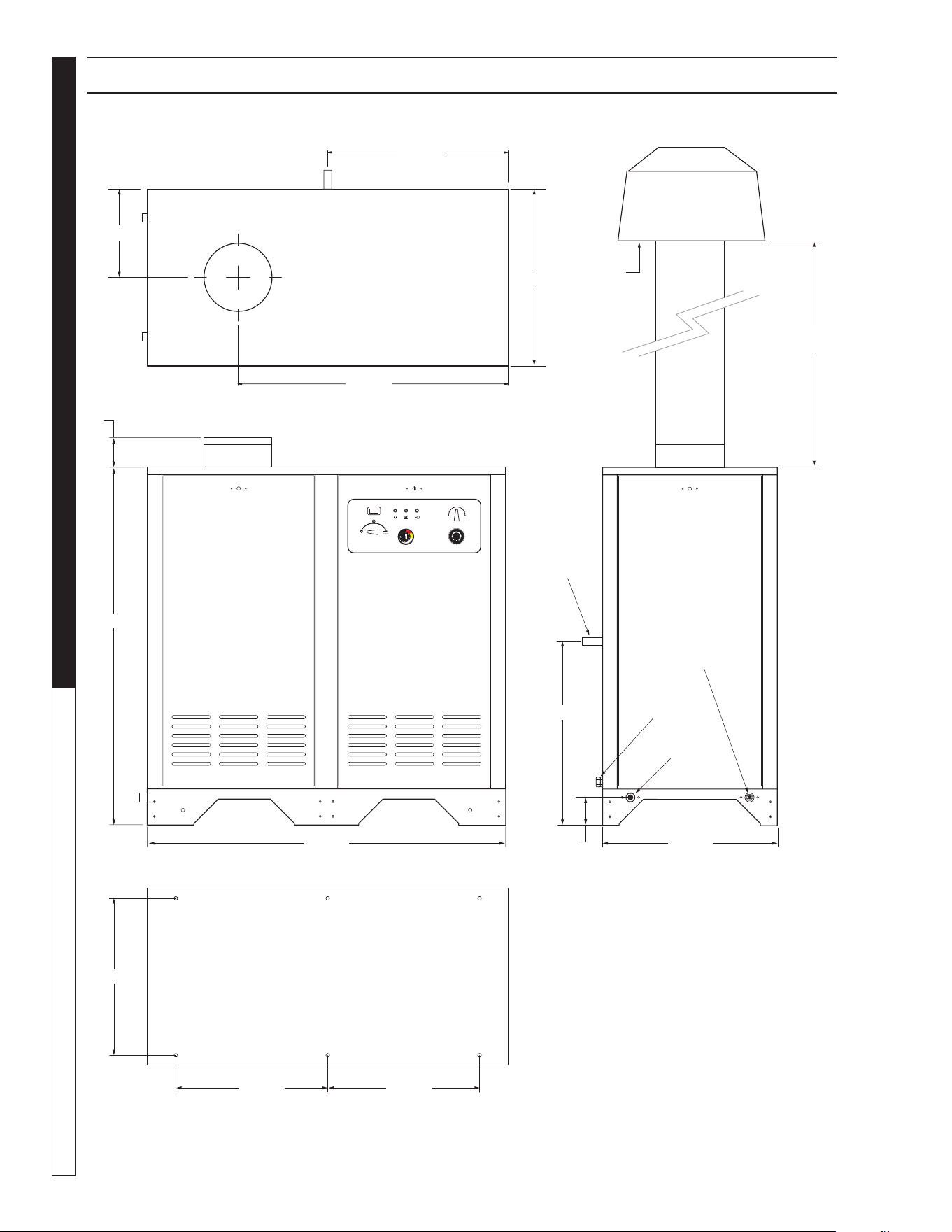
9.801-637.0 - C • Kärcher Classic Operator's Manual
MANUAL
PRESSURE WASHER
8
INSTALLATION HDS 3.5/30a, 4.5/22a, 5.0/30b, 50/30c
98016360-3
50
200
250
300
315
100
150
0
0
2
8
1
4
36.00"
Minimum
Control
Panel
19.50"
Dia.
Customer
Supplied Draft
Diverter
24.00"
24.87"
4.00"
High Pressure
Out 22mm
Screw
Connection
48.54"
36.68"
24.50"
24.00"
12.00"
49.00"
Water In
3/4" GHF
21.30"
20.61"
20.61"
Exhaust Out
10" Dia.
NOTE: Draft diverter should be
installed 3 ft. above exhaust outlet.
Piping to Outside
3.70"
Floor Mounting Dimensions
3/4" Gas
Inlet
Inlet
Electrical
Connection
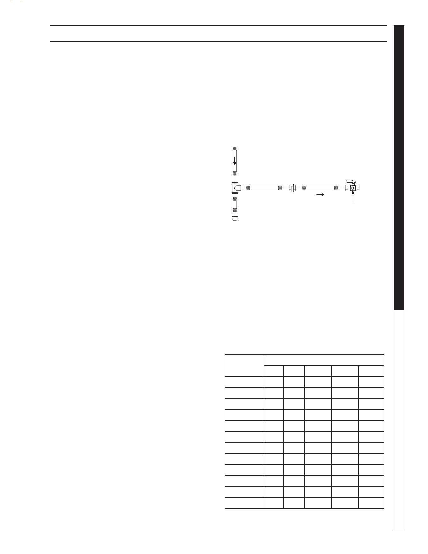
9.801-637.0 - C • Kärcher Classic Operator's Manual
9
PRESSURE WASHER
MANUAL
INSTALLATION
Install a gas union in the gas line adjacent to and up-
stream from the control manifold and downstream from
the manual main shut-off valve. A 1/8" NPT plugged
tapping accessible for test gauge connection shall
be installed immediately upstream of the gas supply
connection for the purpose of determining the gas
supply pressure to the burner, and to prevent damage
to gas valve.
If a manual gas shut off valve is not in the gas supply
line within six feet of the machine and in an accessible
location, one shall be installed.
Figure 1: Union Location
Union Connection
The following pipe sizes are just recommendations.
Always consult a local plumber and venting contrac-
tor for local codes and regulations during installation.
Pipe Sizing Chart for Natural Gas
The following chart is based on gas pressure in the
range 0-0.5 psi, specific gravity of 0.6 and pressure
loss of 0.5" W.C. Numbers are for straight schedule
40 pipe; fittings further reduce capacity. For example,
in 1" size, an elbow is equivalent to about 2.6 feet of
pipe and a tee is equivalent to about 5.2 feet of pipe.
Maximum capacity of pipe in cubic feet/hr of natural gas
(Multiply values by 1000 to get nominal BTU/hr capacity.
Place machine in a convenient location providing ample
support, drainage and room for maintenance (pgs 8-9).
Location:
The location should protect machine from damaging en-
vironmental conditions, such as wind, rain and freezing.
1. The machine should be run on a level surface
where it is not readily influenced by outside sourc-
es such as strong winds, freezing temperatures,
rain, etc. The machine should be located consider-
ing accessibility for the replacing of components
and the refilling of detergents, adjustments and
maintenance. Normal precautions should be taken
by the operator of the machine to prevent excess
moisture from reaching the machine.
2. It is recommended that a partition be made be-
tween the wash area and machine to prevent direct
spray from the spray gun from coming in contact
with the machine. Excess moisture reaching the
power unit or electrical controls will reduce the
machine’s life and may cause electrical shorts.
3. During installation of the machine, beware of
poorly ventilated locations or areas where exhaust
fans may cause an insufficient supply of oxygen.
Sufficient combustion can only be obtained when
there is a sufficient supply of oxygen available for
the amount of fuel being burned. If it is necessary
to install a machine in a poorly ventilated area, out-
side fresh air may have to be piped to the burner
and a fan installed to bring the air into the area.
4. Do not locate near any combustible material. Keep
all flammable material at least 20 feet away.
Allow enough space for servicing the machine.
Local code will require certain distances from floor
and walls. (Two feet away should be adequate).
WARNING: Avoid small areas or near exhaust fans.
Gas Codes:
Confer with local gas company and with proper mu-
nicipal officials regarding any specific code or regula-
tions governing the installation. The installation must
conform to local codes (NFPA 54).
Electrical:
The machine, when installed, must be electrically
grounded in accordance to local codes. Check for
proper power supply using a volt meter; check the
serial plate for the correct requirements.
Gas Piping:
This machine shall be rigidly connected to the gas pip-
ing outlet and equipped with external manual shut-off
valves adjacent to such machine. All gas piping shall
be approved and installed in accordance with the
Uniform Mechanical Code.
98015100-25
Manual
Shut-Off
Valve
1/8" NPT Plugged Pressure Gauge
Port Location
Union
Drop
Floor Level
Length of
Pipe (ft.)
Iron Pipe Size
3/4" 1" 1 -1/4" 1- 1/2" 2"
10 360 680 1400 2100 3950
20 250 465 950 1460 2750
30 200 375 770 1180 2200
40 170 320 660 990 1900
50 151 285 580 900 1680
60 138 260 530 810 1520
70 125 240 490 750 1400
80 118 220 460 690 1300
90 110 205 430 650 1220
100 103 195 400 620 1150
150 84 160 325 500 950
200 72 135 280 430 800

9.801-637.0 - C • Kärcher Classic Operator's Manual
MANUAL
PRESSURE WASHER
10
containers are equipped with a fixed liquid level gauge
which contacts the liquid level at 80% of container ca-
pacity, allowing 20% for expansion. LP-gas containers
not equipped with a fixed liquid level gauge can only
be filled by weight.
In cold climates, in order to keep vaporization of LP-
gas at the highest level, keep the fuel levels above
50%.
Room Vents for Combustion and
Ventilation Air
Properly sized vents are vital for the safe and efficient
operation of a pressure washer installed in a confined
space. When combustion and ventilation air are sup-
plied from inside the building, each opening must have
an area of one square inch for every 1,000 BTUH input.
When combustion air is supplied from the outside,
each opening must have an area of one square inch
for every 2,000 BTUH for horizontal ducts and one
square inch for every 4,000 BTUH for vertical ducts
(refer to NFPA 54). See Figure 3.
NOTE: Air vents for combustion and ventilation
and exhaust flue sizing must conform to methods
outlined in current American Standard (ANSI-
Z223.1), National Fuel Gas Code of National
Standard of Canada CSA-149.1 and CSA-149.2
“Installation Code for Gas Burner Appliances”.
Exhaust Stack
The purpose of venting a gas-fired pressure washer is
to completely remove all products of combustion and
to vent gasses to the outside air without condensa-
tion in the vent or spillage at the draft hood (except in
cases of downdraft or poor stack conditions). Always
use strong, gas-tight, insulated pipe.
The design of this pressure washer depends on natural
draft (heat induced) to pull combustion gasses out of
the combustion chamber. The design of the exhaust
stack can have a significant impact on the proper
operation of the burner and coil.
During vent installation, avoid sharp turns, long hori-
zontal runs and improper pitches. Maintain proper sup-
port of vent connectors and joints, observe clearances
from all combustibles and top the vent outlet with an
approved cap.
Type "B", due to its temperature rating, can only be
used with natural draft pressure washers. A "B" vent
is designed for exhaust temperatures not to exceed
470°F (245°C).
All venting installations must conform to local codes.
In the absence of local codes, refer to "National Fuel
Gas Code" NFPA 54 and be constructed of materials
approved by the Uniform Building Code.
Vents penetrating ceilings or walls should be double-
wall approved appliance vents and should be one to
INSTALLATION
LP-Gas (Liquid petroleum gas or
propane)
LP-gas is gas compressed into liquid form for easy
transportation and storage. It is also known as propane
or bottle gas. (Propane tanks are not supplied with
this equipment.)
LP-gas is flammable, is always contained under pres-
sure and the liquid can freeze skin. Therefore, in the
interest of safety, it is important to understand the basic
facts about LP-gas and LP-gas containers.
Federal DOT (Department of Transportation) regulations
require periodic inspections and re-qualifications of
cylinders. DO NOT USE damaged or rusted containers.
DO NOT store LP-gas containers indoors or in en-
closed areas. Do not expose LP-gas container to heat.
Always store with service valve closed and plugged
as required.
CAUTION: Use LP-gas containers in proper position.
Most LP-gas pressure washer heaters are designed
to operate on LP-gas vapor only. Therefore, all LP-
gas containers designed for vapor service must be
transported, installed and used in the proper position.
Do not transport, install or use a vertical cylinder in a
horizontal or upside down position. Proper care must
be taken to position a horizontal container in the cor-
rect position for vapor withdrawal. Liquid LP-gas could
enter the system designed for vapor only, possibly
creating a hazardous condition.
Always use a POL plug installed on a POL valve or a
dust cap on an ACME/Type 1 valve when transport-
ing or storing disconnected containers (full or empty).
Check for leaks after connecting. Apply approved leak
detector solution to connection, turn off all burners and
pilots and open service valve. Leaks will be detected
by the growth of bubbles. If bubbles grow, tighten or
repair the connection as needed. Repeat leak test until
problem is corrected.
Check all tank and the line connections periodically
to be sure they are tight. When testing for leaks, use
approved leak detector solution — not matches.
Improved Regulation: The second stage regulator
receives a relatively uniform pressure from the first
stage regulator. This helps the second stage regulator
to maintain appliance pressure at a nearly constant
11" W.C.
Filling the LP-Gas Container
Only qualified persons should fill your LP-gas
containers.
CAUTION: Overfilling is hazardous!
DO NOT allow your LP-gas container to be overfilled.
Stop filling when liquid appears at the fixed level gauge.
Bleed off excess propane in a safe area. Most LP-gas
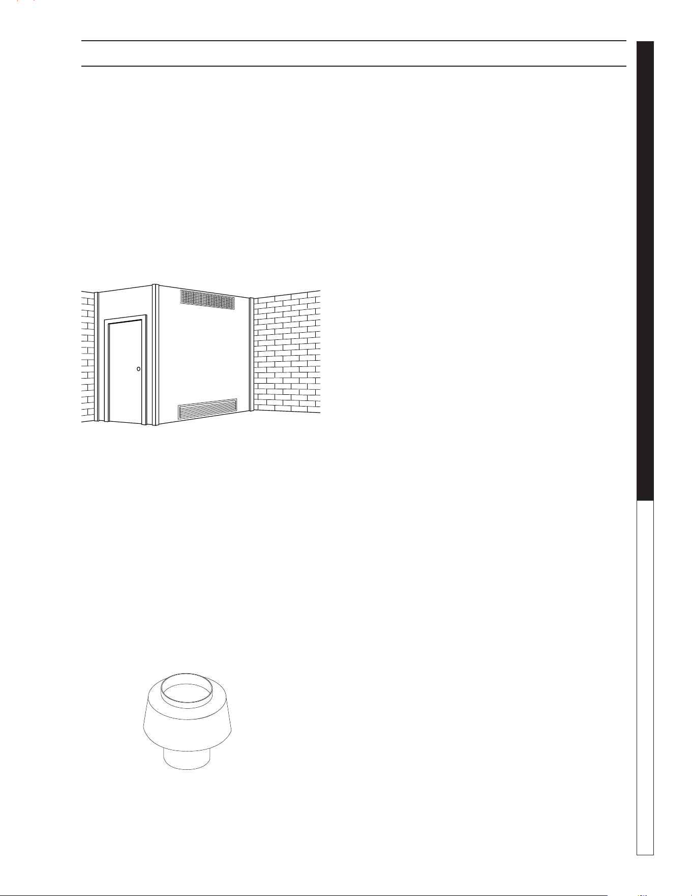
9.801-637.0 - C • Kärcher Classic Operator's Manual
11
PRESSURE WASHER
MANUAL
two inches from combustibles. Vents passing through
enclosed spaces and vents exposed to the weather
should also be the double-wall type. Sometimes vents
have to be built of such great length that they come
apart at their joints under their own weight. These
should be screwed together at the joints with sheet
metal screws, usually three per joint. If the inspector
indicates that the vent is too close to combustibles, it
may be necessary to chisel away some of the com-
bustible or route the vent pipe around the combustible.
The cross-sectional area of any flue shall not be less
that the cross-sectional area of the flue vent connec-
tion outlet of machine.
The pressure washer includes a collar that will mate
with standard HVAC ducting. The user will be respon-
sible for installation of an exhaust stack. The exhaust
stack should include a Draft Diverter/Inducer, Damper,
Sampling Port and Rain Cap. An adapter can be
installed between the collar and stack to adjust the
diameter from 10” to 8” or 12” to 10”.
Size the stack according to the following (see also
applicable local and national standards regarding
installation of gas-fired appliances):
• 3.5 to 4.5 gpm 10” Collar 8” Stack
• 5.0 gpm 10” Collar 10” Stack
(Figure 4)
Draft Diverter/Hood: The draft required to vent
combustion gases is created by the heat inside the
pressure washer coil. A draft diverter helps improve
draft into the stack without pulling more air through the
combustion box and decreasing combustion efficiency.
The draft diverter can also help prevent back drafting
that can inhibit combustion. The draft diverter should
be installed a minimum of 36” above the flue collar.
See Figure 4.
Power Vent (Draft Inducer): If this machine is going
to be installed on a 90° or extended exhaust vent run
length which may restrict air flow it is recommended
that a contractor install a power vent. When a contrac-
tor has found it impossible to vent straight through the
roof power venting is recommended to help eliminate
exhaust restriction of this natural draft machine. This
draft inducer (power vent) must be installed by a li-
censed contractor who can calculate size, operation
connections and associated dampeners. Since we
are a manufacturer and not a licensed contractor and
as such we are unable to make recommendations for
suitable make and model of power vents and compli-
ance with local building codes.
Damper: An exhaust stack can reduce thermal ef-
ficiency by drawing in too much combustion air. This
can be controlled by adding a damper just below the
draft diverter. 8.753-473.0 - 8" Damper, 8.753-474.0
-10" Damper, 8.753-418.0 - 12" Damper.
NOTE: Closing the damper can create high levels of
CO in the exhaust. Adjustments to the damper should
only be performed by a trained technician using a flue
gas analyzer. If an analyzer is not used the damper
should be set in the fully open position.
Sampling Port: A port for sampling flue gases and
measuring the flue gas temperature should be placed
18” above the flue collar. The port should be covered
when sampling is not being performed. The size of
the port should be only slightly larger than the probe
for the flue gas analyzer.
Rain Cap: A rain cap should be installed on top of
the stack to prevent rain water, leaves and debris from
entering the stack. Your installer may also recommend
specialty caps for high wind areas or cold weather
zones to help prevent back drafting. 8.717-731.0 - 10"
Raincap, 8.717-732.0 - 12" Raincap
Water Source:
The water source for the machine should be supplied
by a 5/8" I.D. garden hose with a city water pressure of
not less than 30 PSI. If the water supply is inadequate,
or if the garden hose is kinked, the machine will run
very rough and the burner will not fire.
Water Connection:
Connect the high pressure hose by pulling the coupler
collar back and then inserting it onto the discharge
nipple. Secure it by pushing the collar forward.
Attach the wand into the spray gun using teflon tape
on the pipe threads to avoid leaks.
INSTALLATION
Illustration showing air openings necessary
to supply air for combustion when installed
in an enclosed room.
Figure 3: Ventilation
Draft Diverter
Required
8.717-728.0 8"
9.801-040.0 10"
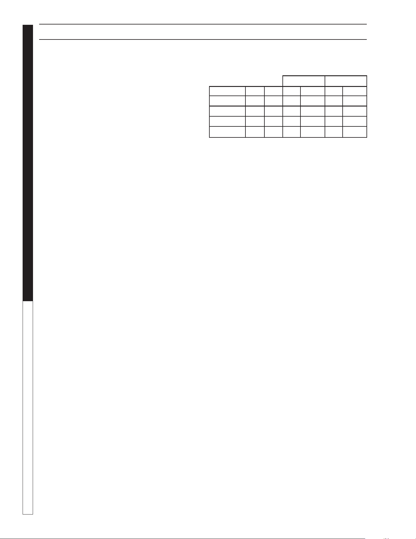
9.801-637.0 - C • Kärcher Classic Operator's Manual
MANUAL
PRESSURE WASHER
12
Inspection and Testing Gas Piping:
The building structure should not be weakened by
installing the gas piping. The piping should not be
supported by other piping, but should be firmly sup-
ported with gas hooks, straps, bands or hangers. Butt
or lap welded pipe should not be run through or in an
air duct or clothes chute.
Before turning gas under pressure into piping, all open-
ings from which gas can escape should be closed.
Immediately after turning on gas, the system should
be checked for leaks. This can be done by watching the
1/2 cubic foot test dial for 5 minutes for any movement
or by soaping each pipe connection and watching for
bubbles. If a leak is found, make the necessary repairs
and repeat the above test.
Defective pipes or fittings should be replaced and not
repaired. Never use a flame or fire in any form to locate
gas leaks — use a soap solution.
After the piping and meter have been checked com-
pletely, purge the system of air. DO NOT bleed the air
inside an enclosed room.
During pressure testing of the system at test pressures
in excess of 1/2 PSIG, the pressure washer and its
individual shut-off valve must be disconnected from
gas supply piping system or damage to the gas valve
will occur.
Gas Pressure:
The incoming gas pressure must be a minimum of
9.0 wc-in and must not exceed 13.8 wc-in or ½ psig
to the control valve. Line pressure above ½ psig must
be regulated prior to the machine. The ideal supply
pressure is 13.0-13.5 wc-in. If the required BTU input
can not be achieved consult the factory for instructions
regarding changes to the nozzle orifice size and an
appropriate manifold setting.
NOTE: Any changes to the burner and manifold pres-
sure setting should only be performed by a trained
technician and adjusted using a flue gas analyzer.
The manifold pressure has been preset at the factory
according to the table below for optimum operation at
sea-level. The manifold pressure and BTU input will
be listed on the specification plate for the machine.
For Tech Tip Instructions
Combustion efficiency in a natural draft pressure
washer is significantly influenced by the heat created
inside the coil, the design of the coil and flue and the
length and diameter of the exhaust stack. The table
below shows data included in the operator’s manual
for flue and stack sizes and gas manifold pressure
settings. These sizes are critical for achieving proper
combustion and acceptable emissions.
Testing has shown that simply adding a 36” stack
extension to the flue adapter on top of the pressure
washer can reduce the outlet temperature by 5-10°F.
This occurs by inducing a higher pressure differential
at the exit of the coil and increasing the flow of air into
the combustion process and through the stack. Most
or all of the lost outlet temperature can be recovered
by installing and adjusting a damper in the stack.
However this adjustment must only be performed by
a trained technician using a combustion analyzer. An
adequate combustion analyzer can be purchased for
a little at $500 (Bacharach Fyrite Tech, Testo 310).
The analyzer must determine percent oxygen and/or
percent excess air as a minimum.
The damper should be installed 24-36” above the flue
adapter. The pressure washer can be operated safely
with the damper fully open but with the lower outlet
temperature. If the damper is closed too far there will
not be enough oxygen to burn all of the fuel. This will
cause higher and potentially dangerous levels of CO
in the flue gas emissions.
To adjust the damper for proper combustion and ef-
ficiency perform the following:
1. If there is no sample port for the analyzer probe,
drill a hole slightly larger than the combustion
analyzer probe through the exhaust stack at a
point about 18” above the flue adapter.
2. Insert the probe of the combustion analyzer so
that the tip is at the center of the stack.
3. Open the damper to the fully open position.
4. Start the pressure washer and allow it to heat up
for at least 20 minutes before making any adjust-
ments.
5. Note the values for % Excess Air and/or % Oxygen.
6. Close the damper in small increments until %
Excess Air is between 20-30% and/or % Oxygen
is 4-5%.
INSTALLATION
NG LP
Model Collar Stack wc-in kBTU-in wc-in kBTU-in
3.5@3000 10" 8" 3.4 310 7.4 310
4.5@2200 10" 10" 3.1 393 8.6 393
5.0@3000b 10" 10" 4.8 398 9.9 398
5.0@3000c 10" 10" 4.8 398 9.9 398

9.801-637.0 - C • Kärcher Classic Operator's Manual
13
PRESSURE WASHER
MANUAL
INSTALLATION
This process can also be used when turning down the
firing rate for high altitude installations above 2000 ft.
1. Adjust the gas pressure down 4% for every 1000
ft of elevation.
Example: Recommended firing rate for a 4.8@3000
is 4.2 wc-in. For an installation at 3500 feet reduce
this pressure by 16% by setting the manifold pressure
to 4.2*.84 = 3.5 wc-in.
A manometer capable of reading to at least the nearest
0.1 wc-in will be required for this adjustment. These
can be found for less than $200 (Extech HD700).
2. Follow steps 1-6 above to optimize the outlet
temperature of the pressure washer.
Installations Above 2000 ft:
Installation at altitudes greater than 2000 ft will require
adjustments to the gas manifold pressure.
For installations above 2000 feet the firing rate should
be reduced by 4% per 1000 feet. Example: Recom-
mended firing rate for a 4.8@3000 is 4.2 wc-in. For an
installation at 3500 feet reduce this pressure by 16%
by setting the manifold pressure to 4.2*.84 = 3.5 wc-in.
This adjustment should only be made by a properly
trained service technician. A manometer capable of
reading to the nearest 0.1 wc-in will be required for
this adjustment.
In Canada, certification for installation at altitudes over
4500 feet is the jurisdiction of local authorities.
Gas Valve Replacement:
If you replace your gas valve the manifold pressure
for the new valve will need to be adjusted to match
the specification plate for the machine. Follow the
installation and adjustment instructions provided with
your replacement valve. A manometer capable of
reading to the nearest 0.1 wc-in will be required for
this adjustment.
CAUTION: All gas conversion must be done by a
qualified service person in accordance with these
instructions and in compliance with all codes and
requirements. In Canada, gas conversion shall be
carried out in accordance with requirements of
the Provincial Authorities having jurisdiction and
in accordance with the requirements of the CAN/
GGA-B149.1 and .2 installation code.
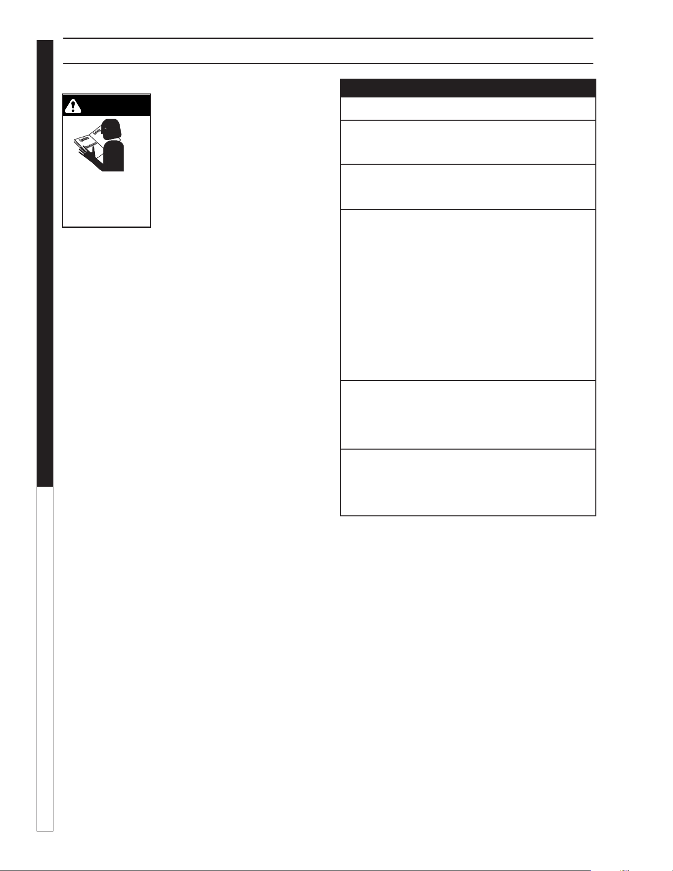
9.801-637.0 - C • Kärcher Classic Operator's Manual
MANUAL
PRESSURE WASHER
14
WARNING
read safety
instructions prior
to installing or
servicing machine.
INSTALLATION
FOR YOUR SAFETY READ BEFORE LIGHTING
WARNING
If you do not follow these instructions exactly, a fire or
explosion may result, causing property damage, per-
sonal injury or loss of life.
A. This appliance has a pilot which must be lighted by
hand. When lighting the pilot, follow these instructions
exactly.
B. BEFORE LIGHTING smell all around the appliance
area for gas. Be sure to smell next to the floor because
some gas is heavier than air and will settle on the floor.
"FOR YOUR SAFETY
"WHAT TO DO IF YOU SMELL GAS"
• Do not try to light any appliance.
• Do not touch any electrical switch, do not use
any phone in your building.
• Immediately call your gas supplier from a neighbor's
phone. Follow the gas supplier's instructions.
• If you cannot reach your supplier, call the fire dept.
C. Use only your hand to push in or turn the gas control
knob. Never use tools. If the knob will not push in or turn
by hand, don't try to repair it; call a qualified service
technician. Forced or attempted repair may result in a
fire or explosion.
D. Do not use this appliance if any part has been under
water. Immediately call a qualified service technician
to inspect the appliance and to replace any part of the
control system and any gas control which has been
under water.
START-UP
WARNING: Read and follow
instructions carefully when
installing or servicing machine.
Failure to do so may result in
damage to property or personal
injury.
1. Installation or servicing of gas
appliances and controls must
only be performed by quali-
fied personnel. After install -
ation or servicing, test the manual valve, operating
valves, pressure regulation, and automatic shut-off
valve for proper operation.
2. Install in a suitable dry location. Machine must
be located in an area properly protected from
weather.
3. Shut off gas and electricity before starting instal-
lation or service. Turn back on to test or operate.
4. DO NOT connect machine before pressure testing
the gas piping. Damage to gas valve may result.
(9" - 14" W.C.P. or 1/2 PSIG)
5. DO NOT insert any object other than suitable pipe
or tubing in the inlet or outlet of the gas valve. Inter-
nal damage may occur and result in a hazardous
condition.
6. DO NOT short the gas valve terminals.
7. DO NOT grip gas valve body with a pipe wrench
or vise. Damage may result causing gas leak
age.
Use inlet or outlet bosses or a special body wrench.
8. DO NOT allow any flame to impinge on the regula-
tor vent tubing if supplied. It may clog and cause
gas valve malfunction.
9. DO NOT use the gas cock to adjust gas flow.
10. If main burner fails to shut off, turn off gas supply.
11. Keep all combustible materials away from gas
appliances. DO NOT allow lint or dust to collect
in burner area.
12. Dials must only be operated by hand. Never use
pliers, wrenches or other tools to turn dials.
13. Leak test with a soap solution after installation or
service with the main burner on. Coat pipe and
tubing joints, gaskets, etc.

9.801-637.0 - C • Kärcher Classic Operator's Manual
15
PRESSURE WASHER
MANUAL
INSTALLATION
YES NO
Has gas supply been inspected by an
authorized contractor to meet local
codes?
Is machine protected from downdraft
and excessive wind?
Is machine shielded from moisture or
water spray?
Is the voltage correct and are the
circuit breaker and supply cord
adequate according to specifications
and serial plate notation?
Is the machine electrically grounded?
Is there ample water supply?
Have all flammable liquids or gases
been removed from installation loca-
tion?
Is there adequate gas supply for the
BTU rating of the burner?
"Is incoming gas supply pressure
between 6" - 14" water column inches
or 1/2 PSIG?"
Has the proper gas regulator been
installed for pressure and volume?
Have you installed the optional LP
gas regulator assembly 9.802-633.0?
Is the machine properly vented to
allow adequate air flow?
Are the propane tanks large enough,
according to rating to prevent freez-
ing?
Have gas lines been checked for gas
leaks?
Have gas lines been checked with
local codes?
Have all operators using this machine
been instructed properly and have
they read the manual?
Has the machine been installed
according to operator's manual
instructions?
Check List Before Starting:
CAUTION! If “NO” has been checked on any of the
following sixteen questions, do not operate this
machine.
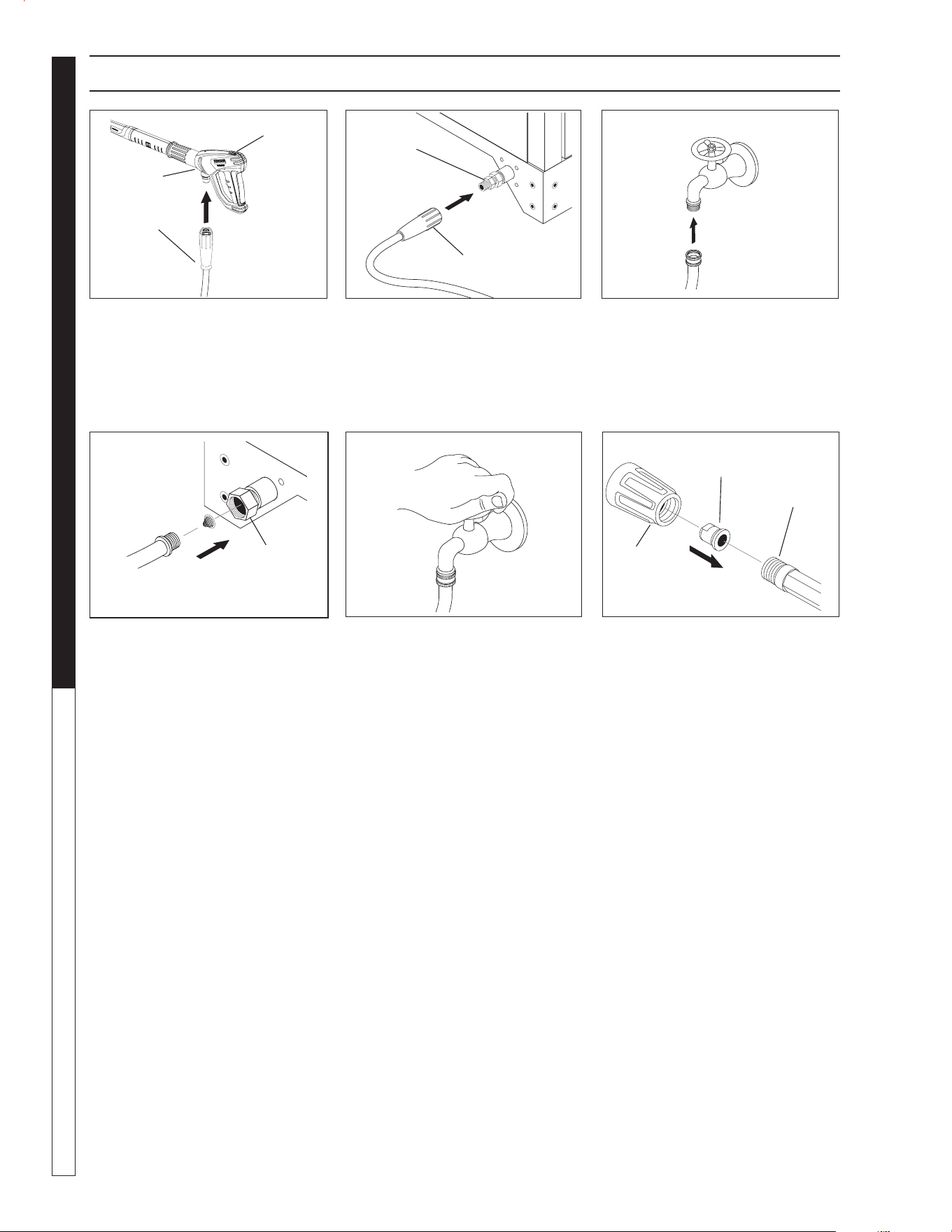
9.801-637.0 - C • Kärcher Classic Operator's Manual
MANUAL
PRESSURE WASHER
16
98015080-6
98016360-5
ASSEMBLY INSTRUCTIONS
STEP 1: Attach the high pressure
hose to the spray gun using teflon
tape on hose threads.
STEP 4: Connect the garden hose
to pump water inlet. Inspect inlets.
CAUTION: Do not run the pump
without water or pump damage
will result.
Safety
Latch
Spray
Gun
High Pressure
Hose
98016360-7
STEP 3: Connect garden hose to
the cold water source.
Cold
Water
Source
Garden
Hose
98016360-10
STEP 6: Attach the Power Nozzle
to end of the wand as shown in
picture.
Pressure
Nozzle
Wand
Guard
STEP 2: Connect the high pressure
hose to the discharge fitting. Push
coupler collar forward until secure.
Pump
Discharge
Fitting
STEP 5: Before installing nozzle,
turn on the water supply and run
machine allowing water to run from
the end of the wand until clear. Turn
off machine.
98016360-9
High
Pressure
Hose
98015100-8
98016360-8
Pump
Water Inlet
Garden
Hose
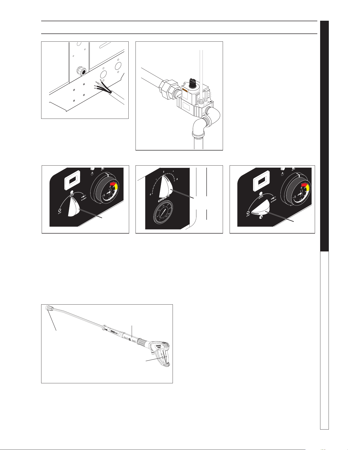
9.801-637.0 - C • Kärcher Classic Operator's Manual
17
PRESSURE WASHER
MANUAL
OPERATING INSTRUCTIONS
STEP 1: Have an electrician con-
nect power supply into electrical box
according to information shown on
the serial plate.
98016360-12
STEP 2: Turn on main gas supply
and depress and turn control knob
to the ‘ON’ position.
OFF
ON
98016360-13
STEP 3: Turn switch to "MOTOR"
position and pull the trigger on the
spray gun allowing cold water to
flow. To activate the gas control
valve for hot water, rotate switch
to the "BURNER" position and pull
the trigger on the spray gun.
STEP 4: To apply detergent open
the detergent valve clockwise mak-
ing sure that the detergent pick-up
tube is in the detergent solution and
not sucking air.
98016360-17
NOTE: High pressure nozzle must be attached at
end of wand to obtain high pressure. To apply soap,
see page 20.
Trigger
Wand
High
Pressure
Nozzle
STEP 5: To Stop: Turn the burner/
motor switch to "MOTOR" and
place the detergent pick-up tube
into fresh water. Open the detergent
valve and trigger spray gun allowing
detergent lines to be flushed and
the burner to cool. Otherwise, coil
damage will result.
After water has cooled, turn
switch to "STOP" position. If the
machine is going to be off for an
extended period of time, put the
manual valve on the gas valve into
the "OFF" position.
Turn the water off. Protect
from freezing.
9.801-
6
TACH/HOUR
98016360-14
Burner/
Motor
Switch
9.801-634.0
98016360-15
Detergent
Valve
TACH/HOUR
98016360-16
Burner/
Motor
Switch
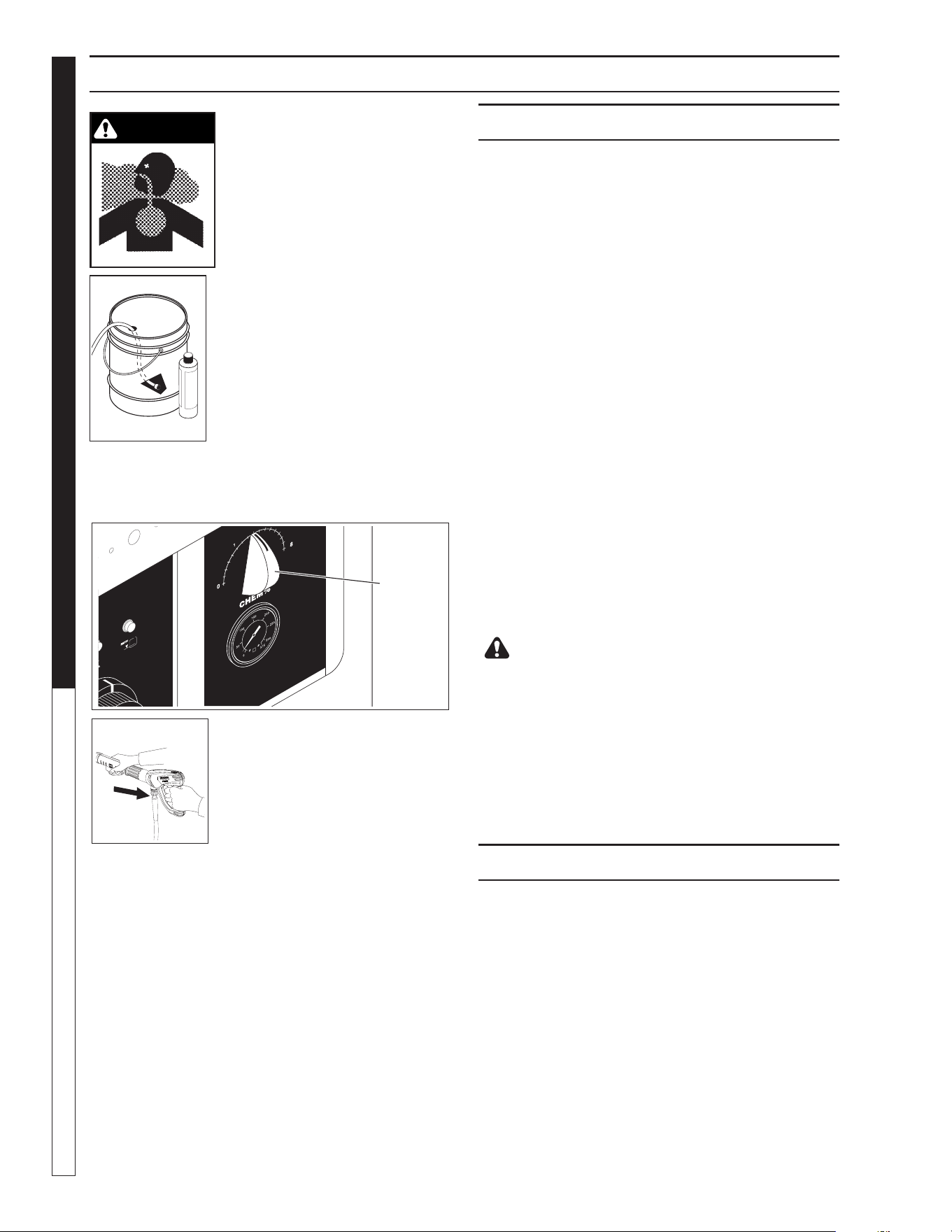
9.801-637.0 - C • Kärcher Classic Operator's Manual
MANUAL
PRESSURE WASHER
18
WARNING: Some detergents
may be harmful if inhaled
or ingested, causing severe
nausea, fainting or poisoning.
The harmful elements may
cause property damage or
severe injury.
STEP 1: Use detergent designed
specifically for pressure wash-
ers. Household detergents could
damage the pump. Prepare de-
tergent solution as required by
the manufacturer. Fill a container
with pressure washer detergent.
Place the filter end of detergent
suction tube into the detergent
container.
STEP 2: Open detergent valve counterclockwise
until you obtain desired mixture. Detergent will mix
with the high pressure water stream.
STEP 3: With the motor running,
pull trigger to operate machine.
Liquid detergent is drawn into
the machine and mixed with
water. Apply detergent to work
area. Do not allow detergent to
dry on surface.
IMPORTANT: You must flush the detergent from
your pressure washer after each use by placing
the suction tube into a bucket of clean water,
then run the pressure washer for 1-2 minutes.
NOTE: If you remove detergent siphon tube from
container or allow container to empty, it will cause
low pressure by sucking air, which will damage
the pump.
CLEANING TIPS
Pre-rinse cleaning surface with fresh water. Place
detergent suction tube directly into cleaning solu-
tion and apply to surface. For best results, limit your
work area to sections approximately 6 feet square
and always apply detergent from bottom to top. Allow
detergent to remain on surface 1-3 minutes. Do not
allow detergent to dry on surface. If surface appears
to be drying, simply wet down surface with fresh water.
If needed, use brush to remove stubborn dirt. Rinse at
high pressure from top to bottom in an even sweeping
motion keeping the spray nozzle approximately 1 foot
from cleaning surface. Use overlapping strokes as you
clean and rinse any surface. For best surface cleaning
action spray at a slight angle.
Recommendations:
• Before cleaning any surface, an inconspicuous
area should be cleaned to test spray pattern and
distance for maximum cleaning results.
• If painted surfaces are peeling or chipping,
use extreme caution as pressure washer may
remove the loose paint from the surface.
• Keep the spray nozzle a safe distance from the
surface you plan to clean. High pressure wash a
small area, then check the surface for damage. If
no damage is found, continue to pressure washing.
CAUTION - Never use:
• Bleach, chlorine products and other corrosive
chemicals
• Liquids containing solvents (i.e., paint thinner,
gasoline, oils)
• Tri-sodium phosphate products
• Ammonia products
• Acid-based products
These chemicals will harm the machine and will
damage the surface being cleaned.
RINSING
Turn detergent valve counter clockwise to close. Oper-
ate pressure washer and allow a few seconds for the
detergent to clear.
WARNING
APPLYING DETERGENT & GENERAL OPERATING TECHNIQUES
2
9.801-634.0
98016360-19
Detergent
Valve
98016360-18
98016360-20
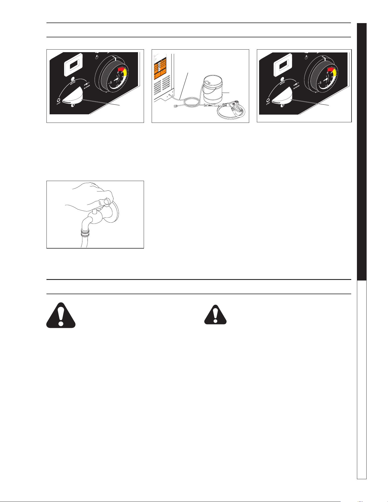
9.801-637.0 - C • Kärcher Classic Operator's Manual
19
PRESSURE WASHER
MANUAL
CAUTION: Failure to follow the above
directions will result in damage to your
pressure washer.
After Extended Storage
CAUTION: Prior to restarting, thaw out any
possible ice from pressure washer hoses, spray
gun or wand.
SHUTTING DOWN AND CLEANUP
STORAGE
CAUTION: Always store your pressure
washer in a location where the temper-
ature will not fall below 32°F (0°C). The
pump in this machine is susceptible to
permanent damage if frozen. FREEZE DAMAGE
IS NOT COVERED BY WARRANTY.
1. Stop the pressure washer, squeeze spray gun
trigger to release pressure.
2. Detach water supply hose and high pressure
hose.
3. Turn on the machine for a few seconds,
until remaining water exits. Turn pump off
immediately.
4. Do not allow high pressure hose to become
kinked.
5. Store the machine and accessories in a room
which does not reach freezing temperatures.
STEP 1: Turn the Burner/Motor
switch to the "MOTOR" position.
STEP 2: Place the detergent tube in
fresh water and open the detergent
valve and spray gun, allowing the
detergent lines to be flushed and
continue spraying, allowing the
water to cool to below 100°F.
STEP 3: After water has cooled,
push or turn Burner/Motor switch
to "STOP" position. If the machine
will be turned off for an extended
period of time, put the gas cock on
the gas valve in the ‘OFF’ position.
STEP 4: Turn off water.
98016360-22
T
est
res
a
n
d
o
ut
-
on
.
ght
a
nd
I
N
STRU
CCIONES DE OPERA
CIO
LEA
EL
MA
N
UAL D
E OPE
R
ACIÓN
A
N
TES
D
E
U
SA
R
S
E.
LA OPE
R
A
C
I
IN
A
D
E
CUADA
PUED
E OCA
SION
A
R
LESION
ES PE
R
SON
A
LES
O
DAÑO
S
A
LAS
P
ROPIEDA
D
E
S
.
N
E
.
Y
OR
1
. Coloq
ue to
d
os lo
s
in
t
e
r
ru
ptores
e
n la p
osición “O
F
F”
(
APAG
AD
O)
.
2
. Con
e
c
te
la
fuen
te d
e en
e
rgía a u
n
tomaco
r
ri
ente
conect
a
do
a
tie
r
ra
d
e
mo
do a
d-
ecu
a
do.
Pru
e
be el
In
terruptor Acc
i
o
nado por
Corri
e
nte d
e Pérdid
a a T
ierr
a
(GFCI
p
or
s
us
siglas
en
Ing
lés)
(si
h
u
bie
r
a
) me
dia
nte los
pr
oced
imien
tos de rein
icio y
prue
ba inco
r
po
rados en
di
c
h
o dispo
s
i
t
ivo. El GFCI
de
be
r
ein
ic
i
ar
se y
p
on
ers
e
a
pr
ue
b
a cad
a
vez
que se u
se.
3.
Asegu
r
e
la
man
gu
era
d
e
alta
p
r
e
s
ió
n, pistola
y varilla
a
l
a
c
opla
dor de
l
to
macor-
r
ie
nte.
4.
Con
e
cte
la
ma
ng
uera d
e s
u
mini
s
tro
d
e
agua y abra
l
a
llave
.
5.
S
u
jete
l
a varilla
.
Colo
que el interru
p
tor de
la
b
o
mba
en l
a
p
osición
“
O
N”
(
ENC
ENDIDO).
6.
Colo
que l
a per
illa d
e contr
o
l de la
válvula d
e
gas
en la
p
osic
i
ón
“ON”
(
ENC
ENDI-
DO). El
pil
oto
se
en
c
e
nderá au
tomát
i
c
a
men
te
cu
a
nd
o el q
u
e
mad
or
se en
cie
nda.
7.
A
d
e cal
enta
r
el a
gu
a, co
loq
ue
el in
terrup
t
or
de
l que
mad
or en la
p
osición
“
O
N”
(
ENCEN
DIDO
)
y
aju
s
te el termostato
a la
te
m
peratu
r
a
de
s
e
ad
a.
8.
Encien
da
el
de
te
r
g
ent
e y
proceda
c
o
n
la
li
m
pie
z
a
.
9.
Despu
és de limp
i
ar:
A.
A
p
ag
u
e
e
l deter
g
e
nte
y
e
nju
ague.
B
.
P
o
ng
a e
l in
terr
u
pto
r
del qu
ema
do
r
en
l
a
p
osición “O
FF” (APAGADO)
.
C. D
eje q
ue la
máq
uin
a
descar
gue ag
ua
p
or
2 ó 3 m
inu
to
s
p
ara
que se
e
nfríe
e
l
se
rpen
tín.
D.
P
o
ng
a e
l interr
u
pt
o
r
d
e
la bo
mba
en
la
posición
“
O
FF”
(
A
P
A
GADO)
.
E.
P
resio
ne la
p
is
to
la p
a
ra
aliviar
la pr
esión
d
el
sis
te
ma
.
F
. Ci
er
re el sumin
istr
o de a
gu
a.
1.
Met
2. Co
nn
ecte
mise
à
la
te
r
re
à
l’a
ide
des p
r
oc
édu
disjo
nct
e
ur
.
Le disjon
c
t
eu
s
a
tion
.
3.
Fixe
z
le tuyau à
h
au
t
e
pr
e
ss
i
o
n,
l
e
pi
d
e
s
o
r
tie
.
4. Conne
c
te
z
le tuyau à
ea
u
et fa
it
es
cou
ler l’e
a
u
.
5
. T
e
n
ez le
tub
e r
ig
ide fer
m
eme
nt. Me
tt
e
z
l’in
t
e
rr
upt
e
ur
po
s
ition
“
ON”.
6.
Tou
r
ne
z
le bou
ton
d
u
r
o
binet de gaz e
n p
osition
“O
N”
.
La
v
eil
s
’
allu
me automa
tiqu
e
me
nt lorsqu
e
l’inte
r
ru
pte
u
r
du br
û
leu
r
est
m
is
sur
“
O
N”.
7
.
P
our
chauffer l’ea
u, me
t
te
z
l’i
nterru
pteu
r
du b
r
û
le
ur
su
r
“ON”
e
t
rég
lez
le t
h
ermo
s
ta
t
à
la tem
péra
tu
r
e vo
ulue.
8
. Activez
l
e dét
e
rgen
t
e
t c
o
mme
ncez l
e ne
t
to
y
ag
e.
9
. Aprè
s le ne
t
toyag
e :
A.
C
o
u
p
ez le déterge
nt et ri
n
c
e
z.
B.
Mette
z l’in
terr
u
p
te
ur
d
u br
ûle
ur sur “
O
FF”.
C.
Lai
s
s
e
z
la machin
e év
acu
er
l’e
au pe
nd
an
t
2
à
3
m
inut
es, le
te
mps qu
e
la bobin
e refroidis
se
.
D. Mettez l’in
t
e
r
ru
p
te
ur
d
e
la
po
mpe sur “O
FF
”.
E.
Actio
nn
ez le
pi
s
tol
et po
ur réduire la
pr
e
ssion
du sy
stème
.
F.
C
o
upez l’e
au
.
WARN ING
PRE
CAUCION / AVE
RTISSEMENT
S
K
A
L
E
N
E
B
Y
O
RS
.
L
EA EL
MANUA
L
OPERAC
ION A
N
TES
DE USA
RSE.
E
STE
EQU
IPO DE
B
E SER
U
S
A
DO SOLAME
NTE POR OPERA-
DOR
ES C
ALI
FIC
A
D
OS.
LI
RE
L
E MA
NUEL
DE
L’OPERAT
EU
R
AVA
N
T U
TI
LISATI
ON
.
CET
A
P
PAREI
L
D
OI
T E
T
RE
UT
IL
ISE P
AR DE
S OPE
RA-
TE
URS
QUA
L
IFIES
.
N
G
PROTE
J
A
SE
L
OS
OJO
S CU-
AN
DO se o
p
er
e
este e
q
uipo
.
DE
S L
U
NET
TES
D
E SECUR
ITE
D
OI
V
EN
T ETRE PORTEES
l
orsq
ue vo
u
s
operez ce
t app
are
i
l.
e
R
I
E
S
GO
DE
AS
FIXIA. U
se e
l
p
rod
u
cto en
un are
a d
e ven
ti
-
l
aci
ón adecuad
a
.
R
ISQUE D
’A
SPH
YXI
E
. U
t
ilise
r
d
a
ns
u
n
e
n
d
roi
t
b
i
en
a
éré
.
R
IS
K O
F
EL
ECTROCUT
I
O
N.
Conn
ect
on
ly t
o
properl
y
ground
ed outlet
.
Keep
al
l
co
n
-
nectio
ns dry and
o
f
f
t
he
g
r
o
und. Kee
p
spray
away f
rom e
lectri
cal w
i
r
i
ng and
compon
ents. Disconn
ect from ele
ctrical
supp
ly
before s
ervici
ng.
RI
E
SGO
DE
ELEC
TR
O
C
U
C
IÓN — C
o-
n
e
cte e
l
e
n
ch
uf
e en
u
n cont
a
cto adecuado.
Ma
n
te
n
ga
tod
a
s
l
a
s con
n
e
ccio
nes
se
cas
y
arrib
a
del
su
e
lo
. No roci
e
co
mpo
ne
n
tes
d
e
v
e
c
t
.
u
s
-
e
r
e
s.
u
ne
RI
S
K
OF I
NJECT
I
O
N O
R SE
-
VE
R
E
IN
J
U
RY
TO PERSON
S
.
Kee
p
cl
ear
of nozzl
e.
HO
T
DI
S
C
H
ARG
E
F
L
U
ID
—D
o
no
t
t
o
uch
o
r
direct
di
scharge
stream at persons
.
R
I
E
SGO
D
E
P
EN
E
T
R
AC
I
ÓN
O
L
ES
I
ONES
S
EVER
A
S
A PER
SO-
N
AS. Mant
é
ng
ase fue
ra
d
el
a
l
ca
nce
d
e b
o
q
u
il
l
a.
D
E
SCAR
G
A
DE AGU
A CA
L
IENT
E
A
ALTA
PR
ESION — No
toque
n
i d
i
r
i
ja
e
l
d
e
l a
g
ua
a o
tras
p
e
rso
n
as.
R
I
S
QU
E DE BLESS
U
R
ES
. Se
t
eni
r
l
oi
n
des
b
us
e
s
.
EA
U
CHAU
D
E
SOUS
P
R
ES
SIO
N
A
L
A
SORTI
E
— N
e
pas
di
ri
ger
l
e je
t
d
’e
au vers de
s
perso
n
nes
.
SP
RAY GU
N
KI
CKS
BACK
—
Hol
d
w
i
t
h both hands.
L
A PIST
OLA SE
MUEVE CON
L
A PRESIÓN — S
ostenga
con l
as
d
o
s ma
nos.
L
A POI
GNE
E PISTO
LET RE-
POU
SSE
—
Teni
r à
deu
x
ma
i
ns.
R
ISK
OF
I
NJU
RY—HOT
SURFAC
ES C
AN
CAU
SE
BU
RNS
—
Use o
nly
de
si
gn
ed
g
ripp
ing areas of
spray gun and
wan
d
.
SU
P
ERFICI
ES
CALI
E
N
TES
— Use so
l
a
me
n
te l
as áre
as
a
i
sl
adas
del gat
i
l
lo
y
l
a
lanza
.
SURFACES C
H
AUDES
—
T
o
u
che
r se
ul
e
me
n
t les pa
rt
i
e
s
iso
l
ées de
s poig
né
e
pi
stol
e
ts
e
t lan
ces
.
R
IESG
O D
E
EXPLOSI
O
N
— Use
e
l p
ro
duct
o
e
n
área
s d
o
n
de el
fu
e
go
o ll
a
ma
se
an
p
e
rmi
t
i
dos.
N
o roci
e
liq
u
i
d
os
RISQ
UE D’
EXPLOSIO
N
— Ut
i
lise
r
aux e
ndroi
ts
où u
ne
n
ue
est
pe
rm
i
se.
Ne p
as v
apori
ser de
l
i
qui
de
s
RI
S
K O
F
EXPLO
S
I
O
N.
O
p
erat
e o
nly
where open
or torch is permitt
e
d.
Do
not
s
pra
y
l
iqu
ids
.
RISQUE DE FE
U
O
U D’EXPLOSION
RIESGO D
E I
N
CENDI
O O EX
PLO
SI
Ó
N
O
SION
c
ombusti
ble
n
ce area
for
s
e some g
as
If you
smell
s
tr
u
ct
i
ons
.
If
d
epartment
.
c
ontrol kn
ob
.
l a
g
repa
i
r may
n
ob
t
o
OF
F
b
een un
der
n
t
o
i
nsp
ect
El eq
uip
o deb
e se
r
i
nstala
do sob
r
e
un
pi
so
r
e
sist
ente
a
l
incen
dio, con
u
n e
spaci
o lib
r
e de 18”
mi
nimo.
An
t
es
de ence
nder,
ol
fat
e
e
al
reded
or del
apa
r
a
t
o pa
ra
detectar ga
s. E
st
é
s
eguro
de re
visar ce
r
ca
de
l piso,
porqu
e
c
ier
tos gases son
más pesa
dos que el a
ire.
Si
o
lfa
t
ea g
as, avise
inmediatamente a
su p
roveed
or d
e
g
as.
Al no
l
ocalizar
e
l
pro
v
e
edor, llame
a
los
bombe
r
os.
No use he
r
rami
entas para
mo
ver e
l co
nt
rol
del g
a
s.
Si la m
a
nij
a no se pue
d
e
operar con l
a mano, llame
a
un técnico capaci
tado.
Forzar o
intent
ar r
e
parar este
control pu
ede resu
ltar
e
n
u
n incen
dio
o expl
osió
n.
E
n el
caso
d
e
a
paga
r
se
el
pi
l
ot
o, apag
ue y esp
ere 5
mi
nu
t
o
s
an
t
e
s
de enc
ende
r.
No util
ice e
st
e
eq
uip
o en
el
ca
so
q
ue
hubiera
e
st
a
do
sumergid
o e
n
agu
a par
ci
al
o tot
a
lmen
t
e
un comp
o-
nen
t
e. Con
sul
te
con un
técnico
d
e servi
cio.
Ne pas installer ce
mach
ine aux
en
droi
ts
où il y a
des
com
bustibles (même les p
lan
cher) dedan
s
u
n demi
-mètre.
Ava
nt l
’allu
m
a
ge
,
autour
de
l’a
ppareil
pour des
se
nteurs
d
e gaz.
l
es
od
eurs
pr
è
s
d
u planche
r
c
ar
cer
t
a
ins ga
z sont plus lourds
qu
e l’
air
et s’accumu
lent sur
le p
lanch
e
r.
S
i v
ous
dé
t
ectez un
e ode
ur
d
e ga
z, a
ppelez
im
méd
iatemen
t
v
ot
re fou
rni
sseur d
e gaz.
Si
cel
u
i
-ci ne
peut êt
re joint,
ap
pel
er
le dépar
tement d
es i
ncen
di
e
s.
Ne pas u
t
i
liser d’o
ut
i
ls po
ur pousse
r ou tou
rne
r
la soupape
de
co
nt
rôle d
u gaz. Si
l
a s
oupape
ne p
eut
être enfoncé
e
ou
t
ou
rnée à la mai
n, ap
pele
r un te
chni
ci
en
F
o
r
c
er
o
u
essay
er de
rép
arer pe
ut
cau
ser
u
n fe
u ou une explo
sion
.
Si
le pilote s’étei
nt,
t
o
urner l
a
sou
pape
de
contrôl
e e
n
po
sition
O
F
F
.
A
t
tend
r
e
5
m
i
nutes avant
d
e
r
é
all
umer.
Ne pa
s utiliser ce
t
é
qui
pement si
une
partie a
été i
mmergé
e
dans l’eau
.
App
ele
r
un technicie
n
p
our insp
ect
e
r celui
-
ci.
8.90
0-9
9
0.0
Detergent
Tube
Fresh
Water
98015080-24
9.801-633.0
TACH/HOUR
98016360-21
Burner/
Motor
Switch
9.801-633.0
TACH/HOUR
98016360-23
Burner/
Motor
Switch

9.801-637.0 - C • Kärcher Classic Operator's Manual
PRESSURE WASHER Troubleshooting Guide
20
TROUBLESHOOTING
PROBLEM POSSIBLE CAUSE SOLUTION
WATER
TEMPERATURE
TOO HOT
Incoming water to machine warm or hot Lower incoming water temperature.
Gas pressure too high See specifications for proper gas pressure.
Detergent line sucking air Tighten all clamps. Check detergent lines
for holes.
Defective high limit switch Replace.
Incorrect burner nozzle size See serial plate.
Insufficient water supplied Check water GPM to machine.
Restricted water flow Check nozzle for obstruction, proper size.
PRESENCE OF
WATER IN OIL
Oil seal worn Check and replace if necessary.
High humidity in air Check and change oil twice as often.
WATER
DRIPPING
FROM UNDER
PUMP
Piston packing worn Check and replace if necessary.
O-Ring plunger retainer worn Check and replace if necessary.
DETERGENT
NOT
DRAWING
Air leak Tighten all clamps Check detergent lines for holes.
Detergent metering valve packing not tight
or packing worn
Tighten nut. Replace valve or packing.
Filter screen on detergent suction hose
plugged
Clean or replace.
Dried up detergent plugging metering valve Disassemble and clean thoroughly.
High viscosity of detergent Dilute detergent to specifications.
Restriction behind float tank screen
removed
Install restriction.
Hole in detergent line(s) Repair hole.
Strainer basket plugged Remove and clean.
Connections on selector valve loose Put teflon tape on all pipe connections.
Detergent solenoid not opening
(where applicable)
Check flow switch, replace detergent
solenoid.
PUMP
RUNNING
NORMALLY
BUT PRESSURE
LOW ON
INSTALLATION
Pump sucking air Check water supply and possibility of air.
Valves sticking Check and clean or replace if necessary.
Unloader valve seat faulty Check and replace if necessary.
Nozzle incorrectly sized Check and replace if necessary
(See serial plate for proper size).
Worn piston packing Check and replace if necessary.
FLUCTUATING
PRESSURE
Valves worn Check and replace if necessary.
Blockage in valve Check and replace if necessary.
Pump sucking air Check water supply and air seepage at
joints in suction line.
Worn piston packing Check and replace if necessary.
PUMP
NOISY
Air in suction line Check water supply and connections on
suction line.
Broken or weak inlet or discharge valve
springs
Check and replace if necessary.
Excessive matter in valves Check and clean if necessary.
Worn bearings Check and replace if necessary.
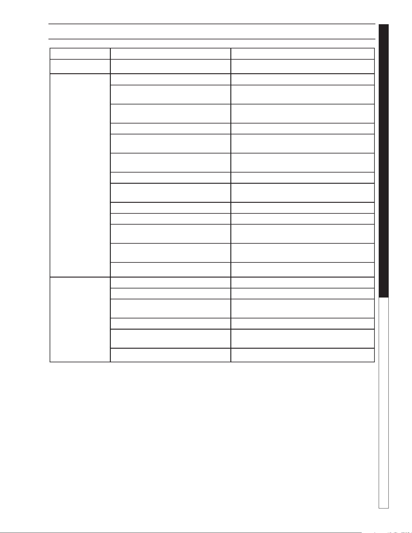
9.801-637.0 - C • Kärcher Classic Operator's Manual
21
PRESSURE WASHER Troubleshooting Guide
TROUBLESHOOTING
PROBLEM POSSIBLE CAUSE SOLUTION
OIL DRIPPING
Oil seal worn Check and replace if necessary.
LOW
OPERATING
PRESSURE
Faulty pressure gauge Install new gauge.
Insufficient water supply Use larger garden hose. Clean filter washer at
water inlet.
Old, worn or incorrect spray nozzle Match nozzle number to machine and /or
replace new nozzle.
Belt slippage Tighten or replace. Use correct belt.
Plumbing or hose leak Check plumbing system for leaks. Retape leaks
with teflon tape.
Faulty or misadjusted unloader valve
(where applicable)
Adjust unloader for proper pressure. Install
repair kit when needed.
Worn packing in pump Install new packing kit.
Fouled or dirty inlet or discharge valves
in pump
Clean inlet and discharge valve.
Worn inlet or discharge valves Replace with valve kit.
Obstruction in spray nozzle Remove obstruction.
Leaking pressure control valve
(where applicable)
Rebuild or replace as needed.
Detergent metering valve left open
sucking air or faulty metering valve
Close and /or replace metering valve.
Slow motor RPM Check incoming voltage.
LOW
WATER
TEMPERATURE
Improper size of gas lines See sizing gas lines.
Low gas pressure Increase gas pressure to machine.
Improper pressure regulator Specify BTU, building gas pressure 11 w.c.i.
to machine for correct sizing of regulator.
Low gas pressure Increase gas pressure
Soot buildup on coils not allowing heat
transfer
Clean coils.
Improper burner nozzle See serial plate.
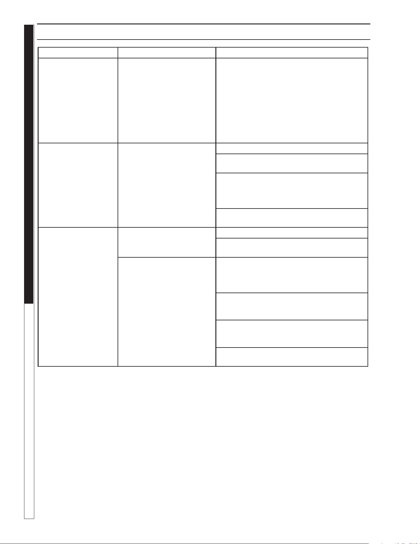
9.801-637.0 - C • Kärcher Classic Operator's Manual
PRESSURE WASHER Troubleshooting Guide
22
TROUBLESHOOTING
PROBLEM POSSIBLE CAUSE SOLUTION
FLOW & BURNER
SWITCH ON;
NO SPARK,
NO PILOT GAS
A. No main power
B. Faulty transformer
C. Faulty burner & flow switch
D. Faulty ignition control unit
With power switch on, open trigger on spray gun
and set your test meter to the 24 volt scale. Probe
terminals 24V and 24V(GND). If you do not read
24 volts, the problem is not the ignition system.
Perform normal system checks of main power,
transformer, thermostat and the limit control. If you
do read 24 volts at TH and GND, the problem is in
the ignition system. Check for loose or defective
wiring. If wiring is good, replace the ignition control
unit.
HAVE SPARK,
NO PILOT
GAS FLOW
Main gas supply turned off Set test meter to 24 volt scale.
1. Be sure main gas valve (gas cock or selector
arm) is turned on.
2. With gas on and system sparking, probe
terminals PV and 24V(GND). If pilot gas does
not flow with 24 volts at these terminals, replace
gas valve.
3. Probe terminals PV and MV/PV. If 24 volts not
present, replace ignition control box.
HAVE PILOT GAS,
NO SPARK
A. Defective ignitor/
sensor and or its wiring
Set test meter to ohm scale.
1. Disconnect the wire from the IGN terminal on
the ignition control unit.
B. Faulty ignition control unit 2. Touch one meter probe to the tip of the ignitor/
sensor rod in the pilot. Touch the other probe
to the quick connect at the other end of ignitor/
sensor wire.
3. If you have continuity from the tip of the ignitor/
sensor rod to the connector and no spark, replace
the ignition control unit.
4. If you do not have continuity through wire
and the ignitor/sensor, check for a loose wire
connection in the wire. Repair as needed.
5. Check to see if spark shorts to burner ring
through a cut in the ignitor wire.
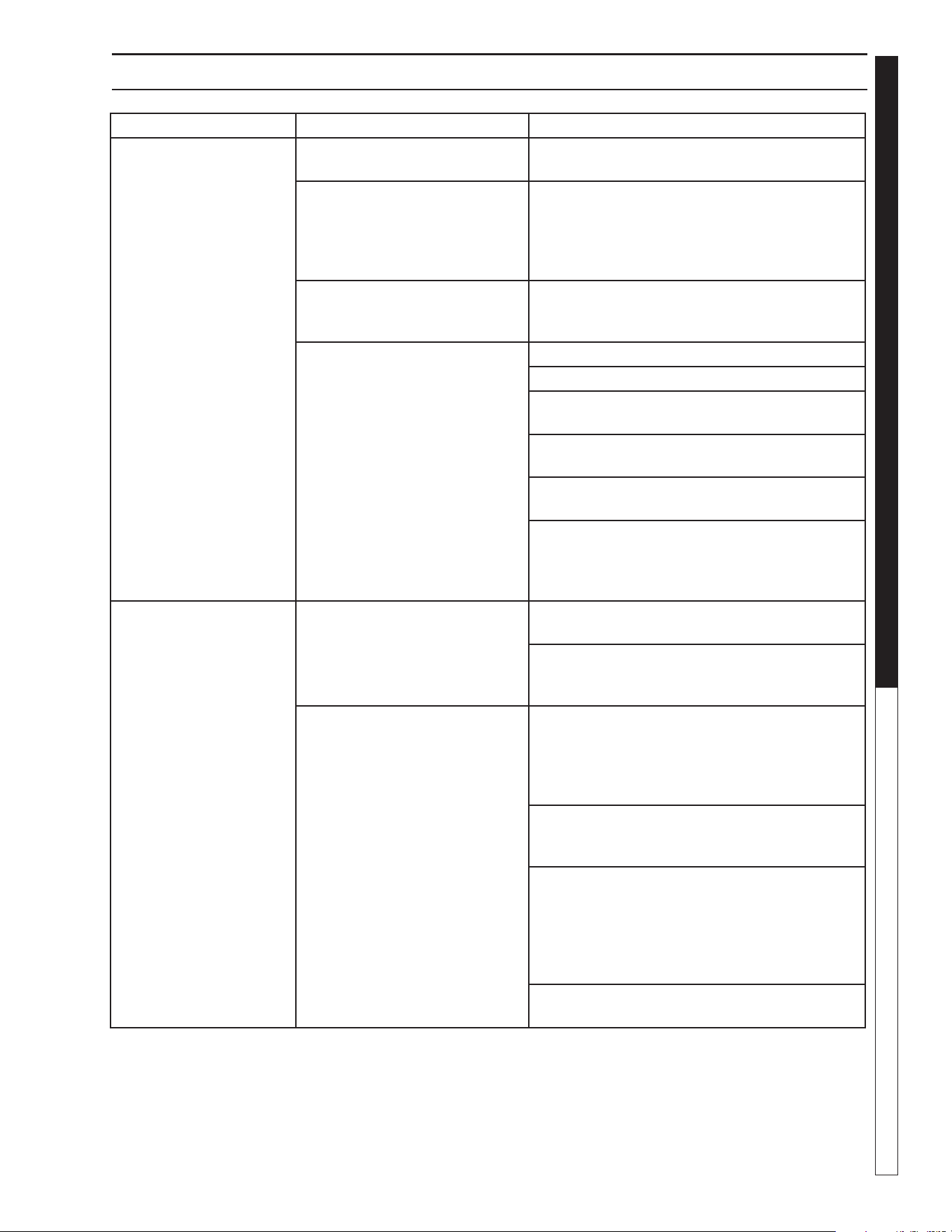
9.801-637.0 - C • Kärcher Classic Operator's Manual
23
PRESSURE WASHER Troubleshooting Guide
TROUBLESHOOTING
PROBLEM POSSIBLE CAUSE SOLUTION
HAVE PILOT FLAME,
MAIN BURNER WILL
NOT TURN ON
Faulty main valve coil in the
gas valve
Set test meter to 24 volt scale.
Faulty ignitor/sensor and/or its
wiring
With pilot flame on ignitor/sensor, probe terminals
MV and MV/PV on the ignition control unit. If you
read 24 volts here, but not at the gas valve,
there is a loose wiring connection. Repair or
replace as needed.
Ground wire not attached to
machine chassis
If you do read 24 volts at MV and MV/PV and
the pilot flame is impinging on the ignitor/sensor
rod, the problems may be:
Faulty ignition control unit a. Faulty ignitor/sensor and/or its wiring.
b. Faulty ignition control unit.
Set test meter to the ohm scale. Turn burner
switch off.
Check continuity through the green ground
wire and its connections.
Reconnect the ignitor/sensor wire and the
ground wire.
Turn burner switch on. With the pilot burning and
the flame on the ignitor/sensor rod, the main
burner should turn on. If it does not, replace the
ignition control unit.
SHORT-CYCLING
OF MAIN BURNER.
MAIN BURNER
TURNS OFF BEFORE
THE BURNER SWITCH
OR FLOW SWITCH
IS TURNED OFF
Draft condition pulls flame from
ignitor/sensor rod.
Check the thermostat by bypassing at
terminals P1 & 1.
Set thermostat high. With main burner on,
observe the pilot flame impingement on the
ignitor/sensor.
Faulty thermostat or water
temperature is too high
If pilot flame is small and draft condition pulls
flame from ignitor sensor rod, the burner will turn
off and then on again. a. Adjust pilot flame higher
or clean pilot oriface. b. Bend ignitor/sensor rod
closer to pilot flame.
If flame impingement on the ignitor/sensor is
stable and the system short-cycles, check the
limit switch.
Set test meter to 110 volt scale;
a. When the system cycles off, probe
the switch terminals of the limit switch.
b. If you read 24V accross the switch
terminals the limit switch is open.
Replace the limit switch.
A pilot flame set too high will also cause burner
to short cycle. Pilot flame lifts over ignitor/sensor.

9.801-637.0 - C • Kärcher Classic Operator's Manual
MANUAL
PRESSURE WASHER
24
MAINTENANCE AND SERVICE
Spray Nozzles:
Each machine is equipped with one or more spray
nozzles, depending on the model. Different spray
nozzles are calibrated for each machine, depending on
the flow and pressure of that particular model. Spray
nozzles vary in bore size and angle of spray. Popular
spray angles are 0°, 15°, 25°, 40°. When ordering,
please specify size and angle of nozzle. Nozzle size
for each machine is located on the serial plate.
Unloader Valves:
Unloader valves relieve pressure in the line when a
spray gun is closed. Unloader valves are preset and
tested at the factory before shipping. Occasional ad-
justment of the unloader may be necessary to maintain
correct pressure. For valve adjustment contact your
nearest dealer or call technical support. Tampering
with the factory setting may cause personal injury and/
or property damage, and will void the manufacturer's
warranty.
Winterizing Procedure:
Damage due to freezing is not covered by warranty.
Adhere to the following cold weather procedures when-
ever the washer must be stored or operated outdoors
under freezing conditions.
It is necessary to protect your machine against freez-
ing when temperatures drop below 32° F. Siphoning a
small amount of antifreeze into the system is recom-
mended. This is done by pouring a 50-50 mix of anti-
freeze and water into the float tank and then siphoning
100% antifreeze through the detergent line with the
pump on. If compressed air is available, an air fitting
can be screwed into the float tank strainer fitting, and
by injecting compressed air, all water will be blown out
of the system. The use of a draft diverter will prevent
the wind chill factor from freezing the coil.
Low Pressure Diagnosis:
(Machines with spray gun)
Refer to Troubleshooting Chart for low pressure. If the
trouble is found to be either the unloader or the pump,
your next step is to determine which is the problem.
This can be done by eliminating the unloader from the
system and attaching the 50' discharge hose directly
to the pump. If high pressure is developed in this man-
ner, the pump is good and the unloader needs to be
repaired or replaced. If low pressure is still present,
then the pump needs repairing.
CAUTION: When using this procedure to test
components keep the spray gun open at all times.
High Limit Hot Water Thermostat:
For safety, each machine is equipped with a high limit
control switch. In the event the temperature of the water
should exceed its operating temperature, the high limit
control will turn the burner off until the water cools.
Pumps:
Use only SAE 20/40 weight non-detergent oil. Change
oil after first 50 hours of use. Thereafter, change oil
every three months or at 500 hour intervals. Oil level
should be checked through use of the dipstick found
on the top of the pump or by the red dot visible through
the oil gauge window. Oil should be maintained at
that level.
HEATING COILS
To Check Water Heater Coil for Leaks:
With the main burners “OFF” start the pumping unit
and allow it to run for a few minutes. Check into the
burner compartment with a drop light or flashlight. If
no leaks are visible, then water dripping from coils is
condensation from the flue gases when the burners
are on.
Condensation from Heating Coil:
When cold water is being pumped into the water heater
coils, and the burners are on, condensation will form on
the coils and drip down into the burner compartment,
giving the appearance of a leaking coil, particularly
on cold humid days.
Deliming Coils:
In alkaline water areas, lime deposits can accumulate
rapidly inside the coil pipes. This growth is increased
by the extreme heat build up in the coil. The best
prevention for liming conditions is to use high quality
cleaning detergents. In areas where alkaline water is
an extreme problem, periodic use of Mongoose Coil
Conditioner (part # 8.914-296.0) will remove lime and
other deposits before coil becomes plugged. (See the
following instructions for use of Coil Conditioner.)
Periodic flushing of coils is recommended.
1. Fill a container with 2 gallons of water, then add
1 lb. of deliming powder. Mix thoroughly.
2. Remove nozzle from spray gun assembly and put
spray gun into container. Secure the trigger on the
spray gun into the open position.
3. Attach a short section (3-5 ft.) of garden hose to
machine to siphon solution from an elevated con-
tainer, or add mixture to the float tank. Turn pump
switch on allowing solution to be pumped through
coils and back into the container. Solution should
be allowed to circulate 2-4 hours.
4. After circulating solution, flush entire system with
fresh water. Reinstall wand assembly to spray gun.
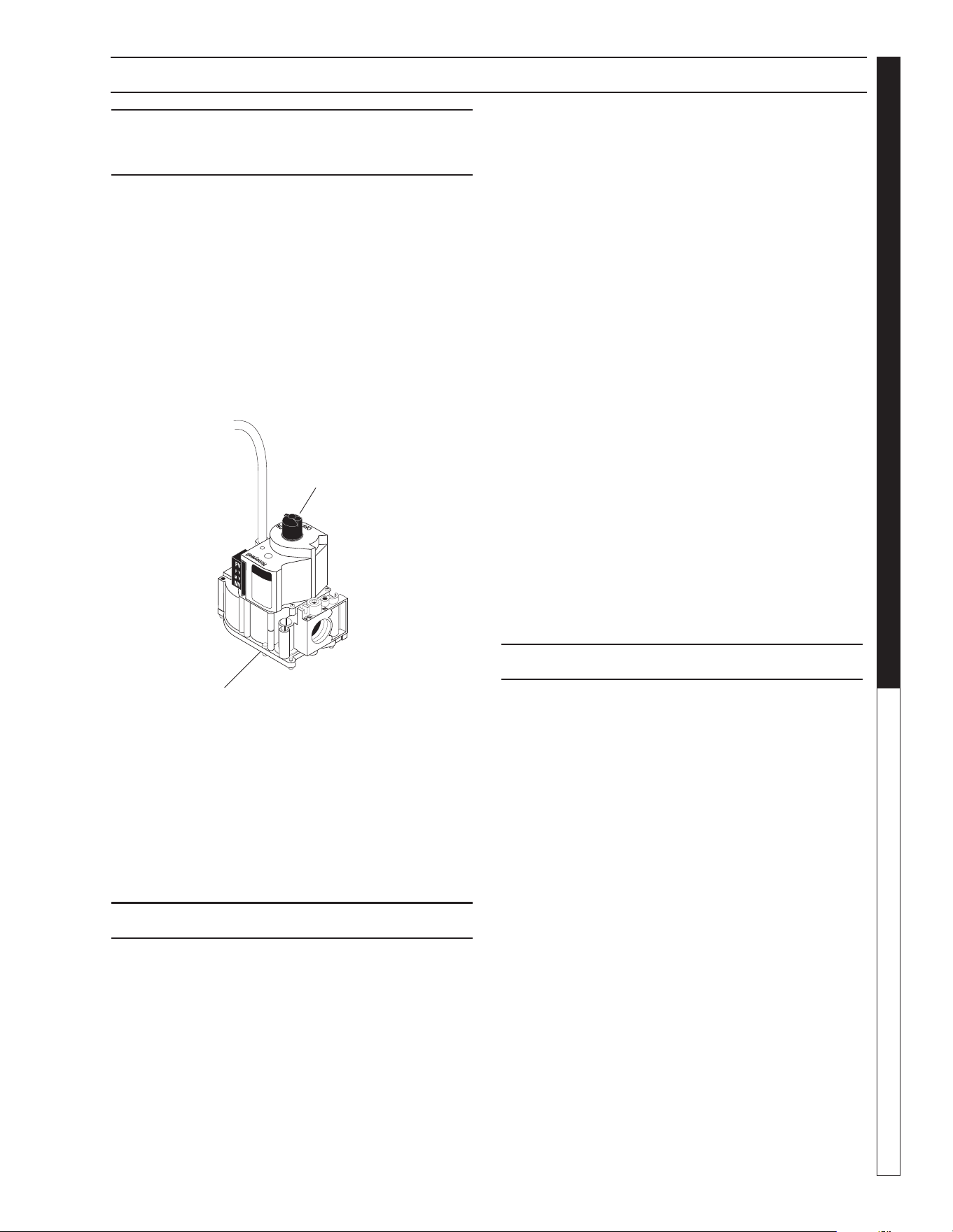
9.801-637.0 - C • Kärcher Classic Operator's Manual
25
PRESSURE WASHER
MANUAL
MAINTENANCE & SERVICE
Gas Valve Regulator Adjustment
GAS VALVE REGULATOR
ADJUSTMENT
Adjustment of the built-in regulator isn’t normally nec-
essary, since it is preset at the factory. However, field
adjustment may be accomplished as follows:
1. Attach manometer at pressure tap port.
2. Remove regulator adjustment screw cap.
3. With a small screwdriver, rotate the adjustment
screw clockwise to increase or counterclockwise
to decrease gas pressure.
4. Replace regulator adjustment screw cap (see
Figure 5).
Figure 5
Rupture Disk
If pressure from pump or thermal expansion should
exceed safe limits, the rupture disk will burst allow-
ing high pressure to be discharged through hose to
ground. When disk ruptures it will need to be replaced.
The Rupture Disk should be replaced every two years.
PROPANE GAS
General Safety Precautions
Have a qualified gas service person assist in any gas
burner installation or service. Few maintenance people
or mechanics are knowledgeable in gas controls or
related safety practices. Propane gas is heavier than
air; unburned propane gas will gravitate to the floor
rather than rise out of the stack. Hence, adequate floor
space and good ventilation are especially important
with propane systems.
Gas Pressure Requirements
All propane fired machines operate on vapor propane
fuel only. They are designed to operate at a pressure of
11 w.c.i. (between 1/3 and 1/2 of one psi), and are
often operated at even higher pressures when extra
heat is needed.
Exterior regulators are needed to control gas pressure.
Propane bottles are not included with the machine. A
pressure regulator should be installed between pro-
pane bottle and gas valve.
Propane Cylinder Capacity
An important consideration with propane systems is
the capacity of the supply cylinder relative to the needs
of the burner. The burner operates on propane as a
vapor gas. As gas is used from the propane cylinder,
the liquid in the cylinder boils to maintain vapor gas
pressure. This boiling process cools the liquid, and in
a heavy, continuous-demand situation, the liquid tem-
perature can fall to the point at which it cannot provide
vapor gas as rapidly as is needed. In this case, it may
be necessary to warm the propane cylinder by direct-
ing a warm spray, not over 120°F, on the cold cylinder
or by manifolding two propane bottles together to in-
crease total vaporization capacity. It is recommended
that a minimum 100 lb. vapor propane bottle be used
on the machine, depending on the length of running
time desired.
BURNER FEATURES
Operated Automatic Valve
This machine is equipped with an Intermittent Pilot
Ignition System. This system is designed to eliminate
the need for a constant burning pilot. Lighting of the
pilot is accomplished through electronic spark ignition
each time the burner switch is turned on. Do not at-
tempt to light the appliance manually as a burn injury
or electrical shock may result. The pilot light will remain
on and the main gas valve is turned off when the spray
gun is closed.
Care of Main Burner
Due to condensation from heater coils dripping down
on the burners, scale build-up may occur in the burner
jet orifices.
1. TO REMOVE BURNER MANIFOLD FROM
WATER HEATER COIL:
Turn off the gas to the main burner by turning the
knob to the “OFF” position on the gas valve and
the main gas supply.
Disconnect the pilot and ignition lines from the gas
valve. Disconnect union in main burner line below
thermostat. Slide burner manifold out through shell
opening.
On/Off
Switch
Inlet View
Outlet
Manifold Pressure
Adjustment Screw
Under Cap
Gas Valve
Regulator
Adjustment
Lines To
Pilot Light
98016360-26

9.801-637.0 - C • Kärcher Classic Operator's Manual
MANUAL
PRESSURE WASHER
26
MAINTENANCE & SERVICE
2. TO CLEAN BURNER JETS:
Select proper size drill for type gas involved. Use
pin vise to hold drill and ream out each jet orifice.
CAUTION: Do not ream out orifices to a
larger size.
If the water heater will be exposed to freezing weather,
an anti-freeze solution should be circulated through the
coil by whatever means are available for the particular
system the water heater is used on.
To Adjust Pressure Regulator
Adjustment of the pressure regulator is not normally
necessary since it is preset at the factory. However,
field adjustment may be accomplished as follows:
1. Manometer attachment may be accomplished at
the pressure tap plug.
2. Remove regulator adjustment screw cap (see
Figure 5, page 23).
3. With small screwdriver, rotate adjustment screw
clockwise to increase, or counterclockwise to
decrease pressure.
4. Replace regulator adjustment screw cap.
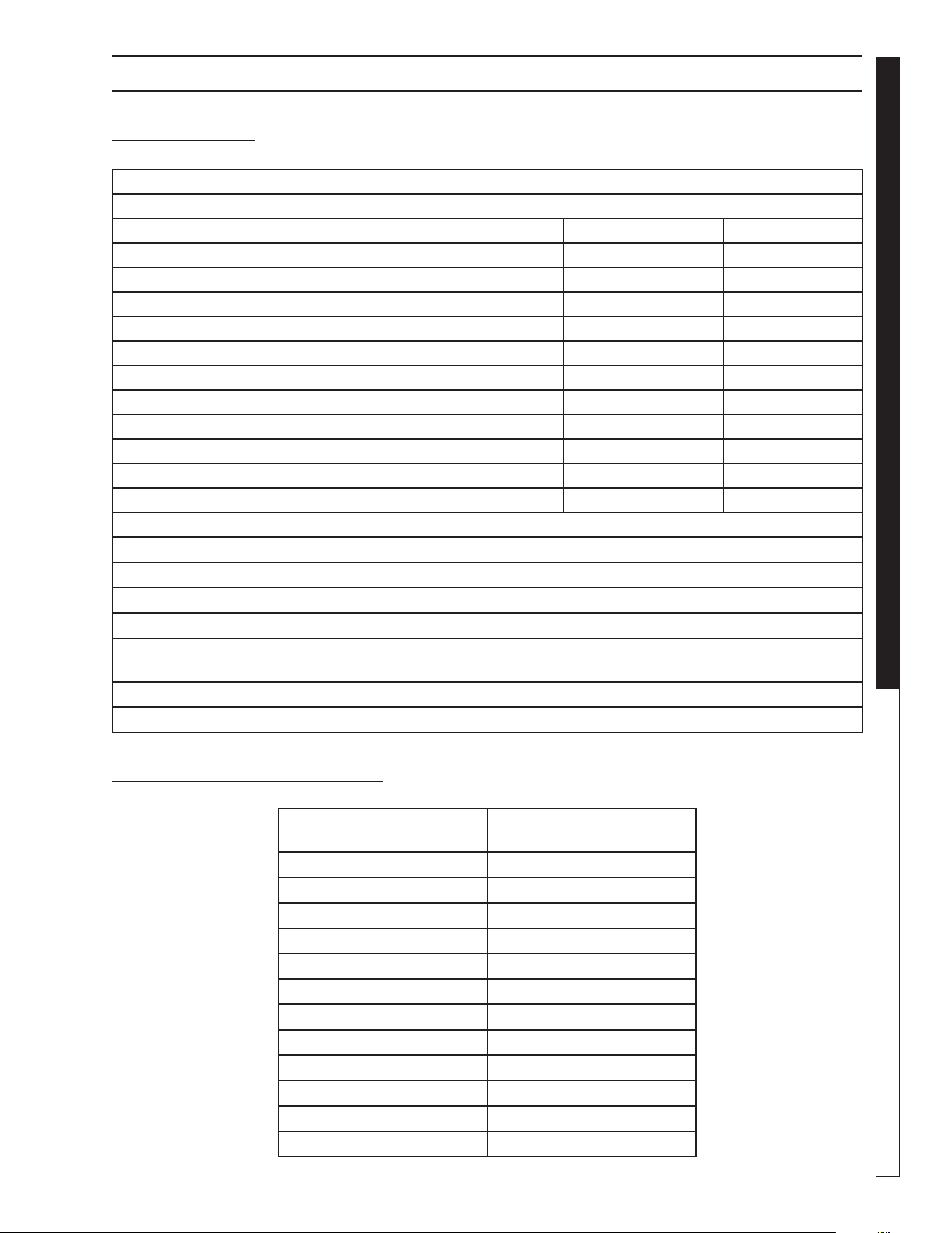
9.801-637.0 - C • Kärcher Classic Operator's Manual
27
PRESSURE WASHER
MANUAL
MAINTENANCE AND SERVICE
BASIC FACTS
Based on 60° Propane Butane
1 Cu. Ft. NG Approx 1000 BTU
Formula
C3H8 C4H10
Vaporization Point (°F) -43.7 31.1
Specific Gravity (Vapor) 1.522 2.006
Specific Gravity (Liquid) 0.508 0.584
Lbs. per Gal. (Liquid) 4.23 4.87
BTU per Cu. Ft. (Vapor) 2.563 3.39
BTU per Gal. (Liquid) 91.547 102.032
BTU per Lb. (Liquid) 21.591 21.221
Cu. Ft. per Lb. (Liquid) 8.607 6.53
Cu. Ft. per Gal. (Liquid) 36.45 31.8
Octane Number 125 91
Molecular Weight 44.09 58.12
To Calculate Running Cost: 1,000 BTU = 1 Cu. Ft.
100 Cu. Ft. = 1 Therm
1 Therm = 1 Hour
Cost of Gas per Therm = Cost to Run
Example Using Natural Gas at 50¢
Therm:
400,000 BTU Machine
400 Cu. Ft. (400,000 / 1,000)
4 x 50¢ = $2.00 / Hour to Run ((400 / 100) x cost of gas)
OIL CHANGE RECORD
Date Oil Changed Month/
Day/Year
Estimated Operating Hours
Since Last Oil Change
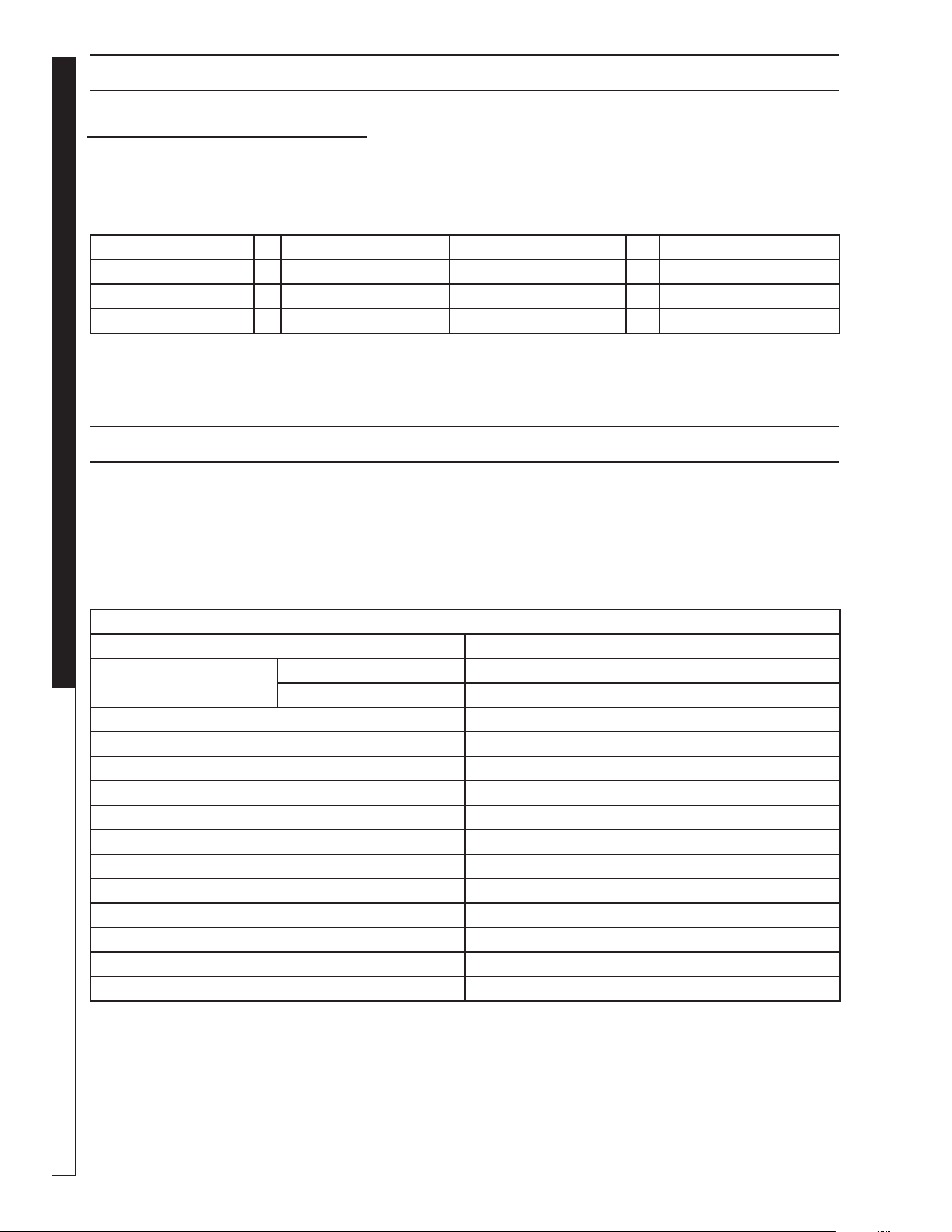
9.801-637.0 - C • Kärcher Classic Operator's Manual
MANUAL
PRESSURE WASHER
28
PRESSURE EQUIVALENTS
Simply stated, pressure is the force exerted by a gas or liquid attempting to escape from a container. It is useful
to know how strong this “attempt to escape” is. Pressure can be measured with a manometer or with a pressure
gauge. At the lower levels, it is expressed in water column inches i.e. 11 w.c.i. Higher pressures are expressed
in terms of the force exerted against a square inch of area, for example, 125 lbs. per square inch (125 psi).
MAINTENANCE AND SERVICE
1" Water Column = 50 oz./sq. in. 11" Water Column = 6.35 oz./sq. in.
11" Water Column = 4 lb./sq. in. 1 lb./sq. in. = 27.71" Water Column
1 lb./sq. in. = 14.73 lbs./sq.in 1" Mercury = .39 lb./sq. in
1 Std. Atmosphere = 14.73 lbs./sq. in.
PREVENTATIVE MAINTENANCE
This pressure washer was produced with the best available materials and quality craftsmanship. However,
you as the owner have certain responsibilities for the correct care of the equipment. Attention to regular
preventative maintenance procedures will assist in preserving the performance of your equipment.
Contact your dealer for maintenance. Regular preventative maintenance will add many hours to the life of your
pressure washer. Perform maintenance more often under severe conditions.
MAINTENANCE SCHEDULE
Replace Fuel Lines Annually
Pump Oil
Inspect Daily inspect the oil level
Change After first 50 hours, then every 500 hours or annually
Clean Burner Filter Annually
Remove Burner Soot From Heating Coil Annually
Check Belt Tension Monthly
Descale Coil Annually - (more often if required)
Replace High Pressure Nozzle Every 6 months
Replace Quick Connects Annually
Clean Water and Chemical Screen/Filter Weekly
Clean Float/Supply Tank Every 6 months
Replace HP Hose If there is any sign of wear
Grease Motor Every 10,000 hours
Check Burner Pilot Jets Annually
Rupture Disk Replace every 2 years


HDS • 9.801-637.0 • Printed in U.S.A.