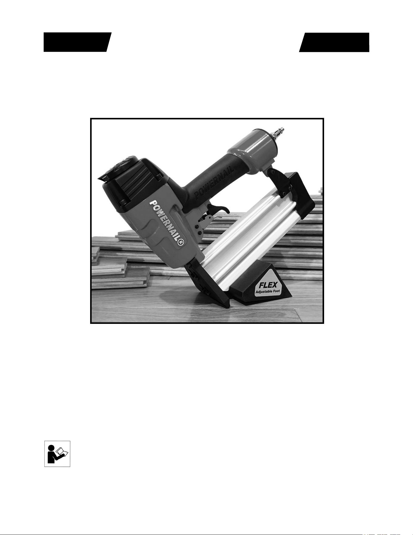
Model 50F Pneumatic Powernailer™
POWERNAIL
®
CO.
REV 2024.08.14
WARNING
OPERATION AND MAINTENANCE MANUAL
MANUAL DE OPERACION Y DE MANTENIMIENTO
MANUEL D’INSTRUCTIONS ET D’ENTRETIEN
Read this manual before you use this Powernailer®. Follow all safety warnings and
instructions. If you are uncertain about the operation of the nailer, call us directly
at 1-800-323-1653 for assistance or contact the closest Powernail Dealer for help.
Please retain this information for future reference.

2
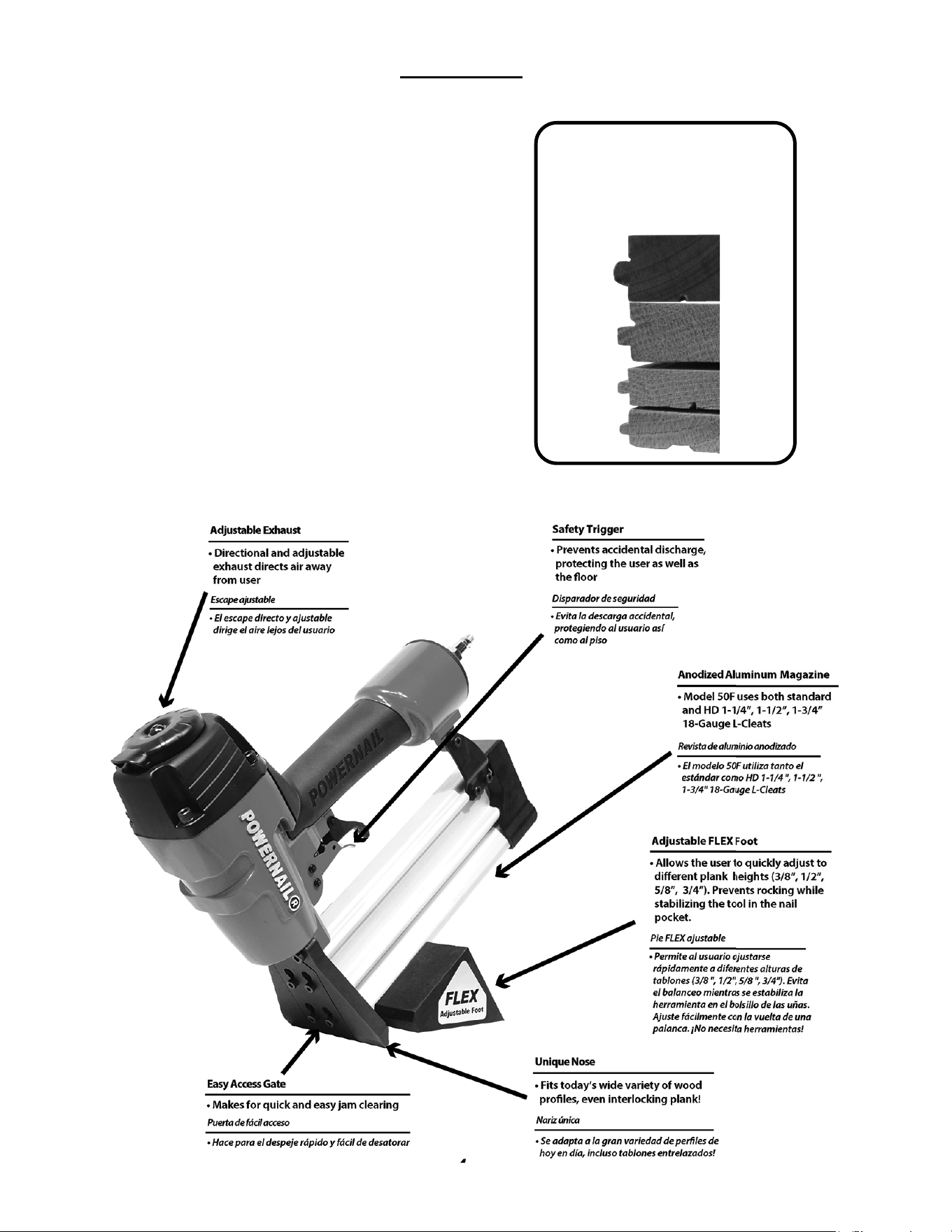
The Model 50F trigger-pull nailer is designed to bring Powernail quality and fl ooring expertise
to a pneumatic nailer. The Model 50F is designed for use with 1-1/4” to 1-3/4”, 18 gauge
L-Cleat Powernails
®
. The Model 50F nails from 3/8” to 3/4” fl ooring through the use of a
FLEX adjustable foot assembly that can be adjusted to fi t diff erent fl ooring profi les.
INTRODUCTION
INDEX
LIMITED WARRANTY
POWERNAIL® Company, Inc. warrants to its customer, and to the fi rst end-
use purchaser of POWERNAIL Model 50F POWERNAILER purchased from
an authorized POWERNAIL distributor, that each serialized manufactured
Model 50F POWERNAILER by POWERNAIL®, for a period of 12 months
from the date of purchase; shall be free of defects in materials and workmanship
and will meet POWERNAIL’S specifi cations in eff ect at the time of product
shipment. POWERNAIL will repair or replace, at its option, any Model 50F
POWERNAILER that does not conform to this warranty. Claims must be made
no later than fi fteen (15) days after the end of the warranty period. POWERNAIL
will perform all repair or replacements itself or through its authorized distributors.
POWERNAIL is not responsible for shipping, labor or other direct or indirect
costs. Damage caused by abuse, misuse, unusual or excessive wear is excluded.
Repair or modifi cation of the Products by unauthorized parties will void this
warranty. The customer is responsible for returning Products to POWERNAIL
for verifi cation of nonconformance. Warranties for Products not manufactured
by POWERNAIL are limited to warranties provided to POWERNAIL by the
manufacturer of such product that are assignable to customer.
THESE WARRANTIES AND REMEDIES ARE EXCLUSIVE OF ALL OTHERS,
EXPRESS OR IMPLIED. THE WARRANTIES OF MERCHANTABILITY
AND FITNESS FOR PURPOSE ARE EXPRESSLY EXCLUDED. IN NO
EVENT SHALL POWERNAIL’S LIABILITY FOR A WARRANTY CLAIM
EXCEED THE PRICE PAID TO POWERNAIL FOR THE NONCONFORMING
PRODUCT, REGARDLESS OF THE FORM OR BASIS OF THE CLAIM OR
CAUSE OF ACTION.
Index............................ 2
Warranty........................ 2
Operating the tool.......... 4-6
FLEX Foot Adjustment...5
Air Supply...................... 6
Maintenance.................. 7
Safety Labels................. 7
Loading Fasteners.........6
Clearing a jam............... 8
Troubleshooting Chart... 9
Schematic / Parts List.. 10-11
Nail Depth Chart............ 12
Phone Support............. 12
Web Site........................ 12
Powernail Company Info 12
Always DISCONNECT THE AIR SUPPLY before making any adjustments, repairing, clearing jams or
when the Nailer is not in use. Do not use on scaff olding or ladders and disconnect nailer from air supply
when transporting between installation areas.
Never attach the female end of a quick disconnect to the Nailer. This will trap air inside the Nailer and
permit it to be discharged. Only the unrestricted male connection should be attached to the Nailer.
Nailer requires an air source that can continuously deliver 70 to 120 psi at 3-1/2 cubic feet of air per
minute for operation. Normal air pressure should not exceed 120 psi or damage to the Nailer and seals
may occur. Excess air pressure can cause the Nailer to explode. Do not continue to use a tool that leaks
air or does not function properly. Notify your nearest Powernail representative if your tool continues to
experience functional problems.
To prevent fi re or explosion, use only regulated compressed air—do not use bottled gases of any
kind (no oxygen or combustible gasses) to power this Nailer. Nailer is intended for use installing wood
fl ooring and is not to be used for purposes not specifi ed in the operations manual.
Do not use any nails other than Powernail® Powercleats which are 18 gauge L-cleat nails specifi cally
designed for use in any 18 gauge Powernailer. Powercleat nails are available in lengths of 1-1/4”, 1-1/2”
and 1-3/4”. Contact your Powernail Dealer for the correct Powercleats for the Model 50F.
Use only Powernail replacement parts in the repair or maintenance of this nailer. Parts or repair services
are available from the manufacturer or from agents authorized by the manufacturer. Repairs should be
carried out only by trained service personel in the fi eld of fastener driving tools who will observe proper
safety controls while performing maintenance. Service personel should be qualifi ed to assess the safe
working condition of fastener driving tools.
Always make sure Nailer is empty of nails before connecting air hose, so as to prevent any accidental
discharge from occurring. ONLY CONNECT AIR TO AN UNLOADED NAILER.
Do not depress the trigger when loading. If the fasteners are jammed, disconnect the tool from the air
supply before you remove the jammed nails.
Never place any part of the body in the discharge path of the Nailer when air is connected to
the Nailer. Never point the tool at yourself or others, even if the tool is not loaded. For safety,
keep out of reach of children. Never leave the Nailer unattended while it is connected to an
air supply. Never disable, clamp or tape the safety trigger in an activated position.
Do not fi re into hard materials or attempt to use on hard or brittle material such as concrete, steel or tile.
Before using this tool, carefully check that all parts are working correctly. Do not use the tool if it is not
operating correctly, check for causes and adjust as necessary for proper operation. When not in use, the
tool should be cleaned, fully assembled and then stored in a dry location. This will extend the life of the
tool and reduce any oxidation.
When operating this Nailer, the operator and others in the work area should ALWAYS
wear approved SAFETY GLASSES, with front and side eye protection. Eye protection
will help guard against fl ying nails and debris, which could cause severe eye injury.
EAR PROTECTION should be used to prevent hearing damage when there are high
noise levels in the work area. ALWAYS use ear plugs with a noise reduction rated at 29
db or higher at a construction site.
Do not operate this tool if it does not contain a legible WARNING LABEL.
SAFETY INSTRUCTIONS
3
Noise characteristic values in accordance with ENxx1:
A-weighted single-event sound pressure level at operator’s position: LPA, ls94dBA
A-weighted single sound pressure level:LpA,ls,lm89dBA
Vibration characteristic values in accordance with ISO 8662, PART II
Weighted root mean square acceleration 3.2m/s²
4
The Model 50F nails down fl ooring from
3/8” to 3/4” using the Powernail FLEX adjustable
foot assembly that can be adjusted to fi t diff erent
fl ooring profi les.
To use the Model 50F, properly position the tool
on the fl ooring plank (See picture below). Pull up
and hold the black safety trigger to activate the
orange fi ring trigger. The nailer will drive and set
the nail at the correct angle.
Note: Modifying or altering the nailer in anyway
can potentially cause injury and may void the
warranty.
The unique body design allows for diff erent grip
angles and has an adjustable exhaust port to
redirect nailer exhaust.
OPERATION
The Model 50F installs
tongue and groove
fl ooring from
3/8” to 3/4”
.
4
3/4”
19 mm
5/8”
15 mm
1/2”
12 mm
3/8”
9 mm
5
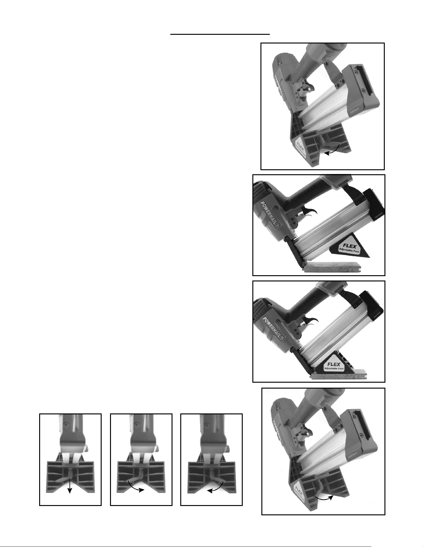
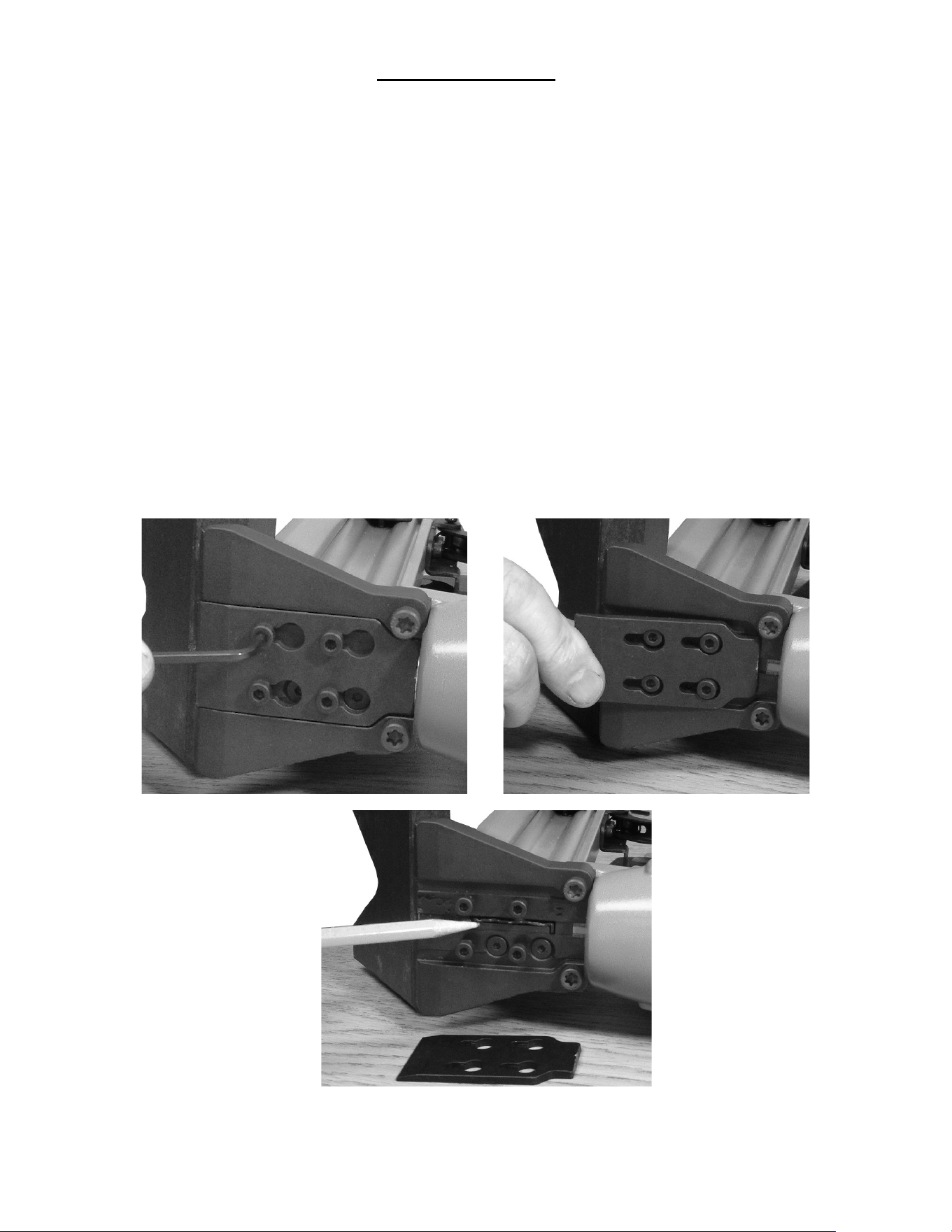
Use the photos on the right for reference:
1.) First loosen the tool’s FLEX foot by turning the lever
from right to left/counter clockwise. (See image 1.a)
a.) The FLEX foot should now freely slide up-and-down
the magazine.
2.) Using a sample of your fl ooring, slide the FLEX foot
back on the channel and set the nose of the stapler
securely into the nail pocket (see image 1.b). Important:
Orient the board as it is intended to be installed, with the
fl oor board’s surface facing up.
3.) While keeping the nose of the stapler/nailer in the
nail pocket (resting on top of the tongue and against the
shoulder) slide the FLEX foot forward until it lies fl at on
the fl ooring surface. (see image 1.c)
4.) Now turn the FLEX foot’s adjustment lever from left
to right (clockwise) to tighten the foot. (see image 1.d)
5.) Always test fi re into a test piece of fl ooring to ensure
the nail is setting correctly.
If your FLEX foot is not tight enough:
1.) If your tool’s foot is not tight enough or if the FLEX
foot is not maintaining its “set” position, you may adjust
its tightness by pulling OUT on the lever (see image 1.e)
and turning it from right to left (see image 1.f) . Release
the lever (make sure that it reseats) and turn from left
to right (see image 1.g). This is a form of ratcheting
mechanism and does not require any tools to loosen or
tighten.
a.) ***If your Flex Foot needs to be loosened, reverse
the process listed above.
2.) If you are experiencing trouble in making this
adjustment please visit www.powernail.com/f-series-
adjustment to view a helpful demonstration video.
FLEX Foot Adjustment
1.a)
1.b)
1.c)
1.d)
How to adjust your tool’s foot to your fl oor’s thickness:
1.e) 1.f) 1.g)
6
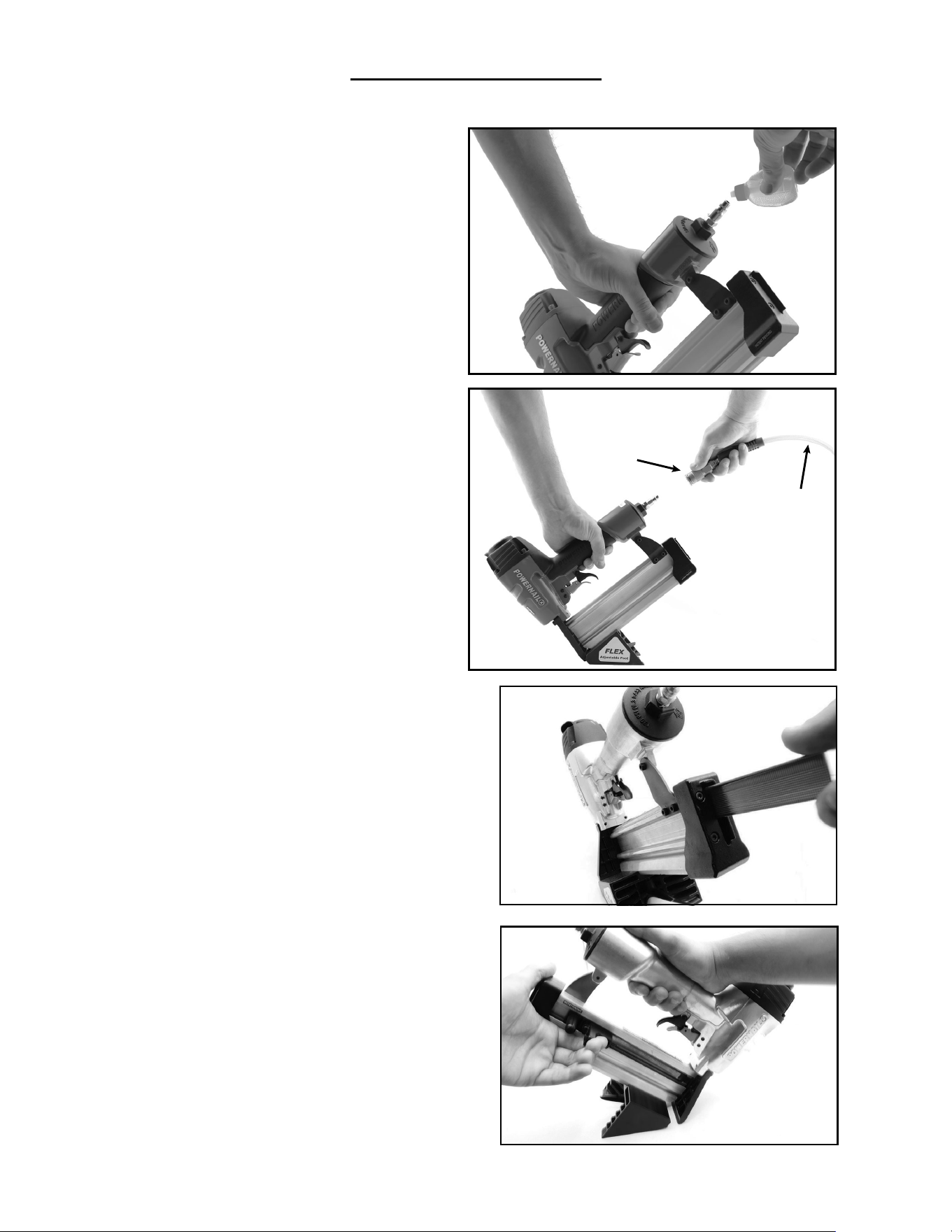
1.) Insert a full stick of 1-1/4”, 1-1/2”
or 1-3/4” 18 gauge Powercleats
through the slotted Magazine Rear
Cover(49) into the Magazine (47)
OPERATION, continued...
Figure 4.
Figure 5.
(Figure 4)
2.) Pull back the spring loaded Nail
Pusher (39) over the nails until it
contacts the last nail and slowly release
the Nail Pusher. The nailer is now
loaded. (Figure 5)
CONNECTING THE TOOL TO AN AIR
SUPPLY
Your air tool is fully assembled when you
receive it. Before using it, attach the air line
and desired air system accessories. Be
sure the air hose is depressurized when
installing or removing adapters to the air
line. To prevent misfi re, do not connect air
to a loaded nailer.
1.) An automatic airline oilier is
recommended but oil may be added
manually before every operation or after
about 8 hours of continuous use.
2.) Place two (2) drops of air-tool oil in the
air plug as shown (Figure 2). If you are
using an automatic in-line oiler, check and
add oil if necessary.
3.) Turn your compressor on and set
the compressors pressure regulator to
the proper pressure. Normal operating
pressure should be adjusted between
70-120 psi based on fastener and wood
being used.
4.) Connect the tool to the air supply
(Figure 3).
LOADING THE FASTENERS
Figure 3.
Quick
Connector
Air Hose
Figure 2.
REGULAR MAINTENANCE
1.) Frequent, but not excessive, lubrication is required for best performance. Oil added through the
airline connection will lubricate internal parts. An automatic airline oilier is recommended but oil may be
added manually before every operation or after about 8 hours of continuous use.
Only a few drops of oil at a time are necessary. Too much oil will collect inside the tool and be blown out
during the exhaust cycle. ONLY USE PNEUMATIC TOOL OIL. Do not use detergent oil or additives, as
these lubricants will cause accelerated wear to the seals in the tool.
2.) Use a small amount of oil on all moving surfaces and pivots.
7
3.) Dirt and water in the air supply are major causes of pneumatic tool wear. Use a fi lter/oiler for better
performance and longer life. The fi lter must have adequate fl ow capacity for the specifi c application.
4.) Keep tools clean for better and safer performance. Use nonfl ammable cleaning solutions only if
necessary. CAUTION: Soaking the tool may damage O-rings and other
tool parts.
MAINTENANCE
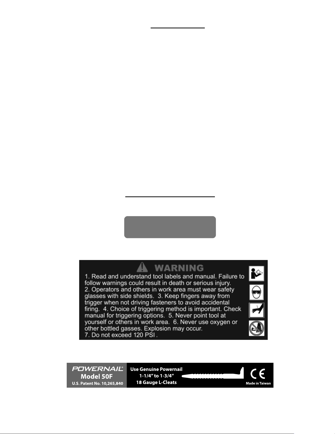
NAILER SAFETY LABELS
Operating Pressure
70 - 120 psi
8
CLEARING A JAM
Disassembly: (See Figure 7.)
1) NOTE: Do not remove the four M4 screws (80).
2) Loosen the 4 M4 screws (78) with a 3mm allen wrench.
3) Slide the gate plate down until it is free from the nose..
6) Lift the gate plate (72) off .
5) Inspect and clear any debris from the drive blade (27) and its path.
Reassembly:
1) Install the the gate plate over the four M4 screws (72).
2) Slide the gate plate upwards as far as it go.
3) Tighten the four M4 screws.
4) Unit is ready for funtional testing.

PROBLEM POSSIBLE CAUSE SOLUTION
1
Air leaking at
Trigger area
1. O-ring (34) in trigger valve is damaged.
2. Trigger valve head (34) is damaged.
3. Trigger valve stem, seal or O-ring (34) is
damaged.
1. Check and replace O-ring.
2. Check and replace trigger
valve head.
3. Check and replace trigger valve stem,
seal or O-ring.
2
Air leaking between
body and drive guider
Damaged bumper (21). Check and replace bumper.
3
Air leaking between
body and cylinder cap
1. Screw loose (5).
2. Damaged gasket (22).
1. Tighten screws.
2. Check and replace gasket.
4
Blade driving
fastener
too deeply
1. Worn bumper (21).
2. Air pressure is too high
1. Replace bumper.
2. Adjust the air pressure.
5
Runs slowly or
has loss of power
1. Insuffi cient oil.
2. Insuffi cient air supply.
3. Broken spring in cylinder cap (9).
4. Exhaust port (3) in cylinder cap is blocked
1. Lubricate as instructed
2. Check air supply.
3. Replace spring.
4. Replace damaged internal parts.
6
Tool skips a fastener
1. Worn bumper (21) or damaged spring (38).
2. Dirt in gate (49).
3. Inadequate airfl ow to tool.
4. Worn or dry O-ring (17) on piston.
5. Cylinder cap seal leaking (22).
1. Replace bumper or pusher spring.
2. Clean drive channel of front plate.
3. Check hose and compressor fi ttings.
4. Replace O-ring or lubricate.
5. Replace seal.
7
Fasteners are
jammed
(see page 8)
1. Joint guider is worn (25).
2. Fasteners are wrong size or damaged.
3. Magazine or front plate screws are loose (45).
4. Blade (15) in piston assembly is damaged.
1. Replace joint guider.
2. Use the recommended and
undamaged fasteners.
3. Tighten screws.
4. Replace piston assembly.
8
Tool will not drive
down tight
1. Worn blade in piston assembly.
2. Lack of power.
3. Slow cycling and loss of power.
1. Replace piston assembly.
2. Adjust to adequate air pressure.
3. Check cylinder cap spring for
broken coils or reduced length.
Check if exhaust port of cylinder
cap is restricted.
Here are some common issues that may occur during use.
If the nailer is not working as it should, stop using the tool immediately and resolve the
issue before continuing.
9
TROUBLE SHOOTING CHART

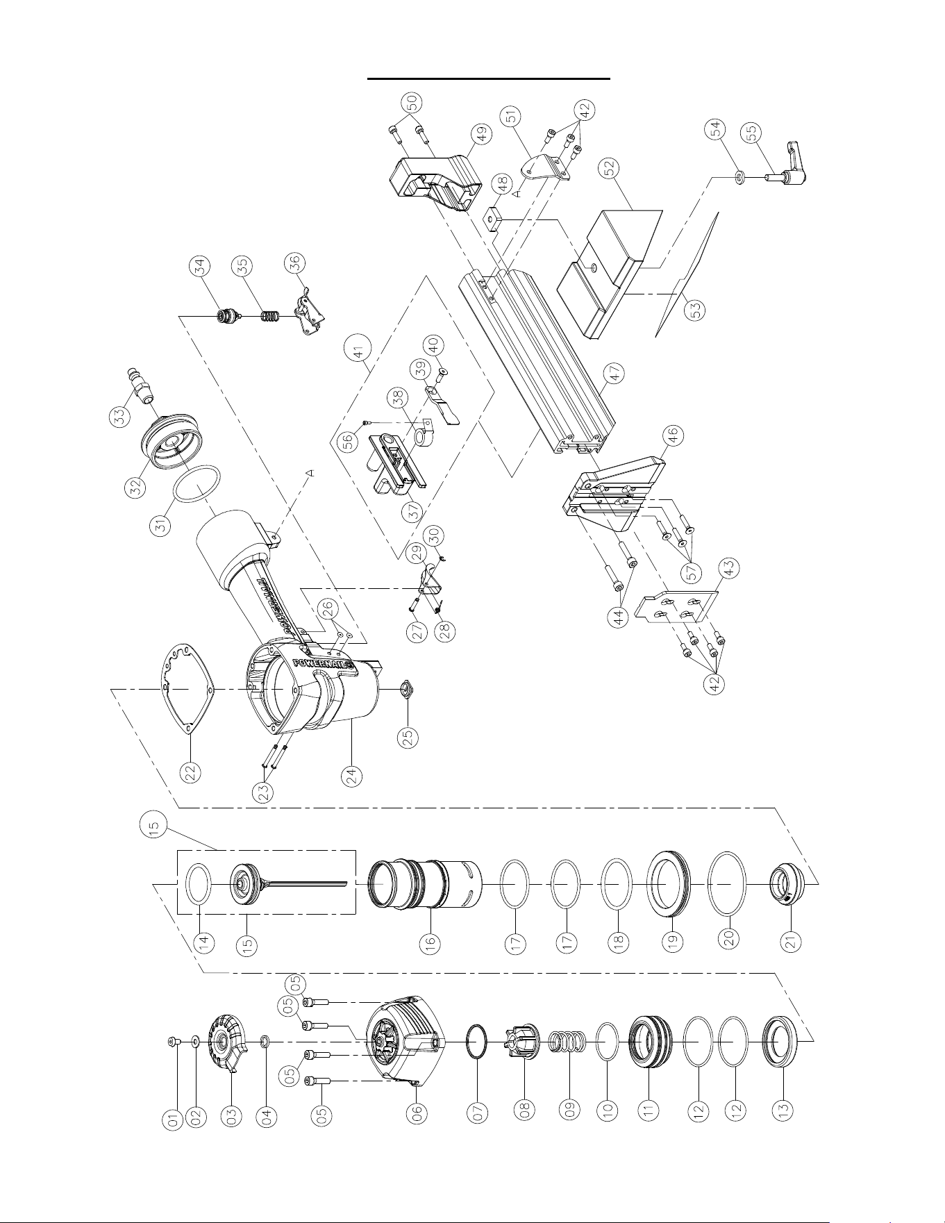
10
MODEL 50F PARTS LIST
KEY: S=Sold Separately, N/A= Not available separately, KIT=Sold as part of a Kit,
ITEM DESCRIPTION Avail. QTY PART #
1 UM.HD.BOLT S 1 09-50F001
2 FLAT WASHER S 1 09-50F002
3 EXHAUST COVER,
METAL
S 1 09-50F003
4 SEAL S 1 09-50F004
5 HEX.SOC.
HD.BOLT+SW
S 4 09-50F005
6 CAP S 1 09-50F006
7 SPACER S 1 09-50F007
8 PISTON STOPPER** S 1 09-50F008
9 SPRING** S 1 09-50F009
10 O RING** KIT 1 -
11 PISTON HEAD VALVE S 1 09-50F011
12 O RING** KIT 2 -
13 SEAL S 1 09-50F013
14 O RING** KIT 1 -
15 PISTON/DRIVE
BLADE
N/A 1 -
15A DRIVE BLADE
ASSEMBLY W/ (#14
O-RING)
S 1 09-50F015A
16 CYLINDER S 1 09-50F016
17 O RING** KIT 2 -
18 O RING** KIT 1 -
19 COLLAR S 1 09-50F019
20 O RING KIT 1 -
21 BUMPER S 1 09-50F021
22 CYLINDER CAP SEAL S 1 09-50F022
23 STEPPED PIN S 2 09-50F023
24 BODY N/A 1 -
25 JOINT GUIDE S 1 09-50F025
26 O RING** S 2 09-50F026
27 STEPPED PIN S 1 09-50F027
28 TOR. SPRING S 1 09-50F028
29 TRIGGER S 1 09-50F029
30 E RING S 1 09-50F030
31 O RING** S 1 09-50F031
ITEM DESCRIPTION Avail. QTY PART #
32 END CAP S 1 09-50F032
33 AIR PLUG S 1 09-50F033
34 TRIGGER VALVE
ASSEMBLY^
S 1 09-50F034
35 SPRING S 1 09-50F035
36 BUMP FIRE TRIGGER S 1 09-50F036
37 PUSHER GUIDE S 1 09-50F037
38 SPRING S 1 09-50F1038
39 PUSHER S 1 09-50F1039
40 FLAT HD SELF
SCREW
S 1 09-50F040
41A PUSHER ASSEMBLY S 1 09-50F1041A
42 HEX.SOC.HD.BOLT S 7 09-50F042
43 NOSE COVER / GATE
PLATE
S 1 09-50F043
44 HEX.SOC.HD.BOLT S 2 09-50F044
46 NOSE / GATE S 1 09-50F1046
47 MAGAZINE S 1 09-50F1047
48 FLEX FOOT LOCK
NUT
S 1 09-50F048
49 MAGAZINE REAR
COVER
S 1 09-50F049
50 HEX. SOC. HD. BOLT S 2 09-50F050
51 BRACKET S 1 09-50F051
52 FLEX FOOT BASE S 1 09-50F052
53 NO-MAR PAD S 1 09-50F053
54 FLAT WASHER S 1 09-50F054
55 FLEX FOOT ADJUST-
MENT LEVER
S 1 09-50F055
56 SCREW (SPRING) S 1 09-50F1056
57 SCREW (MAGAZINE) S 3 09-50F1057
SEAL KIT S 1 09-50F99SK
MAGAZINE
ASSEMBLY
S 1 09-50F1047A
11
MODEL 50F SCHEMATIC
A
A
POWERNAIL COMPANY, INC.
1020 Williams Road, Genoa City, WI 53128 US
Phone: 1-800-323-1653 or 262-292-5300
www.powernail.com
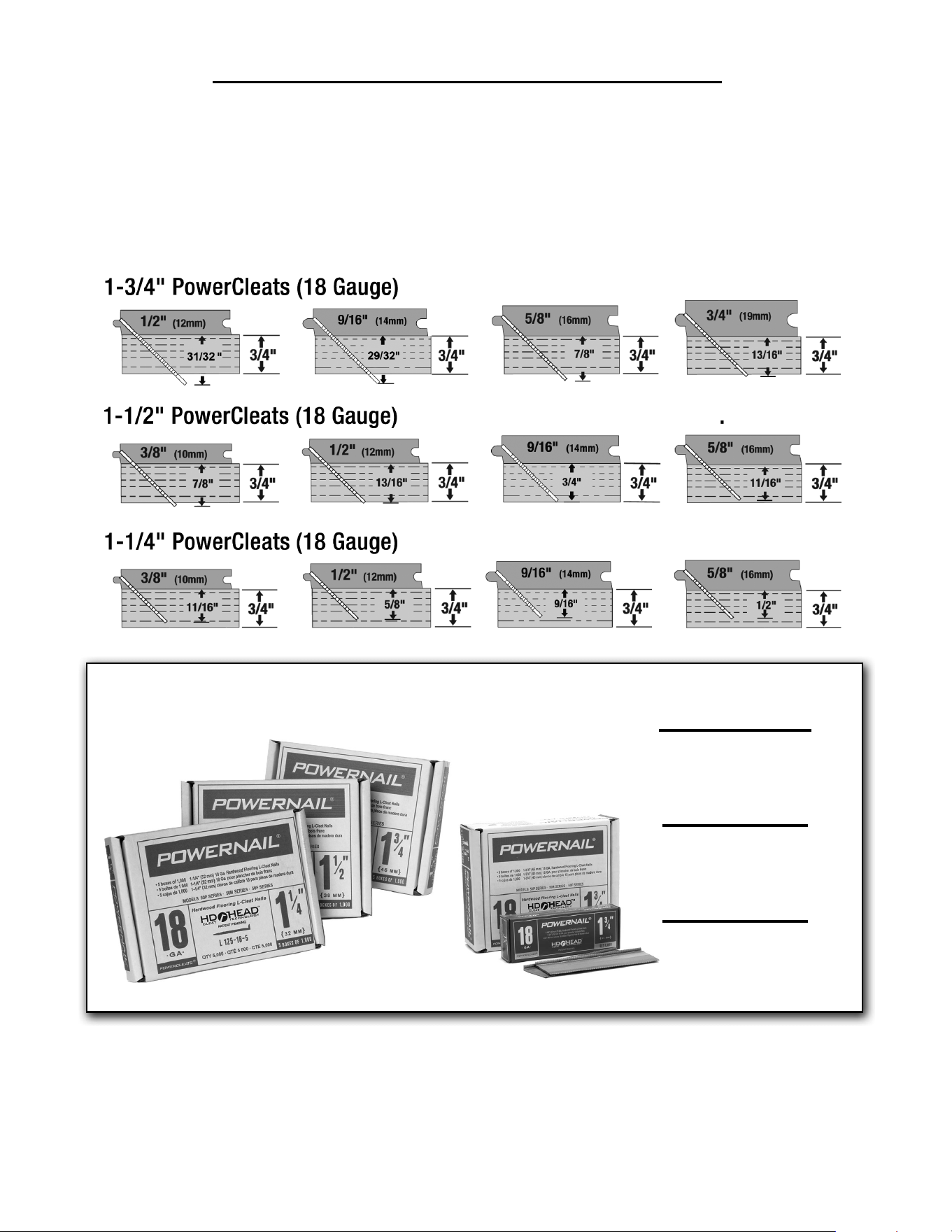
This chart will assist you in determining the proper length of Powercleats to use for
various thicknesses of fl ooring. Approximate vertical penetration of the Powercleat under
the hardwood fl oor is shown for each application. This is only a guide. Results should be
tested in the fi eld before proceeding.
POWERCLEATS LENGTH DETERMINATION CHART
Nail Penetration for 3/4" Subfl ooring.
1¼” 5 Pack
(5 x 1,000 Cleats)
Part #: L125185
1½” 5 Pack
(5 x 1,000 Cleats)
Part #: L150185
1¾” 5 Pack
(5 x 1,000 Cleats)
Part #: L175185
18 GA HD POWERCLEATS
®
12