

Visit our website at: http://www.harborfreight.com
Email our technical support at: [email protected]
Owner’s Manual & Safety Instructions
Save This Manual Keep this manual for the safety warnings and precautions, assembly,
operating, inspection, maintenance and cleaning procedures. Write the product’s serial number in the
back of the manual near the assembly diagram (or month and year of purchase if product has no number).
Keep this manual and the receipt in a safe and dry place for future reference. 21a
When unpacking, make sure that the product is intact
and undamaged. If any parts are missing or broken,
please call 1-888-866-5797 as soon as possible.
Copyright
©
2016 by Harbor Freight Tools
®
. All rights reserved.
No portion of this manual or any artwork contained herein may be reproduced in
any shape or form without the express written consent of Harbor Freight Tools.
Diagrams within this manual may not be drawn proportionally. Due to continuing
improvements, actual product may differ slightly from the product described herein.
Tools required for assembly an d se rv ic e may n ot b e in cl uded.
Read this material before using this product.
Failure to do so can result in serious injury.
SAVE THIS MANUAL.

Page 2 For technical questions, please call 1-888-866-5797. Item 63469
SaFEty OpEratiOn MaintEnancESEtup
table of contents
Safety ......................................................... 3
Specifications ............................................. 6
Setup .......................................................... 7
Operation .................................................... 9
Maintenance .............................................. 18
Parts List and Diagram .............................. 22
Warranty .................................................... 32
WarninG SyMBOLS anD DEFinitiOnS
This is the safety alert symbol. It is used to alert you to potential
personal injury hazards. Obey all safety messages that
follow this symbol to avoid possible injury or death.
Indicates a hazardous situation which, if not avoided,
will result in death or serious injury.
Indicates a hazardous situation which, if not avoided,
could result in death or serious injury.
Indicates a hazardous situation which, if not avoided,
could result in minor or moderate injury.
Addresses practices not related to personal injury.

Page 3For technical questions, please call 1-888-866-5797.Item 63469
SaFEtyOpEratiOnMaintEnancE SEtup
iMpOrtant SaFEty inFOrMatiOn
General tool Safety Warnings
read all safety warnings and instructions.
Failure to follow the warnings and instructions may result in electric shock, fire and/or serious injury.
Save all warnings and instructions for future reference.
1. KEEP GUARDS IN PLACE and in working order.
2. REMOVE ADJUSTING KEYS AND
WRENCHES. Form habit of checking to
see that keys and adjusting wrenches are
removed from tool before turning it on.
3. KEEP WORK AREA CLEAN.
Cluttered areas and benches invite accidents.
4. DON’T USE IN DANGEROUS ENVIRONMENT.
Don’t use power tools in damp or wet locations,
or expose them to rain. Keep work area well lighted.
5. KEEP CHILDREN AWAY. All visitors should
be kept safe distance from work area.
6. MAKE WORKSHOP KID PROOF with padlocks,
master switches, or by removing starter keys.
7. DON’T FORCE TOOL. It will do the job better
and safer at the rate for which it was designed.
8. USE RIGHT TOOL. Don’t force tool or attachment
to do a job for which it was not designed.
table a: rEcOMMEnDED MiniMuM WirE GauGE
FOr EXtEnSiOn cOrDS
(115-250 VOLt)
naMEpLatE
aMpErES
(at full load)
EXtEnSiOn cOrD LEnGtH
0 – 6 18 16 16 14
6.1 – 10 18 16 14 12
10.1 – 12 16 16 14 12
12.1 – 16 14 12 Do not use.
9. USE PROPER EXTENSION CORD. Make sure your
extension cord is in good condition. When using
an extension cord, be sure to use one heavy
enough to carry the current your product will draw.
An undersized cord will cause a drop in line voltage
resulting in loss of power and overheating.
Table A shows the correct size to use depending
on cord length and nameplate ampere rating.
If in doubt, use the next heavier gauge.
The smaller the gauge number, the heavier the cord.
10. WEAR PROPER APPAREL. Do not wear
loose clothing, gloves, neckties, rings, bracelets,
or other jewelry which may get caught in moving
parts. Nonslip footwear is recommended.
Wear protective hair covering to contain long hair.
11. ALWAYS USE SAFETY GLASSES. Also use
face or dust mask if cutting operation is dusty.
Everyday eyeglasses only have impact resistant
lenses, they are NOT safety glasses.
12. SECURE WORK. Use clamps or a vise to
hold work when practical. It’s safer than using your
hand and it frees both hands to operate tool.
13. DON’T OVERREACH.
Keep proper footing and balance at all times.
14. MAINTAIN TOOLS WITH CARE. Keep
tools sharp and clean for best and safest
performance. Follow instructions for
lubricating and changing accessories.
15. DISCONNECT TOOLS before servicing;
when changing accessories, such as
blades, bits, cutters, and the like.
16. REDUCE THE RISK OF UNINTENTIONAL
STARTING. Make sure switch is in
off position before plugging in.
17. USE RECOMMENDED ACCESSORIES.
Consult the owner’s manual for recommended
accessories. The use of improper accessories
may cause risk of injury to persons.
18. NEVER STAND ON TOOL.
Serious injury could occur if the tool is tipped or
if the cutting tool is unintentionally contacted.
19. CHECK DAMAGED PARTS. Before further use
of the tool, a guard or other part that is damaged
should be carefully checked to determine that
it will operate properly and perform its intended
function – check for alignment of moving parts,
binding of moving parts, breakage of parts,
mounting, and any other conditions that may
affect its operation. A guard or other part that is
damaged should be properly repaired or replaced.
20. NEVER LEAVE TOOL RUNNING UNATTENDED.
TURN POWER OFF. Don’t leave tool
until it comes to a complete stop.
Page 4 For technical questions, please call 1-888-866-5797. Item 63469
SaFEty OpEratiOn MaintEnancESEtup
Grounding instructions
tO prEVEnt ELEctric SHOcK anD DEatH FrOM incOrrEct
GrOunDinG WirE cOnnEctiOn rEaD anD FOLLOW tHESE inStructiOnS:
110-120 Vac Grounded tools: tools with three prong plugs
1. In the event of a malfunction or breakdown,
grounding provides a path of least resistance for
electric current to reduce the risk of electric shock.
This tool is equipped with an electric cord having an
equipment-grounding conductor and a grounding
plug. The plug must be plugged into a matching
outlet that is properly installed and grounded in
accordance with all local codes and ordinances.
2. Do not modify the plug provided – if it will
not fit the outlet, have the proper outlet
installed by a qualified electrician.
3. Improper connection of the equipment-grounding
conductor can result in a risk of electric shock.
The conductor with insulation having an outer
surface that is green with or without yellow
stripes is the equipment-grounding conductor.
If repair or replacement of the electric cord or
plug is necessary, do not connect the equipment-
grounding conductor to a live terminal.
4. Check with a qualified electrician or service
personnel if the grounding instructions are
not completely understood, or if in doubt as
to whether the tool is properly grounded.
5. Use only 3-wire extension cords that
have 3-prong grounding plugs and 3-pole
receptacles that accept the tool’s plug.
6. Repair or replace damaged or
worn cord immediately.
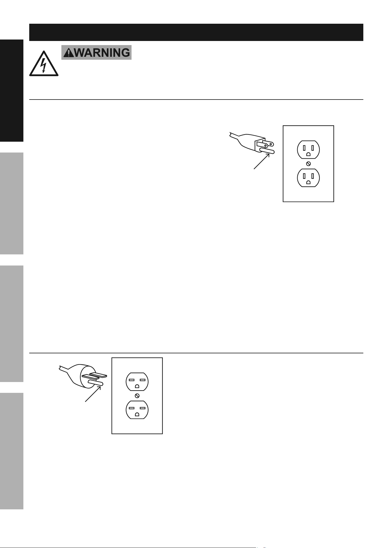
Grounding
pin
125 Vac 3-prong plug and Outlet
(for up to 125 Vac and up to 15 a)
7. This tool is intended for use on a circuit that has
an outlet that looks like the one illustrated above in
125 Vac 3-prong plug and Outlet. The tool has
a grounding plug that looks like the plug illustrated
above in 125 Vac 3-prong plug and Outlet.
8. The outlet must be properly installed and grounded
in accordance with all codes and ordinances.
9. Do not use an adapter to connect
this tool to a different outlet.
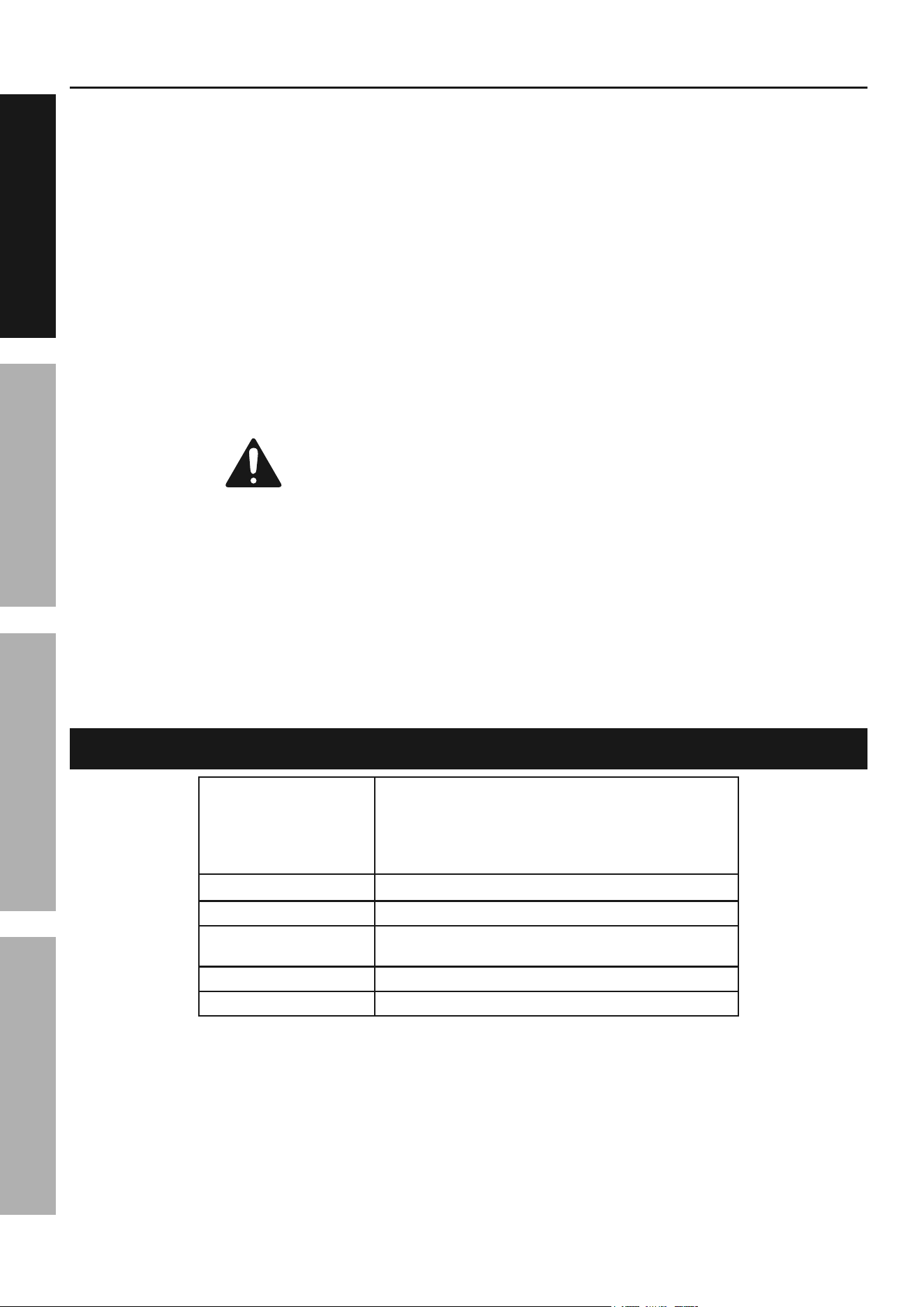
220-240 Vac tools
250 Vac 3-prong plug and Outlet
(for up to 250 Vac and up to 15 a)
Grounding
pin
1. This tool is intended for use on a circuit that has
an outlet that looks like the one illustrated above in
250 Vac 3-prong plug and Outlet.
The tool has a grounding plug
that looks like the plug illustrated above in
250 Vac 3-prong plug and Outlet.
Make sure the tool is connected to an outlet
having the same configuration as the plug.
No adapter is available or should be used with
this tool. If the tool must be reconnected for
use on a different type of electric circuit, the
reconnection should be made by qualified service
personnel; and after reconnection, the tool should
comply with all local codes and ordinances.
2. The 250 VAC plug does not come pre-installed and
will need to be installed by a certified electrician.
3. The plug above is for use on a 15 A circuit.
A different 250 VAC plug and outlet combination
may be used, provided it is rated to handle
the electrical requirements of the tool and
is installed by a certified electrician.

Page 5For technical questions, please call 1-888-866-5797.Item 63469
SaFEtyOpEratiOnMaintEnancE SEtup
Band Saw Safety Warnings
For your Own Safety read instruction
Manual Before Operating Saw
1. Wear eye protection.
2. Do not remove jammed cutoff pieces
until blade has stopped.
3. Maintain proper adjustment of blade tension,
blade guides, and thrust bearings.
4. Adjust upper guide to just clear workpiece.
5. Hold workpiece firmly against table.
6. Properly adjust the upper blade guide, blade
tension and blade guide bearings before each
use to reduce the risk of injury. See Operating
Instructions for explanation of needed adjustments.
7. Use special care when unpacking or
replacing bandsaw blade. Blade can be
under tension and may suddenly uncoil.
Wear ANSI-approved safety glasses under a
full face shield and heavy-duty work gloves.
8. Place the Band Saw on a flat, level, sturdy
surface capable of supporting the weight of the
Saw and workpieces. “Chock” the Wheels to
prevent the Band Saw from accidentally moving.
9. Before using the Band Saw, confirm the Saw Blade
is properly mounted and is not cracked or bent.
10. Do not cut more than one workpiece at a time.
11. When cutting a large workpiece, support
its entire length properly. If necessary,
use a roller stand (not included).
12. Do not lean on the Band Saw when
the tool is in its upright position.
13. When moving the Band Saw, pivot its
head to the horizontal position.
14. Bring the Saw Blade to full rotational speed
before feeding a workpiece into the Blade.
When turning off the Band Saw, allow the
Saw Blade to spin down and stop on its own.
Do not press against the Saw Blade to stop it.
15. Wear heavy-duty work gloves when
changing the Saw Blade.
16. Turn off the Band Saw and allow the Saw
Blade to completely stop if the Saw Blade is
to be backed out of an uncompleted cut.
17. Use indoors only.
18. If the teeth of the Saw Blade are so far apart that
they straddle the workpiece, severe damage to
the workpiece and/or Saw Blade will result.
19. DO nOt OpEratE WitH any GuarD
DiSaBLED, DaMaGED, Or rEMOVED. Moving
guards must move freely and close instantly.
20. The use of accessories or attachments not
recommended by the manufacturer may
result in a risk of injury to persons.
21. When servicing use only identical replacement parts.
22. Only use safety equipment that has been approved
by an appropriate standards agency. Unapproved
safety equipment may not provide adequate
protection. Eye protection must be ANSI-approved
and breathing protection must be NIOSH-approved
for the specific hazards in the work area.
23. Stay alert, watch what you are doing and use
common sense when operating a power tool.
Do not use a power tool while you are tired or
under the influence of drugs, alcohol or medication.
A moment of inattention while operating power
tools may result in serious personal injury.
24. Industrial applications must follow OSHA guidelines.
25. Maintain labels and nameplates on the tool.
These carry important safety information.
If unreadable or missing, contact
Harbor Freight Tools for a replacement.
26. Avoid unintentional starting.
Prepare to begin work before turning on the tool.
27. People with pacemakers should consult their
physician(s) before use. Electromagnetic fields in
close proximity to heart pacemaker could cause
pacemaker interference or pacemaker failure.
28. The warnings, precautions, and instructions
discussed in this instruction manual cannot cover all
possible conditions and situations that may occur.
It must be understood by the operator that
common sense and caution are factors
which cannot be built into this product,
but must be supplied by the operator.
Page 6 For technical questions, please call 1-888-866-5797. Item 63469
SaFEty OpEratiOn MaintEnancESEtup
Vibration Safety
This tool vibrates during use. Repeated or
long-term exposure to vibration may cause
temporary or permanent physical injury,
particularly to the hands, arms and shoulders.
To reduce the risk of vibration-related injury:
1. Anyone using vibrating tools regularly or for an
extended period should first be examined by a
doctor and then have regular medical check-ups
to ensure medical problems are not being caused
or worsened from use. Pregnant women or
people who have impaired blood circulation to
the hand, past hand injuries, nervous system
disorders, diabetes, or Raynaud’s Disease should
not use this tool. If you feel any medical or
physical symptoms related to vibration (such as
tingling, numbness, and white or blue fingers),
seek medical advice as soon as possible.
2. Do not smoke during use. Nicotine reduces
the blood supply to the hands and fingers,
increasing the risk of vibration-related injury.
3. Use tools with the lowest vibration when there
is a choice between different processes.
4. Include vibration-free periods each day of work.
5. Grip workpiece as lightly as possible (while still
keeping safe control of it). Let the tool do the work.
6. To reduce vibration, maintain the tool as
explained in this manual. If any abnormal
vibration occurs, stop use immediately.
SaVE tHESE inStructiOnS.
Specifications
Electrical Rating
115VAC / 60 Hz / 12 A
As wired from the manufacturer.
See pages - 31 for additional wiring options
that only a licensed electrician should attempt.
(230VAC / 60Hz / 6A wiring possible)
Motor No Load Speed 1720 RPM
Blade Speeds 90 / 135 / 195 / 255 FPM
Cutting Capacity
V-Belt Type 3V-270
Blade Size
Page 7For technical questions, please call 1-888-866-5797.Item 63469
SaFEtyOpEratiOnMaintEnancE SEtup
Setup - Before use:
read the EntirE iMpOrtant SaFEty inFOrMatiOn section at the beginning of this
manual including all text under subheadings therein before set up or use of this product.
tO prEVEnt SEriOuS inJury FrOM acciDEntaL OpEratiOn:
turn the power Switch of the tool off and unplug the tool from its electrical outlet
before performing any procedure in this section.
note: For additional information regarding the parts listed in the following pages,
refer to the Assembly Diagram near the end of this manual.
assembly/Mounting
WarninG! tO prEVEnt SEriOuS inJury:
To assemble and locate the Bandsaw will require
additional assistance and a proper lifting device.
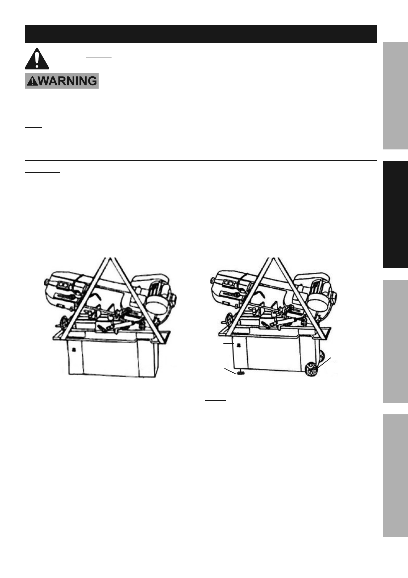
1. After the Bandsaw and its accessories
are unpacked, make sure its Head is
lowered to its horizontal position.
2. With a proper lifting device, raise the
Bandsaw approximately six inches off
the floor surface. (See Figure A.)
Figure a
3. Once the Bandsaw is lifted, insert the
Wheel Rod (92-4) through the two holes located
at the bottom/right side of the Stand (77S).
Slide one Wheel (92-2) on each end of the
Wheel Rod. Place one Washer (92-1) on each
end of the Wheel Rod. Insert one Cotter Pin
(92-3) through the hole in each end of the
Wheel Rod. Make sure to bend the Cotter Pins
to secure the Wheels in place. (See Figure B.)
4. Screw in the two Levelers (93) into the two
threaded mounting holes located underneath
the bottom/left side of the Stand.
5. Carefully lower the Bandsaw to the floor
surface. Then turn the two Levelers clockwise or
counterclockwise to properly level the Stand.
6. Attach the Hand Rod (98-1) to the Stand Assembly
using Screw (98-2), Washer (98-3) and nut (98-4).
Refer to the Diagrams shown later this manual.
WHEEL rOD
WHEEL
WaSHEr
cOttEr pin
StanD
LEVELEr
Figure B
nOtE: The Bandsaw is factory pre-wired to operate
on a grounded, 115 volt, 60 Hz, 1-Phase system. See
pages - 31 for additional wiring options that
only a licensed electrician should attempt. WarninG!
tO prEVEnt SEriOuS inJury: Only a licensed
electrician should attempt to rewire the Bandsaw.
Page 8 For technical questions, please call 1-888-866-5797. Item 63469
SaFEty OpEratiOn MaintEnancESEtup
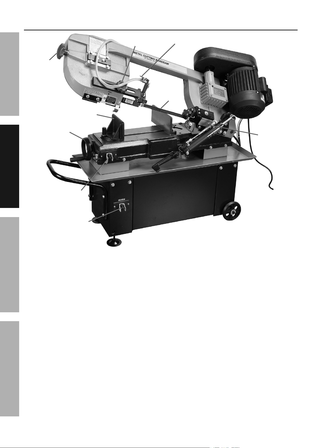
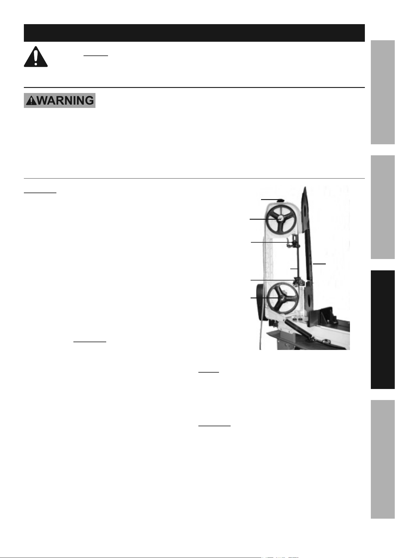
Functions
BLaDE
tEnSiOnEr
SaW
BLaDE
pOWEr
SWitcH
ViSE
HanD
WHEEL
cOOLant
puMp
SWitcH
MOVEaBLE
ViSE pLatE
FEED
cyLinDEr
cOntrOLS
aDJuStaBLE
BLaDE GuiDE
KnOB
cOOLant
VaLVE
Page 9For technical questions, please call 1-888-866-5797.Item 63469
SaFEtyOpEratiOnMaintEnancE SEtup
Operating instructions
read the EntirE iMpOrtant SaFEty inFOrMatiOn section at the beginning of this
manual including all text under subheadings therein before set up or use of this product.
tool Set up
tO prEVEnt SEriOuS inJury FrOM acciDEntaL OpEratiOn:
turn the power Switch of the tool off and unplug the tool from its electrical outlet
before performing any procedure in this section.
tO prEVEnt SEriOuS inJury:
DO nOt OpEratE WitH any GuarD DiSaBLED, DaMaGED, Or rEMOVED.
Moving guards must move freely and close instantly.
to install the Saw Blade
cautiOn! To prevent injury from the
Saw Blade (251), wear heavy duty work gloves
during blade installation and replacement.
1.
the Saw Head to its full vertical position. Then
Saw Head in place. (See Figure C.)
2. Open the Blade Back Cover (286S).
3. Release Saw Blade tension by turning
the Blade Tension Knob (245).
4. Slip the old Saw Blade off the Idler Wheel (250S),
Drive Wheel (231S), and Guide assemblies.
5. Place the new Saw Blade between each of the
Guide assemblies and around the Idler Wheel
and Drive Wheel. iMpOrtant: the teeth must
be pointing downward toward the Motor.
BLaDE tEnSiOn
KnOB
iDLEr
WHEEL
uppEr
GuiDE
aSSy.
LOWEr
GuiDE
aSSy.
DriVE
WHEEL
SaW
BLaDE
BLaDE
BacK
cOVEr
Figure c
nOtE:
Blade. Depending on material to be cut, thickness of
material, preference and wear, replace the blade. Please
refer to blade supplier literature, plus woodworker and
metal worker magazines and websites for selection.
cautiOn! If the teeth of the Saw Blade are so far
apart that they straddle the workpiece, severe damage
to the workpiece and/or Saw Blade will result.
6. Tighten the new Saw Blade by turning the
Blade Tension Knob in a clockwise direction.
7. Close the Blade Back Cover.
Page 10 For technical questions, please call 1-888-866-5797. Item 63469
SaFEty OpEratiOn MaintEnancESEtup
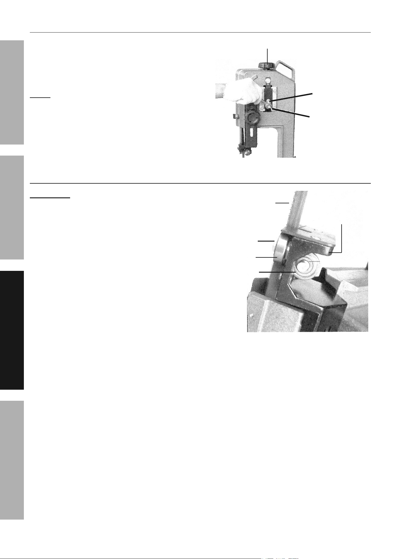
to adjust the Blade tension
Turn the Blade Tension Knob (245) clockwise to
increase tension on the Saw Blade (251). Turn the
Knob counterclockwise to decrease tension on the
Saw Blade. Correct tension is acquired when the
Saw Blade does not slip on the Drive and Idler wheels
(231S and 250S). (See Figure D and Figure C.)
nOtE: When the Bandsaw is not in use over long
periods of time, release the tension on the Saw Blade.
BLaDE tEnSiOn
KnOB
aDJuStinG
HEX HEaD ScrEW
HEX HEaD
ScrEW
Figure D
to adjust the Blade Guide Bearings
iMpOrtant: Blade Guide Bearings (266-10)
adjustment is a critical factor in the performance
of the Bandsaw. Replace the Saw Blade (251)
to see if it will correct poor cutting quality before
adjusting the Blade Guide Bearings. For example,
if a Saw Blade becomes dull on one side sooner
than the other, it will begin cutting crooked.
Replacing the Saw Blade will correct this problem,
but adjusting the Blade Guide Bearings will not.
1. If a new Saw Blade does not correct the problem,
check the clearance between the Saw Blade and
Blade Guide Bearings to obtain proper clearance.
There should only be a maximum of 0.001 clearance
between the Saw Blade and Blade Guide Bearing.
To obtain this clearance, adjust as follows:
2. The Blade Guide Bearings (266-10) are
mounted to the Guide Pivot Assemblies (270S)
and can be adjusted. (See Figure E.)
3. Loosen the Hex Socket Head Screw (269-9)
while holding the Guide Pivot Assembly
with a hex key (not included).
4. Position the Guide Pivot Assembly by turning
it to the desired position of clearance. Then
re-tighten the Hex Head Socket Screw.
5. Adjust the second Blade Guide
Bearing in the same manner.
SaW BLaDE
HEX SOcKEt HEaD
ScrEW
BLaDE GuiDE
BEarinG
BLaDE GuiDE
BEarinG
GuiDE piVOt
aSSy.
Figure E
Page 11For technical questions, please call 1-888-866-5797.Item 63469
SaFEtyOpEratiOnMaintEnancE SEtup
to adjust the Blade tracking
1. Raise the Bandsaw to its full vertical position,
making sure it locks in position by turning the
2. Turn on the Bandsaw. The Saw Blade (251) is
tracking properly when the back of the Blade is
just touching the edge of the Idler Wheel (250S)
flange. The back of the Blade should not be
rubbing against the flange. (See Figure D.)
3. If adjustment is necessary, the Blade
Guide Bearings (266-10) should be clear
of the Saw Blade. (See Figure E.)
4. Loosen the upper Hex Head Screw (243) to a point
where it is just barely snug. (See Figure D.)
5. With the Bandsaw running, turn the Adjusting Hex
Head Screw (240) until the Saw Blade is tracking
properly, making sure Blade tension is maintained
by turning the Blade Tension Knob (245) clockwise.
6. Retighten the upper Hex Head Screw
when adjustment is complete.
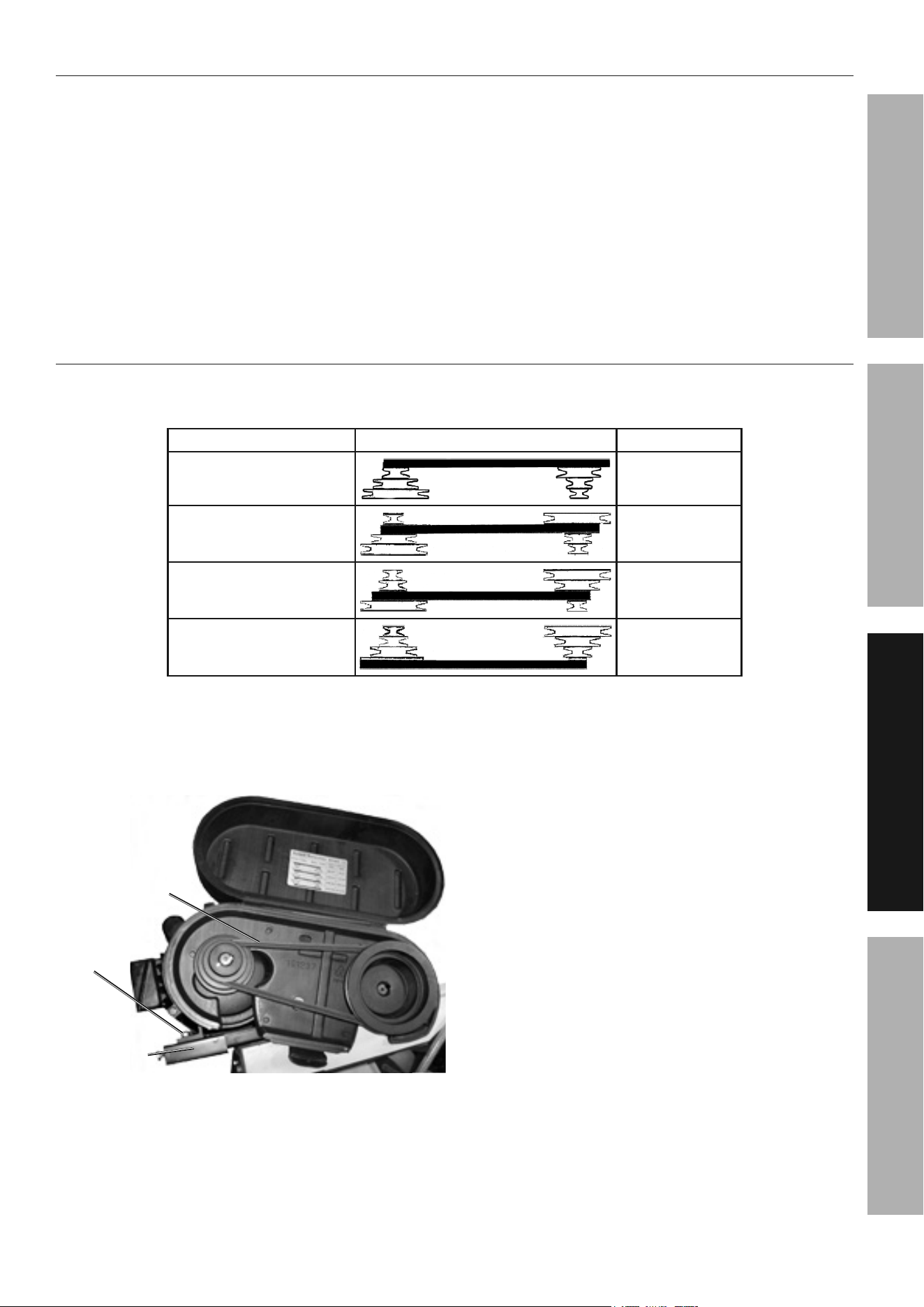
to adjust the Blade Speed
Before use, change the Saw Blade (251) speed to suit the material being cut.
The chart below shows settings for several materials.
Material Motor pulley Saw pulley Speed
Stainless Alloy Steel
Bearing Bronze
90 FpM
Medium to High Carbon Steel
Hard Brass or Bronze
135 FpM
Low to Medium Carbon Steel
Soft Brass
195 FpM
Aluminum
Plastic
255 FpM
Figure F
1. To adjust the Saw Blade speed, loosen the
two Nuts (304) and Screws (307-2). Slide the
Motor (300) forward to release tension
on the V-Belt (208). (See Figure G.)
nut
(rEMaininG
3 nutS nOt
SHOWn)
MOtOr
MOunt pLatE
V-BELt
Figure G
2. Remove the V-Belt from its two Pulleys (206, 296).
Place the V-Belt onto the two Pulleys according to
the Saw Blade speed desired. (See Figure F.)
3. Then move the Motor back to its original position
and secure in place by tightening the previously
loosened two Nuts and Screws. (See Figure G.)
4. Verify V-Belt tension by pressing the V-Belt
between the pulleys. Deflection should be
and loosen. Loosen the Nut (302) and back
off the V-Belt Tension Limiter Bolt (301).
5. Turn the V-Belt Tension Limiter Bolt
against the Motor Mount Bracket (307)
and tighten the Nut (302).
Page 12 For technical questions, please call 1-888-866-5797. Item 63469
SaFEty OpEratiOn MaintEnancESEtup
to Fill the coolant tank
nOtE: When cutting magnesium, use soluble
oils or emulsions (oil/water mix) as water only will
greatly intensify any accidental magnesium chip fire.
Contact industrial coolant supplier for specific coolant
recommendations before cutting magnesium.
1. Remove the Hose (78) at the top of the
Coolant Tank (82). Then slide the Coolant
Tank out from under the Stand (77S)
of the Bandsaw. (See Figure H.)
2. Fill the Coolant Tank to about 80% capacity with
a clean, water-soluble coolant (not included).
3. Slide the Coolant Tank back under the Stand
of the Bandsaw. Then re-insert the Hose
through the top of the Coolant Tank.
iMpOrtant: Replace the water-soluble coolant
as often as is necessary to keep metal debris
in the coolant from clogging the hoses.
HOSEHOSE
cOOLant tanK
Figure H
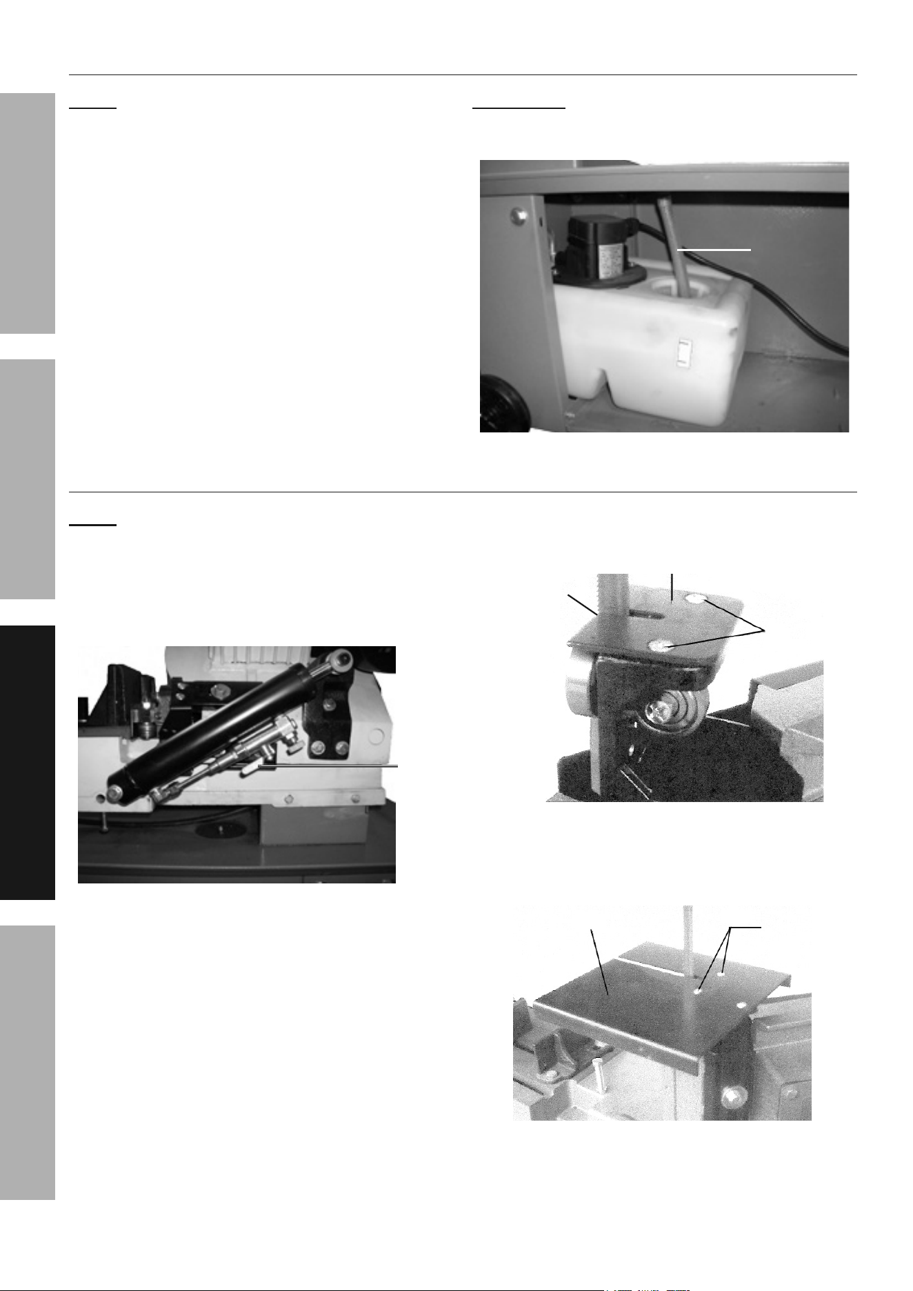
to convert the Bandsaw For Vertical use
nOtE: Notching, slitting, and contour work is best
done with the Bandsaw in its vertical position.
1. Raise the Saw Head to its full vertical
position and lock it into position by turning
the Cylinder’s Feed Lock off (position the
lever across the Cylinder). (See Figure I.)
FEED
LOcK
Figure i
2. Remove the two Screws (266-7), and remove
the Deflector Plate (266-3). (See Figure J.)
DEFLEctOr pLatE
ScrEWS
SaW BLaDE
Figure J
3. Guide the Saw Blade (251) through the slot
in the Vertical Table (55-2), and secure it in
position with the two Screws. (See Figure K.)
ScrEWS
VErticaL taBLE
Figure K

Page 13For technical questions, please call 1-888-866-5797.Item 63469
SaFEtyOpEratiOnMaintEnancE SEtup
to adjust the Feed rate
Feed rate is adjusted by the Feed Knob above
Feed Lock of the Cylinder (see Figure L).
1. Turn the Feed Knob on the Cylinder
clockwise to decrease the feed rate.
2. Turn the Feed Knob on the Cylinder
counterclockwise to increase the feed rate.
nOticE: Do not turn the Feed Knob more than
one turn at a time. Excessive feed pressure
can break the Saw Blade. Insufficient feed
pressure dulls the Saw Blade rapidly.
3. The Feed Lock locks or unlocks
Cylinder movement entirely.
FEED
LOcK
FEED
KnOB
cyLinDEr
Figure L
Page 14 For technical questions, please call 1-888-866-5797. Item 63469
SaFEty OpEratiOn MaintEnancESEtup
Workpiece and Work area Set up
1. Designate a work area that is clean and well-lit.
The work area must not allow access by children
or pets to prevent distraction and injury.
2. Route the power cord along a safe route to reach
the work area without creating a tripping hazard or
exposing the power cord to possible damage. The
power cord must reach the work area with enough
extra length to allow free movement while working.
3. Secure loose workpieces using a vise or clamps
(not included) to prevent movement while working.
4. There must not be objects, such as utility lines,
nearby that will present a hazard while working.
to use the Quick Vise
1. Place the workpiece between the Vise Jaws (9, 22)
with the amount to be cut off extending out
past the Saw Blade (251). (See Figure M.)
2. The Bandsaw is equipped with a quick action Vise
Jaw mechanism which allows you to instantly
position the moveable Front Vise Jaw (9).
3. To operate, turn the Hand Wheel (5S)
counterclockwise 1/2 turn and move the Front
Vise Jaw to the desired position. Then tighten
the Front Vise Jaw against the workpiece
by turning the Hand Wheel clockwise.
FrOnt ViSE JaW
rEar ViSE JaW
HanD WHEEL
HanD WHEEL
Figure M
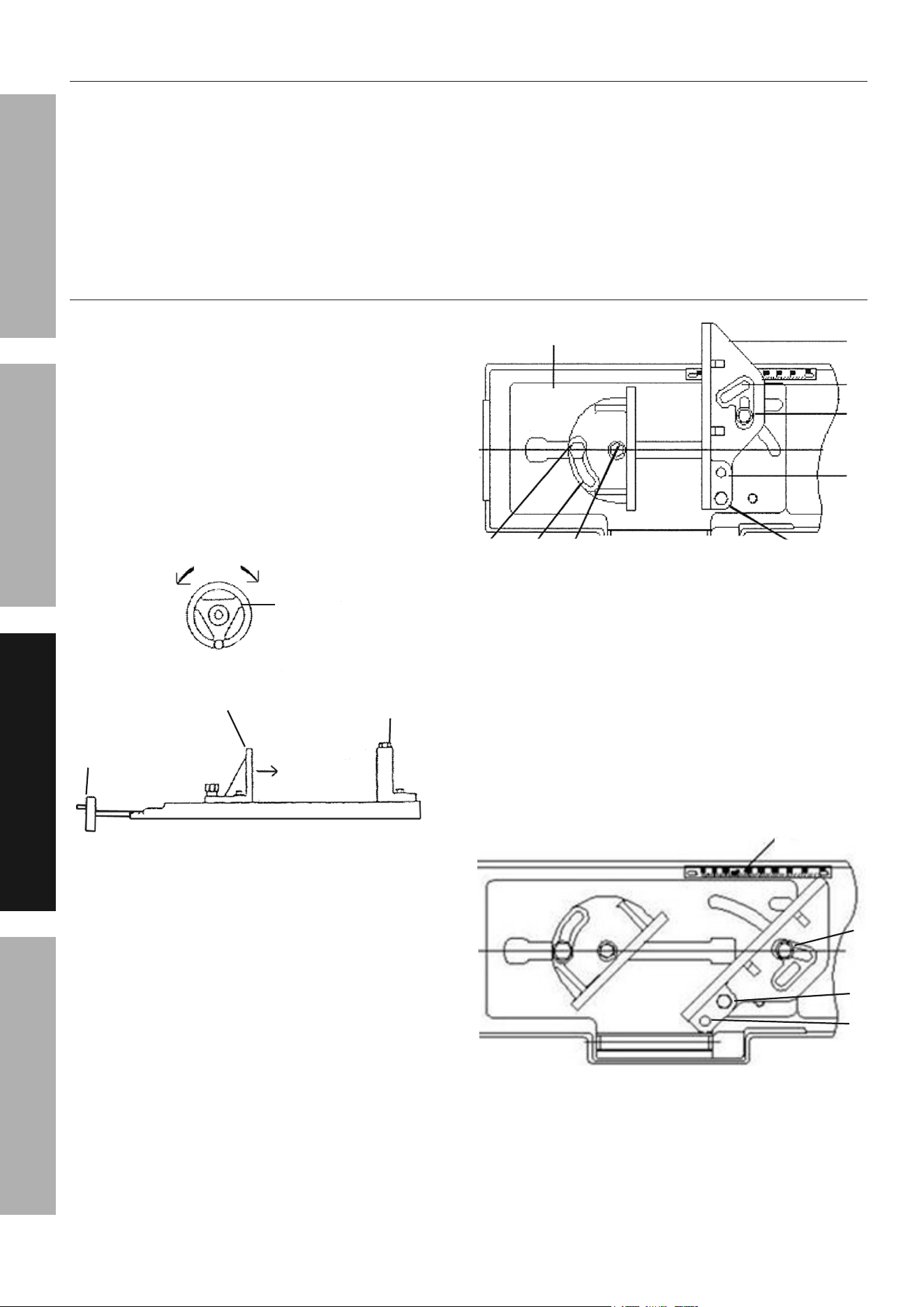
4. Setting up the Quick Vise for a straight (0°) cut:
• Loosen the Screws (H) and (G)
of Front Vise Jaw (F).
• Turn the Hand Wheel counterclockwise by half
a turn and slide back the Front Vise Jaw.
• Loosen Screw (A and B) and note that
Screw (A) should be in the slot which
is parallel with the Rear Vise Jaw.
• Rear Vise Jaw at the scale side should be
aligned with the zero (0) on the rule. Tighten
Screws (A and B). (See Figure N.)
• Free “C” slot of casting flush so the vise
can be positioned in all angles.
a
B
c
22
D
9
BaSE (1)
G H
OriGinaL pOSitiOn (FOr 0° cuttinG)
Figure n
5. Setting up the Quick Vise an angle:
• Remove Screws (A and B) from
base of the Rear Vise Jaw.
• Position (D) over (B) and attach the Screw and
Washer (19 and 22) and attach Screw (B).
• Attach Carriage Screw (17) onto Slot (C)
through the curved slot in the Base (1).
• Align edge of the Rear Vise Jaw with
the indexing rule and tighten Screws
at (B and C). (See Figure O.)
tHE pOSitiOn FOr an anGLE (45°) cut.
a
D
J
B
Figure O
6. Setting up the Quick Vise for
• Remove both fasteners from the Rear Vise Jaw.
• Position (B) over the outer
threaded hole on the Base.
Page 15For technical questions, please call 1-888-866-5797.Item 63469
SaFEtyOpEratiOnMaintEnancE SEtup
• Position Slot (A) over the small
rectangular opening across the Base.
• Attach Screws (A and B). Align the lower
edge of the Rear Vise Jaw with the “0” index
mark adjacent to the 16° degree setting.
Tighten the screws. (See Figure P)
a
D
B
Figure p
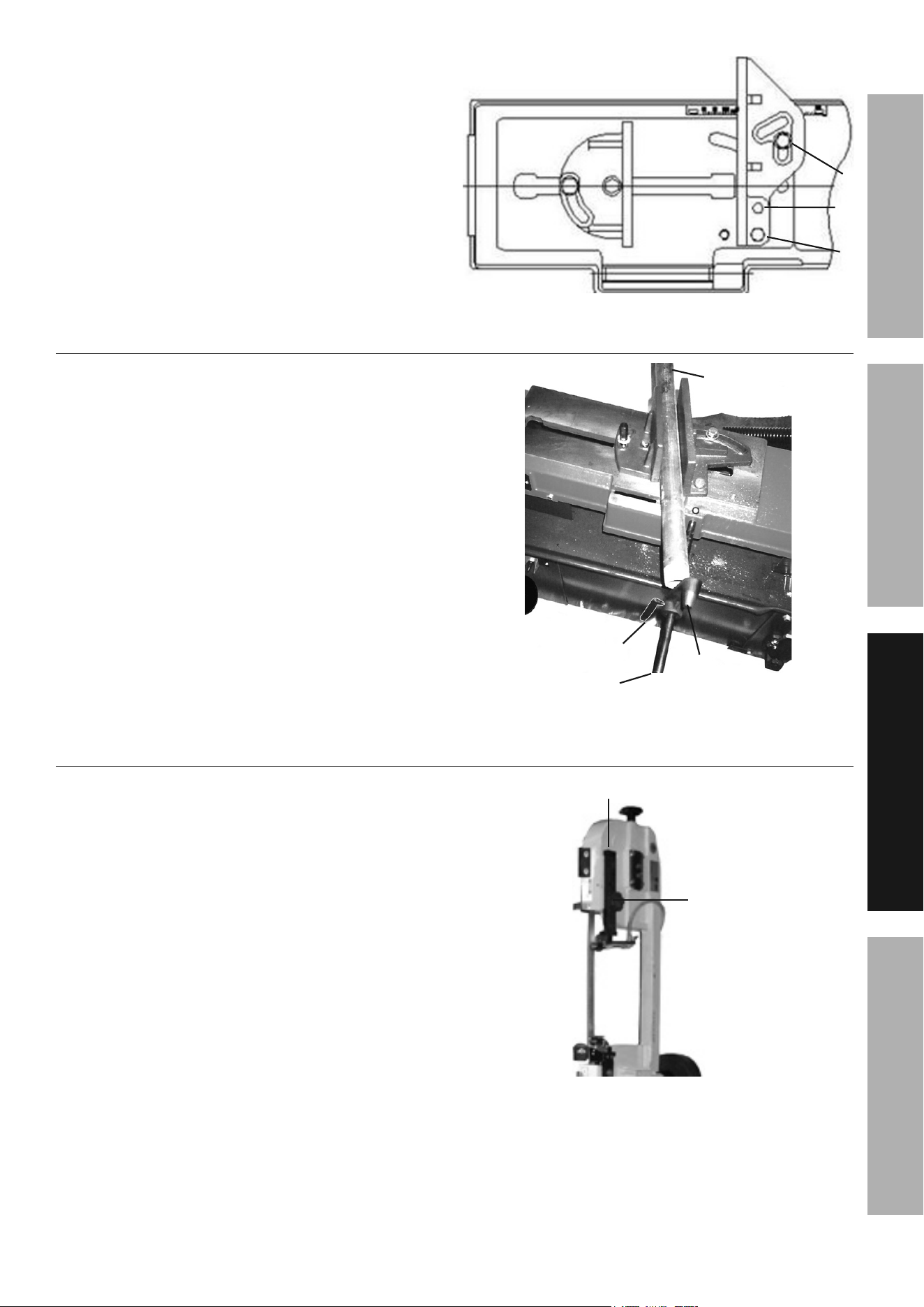
to adjust the Stop Block
For repeated cuts of pre-set lengths:
1. Loosen the Thumb Screw (38) that
holds the Stop Block (41) to the Stock
Stop Rod (40). (See Figure Q)
2. Adjust the Stop Block to the desired length
position. Then re-tighten the Thumb Screw.
tHuMB
ScrEW
StOcK
StOp rOD
StOp
BLOcK
WOrKpiEcE
(nOt
incLuDED)
Figure Q
to adjust the Blade Guide Brackets
1. The Blade Guide Knob (261) is adjusted by
loosening the Knob and sliding the Blade Guide
Bracket (269S) up or down to accommodate
the width of the workpiece. (See Figure R.)
2. The Blade Guide Bracket should be set
as close as possible to the workpiece,
without interfering with the workpiece.
3. Retighten the Blade Guide Knob.
BLaDE GuiDE BracKEt
BLaDE GuiDE
KnOB
Figure r
Page 16 For technical questions, please call 1-888-866-5797. Item 63469
SaFEty OpEratiOn MaintEnancESEtup
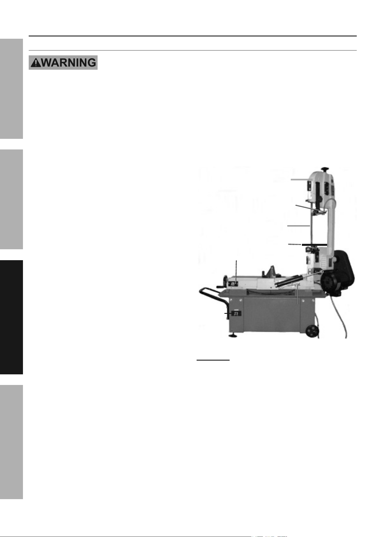
General Operating instructions
Vertical Operation
always wear anSi-approved safety impact eye goggles when operating
the Bandsaw. never wear loose fitting clothing.
When operating the machine, keep the Bandsaw Blade enclosure closed.
Do not plug the power cord into an electrical outlet until all necessary
adjustments (as previously discussed in this manual) have been made.
cut only flat workpieces when the Bandsaw is in its vertical position. never attempt
to cut pipes or other round objects with the Bandsaw in its vertical position.
Before cutting, turn on the Bandsaw and check for loose Saw Blade or machine vibration.
if this is found, turn off the Bandsaw and correct the problem before using.
always keep hands and fingers safely away from the cutting area.
1. Raise the Saw Head to its full vertical
position, making sure it locks in place by
2. Check to make sure the Motor Switch and Coolant
Pump Switch are both in their “OFF” positions.
3. Plug the Power Cord into the nearest 120 volt,
grounded, electrical outlet (or 240 volt outlet,
depending on how the Bandsaw is wired).
4. Open the Coolant Valve, then turn
the Coolant Pump Switch on.
5. Turn the Motor Switch on.
6. Set the workpiece on the Vertical Table making
sure to keep downward pressure on the
workpiece throughout the cutting process.
7. When cutting a large workpiece properly support
its entire length. If necessary, use a roller
stand (not included) with a large workpiece.
8. Allow the Saw Blade to turn up to full speed
before feeding the workpiece into the Blade.
9. Feed the workpiece into the Saw Blade
gradually. Do not force the Bandsaw to remove
material faster than it is designed to cut.
10. Use two hands and hold workpiece
securely against table at all times.
SaW
HEaD
cOOLant
VaLVE
SaW BLaDE
VErticaL taBLE
MOtOr SWitcH
cOOLant
puMp
SWitcH
CYLINDERCYLINDER
Figure S
WarninG! tO prEVEnt SEriOuS inJury:
Do not remove material stuck near the moving
parts of the Bandsaw while it is plugged in and
running. Turn off the Bandsaw if the workpiece
is to be backed out of an uncompleted cut.
11. Once the cut is made, turn Motor and Coolant Pump
Switches off and close the Coolant Valve. Then
unplug the Power Cord from its electrical outlet.
12. Wait until the Saw Blade comes to a complete
stop. Then remove the workpiece and
scrap material from the Vertical Table.
13.
Slowly lower the Saw Head to its horizontal
Lock off to lock the Saw Head in place.
Page 17For technical questions, please call 1-888-866-5797.Item 63469
SaFEtyOpEratiOnMaintEnancE SEtup
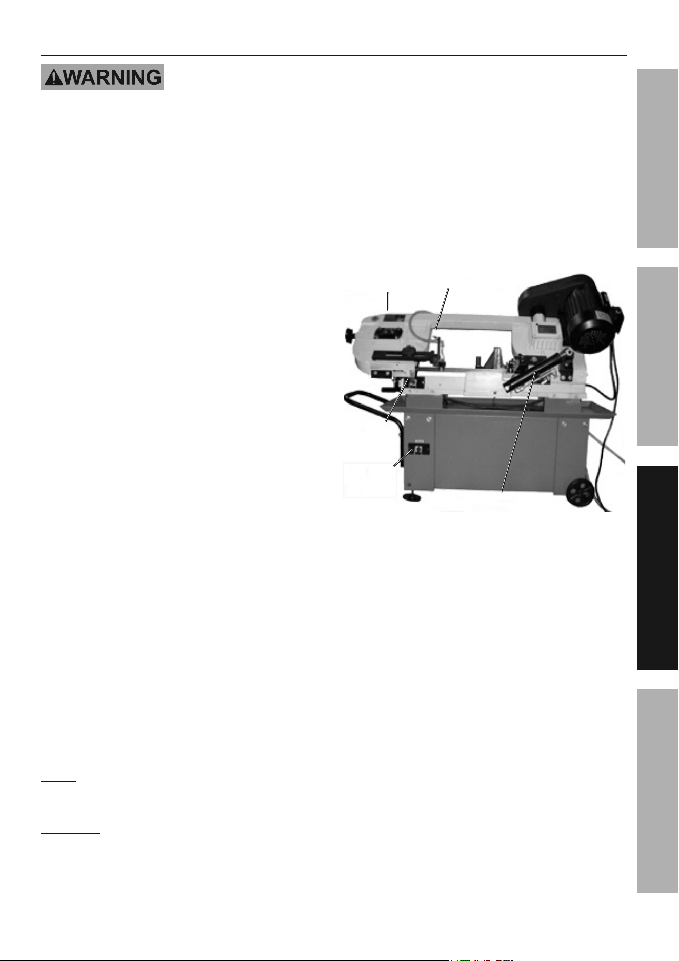
Horizontal Operation
always wear anSi-approved safety impact eye goggles when operating
the Bandsaw. never wear loose fitting clothing.
When operating the machine, keep the Bandsaw Blade enclosure closed.
Do not plug the power cord into an electrical outlet until all necessary
adjustments (as previously discussed in this manual) have been made.
Before cutting, turn on the Bandsaw and check for loose Saw Blade or machine vibration.
if this is found, turn off the Bandsaw and correct the problem before using.
always keep hands and fingers safely away from the cutting area.
1.
the Saw Head to its full vertical position.
to lock the Saw Head in place.
2. Secure the workpiece in the Vise assembly. When
cutting a large workpiece, make sure its entire
length is properly supported. If necessary, use a
roller stand (not included) with a large workpiece.
3. If cutting several workpieces at the
same length, you may wish to adjust the
Stop Block to the desired position.
4. Check to make sure the Motor Switch and Coolant
Pump Switch are both in their “OFF” positions.
5. Plug the Power Cord into the nearest 115 volt,
grounded, electrical outlet (or 230 volt outlet,
depending on how the Bandsaw is wired).
6. Open the Coolant Valve, then turn
the Coolant Pump Switch on.
7. Turn the Motor Switch on.
8.
lower the Saw Head until the Saw Blade
is just above the workpiece cut line.
9. Allow the Saw Blade to turn up to full speed
before feeding the Blade into the workpiece.
10. Use the clamp to hold the workpiece securely.
11. Through the Hydraulic Feed System, allow the Saw
Arm to lower, while it gradually feeds the Saw Blade
into the workpiece. Do not force the Bandsaw to
remove material faster than it was designed to cut.
nOtE: The speed at which the Saw Arm moves
downward may be increased or decreased by
adjusting the Feed Knob on the Cylinder.
WarninG! tO prEVEnt SEriOuS inJury:
Do not remove material stuck near the moving
parts of the Bandsaw while it is plugged in and
running. Turn off the Bandsaw if the workpiece
is to be backed out of an uncompleted cut.
cOOLant
VaLVE
SaW HEaD
cyLinDEr
cOOLant cOOLant
puMp puMp
SWitcHSWitcH
MOtOr
SWitcH
Figure t
12. IMPORTANT: When in the horizontal cutting mode
only, the Motor Switch will automatically turn to
its “OFF” position and shut off the Bandsaw’s
Motor when the cut has been completed.
13. Once the cut is made, and the motor is
switched off, turn the Coolant Pump Switch
off and close the Coolant Valve. Then unplug
the Power Cord from its electrical outlet.
14. Wait until the Saw Blade comes to a complete
stop. Then raise the Saw Head to its full vertical
to lock the Saw Head in place. Remove the
workpiece from the Vise assembly and scrap
material from the Base of the Bandsaw.
15.
lower the Saw Head to its horizontal position.
to lock the Saw Head in place.

Page 18 For technical questions, please call 1-888-866-5797. Item 63469
SaFEty OpEratiOn MaintEnancESEtup
Maintenance and Servicing
procedures not specifically explained in this manual must
be performed only by a qualified technician.
tO prEVEnt SEriOuS inJury FrOM acciDEntaL OpEratiOn:
turn the power Switch of the tool off and unplug the tool from its electrical outlet
before performing any procedure in this section.
tO prEVEnt SEriOuS inJury FrOM tOOL FaiLurE:
Do not use damaged equipment. if abnormal noise or vibration
occurs, have the problem corrected before further use.
cleaning, Maintenance, and Lubrication
1. BEFOrE EacH uSE, inspect the general
condition of the tool. Check for:
• loose hardware,
• misalignment or binding of moving parts,
• cracked or broken parts,
• damaged electrical wiring, and
• any other condition that may
affect its safe operation.
2. Periodically, wear ANSI-approved
safety goggles and NIOSH-approved
breathing protection and blow dust out of
the motor vents using dry compressed air.
3. BEFOrE EacH uSE, inspect the Saw Blade (251).
Using a dull Saw Blade will cause excessive
wear on the Motor of the Bandsaw and will
not produce a satisfactory cut. Replace
with a new Saw Blade when needed.
4. aFtEr uSE, wipe external surfaces of the tool
with clean cloth. to clean the exterior parts
of the Band Saw, use only a clean cloth and
mild detergent or mild solvent to clean the body
of the Saw. Do not immerse any electrical
part of the machine in any liquids.
cautiOn! All maintenance, service, or
repairs not mentioned in this manual must only
be performed by a qualified service technician.
WarninG! if the supply cord of this
power tool is damaged, it must be replaced
only by a qualified service technician.
Page 19For technical questions, please call 1-888-866-5797.Item 63469
SaFEtyOpEratiOnMaintEnancE SEtup
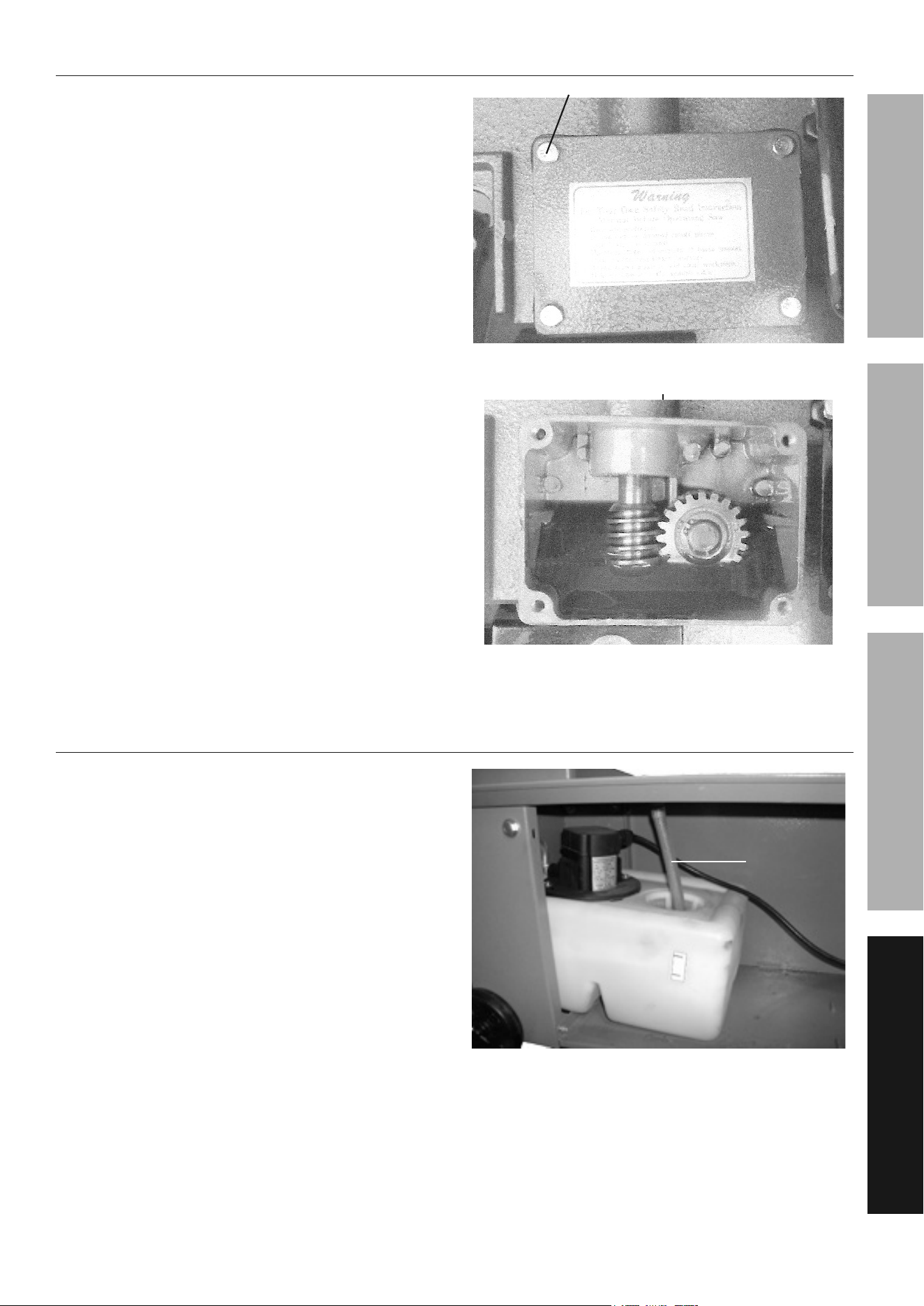
to lubricate the Worm Gear Shaft assembly
The Worm Gear Shaft Assembly (202S) runs in
an oil bath Gearbox Assembly (201S) and should
not require an oil change more than once a year,
unless the oil becomes contaminated or a leak
occurs due to improper replacement of the Gearbox
Cover. To change oil in the Gearbox Assembly:
1. Position the Saw Arm in the horizontal position.
2. Remove the four Hex Socket Head Screws, Gearbox
Cover, and Gearbox Gasket. (See Figure U.)
3. Remove the old oil from inside the Gearbox
Assembly and replace the oil using 140 weight gear
oil (not included). The new oil should just come to
the edge of the Gearbox (202-1). Do not overfill.
4. Remove the Gearbox Gasket, Gearbox
Cover, and four Hex Socket Head Screws.
(See Figure U and Figure V.)
HEX SOcKEt HEaD ScrEW
GEarBOX cOVEr
&
GEarBOX GaSKEt
Figure u
GEarBOX aSSy.
Figure V
to replace the coolant
1. Remove the Hose (78) at the top of the
Coolant Tank (82). Then slide the Coolant
Tank out from under the Stand (77S)
of the Bandsaw. (See Figure W.)
2. Fill the Coolant Tank to about 80% capacity with
a clean, water-soluble coolant (not included).
3. Slide the Coolant Tank back under the Stand
of the Bandsaw. Then re-insert the Hose
through the top of the Coolant Tank.
4. IMPORTANT: Replace the water-soluble coolant
as often as is necessary to keep metal debris
in the coolant from clogging the hoses.
HOSEHOSE
cOOLant tanK
Figure W

Page 20 For technical questions, please call 1-888-866-5797. Item 63469
SaFEty OpEratiOn MaintEnancESEtup
troubleshooting
problem possible causes Likely Solutions
Tool will not start. 1. Cord not connected.
2. No power at outlet.
3. Tool’s thermal reset breaker
tripped (if equipped).
4. Internal damage or wear. (Carbon
brushes or switch, for example.)
1. Check that cord is plugged in.
2. Check power at outlet. If outlet is unpowered,
turn off tool and check circuit breaker.
If breaker is tripped, make sure circuit is right
capacity for tool and circuit has no other loads.
3. Turn off tool and allow to cool.
Press reset button on tool.
4. Have technician service tool.
Tool operates
slowly.
Extension cord too long or
wire size too small.
Eliminate use of extension cord. If an extension cord
is needed, use one with the proper diameter for
its length and load. Table A on page 3.
Performance
decreases
over time.
1. Saw Blade dull or damaged.
2. Carbon brushes worn or damaged.
1. Replace Saw Blade. See page 9.
2. Have qualified technician replace brushes.
Excessive noise
or rattling.
Internal damage or wear. (Carbon
brushes or bearings, for example.)
Have technician service tool.
Overheating. 1. Forcing machine to work too fast.
2. Saw Blade dull or damaged.
3. Blocked motor housing vents.
4. Motor being strained by long or
small diameter extension cord.
5. Saw Blade tension is too high.
6. V-Belt tension too high.
7. Blade is too coarse or too fine for
workpiece.
8. Gear not aligned properly.
9. Gears need lubrication.
1. Allow machine to work at its own rate.
2. Replace Saw Blade. See page 9.
3. Wear ANSI-approved safety goggles and
NIOSH-approved dust mask/respirator while
blowing dust out of motor using compressed air.
4. Eliminate use of extension cord.
If an extension cord is needed, use one with
the proper diameter for its length and load.
See Table A on page 3.
5. Gradually adjust Saw Blade tension until optimal
tension has been achieved. See page 13.
6. Gradually adjust V-Belt tension until optimal
tension has been achieved. See page 11.
7. See To Install the Saw Blade on page 9
for recommended Blade type. Replace
with more appropriate Saw Blade.
8. Adjust Gears so that Worm is in center of Gear.
9. Check oil bath. See page 19.
Excessive Blade
breakage.
1. Saw Blade is loose.
2. Saw Blade turns too
quickly or too slowly.
3. Vise is not gripping the workpiece.
4. Wheel Flange is eroding Saw Blade.
5. Saw Blade teeth are spaced too
widely for the workpiece material.
6. Saw Blade is not permitted
to reach full speed before
workpiece is fed into it.
7. Blade Guides are poorly aligned.
1. Tighten Blade tension.
2. Check manual for correct Blade
speed. See page 11.
3. Clamp workpiece securely.
4. Adjust Saw Blade tracking. See page 10.
5. See To Install the Saw Blade on page 9
for recommended Blade type. Replace
with more appropriate Saw Blade.
6. Allow Blade to reach full speed before feeding
material into it.
7. Adjust Blade Guides.
Follow all safety precautions whenever diagnosing or servicing the tool.
Disconnect power supply before service.

Page 21For technical questions, please call 1-888-866-5797.Item 63469
SaFEtyOpEratiOnMaintEnancE SEtup
problem possible causes Likely Solutions
Premature
Blade dulling
1. Saw Blade teeth are spaced too
widely for the workpiece material.
2. Saw Blade turns too quickly.
3. Body Frame descends too lightly.
4. Saw Blade installed backwards.
5. Insufficient Saw Blade tension.
1. For recommended Blade type, see To Adjust
The Blade Speed on page 11 and
replace with appropriate Saw Blade.
2. Try next lower speed. See page 11.
3. Increase tension according to To Adjust
The Feed Rate on page 13.
4. Re-install Saw Blade properly.
5. Gradually increase Saw Blade tension until optimal
tension has been achieved. See page 13.
Blade cuts
crooked.
1. Vise is not square with Saw Blade.
2. Feed pressure is too great.
3. Guide Bearing is not adjusted
properly.
4. Insufficient Saw Blade tension.
5. Blade Guides are too far
from workpiece.
6. Saw Blade is dull.
7. Saw Blade turns too quickly
or too slowly for workpiece.
8. Saw Blade tracks too far away
from Wheel Flanges.
1. Adjust Vise so it is square with Blade.
Always clamp work tightly in Vise.
2. Reduce tension according to To Adjust
The Feed Rate on page 13.
3. Adjust Guide Bearing to 0.001" greater
than maximum thickness, including the
weld of the Saw. See page 10.
4. Gradually increase Saw Blade tension until optimal
tension has been achieved. See page 13.
5. Move Blade Guide as close to
workpiece as possible.
6. Replace Saw Blade. See page 9.
7. Check Manual for recommended
speeds. See page 11.
8. Adjust Saw Blade tracking. See page 10.
Blade cuts
rough.
1. Saw Blade turns too quickly.
2. Feed pressure is too heavy.
3. Saw Blade teeth are spaced too
widely for the workpiece material.
1. See page 11 for recommended speeds.
2. Reduce tension according to To Adjust
The Feed Rate on page 13.
3. Check manual for recommended Blade
type. See page 9 and replace with
more appropriate Saw Blade.
Blade twists. 1. Saw Blade is caught in
the workpiece cut.
2. Saw Blade tension is too high.
1. Reduce tension according to To Adjust
The Feed Rate on page 13.
2. Gradually adjust Saw Blade tension until optimal
tension has been achieved. See page 13.
Unusual wear
on side/back
of Blade.
1. Blade Guides are worn down.
2. Blade Guide Bearings
are out of place.
3. Blade Guide Bearing
Bracket is loose.
1. Replace Blade Guides. See page 14.
2. Adjust Blade Guide Bearings. See
3. Tighten Blade Guide Bearing Bracket
Follow all safety precautions whenever diagnosing or servicing the tool.
Disconnect power supply before service.
pLEaSE rEaD tHE FOLLOWinG carEFuLLy
THE MANUFACTURER AND/OR DISTRIBUTOR HAS PROVIDED THE PARTS LIST AND ASSEMBLY DIAGRAM
IN THIS MANUAL AS A REFERENCE TOOL ONLY. NEITHER THE MANUFACTURER OR DISTRIBUTOR
MAKES ANY REPRESENTATION OR WARRANTY OF ANY KIND TO THE BUYER THAT HE OR SHE IS
QUALIFIED TO MAKE ANY REPAIRS TO THE PRODUCT, OR THAT HE OR SHE IS QUALIFIED TO REPLACE
ANY PARTS OF THE PRODUCT. IN FACT, THE MANUFACTURER AND/OR DISTRIBUTOR EXPRESSLY
STATES THAT ALL REPAIRS AND PARTS REPLACEMENTS SHOULD BE UNDERTAKEN BY CERTIFIED AND
LICENSED TECHNICIANS, AND NOT BY THE BUYER. THE BUYER ASSUMES ALL RISK AND LIABILITY
ARISING OUT OF HIS OR HER REPAIRS TO THE ORIGINAL PRODUCT OR REPLACEMENT PARTS
THERETO, OR ARISING OUT OF HIS OR HER INSTALLATION OF REPLACEMENT PARTS THERETO.

Page 22 For technical questions, please call 1-888-866-5797. Item 63469
SaFEty OpEratiOn MaintEnancESEtup
part Description Qty
1 Cover 1
2 Acme Screw 1
3 1/2"x28xt2 Washer 1
4 5x5x15L Key 1
5S Wheel 1
7 Fixed Bolt 1
8 3/8"x25xt2 Washer 2
9 Vise Jaw Bracket (Front) 1
10 Ø5x35L Pin 1
11 Bracket 1
12S Acme Nut Assembly 1
13 Scale 1
14 3/16"x12xt0.8 Washer 2
15 3/16"x3/8"L Cross Round Head Screw 2
16 5/8" Wire Connector 1
17 1/2"x2"L Carriage Screw 1
18 1/2" Nut 1
19 1/2"x28xt2 Washer 2
20 3/8"x1-1/2"L Hex. Head Screw 1
21 1/2"x2"L Hex. Head Screw 1
22 Vise Jaw Bracket (Rear) 1
23 Bushing 1
24 Support Rod 1
25 5/16"x3/4"L Screw 1
26 Pivot Bracket 1
27 Washer 1
28 3/8"x1-1/2"L Hex. Head Screw 2
29 Support Plate 1
30 Fixed Plate 1
31 Spring 1
32 Spring Adjusting Rod 1
33 Spring Handle Bracket 1
34 5/16"x3/4"L Hex. Head Screw 1
35 5/16"x23xt2 Washer 1
35-1 5/16" Nut 1
36 3/8" Nut 1
37 3/8"x23xt2 Washer 1
38 Thumb Screw 1
39 5/16"x3/4"L Hex. Head Screw 1
40 Stock Stop Rod 1
41 Stop Block 1
42 5/16"x1-1/2"L Hex. Head Screw 1
42-1 1/4"x19xt1.5 Washer 1
45 Support Plate 1
46 3/8"x1-3/4"L Hex. Head Screw 1
47 3/8" Nut 1
48 5/16"x3/4"L Hex. Head Screw 2
49 5/16"x18xt1.5 Washer 2
50 3/8"x1-3/4"L Hex. Head Screw 1
51 3/8" Nut 1
52 5/16"x3/4"L Hex. Head Screw 2
53 5/16"x18xt1.5 Washer 2
55-1 1/4"x3/8"L Flat Cross Head Screw 1
55-2 Vertical Table 1
55-4 1/4" Nut 1
56 Warning Label 1
65 Filter 1
66 Switch Cut Off Tip 1
68 3/8"x18xt1.5 Washer 8
69 5/16" Nut 9
72 5/16"x1"L Hex. Head Screw 7
73 5/16"x1-1/4"L Hex. Head Screw 1
part Description Qty
75 3/16"x3/8"L Cross Round Head Screw 2
77S Stand Assembly 1
78 1/2" Hose 1
82 Coolant Tank 1
84S Pump 1
85 1/4"x5/8"L Cross Round Head Screw 2
86 1/4"x19xt1.5 Washer 2
88 3/8"PTx5/16" Coupler 1
89 5/8" Hose Clip 2
90 5/16"x2000 Hose 1
91S Fitting 1
92-1 3/8" Washer 2
92-2 Wheel 2
92-3 Ø3x25L Cotter Pin 2
92-4 Wheel Rod 1
93 Coaster of Stand 2
98-1 Hand Rod 1
98-2 5/16"x1-1/2"L Hex. Head Screw 4
98-3 5/16"x18xt1.5 Washer 8
98-4 5/16" Nut 4
130 Bracket 1
130 Bracket 1
131 M4x5L Cross Round Head Screw 4
132 Switch Base 1
132 Switch base 1
133 M5 Washer 2
134 M4x10L Cross Round Head Screw 2
135 5/16"x23xt3 Washer 1
136 5/16"x3/4"L Hex. Head Screw 1
139 Washer 1
140 Cylinder Lower Support 1
141 5/16"x19xt1.5 Washer 1
142 5/16"x1/2"L Hex. Head Screw 1
201S Gearbox Assembly 1
202S Worm Gear Shaft Assembly 1
203 5x5x30L Key 1
206 Spindle Pulley 1
207 1/4"x3/8"L Hex. Socket Headless Screw 2
208 3Vx270 V-Belt 1
209 Cover 1
210 3/8" Nut 1
211 3/8"x20xt2 Washer 1
212 Cylinder Upper Support 1
213 5/16"x18xt1.5 Washer 3
214 5/16"x1"L Hex. Head Screw 3
215 3/8"x23xt2 Washer 2
216 RF-712N Cylinder Complete Set 1
217 3/8"x2-1/4"L Hex. Socket Head Screw 1
218 Body Frame 1
219 3/8"Spring Washer 4
220 3/8"x1-1/4"L Hex. Head Screw 4
230 S25C - Retaining Ring 1
231S Drive Wheel 1
232 6x6x20L Key 1
233 5/16"x3/4"L Hex. Head Screw 1
234 1/4"x5/8"L Cross Socket Hex. Head Screw 2
235 1/4"x16xt1.5 Washer 2
236 Support Plate 1
237 Sliding Plate 2
238 Blade Tension Sliding Block 1
239 5/16"x3/4"L Hex. Socket Headless Screw 1
240 5/16"x1-1/2"L Hex. Head Screw 2
parts List and Diagram
parts List

Page 23For technical questions, please call 1-888-866-5797.Item 63469
SaFEtyOpEratiOnMaintEnancE SEtup
record product’s Serial number Here:
note: If product has no serial number, record month and year of purchase instead.
note: Some parts are listed and shown for illustration purposes only, and are not available
individually as replacement parts. Specify UPC 792363634694 when ordering parts.
part Description Qty
241 5/16"x12xt2 Washer 2
242 5/16" Spring Washer 4
243 5/16"×3/4"L Hex. Head Screw 4
244 Spring 1
245 Blade Tension Knob 1
246 3/8"x25xt2 Washer 1
249S Shaft Assembly 1
250S Idler Wheel Assembly 1
251 0.032"x3/4"x93"x6-10T Blade 1
252 Switch Cut Off Tip 1
253 1/4"x16xt1.5 Washer 1
254 1/4"x5/8"L Cross Socket Hex. Head Screw 1
255 3/8"x1-1/4"L Hex. Head Screw 1
256 3/8"x25xt2 Washer 1
258S Brush Assembly 1
259 3/16"x3/8"L Cross Round Head Screw 2
261 Blade Guide Knob 1
262 3/8"x25xt2 Washer 1
266S Blade Guide Bracket (Rear) 1
267S Guide Pivot Assembly 1
268S Bearing Shaft Assembly 1
269S Blade Guide Bracket (Front) 1
270S Guide Pivot Assembly 1
271S Bearing Shaft Assembly 1
279 Blade Cover (Front) 1
280 5/32"x1/4"L Cross Round Head Screw 2
284 Plum handle 2
285 1/4"x16xt1.5 Washer 2
286S Blade Back Cover 1
288 1/4"x16xt1.5 Washer 4
289 1/4"x1/2"L Cross Round Head Screw 4
290 1/4"x1/2"L Cross Socket Hex. Head Screw 1
290 Plum handle 1
291 Motor Pulley Cover 1
293 1/4"x5/8"L Cross Socket Hex. Head Screw 2
294 1/4"x19xt1.5 Washer 2
295 5x5x30L Key 1
296 Motor Pulley 1
297 1/4"x3/8"L Hex. Socket Headless Screw 1
298 5/16"x3/4"L Carriage Screw 4
300 Motor 1
301 5/16"x1"L Hex Head Screw 2
302 5/16" Nut 2
303 Motor Mount Plate 1
304 5/16" Nut 4
305 5/16"x3/4"L Hex. Head Screw 4
part Description Qty
306 5/16"x23xt2 Washer 12
307 Motor Mount Bracket 1
307-1 5/16"X23Xt2 Washer 2
307-2 5/16"X7/8"L Hex. Head Screw 2
343 1/4"x16xt1.5 Washer 1
345 Emergency Switch Bracket 1
348 M6x12L Cross Round Head Screw 4
351 3/16"x3/8"L Hex. Socket Head Screw 2
600 Knob 1
601 Knob 1
602 1/4"x1/2"L Hex. Socket Headless Screw 1
603 Pressure Lump 1
604 Ø12xt2 Washer 1
605 3/8"x1-1/4"L Hex. Head Screw 2
606 3/8"x20xt2 Washer 2
608 Pressure Shaft 1
609 Knob w/Shaft 1
610 RF31\Round Knob 1
611 Bearing 1
612 Ø12xt2 Washer 1
613 Spring 1
614 Acme Screw 1
615 Acme Nut 1
616 1/2"x28xt2 Washer 1
750 Switch Assembly 1
750-1 Switch Cover 1
750-2 Switch Cover 1
750-3 1 Switch Assembly 1
750-3 3 Switch 1
750-4 3/16"x3/8"L Screw 2
750-5 Cover 1
750-6 Rubber Plate 1
750-7 Electrical Box 1
750-8 5/32"x1/8"L Screw 2
750-9 5/8" Wire Connector 2
750-10 1/2" Wire Connector 2
751 Switch Assembly 1
751-1 Switch Cover 1
751-2 Switch Cover 1
751-3 3/16"x3/8"L Screw 2
751-4 Cover 1
751-5 Switch Assembly 1
751-6 Electrical Box 1
751-7 5/32"x1/8"L Screw 2
751-8 1/2" Wire Connector 1
Page 24 For technical questions, please call 1-888-866-5797. Item 63469
SaFEty OpEratiOn MaintEnancESEtup
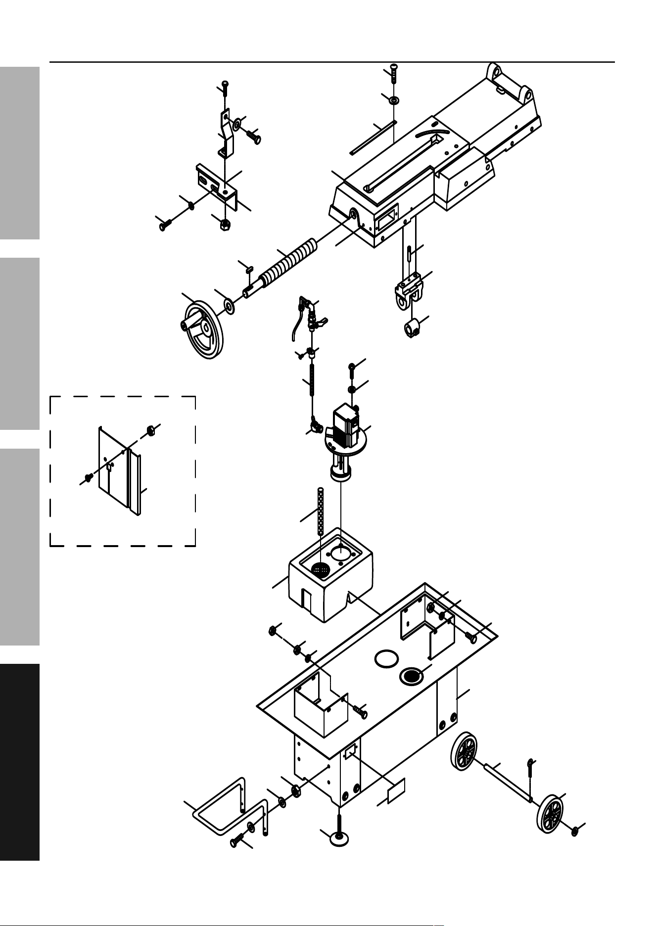
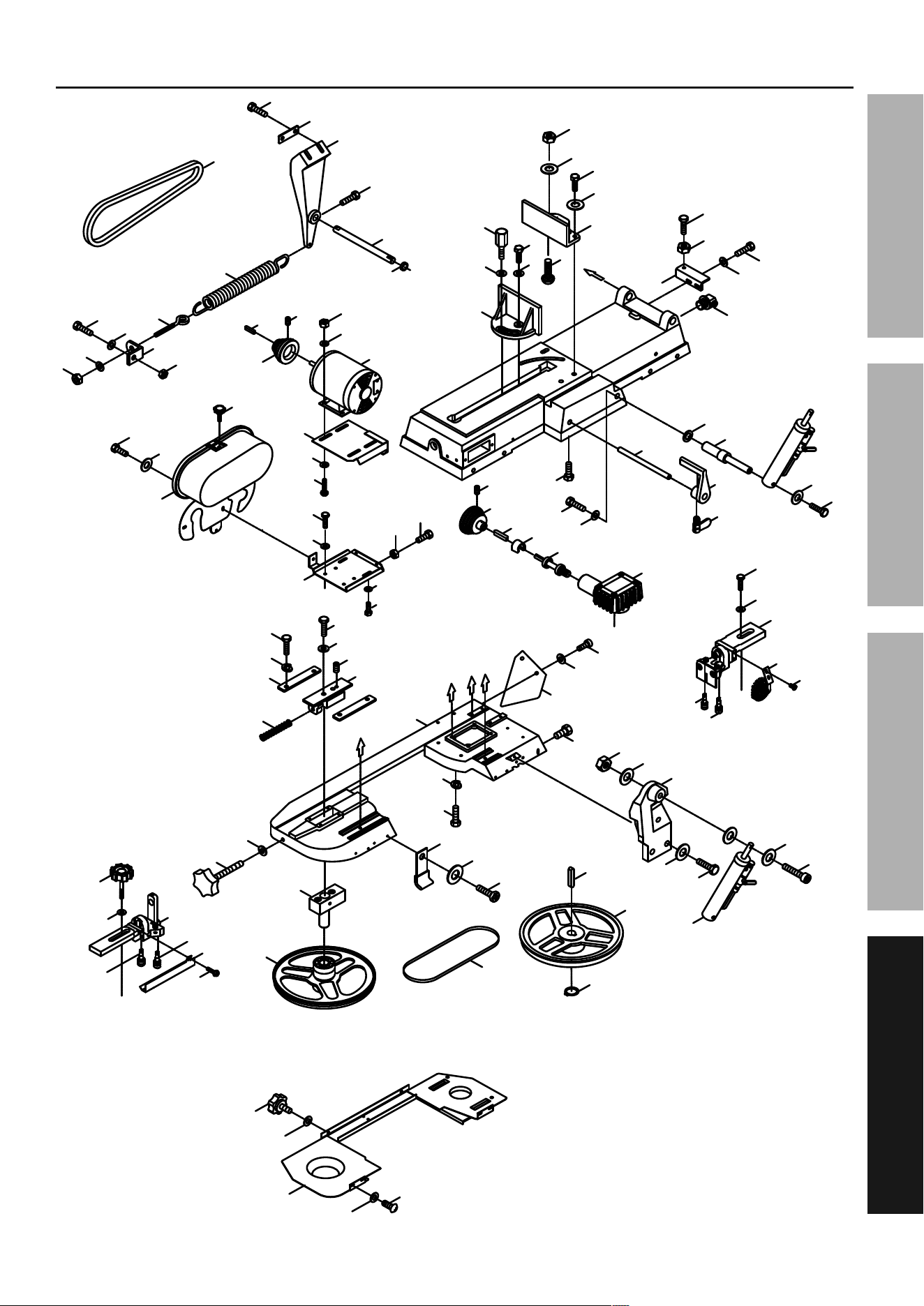
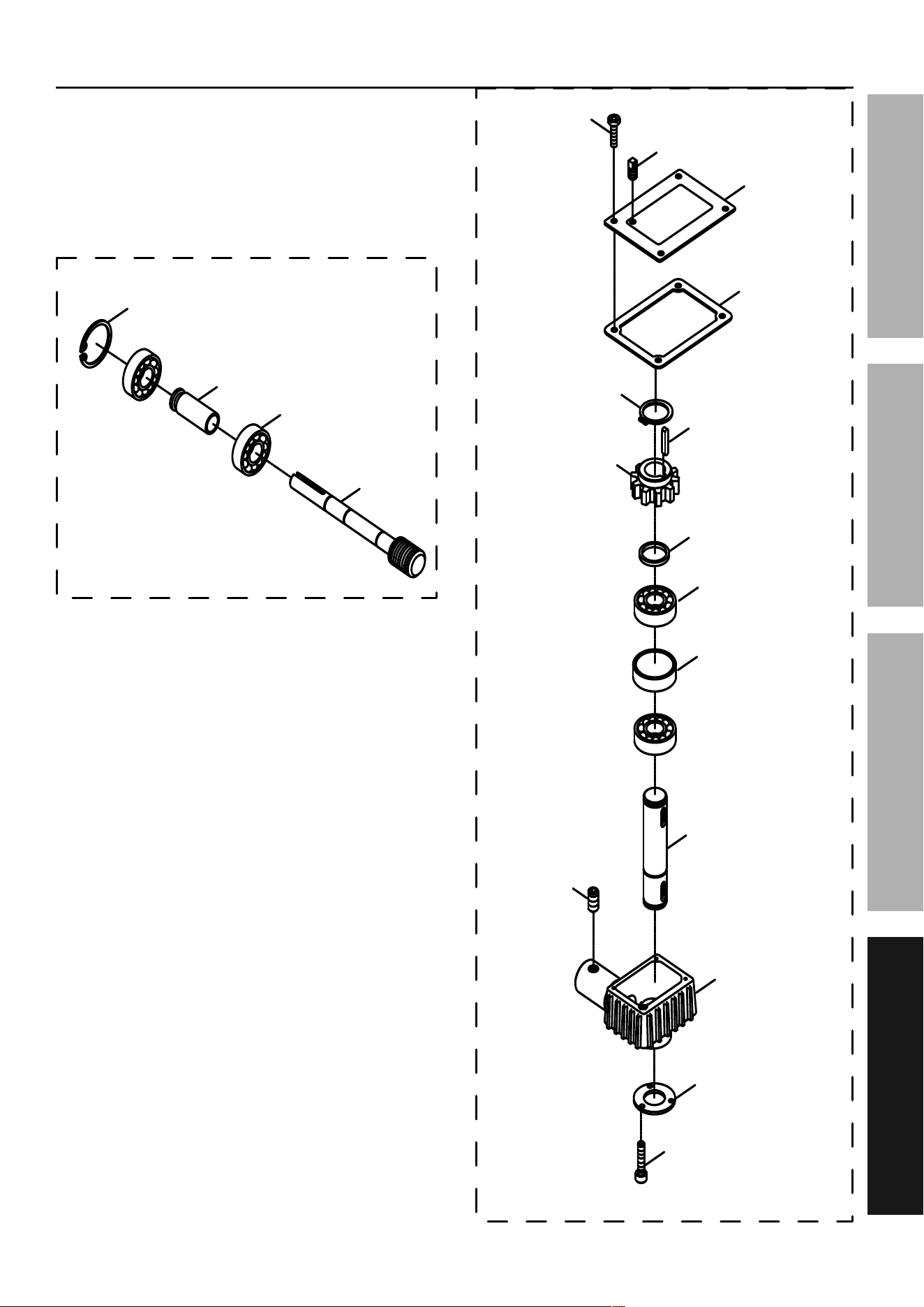
assembly Diagrams
E
E
86(2)
84S
82
93(2)
98-1
56
98-2(4)
98-4(4)
98-3(8)
73
69
69
68
88
78
85(2)
90
5S
75(2)
89(2)
91S
3
42
48(2)
45
47
2
4
49(2)
30
1
13
42-1
46
14(2)
15(2)
92-1(2)
92-2(2)
92-4
92-3(2)
77S
65
72(7)
68(7)
69(7)
12S
10
11
55-1
55-2
55-4
Page 25For technical questions, please call 1-888-866-5797.Item 63469
SaFEtyOpEratiOnMaintEnancE SEtup
assembly Diagrams - continued
C
C
B
A
F
F
B
A
F
F
16
52(2)
53(2)
29
50
51
291
201S
280(2)
271S
279
270S
269S
262
250S
251
230
231S
216
249S
261
245
246
254
253
252
220(4)
219(4)
242(4)
239
237(2)
244
218
238
307
243(4)
307-2(2)
307-1(2)
240(2)
241(2)
215(2)
213(3)
232
214(3)
217
233
210
211
212
234(2)
259(2)
258S
236
235(2)
268S
267S
266S
256
20
209
136
290
306(4)
305(4)
206
203
302(2)
301(2)
298(4)
306(4)
303
294(2)
293(2)
207(2)
35
296
36
37
35-1
33
306(4)
300
295
34
32
31
297
304(4)
9
8
8
23
202S
135
38
255
142
139
140
39
41
40
141
17
24
25
7
28(2)
208
27
26
21
22
19
18
19
289(4)
284(2)
288(4)
286S
285(2)
Page 26 For technical questions, please call 1-888-866-5797. Item 63469
SaFEty OpEratiOn MaintEnancESEtup
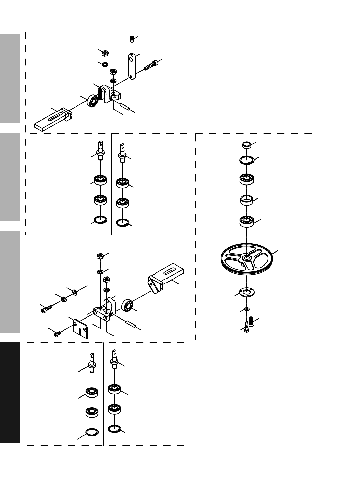
assembly Diagrams - continued
268-2(2)
268S
267-3
268-3
267S
250-3
271-1
250-8
250-9
250-6
267-2(2)
268-1
267-1
266-6
266-3
266-7(2)
266-10
266-11
266-2
266-5
266-4
266-1
250S
250-7(3)
271S
266S
266-8(2)
266-9(2)
271-3
270-3
270S
270-2(2)
271-2(2)
270-1
250-4(2)
250-1
250-5
269-7
269S
269-1
269-3
269-4
269-2
269-6(2)
269-5(2)
269-9
269-8
250-2
Page 27For technical questions, please call 1-888-866-5797.Item 63469
SaFEtyOpEratiOnMaintEnancE SEtup
assembly Diagrams - continued
201S
202S
201-15
202-1
201-14
202-3(2)
202-2
201-7
201-10(4)
202-4
201-13(3)
201-12
201-1
201-2
201-4
201-5(2)
201-3
201-6
201-8
201-9
201-11
Page 28 For technical questions, please call 1-888-866-5797. Item 63469
SaFEty OpEratiOn MaintEnancESEtup
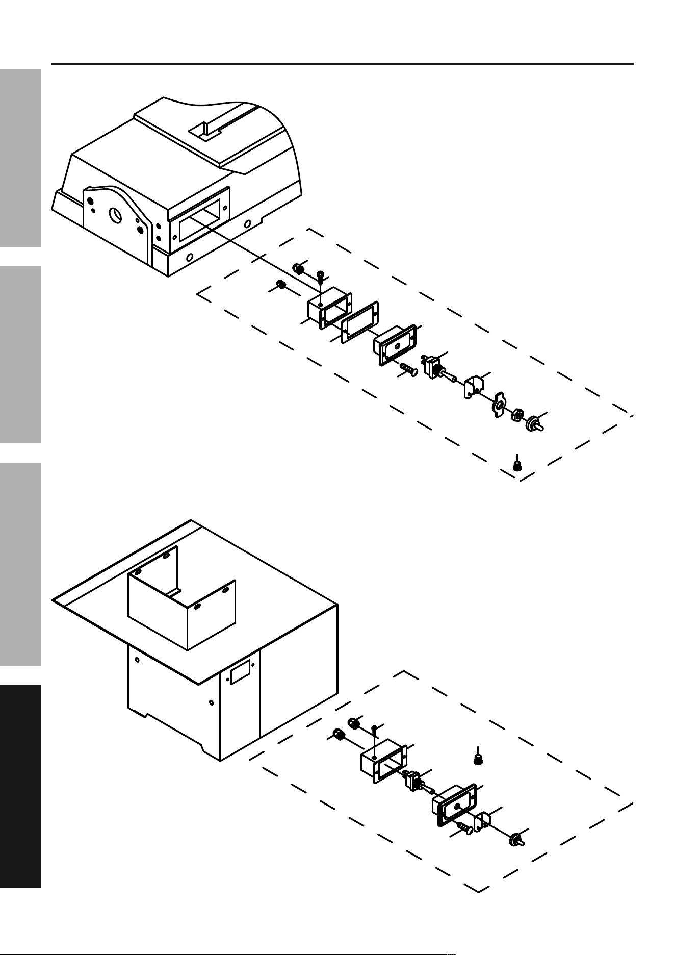
assembly Diagrams - continued
751-2
751-4
751-3(2)
751-5
751-9
751-7(2)
751-6
751
751-1
751-9
751-8(2)
750-3
750-6
750-5
750-11
750-8(2)
750-2
750-4(2)
750-7
750-9
750-1
750-10(3)
750
Page 29For technical questions, please call 1-888-866-5797.Item 63469
SaFEtyOpEratiOnMaintEnancE SEtup
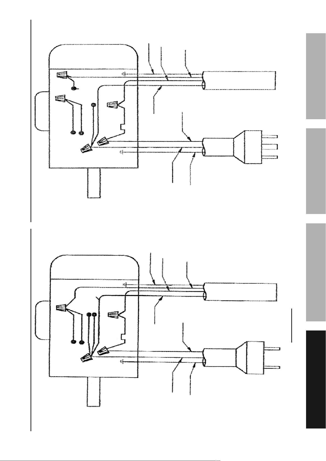
115Vac Electrical Schematic
MOtOr
Black
Black
Black
White
White
Green
Green
red
red
13a
(Overload)
230Vac Electrical Schematic
MOtOr
Grey
Black
Black
White
White
Green
Green
red
red
7a
(Overload)
Black
WarninG! to prevent serious injury and death from electrocution or fire,
only a licensed electrician should attempt to rewire this machine.
Page 30 For technical questions, please call 1-888-866-5797. Item 63469
SaFEty OpEratiOn MaintEnancESEtup
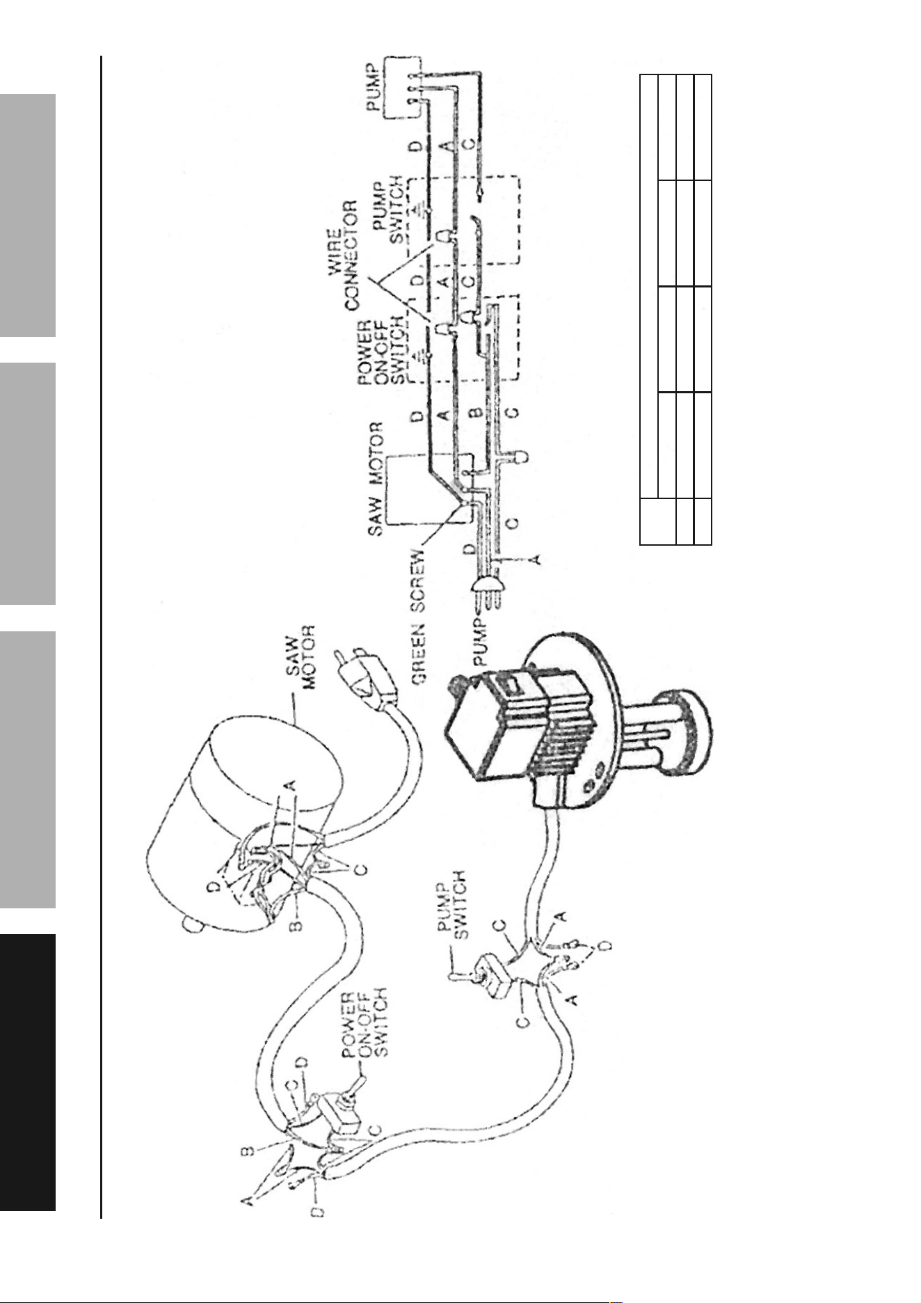
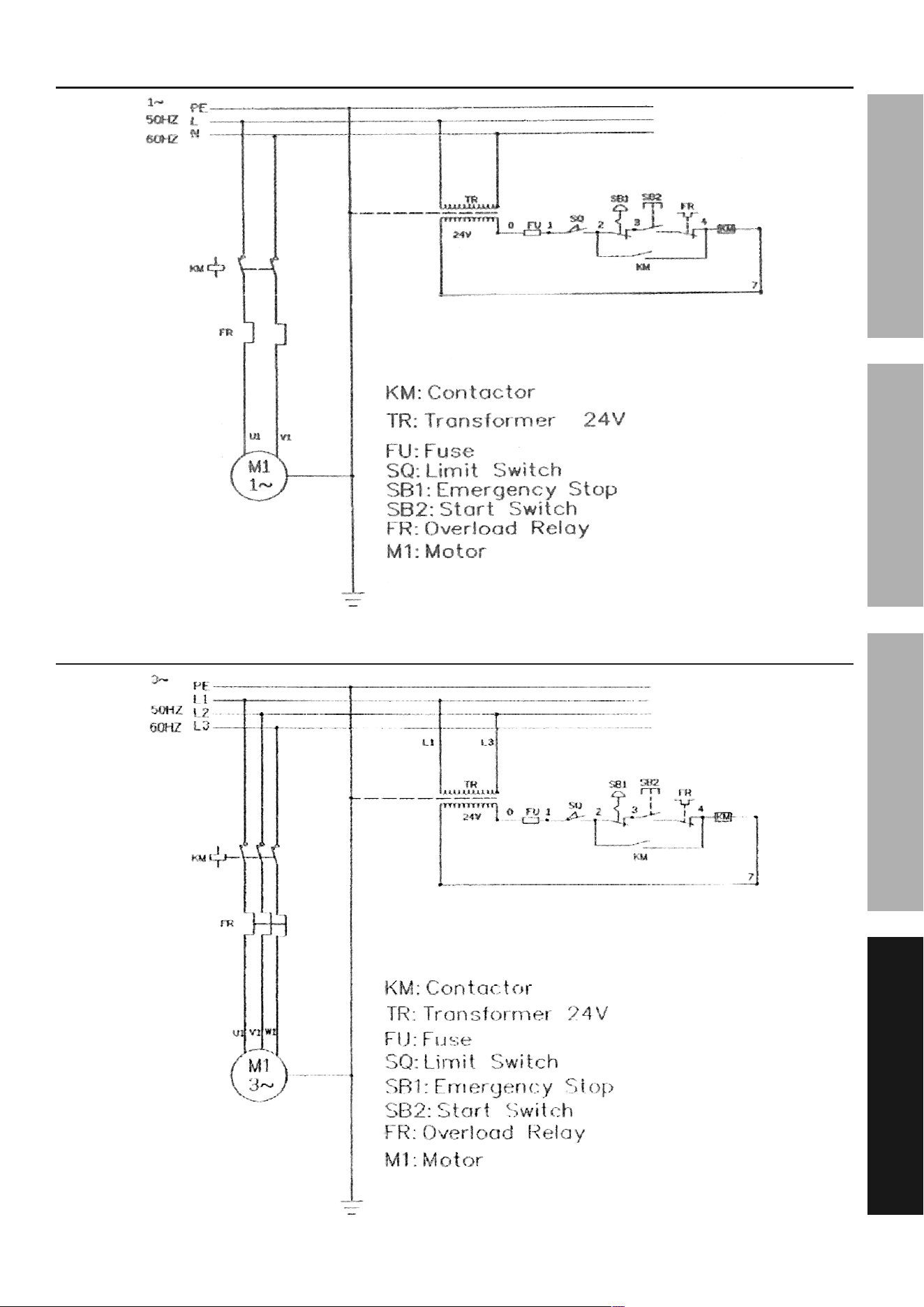
Frequency Electrical Schematic
Hz
Wire color
a B c D
50 Blue Black Brown Yellow Green
60 White Red Black Green
Page 31For technical questions, please call 1-888-866-5797.Item 63469
SaFEtyOpEratiOnMaintEnancE SEtup
1 phase Electrical Schematic
3 phase Electrical Schematic

Limited 90 Day Warranty
Harbor Freight Tools Co. makes every effort to assure that its products meet high quality and durability standards,
and warrants to the original purchaser that this product is free from defects in materials and workmanship for the
period of 90 days from the date of purchase. This warranty does not apply to damage due directly or indirectly,
to misuse, abuse, negligence or accidents, repairs or alterations outside our facilities, criminal activity, improper
installation, normal wear and tear, or to lack of maintenance. We shall in no event be liable for death, injuries
to persons or property, or for incidental, contingent, special or consequential damages arising from the use of
our product. Some states do not allow the exclusion or limitation of incidental or consequential damages, so the
above limitation of exclusion may not apply to you. THIS WARRANTY IS EXPRESSLY IN LIEU OF ALL OTHER
WARRANTIES, EXPRESS OR IMPLIED, INCLUDING THE WARRANTIES OF MERCHANTABILITY AND FITNESS.
To take advantage of this warranty, the product or part must be returned to us with transportation charges
prepaid. Proof of purchase date and an explanation of the complaint must accompany the merchandise.
If our inspection verifies the defect, we will either repair or replace the product at our election or we may
elect to refund the purchase price if we cannot readily and quickly provide you with a replacement. We will
return repaired products at our expense, but if we determine there is no defect, or that the defect resulted
from causes not within the scope of our warranty, then you must bear the cost of returning the product.
This warranty gives you specific legal rights and you may also have other rights which vary from state to state.
26541 agoura road • calabasas, ca 91302 • 1-888-866-5797
