
Visit our website at: http://www.harborfreight.com
Email our technical support at: productsupport@harborfreight.com
Visit our website at: http://www.harborfreight.com
Email our technical support at: productsupp[email protected]
Owner’s Manual & Safety Instructions
Save This Manual Keep this manual for the safety warnings and precautions, assembly,
operating, inspection, maintenance and cleaning procedures. Write the product’s serial number in the
back of the manual near the assembly diagram (or month and year of purchase if product has no number).
Keep this manual and the receipt in a safe and dry place for future reference. 21f
When unpacking, make sure that the product is intact
and undamaged. If any parts are missing or broken,
please call 1-888-866-5797 as soon as possible.
Copyright
©
2006 by Harbor Freight Tools
®
. All rights reserved.
No portion of this manual or any artwork contained herein may be reproduced in
any shape or form without the express written consent of Harbor Freight Tools.
Diagrams within this manual may not be drawn proportionally. Due to continuing
improvements, actual product may differ slightly from the product described herein.
Tools requ ir ed f or a ss em bl y an d se rv ice ma y no t be i nc lu ded.
Read this material before using this product.
Failure to do so can result in serious injury.
SAVE THIS MANUAL.

Page 2 For technical questions, please call 1-888-866-5797. Item 93762
SAFETY OPERATION MAINTENANCESETUP
Table of Contents
Safety ................................................ 3
Specifications .................................... 7
Setup ................................................ 8
Operation ......................................... 13
Maintenance .................................... 20
Parts List and Diagram .................... 25
Warranty .......................................... 28
WARNING SYMBOLS AND DEFINITIONS
This is the safety alert symbol. It is used to alert you to potential
personal injury hazards. Obey all safety messages that
follow this symbol to avoid possible injury or death.
Indicates a hazardous situation which, if not avoided,
will result in death or serious injury.
Indicates a hazardous situation which, if not avoided,
could result in death or serious injury.
Indicates a hazardous situation which, if not avoided,
could result in minor or moderate injury.
Addresses practices not related to personal injury.

Page 3For technical questions, please call 1-888-866-5797.Item 93762
SAFETYOPERATIONMAINTENANCE SETUP
IMPORTANT SAFETY INFORMATION
General Tool Safety Warnings
Read all safety warnings and instructions.
Failure to follow the warnings and instructions may result in electric shock, fire and/or serious injury.
Save all warnings and instructions for future reference.
1. KEEP GUARDS IN PLACE and in working order.
2. REMOVE ADJUSTING KEYS AND
WRENCHES. Form habit of checking to
see that keys and adjusting wrenches are
removed from tool before turning it on.
3. KEEP WORK AREA CLEAN.
Cluttered areas and benches invite accidents.
4. DON’T USE IN DANGEROUS ENVIRONMENT.
Don’t use power tools in damp or wet locations,
or expose them to rain. Keep work area well lighted.
5. KEEP CHILDREN AWAY. All visitors should
be kept safe distance from work area.
6. MAKE WORKSHOP KID PROOF with padlocks,
master switches, or by removing starter keys.
7. DON’T FORCE TOOL. It will do the job better
and safer at the rate for which it was designed.
8. USE RIGHT TOOL. Don’t force tool or attachment
to do a job for which it was not designed.
Table A: RECOMMENDED MINIMUM WIRE GAUGE
FOR EXTENSION CORDS
(120 VOLT)
NAMEPLATE
AMPERES
(at full load)
EXTENSION CORD
LENGTH
25′ 50′ 100′ 150′
0 – 6 18 16 16 14
6.1 – 10 18 16 14 12
10.1 – 12 16 16 14 12
12.1 – 16 14 12 Do not use.
9. USE PROPER EXTENSION CORD. Make sure
your extension cord is in good condition.
When using an extension cord, be sure to use
one heavy enough to carry the current your
product will draw. An undersized cord will
cause a drop in line voltage resulting in loss
of power and overheating. Table A shows the
correct size to use depending on cord length
and nameplate ampere rating. If in doubt, use
the next heavier gauge. The smaller the
gauge number, the heavier the cord.
10. WEAR PROPER APPAREL. Do not wear
loose clothing, gloves, neckties, rings, bracelets,
or other jewelry which may get caught in moving
parts. Nonslip footwear is recommended.
Wear protective hair covering to contain long hair.
11. ALWAYS USE SAFETY GLASSES. Also use
face or dust mask if cutting operation is dusty.
Everyday eyeglasses only have impact resistant
lenses, they are NOT safety glasses.
12. SECURE WORK. Use clamps or a vise to
hold work when practical. It’s safer than using
your hand and it frees both hands to operate tool.
13. DON’T OVERREACH.
Keep proper footing and balance at all times.
14. MAINTAIN TOOLS WITH CARE. Keep
tools sharp and clean for best and safest
performance. Follow instructions for
lubricating and changing accessories.
15. DISCONNECT TOOLS before servicing;
when changing accessories, such as
blades, bits, cutters, and the like.
16. REDUCE THE RISK OF UNINTENTIONAL
STARTING. Make sure switch is in
off position before plugging in.
17. USE RECOMMENDED ACCESSORIES.
Consult the owner’s manual for recommended
accessories. The use of improper accessories
may cause risk of injury to persons.
18. NEVER STAND ON TOOL.
Serious injury could occur if the tool is tipped or
if the cutting tool is unintentionally contacted.
19. CHECK DAMAGED PARTS. Before further use
of the tool, a guard or other part that is damaged
should be carefully checked to determine that
it will operate properly and perform its intended
function – check for alignment of moving parts,
binding of moving parts, breakage of parts,
mounting, and any other conditions that may
affect its operation. A guard or other part that is
damaged should be properly repaired or replaced.
20. DIRECTION OF FEED.
Feed work into a blade or cutter against the
direction of rotation of the blade or cutter only.
21. NEVER LEAVE TOOL RUNNING UNATTENDED.
TURN POWER OFF. Don’t leave tool
until it comes to a complete stop.

Page 4 For technical questions, please call 1-888-866-5797. Item 93762
SAFETY OPERATION MAINTENANCESETUP
Grounding Instructions
TO PREVENT ELECTRIC SHOCK AND DEATH FROM INCORRECT
GROUNDING WIRE CONNECTION READ AND FOLLOW THESE INSTRUCTIONS:
110-120 VAC Grounded Tools: Tools with Three Prong Plugs
1. In the event of a malfunction or breakdown,
grounding provides a path of least resistance for
electric current to reduce the risk of electric shock.
This tool is equipped with an electric cord having an
equipment-grounding conductor and a grounding
plug. The plug must be plugged into a matching
outlet that is properly installed and grounded in
accordance with all local codes and ordinances.
2. Do not modify the plug provided – if it will
not fit the outlet, have the proper outlet
installed by a qualified electrician.
3. Improper connection of the equipment-grounding
conductor can result in a risk of electric shock.
The conductor with insulation having an outer
surface that is green with or without yellow
stripes is the equipment-grounding conductor.
If repair or replacement of the electric cord or
plug is necessary, do not connect the equipment-
grounding conductor to a live terminal.
4. Check with a qualified electrician or service
personnel if the grounding instructions are
not completely understood, or if in doubt as
to whether the tool is properly grounded.
5. Use only 3-wire extension cords that
have 3-prong grounding plugs and 3-pole
receptacles that accept the tool’s plug.
6. Repair or replace damaged or
worn cord immediately.
Grounding
Pin
125 VAC 3-Prong Plug and Outlet
(for up to 125 VAC and up to 15 A)
7. This tool is intended for use on a circuit that has
an outlet that looks like the one illustrated above in
125 VAC 3-Prong Plug and Outlet. The tool has
a grounding plug that looks like the plug illustrated
above in 125 VAC 3-Prong Plug and Outlet.
8. The outlet must be properly installed and grounded
in accordance with all codes and ordinances.
9. Do not use an adapter to connect
this tool to a different outlet.
Band Saw Safety Warnings
For Your Own Safety Read Instruction
Manual Before Operating Saw
1. Wear eye protection.
2. Do not remove jammed cutoff pieces
until blade has stopped.
3. Maintain proper adjustment of blade tension,
blade guides, and blade guide bearings.
4. Adjust upper guide to just clear workpiece.
5. Hold workpiece firmly against table.
6. Use special care when unpacking or
replacing Band Saw blade. Blade can be
under tension and may suddenly uncoil.
Wear ANSI-approved safety glasses under a
full face shield and heavy-duty work gloves.
7. Keep hands away from cutting area and Saw Blade.
8. DO NOT OPERATE WITH ANY GUARD
DISABLED, DAMAGED, OR REMOVED. Moving
guards must move freely and close instantly.
9. Properly adjust the upper blade guide, blade
tension and blade guide bearing before each
use to reduce the risk of injury. See Operating
Instructions for explanation of needed adjustments.
10. Never leave the Band Saw unattended when it is
plugged into an electrical outlet. Turn off the tool,
and unplug it from its electrical outlet before leaving.
11. Make sure the Band Saw is located on a flat,
level, sturdy surface capable of supporting
the weight of the Saw and workpieces.
Always “chock” the Wheels to prevent the
Band Saw from accidentally moving.

Page 5For technical questions, please call 1-888-866-5797.Item 93762
SAFETYOPERATIONMAINTENANCE SETUP
12. Before using the Band Saw, check to
make sure the Saw Blade is properly
mounted and is not cracked or bent.
13. Never attempt to cut more than
one workpiece at a time.
14. Never attempt to cut freehand. Make sure the
workpiece to be cut is pressed firmly against
the Table and/or secured in the Vise.
15. When cutting a large workpiece, make sure
its entire length is properly supported. If
necessary, use a roller stand (not included).
16. Do not lean on the Band Saw when
the tool is in its upright position.
17. When moving the Band Saw, always have its
Head lowered to its horizontal position and the
Locking Pin (116) inserted in the Pivot (121).
18. Allow the Saw Blade to rotate to full speed
before feeding a workpiece into the Blade.
When turning off the Band Saw, allow the Saw
Blade to spin down and stop on its own. Do
not press against the Saw Blade to stop it.
19. Wear heavy-duty work gloves when
changing the Saw Blade.
20. Turn off the Band Saw and allow the Saw
Blade to completely stop if the Saw Blade is
to be backed out of an uncompleted cut.
21. Use indoors only.
22. If the teeth of the Saw Blade are so far apart that
they straddle the workpiece, severe damage to
the workpiece and/or Saw Blade will result.
23. The use of accessories or attachments not
recommended by the manufacturer may
result in a risk of injury to persons.
24. When servicing use only identical replacement parts.
25. Only use safety equipment that has been approved
by an appropriate standards agency. Unapproved
safety equipment may not provide adequate
protection. Eye protection must be ANSI-approved
and breathing protection must be NIOSH-approved
for the specific hazards in the work area.
26. Stay alert, watch what you are doing and use
common sense when operating a power tool.
Do not use a power tool while you are tired or
under the influence of drugs, alcohol or medication.
A moment of inattention while operating power
tools may result in serious personal injury.
27. Industrial applications must follow OSHA guidelines.
28. Maintain labels and nameplates on the tool.
These carry important safety information.
If unreadable or missing, contact
Harbor Freight Tools for a replacement.
29. Avoid unintentional starting.
Prepare to begin work before turning on the tool.
30. People with pacemakers should consult their
physician(s) before use. Electromagnetic fields in
close proximity to heart pacemaker could cause
pacemaker interference or pacemaker failure. In
addition, people with pacemakers should:
• Avoid operating alone.
• Do not use with power switch locked on.
• Properly maintain and inspect to avoid electrical
shock.
• Any power cord must be properly
grounded. Ground Fault Circuit Interrupter
(GFCI) should also be implemented – it
prevents sustained electrical shock.
31. The warnings, precautions, and instructions
discussed in this instruction manual cannot cover all
possible conditions and situations that may occur.
It must be understood by the operator that
common sense and caution are factors
which cannot be built into this product,
but must be supplied by the operator.

Page 6 For technical questions, please call 1-888-866-5797. Item 93762
SAFETY OPERATION MAINTENANCESETUP
Vibration Safety
This tool vibrates during use. Repeated or long-term exposure to vibration may cause temporary or permanent
physical injury, particularly to the hands, arms and shoulders. To reduce the risk of vibration-related injury:
1. Anyone using vibrating tools regularly or for an extended period should first be examined by
a doctor and then have regular medical check-ups to ensure medical problems are not being
caused or worsened from use. Pregnant women or people who have impaired blood circulation
to the hand, past hand injuries, nervous system disorders, diabetes, or Raynaud’s Disease should
not use this tool. If you feel any medical or physical symptoms related to vibration (such as
tingling, numbness, and white or blue fingers), seek medical advice as soon as possible.
2. Do not smoke during use. Nicotine reduces the blood supply to the hands
and fingers, increasing the risk of vibration-related injury.
3. Use tools with the lowest vibration when there is a choice between different processes.
4. Include vibration-free periods each day of work.
5. Grip workpiece as lightly as possible (while still keeping safe control of it). Let the tool do the work.
6. To reduce vibration, maintain the tool as explained in this manual. If
any abnormal vibration occurs, stop use immediately.
SAVE THESE INSTRUCTIONS.

Page 7For technical questions, please call 1-888-866-5797.Item 93762
SAFETYOPERATIONMAINTENANCE SETUP
SPECIFICATIONS
Electrical Rating 120VAC / 60Hz / 6.4A
Motor No Load Speed 1700 RPM
Blade Speeds 80 FPM / 120 FPM / 200 FPM
Cutting Capacity
4-1/2" Round Stock
4" x 6" Rectangular Stock
Throat Depth 4-1/2"
Angle Cutting Capacity
0° - 55° (Left) Miter Plate on
Horizontal Cutting Bed
Horizontal Bed 11-1/2" L x 7-1/2" W x 23-1/2" H
Vertical Bed 9-5/8" L x 9-1/2" W x 33-1/2" H
V-Belt Type 0-508
Blade Size
64-1/2" L x 1/2" W x
0.025″ Thick / 14 TPI
Page 8 For technical questions, please call 1-888-866-5797. Item 93762
SAFETY OPERATION MAINTENANCESETUP
SETUP - BEFORE USE:
Read the ENTIRE IMPORTANT SAFETY INFORMATION section at the beginning of this
manual including all text under subheadings therein before set up or use of this product.
TO PREVENT SERIOUS INJURY FROM ACCIDENTAL OPERATION:
Turn the Power Switch of the tool off and unplug the tool from its electrical outlet
before performing any procedure in this section.
NOTE: For additional information regarding the parts listed in the following
pages, refer to the Assembly Diagram near the end of this manual.
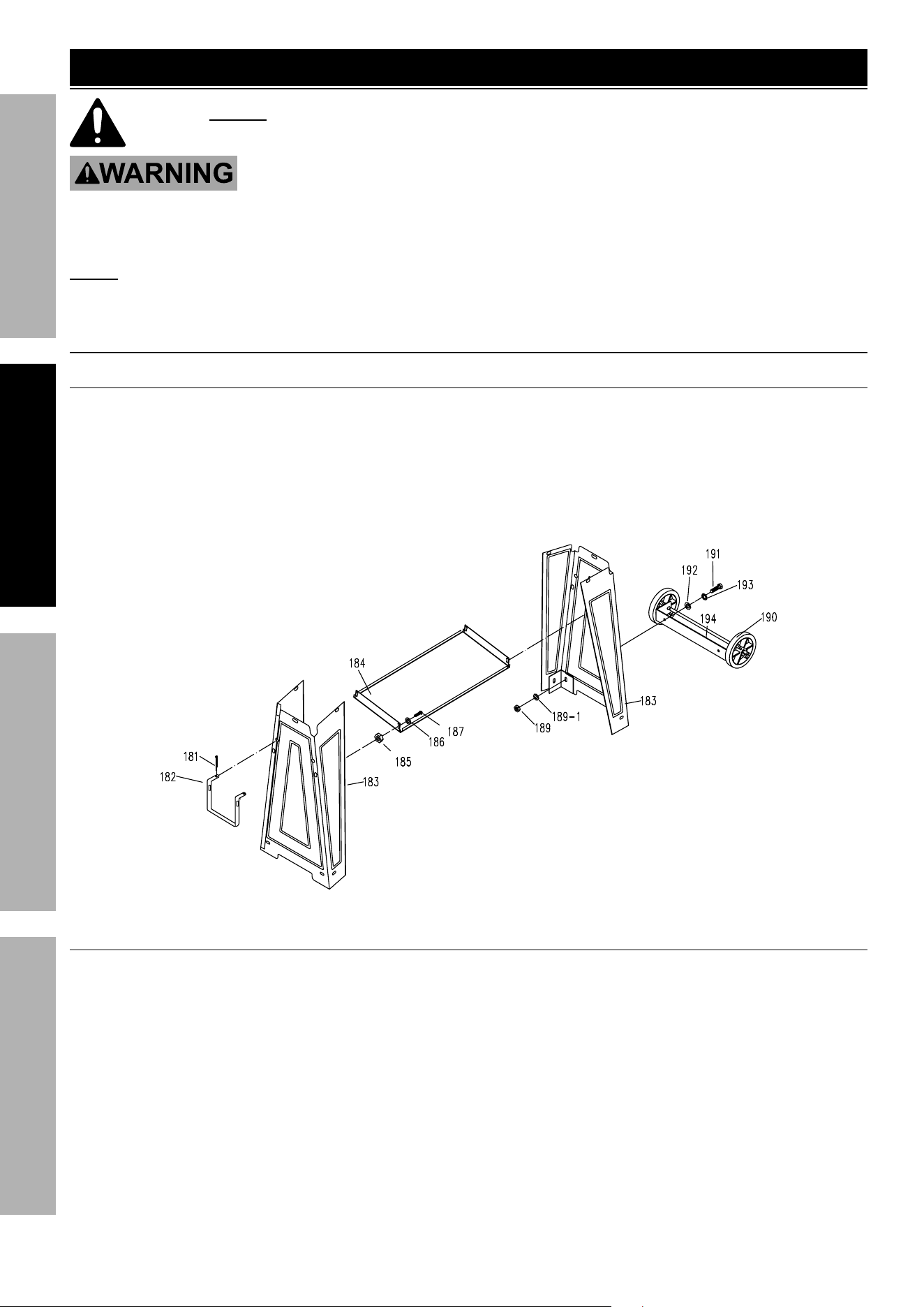
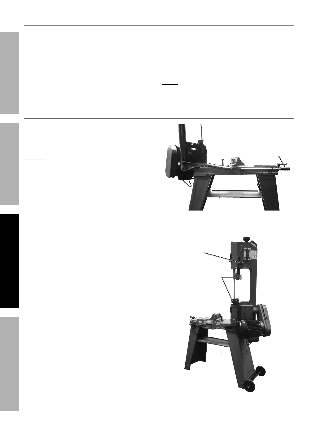
Assembly/Mounting
To Assemble the Stand
1. Insert the Pull Handle (182) into the two mounting
holes located in the upper section of one
Stand (183). Then secure the Pull Handle to the
Stand, using two Pins (181) (see Figure A).
2. Attach one end of the Tool Plate (184) to the upper
section of one Stand (183), using two Screws (187),
two Flat Washers (186), and two Nuts (185).
3. Attach the other end of the Tool Plate (184)
to the upper section of the remaining
Stand (183), using two Screws (187), two
Flat Washers (186), and two Nuts (185).
Figure A
To Attach the Wheels to the Stand
1. Align the two mounting holes in the Wheel
Bracket (194) with the two mounting
holes located in the lower section of the
Stand without the Pull Handle.
2. Secure the Wheel Bracket to the Stand,
using two Bolts (191), two Spring
Washers (193), two Flat Washers (192), two
Flat Washers (189-1), and two Nuts (189).
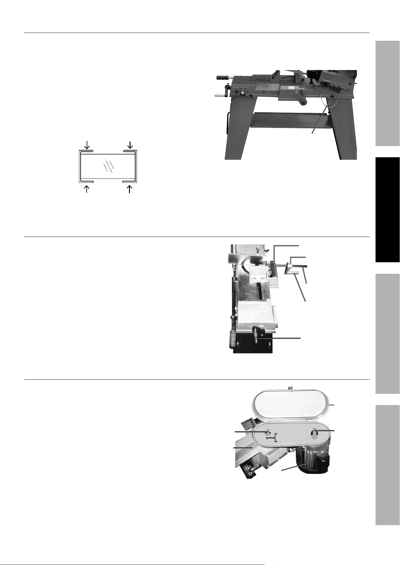
Page 9For technical questions, please call 1-888-866-5797.Item 93762
SAFETYOPERATIONMAINTENANCE SETUP
To Attach the Band Saw to the Stand
1. With assistance and an adequate lifting
device, carefully set the Band Saw on top of
the Stand assembly. Place the motor end
of the Saw at the wheeled end of the stand,
making sure the upper section of the Stand
fits outside the base of the Band Saw.
2. Align the threaded mounting holes in each
end at the base of the Band Saw with the
two mounting holes located at each end of
the Stand assembly (see Figure B).
MOUNTING
HOLE
MOUNTING
HOLE
MOUNTING
HOLE
MOUNTING
HOLE
Figure B: Stand (Top View)
3. Secure the Band Saw to the Stand
assembly, using four Screws (61) and four
Spring Washers (60) (see Figure C).
Screw (61)Screw (61)
Spring Washer (60)Spring Washer (60)
Figure C
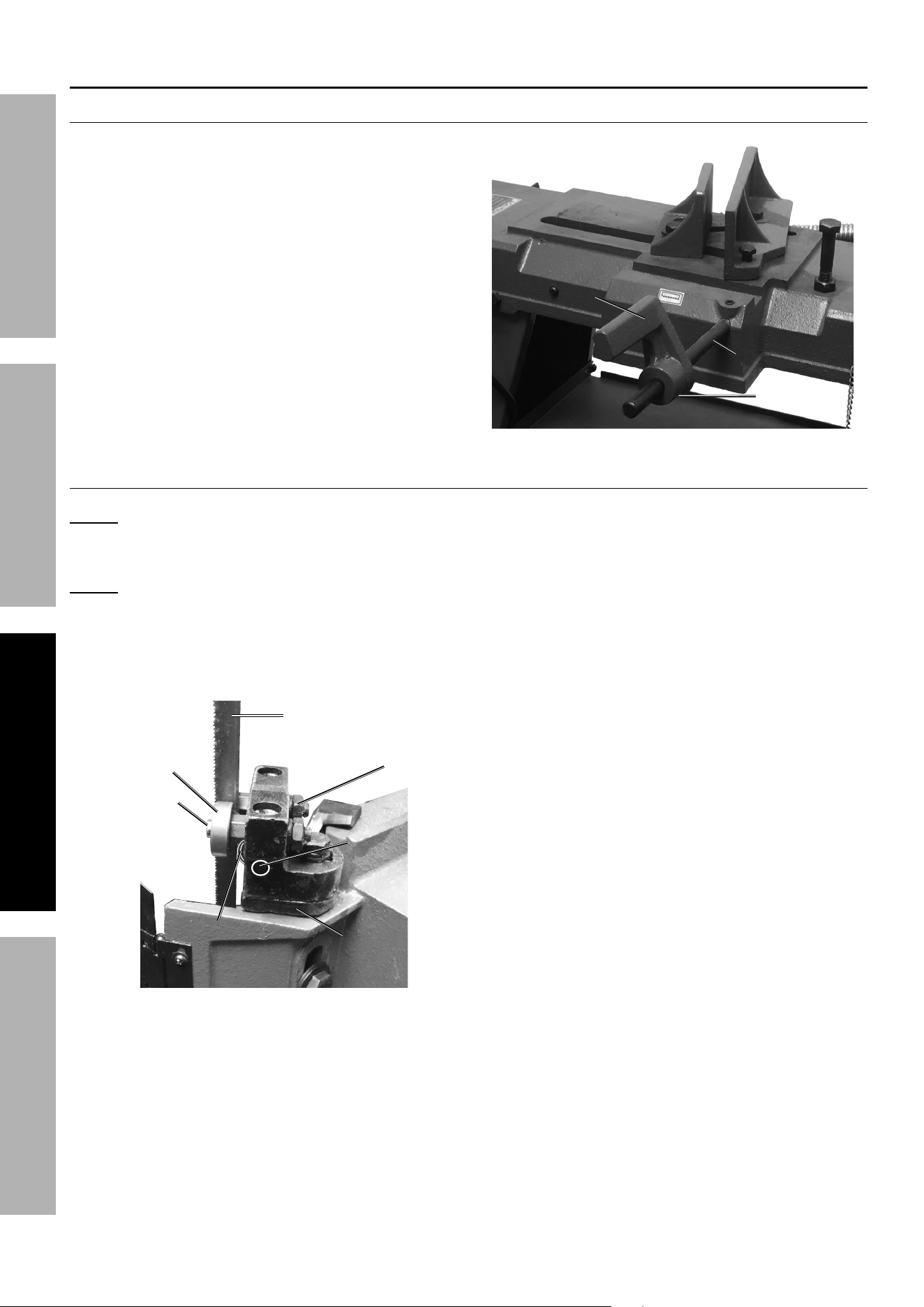
To Attach the Stock Stop Assembly
1. When mounted to the Band Saw, the
adjustable Stock Stop assembly is used to
make repetitive cuts of the same length.
2. To attach the Stock Stop (162), slide the
Shaft (163) into the mounting hole in the
Machine Bed (147), and secure the Shaft by
tightening the Set Screw (153) (see Figure D).
3. Slide the Stock Stop onto the Shaft, and secure
by tightening the Socket Head Screw (161).
Stock Stock
Stop Stop
(162)(162)
Socket Head Socket Head
Screw (161)Screw (161)
Shaft (163)Shaft (163)
Set Screw (153)Set Screw (153)
Hand Hand
Wheel Wheel
(180)(180)
Figure D
To Attach the Pulley Cover
1. Position the Pulley Cover (75) over the
Worm Shaft (12) and Motor Shaft.
2. Align the mounting hole in the Pulley Cover with
the mounting hole in the Body Frame (62).
3. Secure the Pulley Cover to the Band
Saw, using one Screw (65) and one
Spring Washer (66) (see Figure E).
Pulley Pulley
Cover (75)Cover (75)
Worm Worm
Shaft (12)Shaft (12)
Motor (82)Motor (82)
Body Body
Frame (62)Frame (62)
Screw (65)Screw (65)
Spring Washer (66)Spring Washer (66)
Motor ShaftMotor Shaft
Figure E
Page 10 For technical questions, please call 1-888-866-5797. Item 93762
SAFETY OPERATION MAINTENANCESETUP
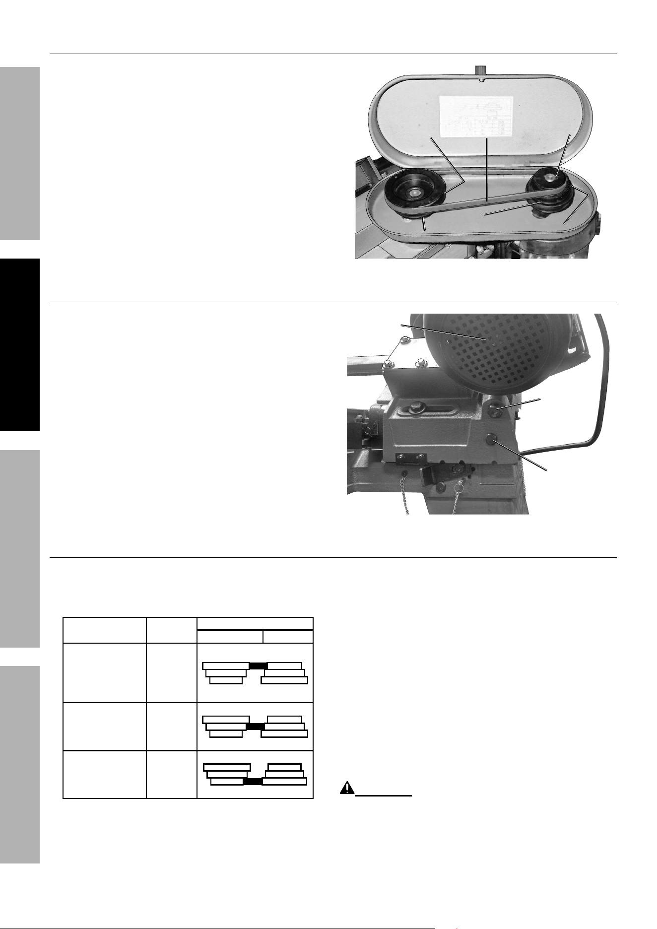
To Attach the Spindle Pulley and Motor Pulley
1. Slide the Spindle Pulley (1) fully onto the
Worm Shaft (12). Then secure the Spindle
Pulley to the Worm Shaft, using one Socket
Head Screw (2) (see Figure F).
2. Insert the Shaft Key (81) in the slot on the Motor
Shaft. Align the slot in the Motor Pulley (80) with
the Shaft Key. Slide the Motor Pulley fully onto the
Motor Shaft. Then secure the Motor Pulley to the
Motor Shaft, using one Socket Head Screw (79).
Motor Pulley (80)Motor Pulley (80)
Shaft Key (81)Shaft Key (81)
Spindle Pulley (1)Spindle Pulley (1)
V-Belt (13)V-Belt (13)
Socket Head Socket Head
Screw (2) Screw (2)
(not shown)(not shown)
Socket Head Socket Head
Screw (79) Screw (79)
(not shown)(not shown)
Figure F
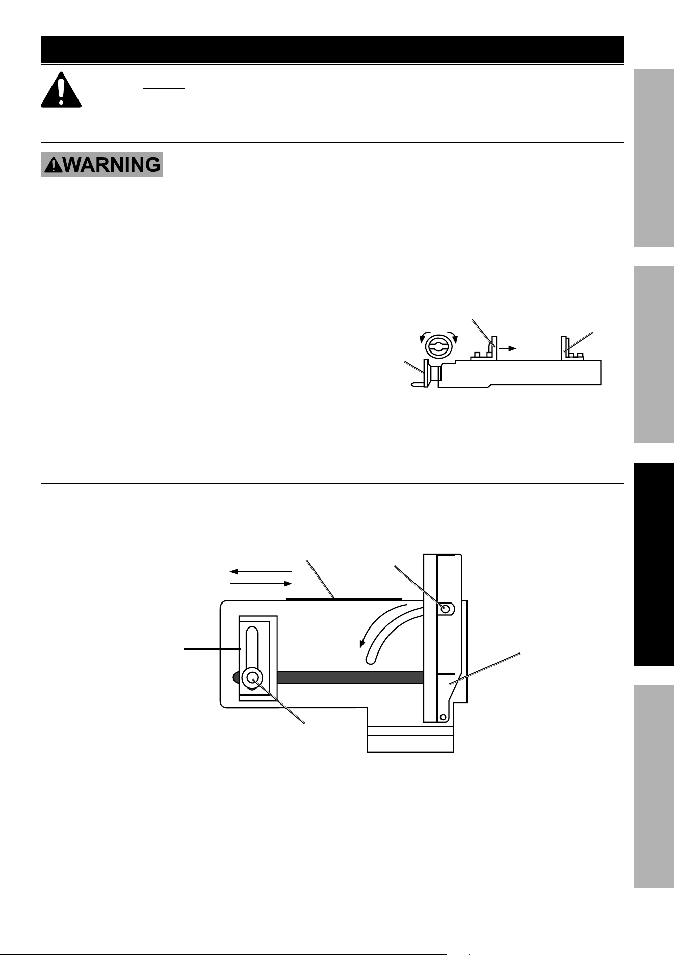
To Install the V-Belt
1. Loosen the Bolts (70 & 74) and press the
Motor (82) toward the Body (see Figure G).
2. Place the V-Belt (13) around the top
grooves in the Spindle Pulley (1) and
Motor Pulley (80) (see Figure F).
3. Adjust the position of the Motor to obtain
approximately 1/2″ depression in the V-Belt
when applying pressure with your thumb.
4. Re-tighten the Bolts to anchor the Motor in place.
Bolt (70)Bolt (70)
Motor (82)Motor (82)
Bolt (74)Bolt (74)
Figure G
To Adjust the Cutting Speed
1. The Band Saw is designed to cut at three different
speeds: 80, 120, and 200 FPM (Feet Per Minute)
depending on the type of material being cut.
MATERIAL
SPEED
(FPM)
PULLEY GROOVE
SPINDLE MOTOR
Tool Steel,
Stainless
Alloy Steels,
Bearing
Bronze
80
LARGE
SMALL
Medium to High
Carbon Steels,
Hard Brass
or Bronze
120
MEDIUM
MEDIUM
Low to Medium
Carbon Steels,
Soft Brass,
Aluminum, Plastic
200
LARGESMALL
Figure H:
2. Refer to the Chart at left to determine
the proper cutting speed for a specific
type of material being cut.
3. The cutting speed can be adjusted by
changing the position of the V-Belt:
a. Loosen the Bolts (70 & 74) and press
the Motor (82) toward the Body.
b. Place the V-Belt around the desired grooves in
the Spindle Pulley (1) and Motor Pulley (80).
c. Ease the Motor back to its original position
to tighten the tension on the V-Belt.
d. Re-tighten the Bolts to secure the Motor
in place (see Figure F, Figure G).
WARNING! Always securely close the
Lid on the Pulley Cover after installing a
V-Belt or adjusting the cutting speed.
Page 11For technical questions, please call 1-888-866-5797.Item 93762
SAFETYOPERATIONMAINTENANCE SETUP
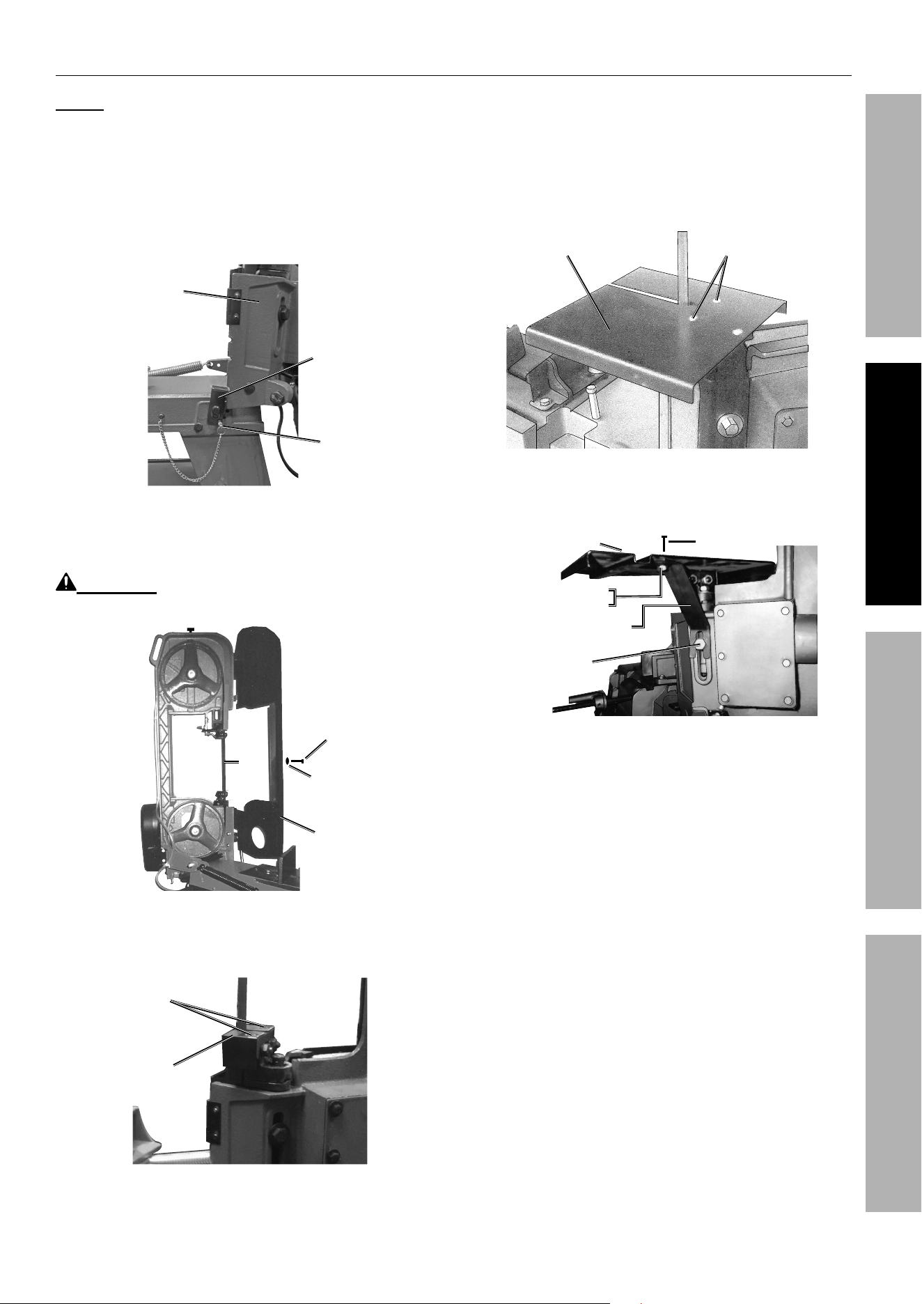
To Convert the Band Saw for Vertical Use
NOTE: Notching, slitting, and contour work is best
done with the Band Saw in its vertical position.
1. Remove the Locking Pin (116) from the Pivot (121).
2. Raise the Body Frame (62) to its full vertical position.
Turn the Support Plate (154) clockwise until it firmly
locks into the Body Frame and insert the Locking Pin
(158) to lock Body Frame into position (see Figure I).
Support Support
Plate Plate
(154)(154)
Body Body
Frame Frame
(62)(62)
Locking Locking
Pin Pin
(158)(158)
Figure I
3. Remove the Screw (113) and Flat Washer (114) to
open the Blade Back Cover (115) (see Figure J).
WARNING! TO PREVENT SERIOUS INJURY: Keep
hands and fingers safely away from the Saw Blade (83).
SawSaw
BladeBlade
(83)(83)
Blade Blade
Back Back
Cover Cover
(115)(115)
Screw Screw
(113)(113)
Flat Flat
Washer Washer
(114)(114)
Figure J
4. Remove two Screws (97) and remove the
Horizontal Cutting Guard (96) (see Figure K).
Screw (97)Screw (97)
Horizontal Horizontal
Cutting Cutting
Guard (96)Guard (96)
Figure K
5. Close the Blade Back Cover and secure
with the Screw and Flat Washer.
6. Guide the Saw Blade through the slot in
the Vertical Cutting Table (197), and secure
the Vertical Cutting Table in position with
the two Screws (97) (see Figure L).
Screw (97)Screw (97)
Vertical Cutting Table (197)Vertical Cutting Table (197)
Figure L
7. To mount the Vertical Cutting Table Support:
Bolt (63)Bolt (63)
Vertical Cutting Vertical Cutting
Table (197)Table (197)
Screw (198)Screw (198)
Flat Washer (200)Flat Washer (200)
Nut (201)Nut (201)
Vertical Cutting Vertical Cutting
Table Support (199)Table Support (199)
Figure M
a. Insert one Screw (198) downward through the
mounting hole in the Vertical Cutting Table (197).
b. Attach the top section of the Vertical Cutting
Table Support (199) to the Vertical Cutting Table
using one Flat Washer (200) and one Nut (201).
c. Loosen the Bolt (63).
d. Position the Vertical Cutting Table
Support between the Body Frame
and the head of the Bolt.
e. Firmly re-tighten the Bolt (see Figure M).
Page 12 For technical questions, please call 1-888-866-5797. Item 93762
SAFETY OPERATION MAINTENANCESETUP
To Convert the Band Saw for Horizontal Use
1. Remove the screws (97) holding the
Vertical Cutting Table (197) in place.
2. Loosen the Bolt (63) and guide the Vertical Cutting
Table Support assembly away from the Saw Blade.
3. Remove the Screw (113) and Flat Washer (114) to
open the Blade Back Cover (115) (see Figure J).
WARNING! TO PREVENT SERIOUS INJURY: Keep
hands and fingers safely away from the Saw Blade (83).
4. Guide the Horizontal Cutting Guard (96) around the
Saw Blade and secure in place with the Screws (97).
5. Close the Blade Back Cover and secure
with the Screw and Flat Washer.
6. Remove the Locking Pin (158) and turn the
Support Plate (154) counterclockwise until
it disengages from the Body Frame.
7. Lower the Body Frame to its full horizontal position.
8. When storing or moving the Band Saw, lock it in the
horizontal position by inserting the Locking Pin (116)
into the Pivot (121) (see Figure W on page 18).
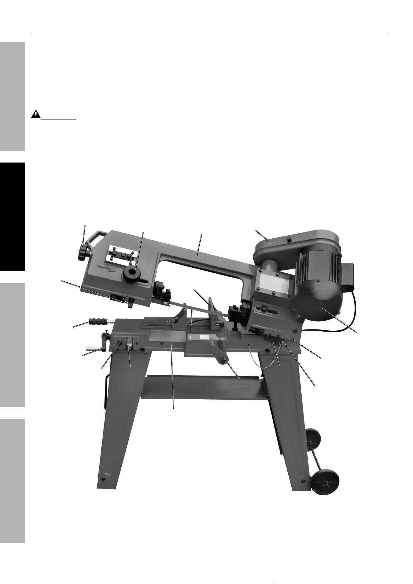
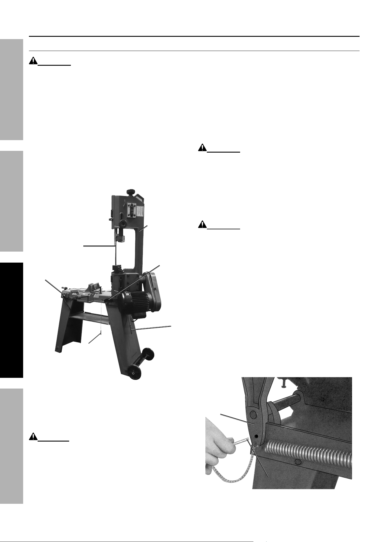
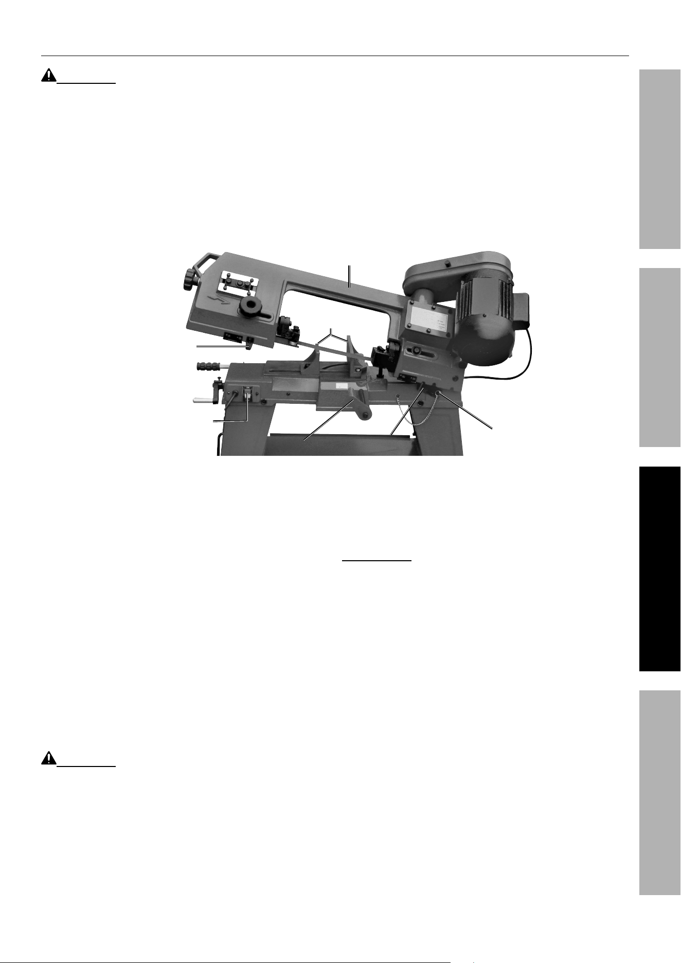
Functions
Switch Switch
Push-Off TipPush-Off Tip
MotorMotor
Pulley CoverPulley Cover
On/Off On/Off
SwitchSwitch
Stock StopStock Stop
Locking PinLocking Pin
Moveable Moveable
Vise PlateVise Plate
Power Power
CordCord
Hand Hand
WheelWheel
BladeBlade
Machine BedMachine Bed
Mitering Mitering
Vise PlateVise Plate
Guide Guide
Adjusting Adjusting
KnobKnob
Body FrameBody Frame
Blade Blade
Tension Tension
KnobKnob
Gear Gear
BoxBox
Feed Feed
HandleHandle
Support Support
PlatePlate
Locking Locking
NotchNotch
Page 13For technical questions, please call 1-888-866-5797.Item 93762
SAFETYOPERATIONMAINTENANCE SETUP
OPERATING INSTRUCTIONS
Read the ENTIRE IMPORTANT SAFETY INFORMATION section at the beginning of this
manual including all text under subheadings therein before set up or use of this product.
Tool Set Up
TO PREVENT SERIOUS INJURY FROM ACCIDENTAL OPERATION:
Turn the Power Switch of the tool off and unplug the tool from its electrical outlet
before performing any procedure in this section.
TO PREVENT SERIOUS INJURY:
DO NOT OPERATE WITH ANY GUARD DISABLED, DAMAGED, OR REMOVED.
Moving guards must move freely and close instantly.
To Use the Vise
1. Raise the Body Frame (62) to its vertical
position, and lock the Body Frame in place
with the Support Plate (154) and Locking
Pin (158) (see Figure I on page 11).
2. Open the Moveable Vise Plate (146) to
accept the workpiece by rotating the Hand
Wheel (180) counterclockwise (see Figure N).
3. Place the workpiece on the Machine Bed (147).
If the workpiece is long, support the end.
Moveable Vise Plate (146)Moveable Vise Plate (146)
Hand Wheel Hand Wheel
(180)(180)
Machine Bed (147)Machine Bed (147)
Mitering Vise Plate (143)Mitering Vise Plate (143)
Figure N
4. Clamp the workpiece firmly against the Mitering
Vise Plate (143) with the Moveable Vise Plate
by rotating the Hand Wheel clockwise.
To Use the Quick Vise Adjustment for an Angle Cut
1. Loosen the Bolt (138) and adjust the Mitering Vise
Plate to the desired angle as indicated by the Angle
Scale (170) (see Figure O). Re-tighten the Bolt.
2. Loosen the Bolt (144) and adjust the
Moveable Vise Plate to parallel the Mitering
Vise Plate. Re-tighten the Bolt.
Mitering Vise Mitering Vise
Plate (143)Plate (143)
Bolt (138)Bolt (138)
Moveable Vise Moveable Vise
Plate (146)Plate (146)
Bolt (144)Bolt (144)
Angle Scale (170)Angle Scale (170)
Figure O
Page 14 For technical questions, please call 1-888-866-5797. Item 93762
SAFETY OPERATION MAINTENANCESETUP
Adjustments
To Adjust the Stock Stop
1. Loosen the Socket Head Screw (161) that holds the
Stock Stop (162) to the Shaft (163) (see Figure P).
2. Adjust the Stock Stop to the desired length
position. Re-tighten the Socket Head Screw.
Shaft (163)
Shaft (163)
Socket Head
Socket Head
Screw (161)
Screw (161)
Stock Stop
Stock Stop
(162)
(162)
Figure P
To Adjust the Blade Guide Bearings
NOTE: Blade Guide Bearings (90, 94,
103, 107) adjustment is a critical factor in
the performance of the Band Saw.
NOTE: Before attempting to adjust the Blade Guide
Bearings, try installing a new Saw Blade (83) to correct
poor cutting. If a Saw Blade becomes dull on one side
sooner than the other, it will begin cutting crooked.
A Saw Blade replacement will correct this problem,
whereas Blade Guide Bearings adjustment will not.
Shaft (93)
Shaft (93)
Outer Blade
Outer Blade
Guide
Guide
Bearing
Bearing
(94)
(94)
Inner Blade
Inner Blade
Guide
Guide
Bearing (90)
Bearing (90)
Nut (88)
Nut (88)
Shaft
Shaft
(91)
(91)
Saw Blade (83)
Saw Blade (83)
Blade Guide
Blade Guide
Bracket Seat (84)
Bracket Seat (84)
Figure Q: Lower Blade Guide Assembly
1. If a new Saw Blade does not correct the
problem, check that the Blade Guide Bracket
Seats (84, 112) are clear of the Saw Blade.
2. There should be from 0.000" (just touching)
to 0.001" clearance between the Saw Blade
and Blade Guide Bearings (see Figure Q).
To obtain this clearance adjust as follows:
a. The Outer Blade Guide Bearings (94, 107) are
mounted to Shafts (93, 106) and can be adjusted.
b. Loosen the Nuts (88, 98) while holding the
Shafts (93, 106) with a Hex Key (not included).
c. Turn the Shafts (93, 106) until the Blade
Guide Bearings are appropriately clear of the
Blade. Then, re-tighten the Nuts (88, 98).
d. Adjust the Inner Blade Guide
Bearings (90, 103) in the same manner.
Page 15For technical questions, please call 1-888-866-5797.Item 93762
SAFETYOPERATIONMAINTENANCE SETUP
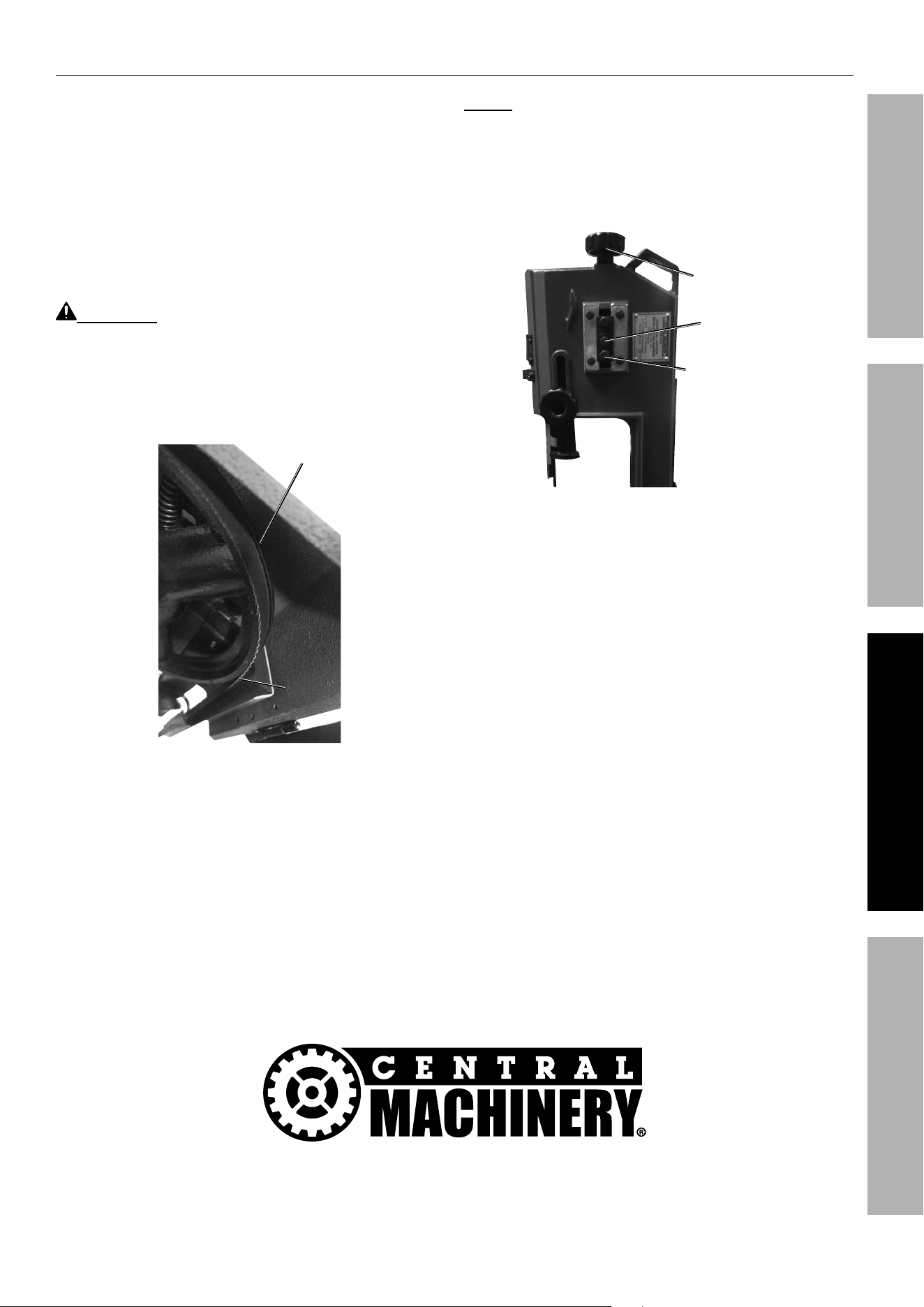
To Adjust the Blade Tracking
1. Remove the Locking Pin (116) from the Pivot (121).
2. Raise the Body Frame to its full vertical position.
Turn the Support Plate (154) to the right until
it firmly locks into the Body Frame (62) and
insert the Locking Pin (158) to lock Body Frame
into position (see Figure I on page 11).
3. Remove the Screw (113) and Flat Washer (114) to
open the Blade Back Cover (115). Turn on the Band
Saw and examine the Upper Blade Wheel (41).
WARNING! To avoid serious injury,
keep hands clear of turning blade.
4. The Saw Blade (83) is tracking properly when the
back of the Blade is just touching the edge of the
Upper Blade Wheel flange. The back of the Blade
should not rub against the flange (see Figure R).
Upper Blade Upper Blade
Wheel (41)Wheel (41)
Blade Blade
(83)(83)
Wheel FlangeWheel Flange
Figure R
NOTE: If adjustment is necessary, the Blade Guide
Bearings (90, 94, 103, 107) should be completely clear
of the Saw Blade (83) (see Figure Q on page 14).
5. Turn off the Band Saw and loosen the
middle Bolt (24) to a point where it is
loose but snug (see Figure S).
Bolt (24)Bolt (24)
Bolt (25)Bolt (25)
Blade TensionBlade Tension
Adjusting KnobAdjusting Knob
(37)(37)
Figure S
6. With the Band Saw running, turn the lower
Bolt (25) until the Saw Blade tracks properly.
Make sure Blade tension is maintained by
turning the Blade Tension Adjusting Knob (37).
7. When adjustment is complete, turn off the
Band Saw and re-tighten the middle Bolt.
8. Close the Blade Back Cover and secure
with the Screw and Flat Washer.
Page 16 For technical questions, please call 1-888-866-5797. Item 93762
SAFETY OPERATION MAINTENANCESETUP
To Adjust the Blade Tension
1. Raise the Body Frame (62) to its full vertical
position. Turn the Support Plate (154) to the
right until it firmly locks into the Body Frame and
insert the Locking Pin (158) to lock Body Frame
into position (see Figure I on page 11).
2. Turn the Blade Tension Adjusting
Knob (37) clockwise to increase
tension on the Saw Blade (83).
3. Turn the Blade Tension Adjusting
Knob counterclockwise to decrease
tension on the Saw Blade.
4. Correct tension has been acquired when the
Saw Blade is just tight enough for the Blade
Wheels (41, 57) to grip the Blade and turn it.
NOTE: Release blade tension when Band Saw
will not be used for extended periods.
To Adjust the Feed Rate
Adjust the feed rate of the Body Frame by
turning the Feed Handle (129) clockwise to
decrease the feed rate or counterclockwise
to increase the feed rate (see Figure T).
NOTICE: Do not turn the Feed Handle more
than one turn at a time. Excessive feed pressure
can break the Saw Blade. Insufficient feed
pressure dulls the Saw Blade rapidly.
Feed HandleFeed Handle
(129)(129)
Figure T
To Adjust the Blade Guide Brackets
1. The Upper Blade Guide Bracket (105) is adjustable
by loosening the Guide Adjusting Knob (49) and
sliding the Bracket up or down to accommodate
the depth of the workpiece (see Figure U).
2. The Blade Guide Brackets should be set as close
as possible to the workpiece, without interfering with
the workpiece or contacting the Machine Bed (147).
3. Once the adjustment is made,
re-tighten the Guide Adjusting Knob.
Blade Guide Blade Guide
BracketsBrackets
(92, 105)(92, 105)
Guide Adjusting Guide Adjusting
Knob (49)Knob (49)
Figure U

Page 17For technical questions, please call 1-888-866-5797.Item 93762
SAFETYOPERATIONMAINTENANCE SETUP
Workpiece and Work Area Set Up
1. Designate a work area that is clean and well-lit.
The work area must not allow access by children
or pets to prevent distraction and injury.
2. Route the power cord along a safe route to reach
the work area without creating a tripping hazard or
exposing the power cord to possible damage. The
power cord must reach the work area with enough
extra length to allow free movement while working.
3. Secure loose workpieces using a vise or clamps
(not included) to prevent movement while working.
4. There must not be objects, such as utility lines,
nearby that will present a hazard while working.
Page 18 For technical questions, please call 1-888-866-5797. Item 93762
SAFETY OPERATION MAINTENANCESETUP
General Operating Instructions
Vertical Position
WARNING! Always wear ANSI-approved safety
impact eye goggles when operating the Band Saw.
1. Do not plug the Power Cord into an
electrical outlet until all necessary
adjustments (as previously discussed
in this manual) have been made.
2. Remove the Locking Pin (116) from the Pivot (121).
3. Raise the Body Frame (62) to its full vertical
position, as described in ″To Convert the
Band Saw for Vertical Use″ on page 11.
4. Turn the Support Plate (154) clockwise
until it firmly locks into the Body Frame and
insert the Locking Pin (158) to lock Body
Frame in position (see Figure V).
Saw Blade (83)Saw Blade (83)
Power Switch (169)Power Switch (169)
Body Body
Frame (62)Frame (62)
Support Support
Plate (154)Plate (154)
Locking Locking
Pin (158)Pin (158)
Locking Locking
Pin (116)Pin (116)
Figure V
5. Once all necessary adjustments to the Band Saw
have been made, plug the Power Cord2 (168) into
the nearest 120 volt, grounded, electrical outlet.
6. Turn the Power Switch (169) to its “ON” position.
CAUTION! Cut only flat workpieces when
the Band Saw is in its vertical position. Never
attempt to cut pipes or other round objects
with the Band Saw in its vertical position.
7. Before cutting, turn on the Band Saw and check
for excessively loose Saw Blade (83) tension
or machine vibration. Turn off the Band Saw
and correct any problems before using.
8. Set the workpiece on the Vertical Cutting
Table (197). Keep downward pressure on the
workpiece throughout the cutting process.
9. When cutting a large workpiece, make sure its entire
length is properly supported. If necessary, use a
roller stand (not included) with a larger workpiece.
10. Allow the Saw Blade to reach full speed before
feeding the workpiece into the Saw Blade.
WARNING! TO PREVENT SERIOUS
INJURY: Keep hands and fingers safely
away from the cutting area.
11. Feed the workpiece into the Saw Blade
gradually. Do not force the Band Saw to remove
material faster than it is designed to cut.
12. Use two hands and hold workpiece
securely against table at all times.
WARNING! Never attempt to remove material
stuck in the moving parts of the Band Saw while it is
plugged in and running. Turn off the Band Saw if the
workpiece is to be backed out of an uncompleted cut.
13. Once the cut is made, turn the Power
Switch (169) to its “OFF” position and unplug
the Power Cord from its electrical outlet.
14. Wait until the Saw Blade comes to a complete
stop. Then, remove the workpiece and scrap
material from the Vertical Cutting Table.
15. Remove the Locking Pin and turn the
Support Plate to the left. Then, lower the
Body Frame to its horizontal position.
16. Clean, lock in the horizontal position by
inserting the Locking Pin (116) into the
Pivot (121) (see Figure W), then store the
tool indoors out of children’s reach.
Pivot (121)Pivot (121)
Locking Locking
Pin (116)Pin (116)
Figure W
Page 19For technical questions, please call 1-888-866-5797.Item 93762
SAFETYOPERATIONMAINTENANCE SETUP
Horizontal Position
WARNING! Always wear ANSI-approved safety
impact eye goggles when operating the Band Saw.
1. Do not plug the Power Cord into an
electrical outlet until all necessary
adjustments (as previously discussed
in this manual) have been made.
2. If needed, convert the Band Saw for horizontal
use as described in ″To Convert the Band
Saw for Horizontal Use″ on page 12.
3. Remove the Locking Pin (116) from the Pivot (121).
4. Raise the Body Frame (62) to its full vertical
position. Turn the Support Plate (154) clockwise
until it firmly locks into the Body Frame and insert
the Locking Pin (158) to lock the Body Frame
in position (see Figure W on page 18).
5. Secure the workpiece in the Vise
assembly (143, 146). When cutting a large
workpiece, make sure its entire length is properly
supported. If necessary, use a roller stand (not
included) with a larger workpiece (see Figure X).
Vise Assy.Vise Assy.
(143, 146)(143, 146)
Stock Stop (162)Stock Stop (162)
Body Frame (62)Body Frame (62)
Support PlateSupport Plate
(154)(154)
Power Power
SwitchSwitch
(169)(169)
Switch Push-Switch Push-
Off Tip (45)Off Tip (45)
Locking PinLocking Pin
(158)(158)
Figure X
6. If cutting several workpieces at the same
length, you may wish to adjust the Stock
Stop (162) to the desired position.
7. Once all necessary adjustments to the Band Saw
have been made, plug the Power Cord into the
nearest 120 volt, grounded, electrical outlet.
8. Before cutting, turn on the Band Saw and
check for excessively loose Saw Blade tension
or machine vibration. Turn off the Band Saw
and correct any problems before using.
9. To begin cutting, turn the Power Switch (169)
to its “ON” position. Remove the Locking Pin
and slowly lower the Body Frame until the Saw
Blade (83) is just above the workpiece cut line.
10. Allow the Saw Blade to reach full speed before
feeding the Saw Blade into the workpiece.
WARNING! TO PREVENT SERIOUS
INJURY: Keep hands and fingers safely
away from the cutting area.
11. Slowly lower the Body Frame, while it gradually
feeds the Saw Blade into the workpiece. Do
not force the Band Saw to remove material
faster than it is designed to cut.
12. Never attempt to remove material stuck in the
moving parts of the Band Saw while it is plugged in
and running. Turn off the Band Saw if the workpiece
is to be backed out of an uncompleted cut.
IMPORTANT: When in the horizontal cutting mode
only, the Switch Push-Off Tip (45) will automatically turn
the Power Switch to its “OFF” position and shut off the
Band Saw Motor when the cut has been completed.
13. Once the cut is made, check to make sure the
Power Switch is in its “OFF” position and unplug
the Power Cord from its electrical outlet.
14. Wait until the Saw Blade comes to a complete
stop. Raise the Body Frame to its full vertical
position. Turn the Support Plate clockwise until
it firmly locks into the Body Frame and insert
the Locking Pin (158) to lock Body Frame in
position. Remove the workpiece from the Vise
assembly and scrap material from the Machine
Bed (147) of the Band Saw. Then, slowly lower
the Body Frame to its horizontal position.
15. Clean, lock in the horizontal position by
inserting the Locking Pin into the Pivot (see
Figure W on page 18), then store the
tool indoors out of children’s reach.
Page 20 For technical questions, please call 1-888-866-5797. Item 93762
SAFETY OPERATION MAINTENANCESETUP
MAINTENANCE AND SERVICING
Procedures not specifically explained in this manual must
be performed only by a qualified technician.
TO PREVENT SERIOUS INJURY FROM ACCIDENTAL OPERATION:
Turn the Power Switch of the tool off and unplug the tool from its electrical outlet
before performing any procedure in this section.
TO PREVENT SERIOUS INJURY FROM TOOL FAILURE:
Do not use damaged equipment. If abnormal noise or vibration
occurs, have the problem corrected before further use.
Cleaning, Maintenance, and Lubrication
1. BEFORE EACH USE, inspect the general
condition of the tool. Check for:
• loose hardware,
• misalignment or binding of moving parts,
• cracked or broken parts,
• damaged electrical wiring, and
• any other condition that may
affect its safe operation.
2. BEFORE EACH USE, inspect the Saw
Blade (83). Using a dull Saw Blade will cause
excessive wear on the Motor of the Band Saw
and will not produce a satisfactory cut. Replace
with a new Saw Blade when needed.
3. AFTER USE, wipe external surfaces of the tool
with clean cloth. To clean the exterior parts
of the Band Saw, use only a clean cloth and
mild detergent or mild solvent to clean the body
of the Saw. Do not immerse any electrical
part of the machine in any liquids.
4. Periodically, wear ANSI-approved
safety goggles and NIOSH-approved
breathing protection and blow dust out of
the motor vents using dry compressed air.
5. When the Band Saw is not in use or when
transporting the tool: Always lower the Body
Frame (62) to its horizontal position and insert the
Locking Pin (116) into the Pivot (121) to secure
the Body Frame in place (see Figure Y).
Pivot (121)Pivot (121)
Locking Locking
Pin (116)Pin (116)
Figure Y
WARNING! All maintenance, service, or
repairs not mentioned in this manual must only
be performed by a qualified service technician.
WARNING! If the supply cord of this
power tool is damaged, it must be replaced
only by a qualified service technician.
Replacing the Saw Blade
1. Wear heavy-duty work gloves to avoid
accidental cuts from the Saw Blade
when performing this procedure.
2. Raise the Body Frame (62) to its full vertical position.
Turn the Support Plate (154) clockwise until it firmly
locks into the Body Frame and insert the Locking
Pin (158) to lock the Body Frame in position.
3. Release Saw Blade tension by turning the Blade
Tension Adjusting Knob (37). (See Figure Z)
4. Remove the Screw (113) and Flat Washer (114)
to open the Blade Back Cover (115) and
access the Saw Blade (see Figure Z).
Page 21For technical questions, please call 1-888-866-5797.Item 93762
SAFETYOPERATIONMAINTENANCE SETUP
Screw Screw
(113)(113)
Flat Flat
Washer Washer
(114)(114)
Upper Blade Upper Blade
Wheel (41)Wheel (41)
Lower Blade Lower Blade
Wheel (57)Wheel (57)
SawSaw
BladeBlade
(83)(83)
Blade Blade
Back Back
Cover Cover
(115)(115)
Blade Tension Blade Tension
Adjusting Knob (37)Adjusting Knob (37)
Upper Upper
Guide Guide
Ass′y.Ass′y.
Lower Lower
Guide Guide
Ass′y.Ass′y.
BLADE BLADE
TEETH POINT TEETH POINT
DOWNWARDDOWNWARD
Figure Z
5. Slip the old Saw Blade off the Upper
Blade Wheel (41), Lower Blade
Wheel (57), and Guide assemblies.
6. Place the new Saw Blade between each of the
Guide assemblies and around the Upper Blade
Wheel and Lower Blade Wheel.
IMPORTANT: The teeth must be pointing
downward toward the Motor.
NOTE: The Band Saw is equipped with a 64-1/2″
diameter, 0.025″ thick, 1/2″ wide, 14 teeth per inch
Saw Blade. The machine will also accept Blades in
4, 6, 8, and 10 tooth sizes. The choice of Blade pitch
is determined by the thickness of the material to be
cut. The thinner the workpiece, the greater the number
of teeth required for proper cutting. A minimum of
3 teeth should engage the workpiece at all times.
CAUTION! If the teeth of the Saw Blade are so far
apart that they straddle the workpiece, severe damage
to the workpiece and/or Saw Blade will result.
7. Tighten the tension on the new Saw Blade by
turning the Blade Tension Adjusting Knob.
8. Close the Blade Back Cover. and secure
with the Screw and Flat Washer.
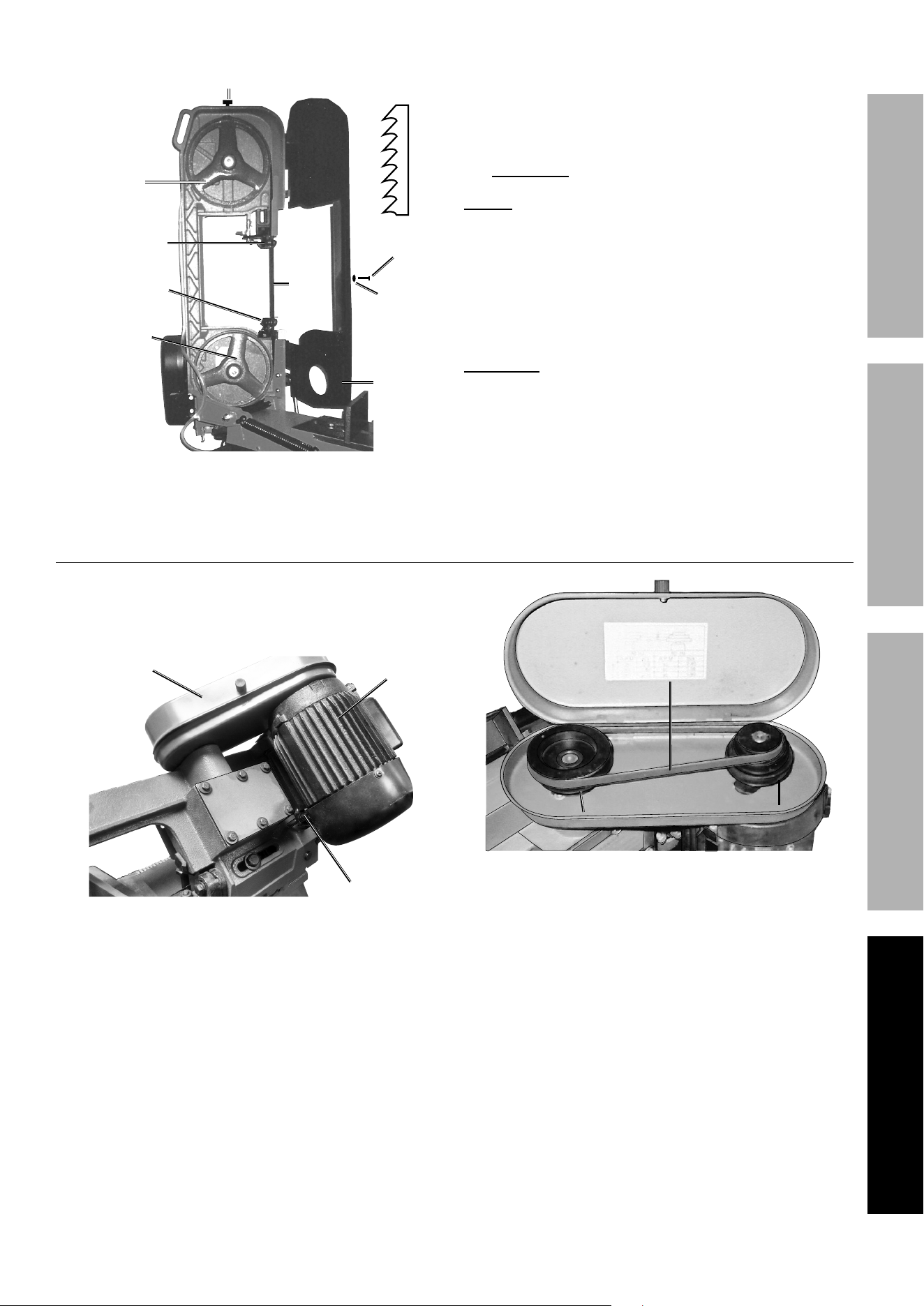
Replacing the V-Belt
1. The Band Saw uses a size 0-506
V-Belt (13). To replace the V-Belt:
a. Open the Pulley Cover (75) (see Figure AA).
BoltBolt
(70)(70)
Motor (82)Motor (82)
Pulley Pulley
Cover (75)Cover (75)
Figure AA
b. Loosen the Bolts (70, 74) and press
the Motor (82) toward the Body to
release tension on the old V-Belt.
c. Remove the old V-Belt from the two
Pulleys (1, 80) (see Figure AB).
Motor Pulley (80)Motor Pulley (80)
Spindle Pulley (1)Spindle Pulley (1)
V-Belt (13)V-Belt (13)
Figure AB
d. Place the new V-Belt onto the proper
Pulley combination for the desired Blade
speed (see Figure H on page 10).
e. Adjust the position of the Motor (82) to obtain
approximately 1/2" depression in the V-Belt
when applying pressure with your thumb.
f. Tighten the Bolts to secure the Motor in place.
Page 22 For technical questions, please call 1-888-866-5797. Item 93762
SAFETY OPERATION MAINTENANCESETUP
Lubricating the Worm Gear and Worm Shaft
The Worm Shaft (12) and Worm Gear (20)
run in an oil bath Gear Box and should not require
an oil change more than once a year, unless
the oil becomes contaminated or a leak occurs
due to improper replacement of the Gear Box
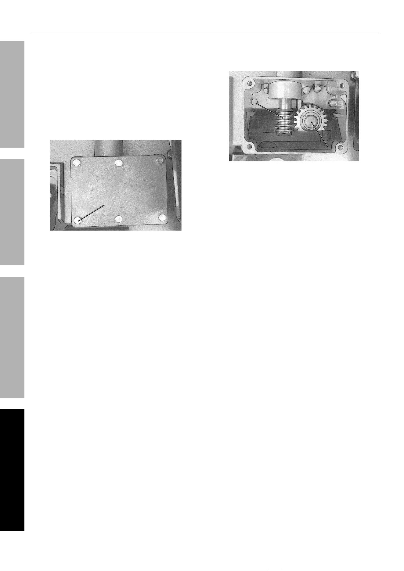
Cover (17). To change oil in the Gear Box:
1. Position the Body Frame (62) in the horizontal
position (see Figure V on page 18).
2. Remove the six Bolts (14), Gear Box Cover (17),
and Gear Box Gasket (18) (see Figure AC).
Gear Box Gear Box
Cover (17)Cover (17)
Bolt (14)Bolt (14)
Figure AC
3. Remove the old oil from inside the Gear Box
and replace the oil using 140 weight gear oil.
The new oil should just come to the edge of the
Gear Box. Do not overfill (see Figure AD).
Worm Worm
Shaft (12)Shaft (12)
Worm Worm
Gear (20)Gear (20)
Figure AD
4. Replace the Gear Box Gasket, Gear
Box Cover, and six Bolts.

Page 23For technical questions, please call 1-888-866-5797.Item 93762
SAFETYOPERATIONMAINTENANCE SETUP
Troubleshooting
Problem Possible Causes Likely Solutions
Tool will not start. 1. Cord not connected.
2. No power at outlet.
3. Tool’s thermal reset breaker
tripped (if equipped).
4. Internal damage or wear. (Carbon
brushes or switch, for example.)
1. Check that cord is plugged in.
2. Check power at outlet. If outlet is unpowered,
turn off tool and check circuit breaker.
If breaker is tripped, make sure circuit is right
capacity for tool and circuit has no other loads.
3. Turn off tool and allow to cool.
Press reset button on tool.
4. Have technician service tool.
Tool operates
slowly.
Extension cord too long or
wire size too small.
Eliminate use of extension cord. If an extension cord
is needed, use one with the proper diameter for its
length and load. See Table A on page 3.
Performance
decreases
over time.
1. Saw Blade dull or damaged.
2. Carbon brushes worn or damaged.
1. Replace Saw Blade.
2. Have qualified technician replace brushes.
Excessive noise
or rattling.
Internal damage or wear. (Carbon
brushes or bearings, for example.)
Have technician service tool.
Overheating. 1. Forcing machine to work too fast.
2. Saw Blade dull or damaged.
3. Blocked motor housing vents.
4. Motor being strained by long or
small diameter extension cord.
5. Saw Blade tension is too high.
6. V-Belt tension too high.
7. Blade is too coarse or too fine for
workpiece.
8. Gear not aligned properly.
9. Gears need lubrication.
1. Allow machine to work at its own rate.
2. Replace Saw Blade.
3. Wear ANSI-approved safety goggles and
NIOSH-approved dust mask/respirator while
blowing dust out of motor using compressed air.
4. Eliminate use of extension cord.
If an extension cord is needed, use one with
the proper diameter for its length and load.
See Table A on page 3.
5. Gradually adjust Saw Blade tension until optimal
tension has been achieved. See page 16.
6. Gradually adjust V-Belt tension until optimal
tension has been achieved. See page 10.
7. See ″Replacing the Saw Blade″ on page
20 for recommended Blade type. Replace
with more appropriate Saw Blade.
8. Adjust Gears so that Worm is in center of Gear.
9. Check Oil Bath. See page 22.
Excessive Blade
breakage.
1. Saw Blade is loose.
2. Saw Blade turns too
quickly or too slowly.
3. Vise is not gripping the workpiece.
4. Wheel Flange is eroding Saw Blade.
5. Saw Blade teeth are spaced too
widely for the workpiece material.
6. Saw Blade is not permitted
to reach full speed before
workpiece is fed into it.
7. Guides are poorly aligned.
1. Tighten Blade tension.
2. Check manual for correct Blade
speed. See page 10.
3. Clamp workpiece securely.
4. Adjust Wheel alignment. See page 15.
5. See ″Replacing the Saw Blade″ on page
20 for recommended Blade type. Replace
with more appropriate Saw Blade.
6. Allow Blade to reach full speed before feeding
material into it.
7. Adjust guides.
Follow all safety precautions whenever diagnosing or servicing the tool.
Disconnect power supply before service.

Page 24 For technical questions, please call 1-888-866-5797. Item 93762
SAFETY OPERATION MAINTENANCESETUP
Problem Possible Causes Likely Solutions
Premature
Blade dulling
1. Saw Blade teeth are spaced too
widely for the workpiece material.
2. Saw Blade turns too quickly.
3. Body Frame descends too lightly.
4. Saw Blade installed backwards.
5. Insufficient Saw Blade tension.
1. Check manual for recommended Blade type. See
page 20 and replace with appropriate Saw Blade.
2. Try next lower speed. See page 10.
3. Increase pressure by reducing spring
tension on side of Saw. See page 16.
4. Re-install Saw Blade properly.
5. Gradually increase Saw Blade tension until optimal
tension has been achieved. See page 16.
Blade cuts
crooked.
1. Vise is not square with Saw Blade.
2. Feed pressure is too great.
3. Guide Bearing is not adjusted
properly.
4. Insufficient Saw Blade tension.
5. Blade Guides are too far
from workpiece.
6. Saw Blade is dull.
7. Saw Blade turns too quickly
or too slowly for workpiece.
8. Saw Blade tracks too far away
from Wheel Flanges.
1. Adjust Vise so it is square with Blade.
Always clamp work tightly in Vise.
2. Reduce pressure by increasing spring
tension on side of Saw. See page 16.
3. Adjust Guide Bearing to 0.001" greater
than maximum thickness, including the
weld of the Saw. See page 14.
4. Gradually increase Saw Blade tension until optimal
tension has been achieved. See page 16.
5. Move Blade Guide as close to
workpiece as possible.
6. Replace Saw Blade. See page 20.
7. Check Manual for recommended
speeds. See page 10.
8. Adjust Saw Blade tracking. See page 15.
Blade cuts
rough.
1. Saw Blade turns too quickly.
2. Feed pressure is too heavy.
3. Saw Blade teeth are spaced too
widely for the workpiece material.
1. See page 10 for recommended speeds.
2. Reduce pressure by increasing spring
tension on side of Saw. See page 16.
3. Check manual for recommended Blade
type. See page 20 and replace with
more appropriate Saw Blade.
Blade twists. 1. Saw Blade is caught in
the workpiece cut.
2. Saw Blade tension is too high.
1. Reduce pressure by increasing spring
tension on side of Saw. See page 16.
2. Gradually adjust Saw Blade tension until optimal
tension has been achieved. See page 16.
Unusual wear
on side/back
of Blade.
1. Blade Guides are worn down.
2. Blade Guide Bearings
are out of place.
3. Blade Guide Bearing
Bracket is loose.
1. Replace Blade Guides. See page 16.
2. Adjust Blade Guide Bearings. See page 14.
3. Tighten Blade Guide Bearing Bracket.
Follow all safety precautions whenever diagnosing or servicing the tool.
Disconnect power supply before service.

Page 25For technical questions, please call 1-888-866-5797.Item 93762
SAFETYOPERATIONMAINTENANCE SETUP
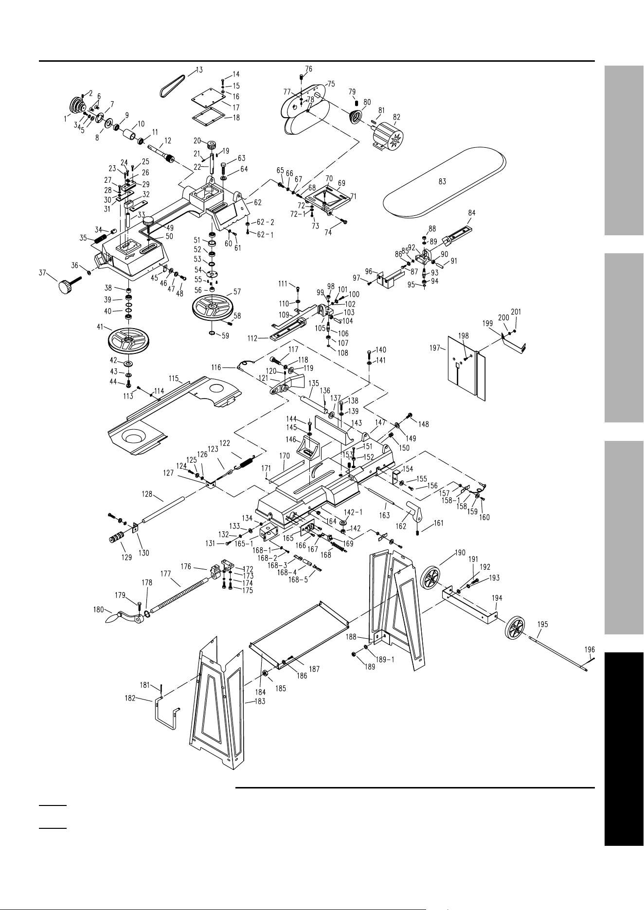
Part Description Qty
1 Spindle Pulley 1
2 Socket Head Screw (M8x8) 1
3 Screw (M4x8) 1
4 Flat Washer (4) 1
5 Flat Washer (5) 1
6 Screw (M4x8) 2
7 Seal Cover 1
8 Oil Seal (B15x35x7) 1
9 Bearing (6202Z) 1
10 Spacer 1
11 Bearing (6202Z) 1
12 Worm Shaft 1
13 V-Belt 1
14 Bolt (M6x16) 6
15 Spring Washer (6) 6
16 Flat Washer (6) 6
17 Gear Box Cover 1
18 Gear Box Gasket 1
19 Key (C5x28) 2
20 Worm Gear 1
21 Pin (5x26) 1
22 Gear Shaft 1
23 Bolt (M8x30) 1
24 Bolt (M8x16) 1
25 Bolt (M8x30) 1
26 Flat Washer 1
27 Bolt (M6x12) 4
28 Spring Washer (6) 4
29 Blade Tension Sliding Plate 1
30 Flat Washer (6) 4
31 Blade Tension Sliding Guide 2
32 Sliding Plate Draw Block 1
33 Blade Wheel Shaft 1
34 Nut 1
35 Spring 1
36 Flat Washer 1
37 Blade Tension Adjusting Knob 1
38 Spacer 1
39 Bearing (6202Z) 2
40 Spacer 2
41 Upper Blade Wheel 1
42 Washer 1
43 Flat Washer (5) 1
44 Socket Head Screw (M5x15) 1
45 Switch Push-Off Tip 1
Part Description Qty
46 Flat Washer (6) 1
47 Spring Washer (6) 1
48 Screw (M6x14) 1
49 Guide Adjusting Knob 1
50 Flat Washer 1
51 Spacer 1
52 Bearing (6202Z) 2
53 Oil Seal (B15x35x7) 1
54 Seal Cover 1
55 Screw (M4x8) 3
56 Spacer 1
57 Lower Blade Wheel 1
58 Socket Head Screw (M8x8) 1
59 Ring (15) 1
60 Flat Washer (4) 4
61 Screw (M4x6) 4
62 Body Frame 1
62-1 Bolt (M6x25) 1
62-2 Nut 1
63 Bolt (M10x30) 1
64 Flat Washer 1
65 Screw (M6x10) 1
66 Spring Washer (6) 1
67 Flat Washer (6) 1
68 Bolt (M12x30) 1
69 Motor Plate 1
70 Bolt (M8x55) 1
71 Nut 1
72 Flat Washer (8) 4
72-1 Spring Washer (8) 4
73 Bolt (M8x20) 4
74 Bolt (M12x35) 1
75 Pulley Cover 1
76 Knob 1
77 Flat Washer (4) 1
78 Screw (M4x8) 1
79 Socket Head Screw (M8x8) 1
80 Motor Pulley 1
81 Shaft Key (C5x28) 1
82 Motor 1
83 Saw Blade 1
84 Lower Blade Guide Bracket Seat 1
85 Flat Washer (16) 1
86 Spring Washer (8) 1
87 Bolt (M8x30) 1
PARTS LIST AND DIAGRAM
PLEASE READ THE FOLLOWING CAREFULLY
THE MANUFACTURER AND/OR DISTRIBUTOR HAS PROVIDED THE PARTS LIST AND ASSEMBLY DIAGRAM
IN THIS MANUAL AS A REFERENCE TOOL ONLY. NEITHER THE MANUFACTURER OR DISTRIBUTOR
MAKES ANY REPRESENTATION OR WARRANTY OF ANY KIND TO THE BUYER THAT HE OR SHE IS
QUALIFIED TO MAKE ANY REPAIRS TO THE PRODUCT, OR THAT HE OR SHE IS QUALIFIED TO REPLACE
ANY PARTS OF THE PRODUCT. IN FACT, THE MANUFACTURER AND/OR DISTRIBUTOR EXPRESSLY
STATES THAT ALL REPAIRS AND PARTS REPLACEMENTS SHOULD BE UNDERTAKEN BY CERTIFIED AND
LICENSED TECHNICIANS, AND NOT BY THE BUYER. THE BUYER ASSUMES ALL RISK AND LIABILITY
ARISING OUT OF HIS OR HER REPAIRS TO THE ORIGINAL PRODUCT OR REPLACEMENT PARTS
THERETO, OR ARISING OUT OF HIS OR HER INSTALLATION OF REPLACEMENT PARTS THERETO.
Parts List

Page 26 For technical questions, please call 1-888-866-5797. Item 93762
SAFETY OPERATION MAINTENANCESETUP
Part Description Qty
88 (Lower) Nut 2
89 Spring Washer (8) 2
90 Inner Lower Blade Guide
Bearing (180029)
1
91 Pin 1
92 Lower Blade Guide Bracket 1
93 Lower Shaft 2
94 Outer Lower Blade Guide
Bearing (180029)
2
95 Ring (9) 2
96 Horizontal Cutting Guard 1
97 Screw (M6x16) 2
98 (Upper) Nut 2
99 Spring Washer (8) 2
100 Bolt (M8x30) 1
101 Spring Washer (8) 1
102 Flat Washer 1
103 Inner Upper Blade Guide
Bearing (180029)
1
104 Pin 1
105 Upper Blade Guide Bracket 1
106 Upper Shaft 2
107 Outer Upper Blade Guide
Bearing (180029)
2
108 Ring (9) 2
109 Blade Guard 1
110 Flat Washer (4) 2
111 Screw (M4x6) 2
112 Upper Blade Guide Bracket Seat 1
113 Screw (M6x10) 1
114 Flat Washer (6) 1
115 Blade Back Cover 1
116 Locking Pin 1
117 Socket Head Screw (M10x35) 2
118 Spring Washer (10) 2
119 Flat Washer 2
120 Socket Head Screw (M8x8) 1
121 Pivot 1
122 Spring 1
123 Spring Adjusting Screw 1
124 Bolt (M6x12) 2
125 Spring Washer (6) 2
126 Flat Washer (6) 2
127 Support 1
128 Adjusting Rod 1
129 Feed Handle 1
130 Support 1
131 Bolt (M8x20) 6
132 Spring Washer (8) 6
133 Flat Washer (8) 6
134 Nut 6
135 Pivot Rod 1
136 Pin (4x25) 1
137 Flat Washer (16) 1
138 Bolt 1
140 Bolt (M8x40) 1
141 Flat Washer (8) 1
142 Nut 1
142-1 Flat Washer 1
143 Mitering Vise Plate 1
144 Bolt (M10x25) 1
145 Flat Washer 1
146 Moveable Vise Plate 1
Part Description Qty
147 Machine Bed 1
148 Screw (M5x8) 2
149 Flat Washer (5) 2
150 Grommet 1
151 Bolt (M12x70) 1
152 Nut 1
153 Set Screw (M8x15) 1
154 Support Plate 1
155 Flat Washer (8) 1
156 Bolt (M8x16) 1
157 Nut 2
158 Locking Pin 1
158-1 Button 2
159 Flat Washer (5) 2
160 Screw (M5x18) 2
161 Socket Head Screw (M8x8) 1
162 Stock Stop 1
163 Shaft 1
164 Cable Protector 1
165 Switch Panel 1
165-1 Switch Box 1
166 Screw (M3.9x30) 2
167 Power Cord Grommet 2
168 Power Cord 1
168-1 Serrated Washer (5) 2
168-2 Bolt 2
168-3 Terminal 2
168-4 Insulation Sleeve 4
168-5 Metal Plate 4
169 Power Switch 1
170 Angle Scale 1
171 Rivet 2
172 Lead Screw Support 1
173 Flat Washer (6) 2
174 Spring Washer (6) 2
175 Bolt (M6x18) 2
176 Nut 1
177 Lead Screw 1
178 Spacer 1
178-1 Socket Head Screw (M6x6) 1
179 Bolt (M6x12) 1
180 Hand Wheel 1
181 Pin (2.5) 2
182 Pull Handle 1
183 Stand 2
184 Tool Plate 1
185 Nut 4
186 Flat Washer (6) 4
187 Screw (M6x12) 4
188 Stand Support 4
189 Nut 8
189-1 Flat Washer (6) 8
190 Wheel 2
191 Bolt (M6x12) 8
192 Flat Washer (6) 8
193 Spring Washer (6) 8
194 Wheel Bracket 1
195 Wheel Shaft 1
196 Pin (2.5) 4
197 Vertical Cutting Table 1
198 Screw (M6x16) 1
199 Vertical Cutting Table Support 1
200 Flat Washer 1
201 Nut 1
Page 27For technical questions, please call 1-888-866-5797.Item 93762
SAFETYOPERATIONMAINTENANCE SETUP
Assembly Diagram
Record Product’s Serial Number Here:
Note: If product has no serial number, record month and year of purchase instead.
Note: Some parts are listed and shown for illustration purposes only, and are not available
individually as replacement parts. Specify UPC 792363937627 when ordering parts.

LIMITED 90 DAY WARRANTY
Harbor Freight Tools Co. makes every effort to assure that its products meet high quality and durability
standards, and warrants to the original purchaser that this product is free from defects in materials and workmanship
for the period of 90 days from the date of purchase. This warranty does not apply to damage due directly or
indirectly, to misuse, abuse, negligence or accidents, repairs or alterations outside our facilities, criminal activity,
improper installation, normal wear and tear, or to lack of maintenance. We shall in no event be liable for death,
injuries to persons or property, or for incidental, contingent, special or consequential damages arising from the use
of our product. Some states do not allow the exclusion or limitation of incidental or consequential damages, so the
above limitation of exclusion may not apply to you. THIS WARRANTY IS EXPRESSLY IN LIEU OF ALL OTHER
WARRANTIES, EXPRESS OR IMPLIED, INCLUDING THE WARRANTIES OF MERCHANTABILITY AND FITNESS.
To take advantage of this warranty, the product or part must be returned to us with transportation charges
prepaid. Proof of purchase date and an explanation of the complaint must accompany the merchandise.
If our inspection verifies the defect, we will either repair or replace the product at our election or we may
elect to refund the purchase price if we cannot readily and quickly provide you with a replacement. We will
return repaired products at our expense, but if we determine there is no defect, or that the defect resulted
from causes not within the scope of our warranty, then you must bear the cost of returning the product.
This warranty gives you specific legal rights and you may also have other rights which vary from state to state.
26541 Agoura Road • Calabasas, CA 91302 • 1-888-866-5797