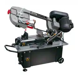
7" x 12"
METAL CUTTING
BAND SAW
Model # 39707
Your new tool has been engineered and manufactured to WEN’s highest standards for dependability, ease
of operation, and operator safety. When properly cared for, this product will supply you years of rugged,
trouble-free performance. Pay close attention to the rules for safe operation, warnings, and cautions. If
you use your tool properly and for its intended purpose, you will enjoy years of safe, reliable service.
IMPORTANT:
NEED HELP? CONTACT US!
Have product questions? Need technical support?
Please feel free to contact us at:
800-232-1195
WENPRODUCTS.COM
(M-F 8AM-5PM CST)
bit.ly/wenvideo
For replacement parts visit
WENPRODUCTS.COM
NOTICE: Please refer to wenproducts.com for the most up-to-date instruction manual.
4000909

PRODUCT SPECIFICATIONS
39707
120V, 60 Hz, 9.5A, Single Phase, Class B
1700 RPM
135, 160, 230, 390 FPM
93 x 3/4 x 0.032 in. (2360 x 19 x 0.9 mm)
0° to 45°
7 in. (180 mm)
7 x 12 in. (180 x 305 mm)
3-15/16 in. (100 mm)
4-1/3 x 6-1/4 in. (110 x 170 mm)
L-CKE 150# gear oil
5 to 6.7 fl. oz. (150 to 200 ml)
75 dB
48 x 20-3/4 x 39-1/2 in.
319.7 lbs
TABLE OF CONTENTS
2
3
4
6
7
8
9
11
15
17
22
27
Product Specifications
Safety Introduction
General Safety Rules
Specific Rules for Metal Band Saws
Electrical Information
Know Your Metal Band Saw
Assembly
Preparation & Adjustments
Operation
Maintenance
Exploded View & Parts List
Warranty Statement
Model Number:
Motor:
Motor Speed:
Blade Speed:
Blade Size:
Beveling Vise Angle:
Round Cutting Capacity @ 90° :
Rectangular Cutting Capcity @ 90° :
Round Cutting Capacity @ 45° :
Rectangular Cutting Capcity @ 45° :
Gear Box Oil Type:
Gear Box Oil Capacity:
Noise Level:
Product Dimensions:
Product Weight:
2
SAFETY INTRODUCTION
Thanks for purchasing the WEN Metal Band Saw. This is an exciting moment. You have received your new tool,
opened the box, and are now about to read through the instruction manual. This manual provides information
regarding potential safety concerns, as well as helpful assembly and operating instructions. Safe operation of this
tool requires that you read and understand this operator’s manual and all labels affixed to the tool.
SAFETY ALERT SYMBOL: Indicates danger, warning, or caution. The safety symbols and the
explanations with them deserve your careful attention and understanding. Always follow the safety
precautions to reduce the risk of fire, electric shock and personal injury. However, please note that
these instructions and warnings are not substitutes for proper accident prevention measures.
NOTE: The following safety information is not meant to cover all possible conditions and situations that may oc-
cur. WEN reserves the right to change this product and specifications at any time without prior notice.
Keep this manual available to all users during the entire life of the tool and review it frequently
to maximize safety for both yourself and others.
3

GENERAL SAFETY RULES
WARNING! Read all safety warnings and instructions. Failure to follow all instructions may result
in electric shock, fire and serious injury. The term “power tool” in the warnings refers to your mains-
operated (corded) power tool. Save all warnings and instructions for future reference.
WORK AREA SAFETY
1. Keep work area clean and well lit. Cluttered or dark areas invite accidents.
2. Do not operate power tools in explosive atmospheres, such as in the presence of flammable liquids, gases or
dust. Power tools create sparks which may ignite the dust or fumes.
3. Keep children and bystanders away while operating a power tool. Distractions can cause you to lose control.
ELECTRICAL SAFETY
1. Power tool plugs must match the outlet. Never modify the plug in any way. Do not use any adapter plugs with
earthed (grounded) power tools. Unmodified plugs and matching outlets will reduce risk of electric shock.
2. Avoid body contact with earthed or grounded surfaces such as pipes, radiators, ranges and refrigerators. There
is an increased risk of electric shock if your body is earthed or grounded.
3. Do not expose power tools to rain or wet conditions. Water entering a power tool will increase the risk of elec-
tric shock.
4. Do not abuse the cord. Never use the cord for carrying, pulling or unplugging the power tool. Keep cord away
from heat, oil, sharp edges or moving parts. Damaged or entangled cords increase the risk of electric shock.
5. When operating a power tool outdoors, use an extension cord suitable for outdoor use. Use of a cord suitable
for outdoor use reduces the risk of electric shock.
6. If operating a power tool in a damp location is unavoidable, use a ground fault circuit interrupter (GFCI) pro-
tected supply. Use of a GFCI reduces the risk of electric shock.
PERSONAL SAFETY
1. Stay alert, watch what you are doing and use common sense when operating a power tool. Do not use a power
tool while you are tired or under the influence of drugs, alcohol or medication. A moment of inattention while
operating power tools may result in serious personal injury.
2. Use personal protective equipment. Always wear eye protection. Protective equipment such as dust mask, non-
skid safety shoes, hard hat, or hearing protection used for appropriate conditions will reduce personal injuries.
3. Prevent unintentional starting. Ensure the switch is in the off-position before connecting to power source and/
or battery pack, picking up or carrying the tool. Carrying power tools with your finger on the switch or energizing
power tools that have the switch on invites accidents.
4. Remove any adjusting key or wrench before turning the power tool on. A wrench or a key left attached to a
rotating part of the power tool may result in personal injury.
4

GENERAL SAFETY RULES
5. Do not overreach. Keep proper footing and balance at all times. This enables better control of the power tool
in unexpected situations.
6. Dress properly. Do not wear loose clothing or jewelry. Keep your hair, clothing and gloves away from moving
parts. Loose clothes, jewelry or long hair can be caught in moving parts.
POWER TOOL USE AND CARE
1. Do not force the power tool. Use the correct power tool for your application. The correct power tool will do
the job better and safer at the rate for which it was designed.
2. Do not use the power tool if the switch does not turn it on and off. Any power tool that cannot be controlled
with the switch is dangerous and must be repaired.
3. Disconnect the plug from the power source and/or the battery pack from the power tool before making any ad-
justments, changing accessories, or storing power tools. Such preventive safety measures reduce the risk of starting
the power tool accidentally.
4. Store idle power tools out of the reach of children and do not allow persons unfamiliar with the power tool or
these instructions to operate the power tool. Power tools are dangerous in the hands of untrained users.
5. Maintain power tools. Check for misalignment or binding of moving parts, breakage of parts and any other
condition that may affect the power tool’s operation. If damaged, have the power tool repaired before use. Many
accidents are caused by poorly maintained power tools.
6. Keep cutting tools sharp and clean. Properly maintained cutting tools with sharp cutting edges are less likely to
bind and are easier to control.
7. Use the power tool, accessories and tool bits etc. in accordance with these instructions, taking into account
the working conditions and the work to be performed. Use of the power tool for operations different from those
intended could result in a hazardous situation.
SERVICE
Have your power tool serviced by a qualified repair person using only identical replacement parts. This will en-
sure that the safety of the power tool is maintained.
CALIFORNIA PROPOSITION 65 WARNING
Some dust created by power sanding, sawing, grinding, drilling, and other construction activities may contain
chemicals, including lead, known to the State of California to cause cancer, birth defects, or other reproductive
harm. Wash hands after handling. Some examples of these chemicals are:
• Lead from lead-based paints.
• Crystalline silica from bricks, cement, and other masonry products.
• Arsenic and chromium from chemically treated lumber.
Your risk from these exposures varies depending on how often you do this type of work. To reduce your expo-
sure to these chemicals, work in a well-ventilated area with approved safety equipment such as dust masks spe-
cially designed to filter out microscopic particles.
5

This metal band saw is designed and intended for use by properly trained and experienced personnel only. If you
are not familiar with the proper and safe operation of a metal band saw, do not use it until proper training and
knowledge have been acquired.
PERSONAL SAFETY
• Always wear ANSI Z87.1-approved eye protection and a face shield/dust mask. Do not wear loose clothing or
jewelry when using the machine. Wear work gloves when handling saw blades.
• Maintain a balanced stance at all times and do not lean over the machine during operation.
• Always keep fingers and other body parts away from the blade when the machine is running to prevent acciden-
tal injury. Never try to move workpieces while the blade is in motion.
MACHINE SAFETY
• This machine is ONLY to be used for horizontal metal cutting. DO NOT use for cutting in the vertical position.
• Keep guards in place and in working order at all times during operation. If any guard is removed for mainte-
nance, use extreme caution and replace the guards immediately. Do not use if the guard is damaged or removed.
• Allow the saw blade to reach full speed before feeding the blade into the workpiece.
• Never leave the machine unattended during operation. Turn off and unplug the machine, wait for the machine
to come to a complete stop before removing workpieces, performing maintenance or leaving the work area.
• Always have the saw head lowered to the horizontal position before transporting the band saw.
WORKPIECE SAFETY
Never hold the material with your hands. Always use the vise to clamp the workpiece securely. Provide adequate
support for long and heavy materials. Use the onboard work stop whenever possible.
BLADE ADJUSTMENTS
Maintain proper adjustment of the blade tension, blade guides and blade guide bearings. Make sure the blade
speed is set correctly for the material being cut. Recheck the blade tension after initial cut with a new blade. Re-
lease the blade tension at the end of each workday to prolong blade life.
COOLANT
Check coolant daily and refill or replace as necessary. Low coolant level can cause foaming and high blade tem-
peratures. Dirty or weak coolant can clog the pump and permanently damage the blade. Dirt in the coolant can
also contribute to the growth of bacteria that can cause skin irritation.
CUTTING MAGNESIUM
When cutting magnesium, never use water-soluble oils or emulsions (oil-water mix). The water will greatly inten-
sify any accidental magnesium chip fire and cause danger. See your industrial coolant supplier for specific coolant
recommendations when cutting magnesium.
SPECIFIC RULES FOR METAL BAND SAWS
These safety instructions can’t possibly warn of every scenario that may arise with this tool,
so always make sure to stay alert and use common sense during operation.
6
WARNING: This tool is for indoor use only. Do not expose to rain or use in damp locations.
GROUNDING INSTRUCTIONS
In the event of a malfunction or breakdown, grounding provides the path of
least resistance for an electric current and reduces the risk of electric shock.
This tool is equipped with an electric cord that has an equipment grounding
conductor and a grounding plug. The plug MUST be plugged into a matching
outlet that is properly installed and grounded in accordance with ALL
local codes and ordinances.
Do not modify the plug provided. If it will not fit the outlet, have the proper
outlet installed by a licensed electrician.
IMPROPER CONNECTION of the equipment grounding conductor can result in electric shock. The conduc-
tor with the green insulation (with or without yellow stripes) is the equipment grounding conductor. If repair or
replacement of the electric cord or plug is necessary, do not connect the equipment grounding conductor to a live
terminal.
In all cases, make certain the outlet in question is properly grounded. If you are not sure, have a licensed electri-
cian check the outlet.
GUIDELINES FOR USING EXTENSION CORDS
When using an extension cord, be sure to use one heavy enough to carry the current your product will draw. An
undersized cord will cause a drop in line voltage resulting in loss of power and overheating. The table below shows
the correct size to be used according to cord length and nameplate ampere rating. When in doubt, use a heavier
cord. The smaller the gauge number, the heavier the cord.
Make sure your extension cord is properly wired and in good condition. Always replace a damaged extension
cord or have it repaired by a qualified person before using it. Protect your extension cords from sharp objects,
excessive heat and damp/wet areas.
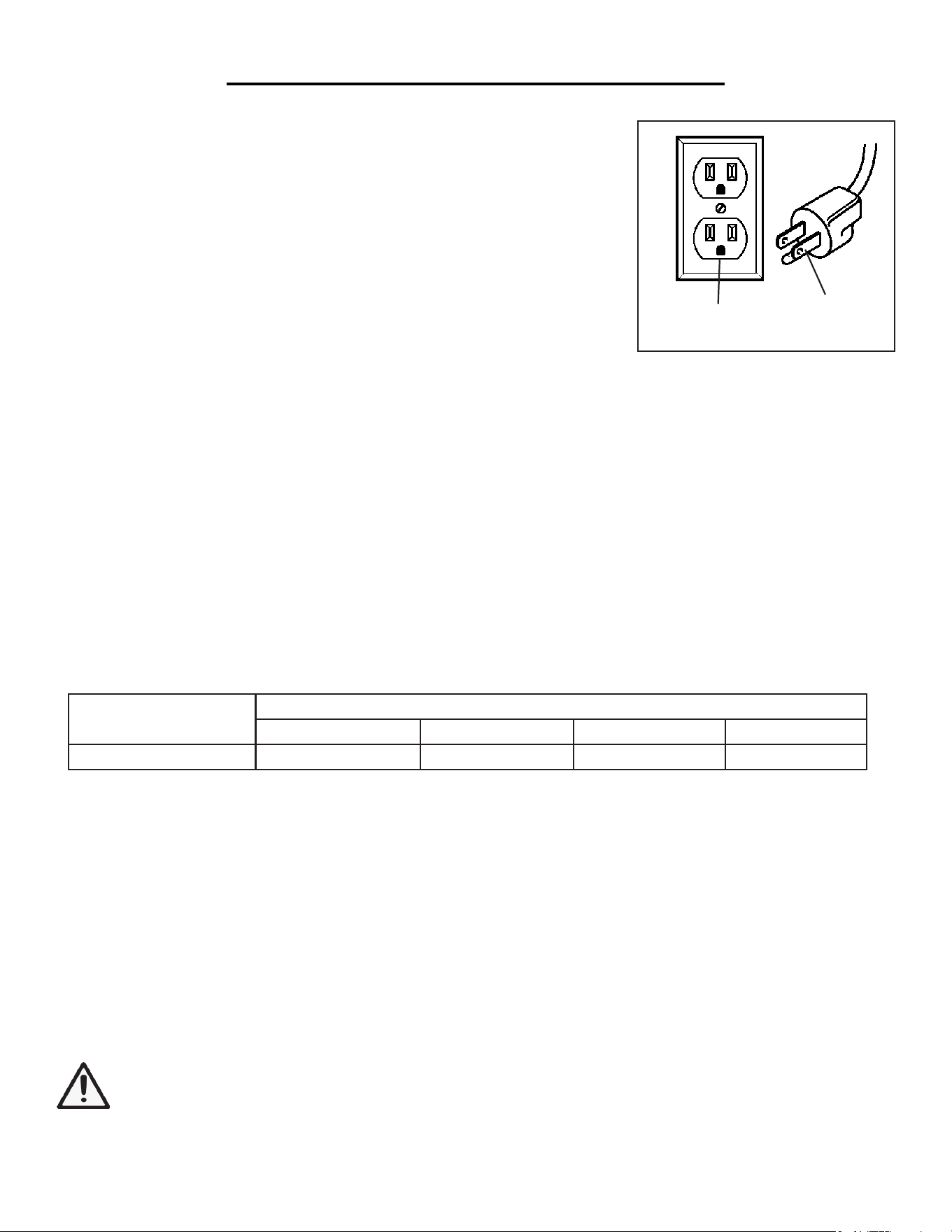
USE ONLY THREE-WIRE EXTENSION CORDS that have three-pronged plugs and outlets that accept the
tool’s plug as shown in Fig. A. Repair or replace a damaged or worn cord immediately.
Use a separate electrical circuit for your tools. This circuit must not be less than a #12 wire and should be protect-
ed with a 15 A time-delayed fuse. Before connecting the motor to the power line, make sure the switch is in the
OFF position and the electric current is rated the same as the current stamped on the motor nameplate. Running
at a lower voltage will damage the motor.
Grounded
Outlet
3-Prong
Plug
AMPERAGE
REQUIRED GAUGE FOR EXTENSION CORDS
25 ft. 50 ft. 100 ft. 150 ft.
9.5A 18 gauge 16 gauge 14 gauge 12 gauge
ELECTRICAL INFORMATION
7
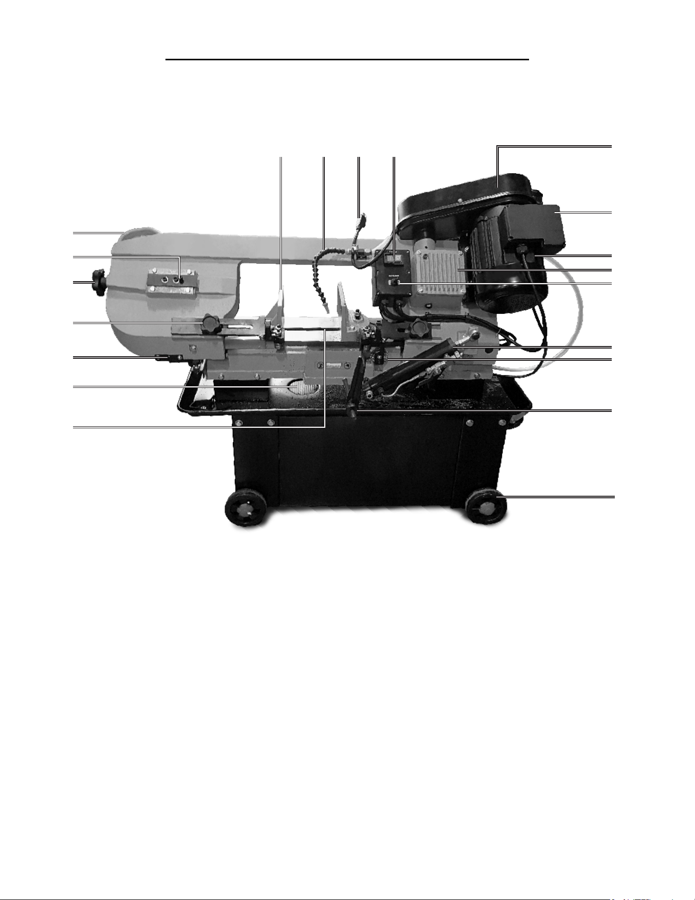
KNOW YOUR METAL BAND SAW
Carefully remove the tool and all contents from the packaging. Check all components and compare against the
diagram below. If any part is damaged or missing, please contact our customer service at (800) 232-1195, M-F 8-5
CST or email us at [email protected].
• Wheel x 4
• Wheel Axle x 2
• Cotter Pin x 8
• Filter Plate
1
2
3
4
5
6
7
8
9
10
1
Belt Cover
Electrical Box
Motor
Gear Box
Coolant Switch
Hydraulic Cylinder
Wire Brush
Work Stop
Transportation Wheel
Saw Blade
11
12
13
14
15
16
17
18
19
20
Drain Filter
Blade Cover (Behind)
Blade Guide Adjustment Knob
Blade Tension Knob
Belt Tracking Mechanism
Operation Handle
Adjustable Vise
Coolant Tube
Power Plug
ON/OFF Switch
• Hydraulic Cylinder Support Rod
• Hydraulic Cylinder
• Work Stop Support Rod
• Work Stop
2
3
4
5
6
7
8
9
10
11
12
13
14
15
16
17 18
PACKING LIST
19 20
8
UNPACKING THE MACHINE
WARNING: This big boy is very heavy, so you will need a muscular friend (or a trustworthy foe) to help
you lift and assemble the machine.
1. Prepare a sturdy and level surface on the ground that can support the weight of the machine (over 300 lbs). Open
the crate and unbolt the machine from the skid.
2. Prepare some supporting blocks (1-1/2 to 2 inches thick) to place under the saw base. This will elevate the ma-
chine so the wheels can be installed. Carefully lift the machine from the skid and place it onto the supporting blocks,
making sure the machine is stable.
CLEANING THE SURFACES
Your tool comes protected with a layer of anti-rust coating. Wipe off the coating and clean surfaces with kerosene,
diesel oil, or a mold solvent. DO NOT use cellulose-based solvents such as paint thinner or lacquer thinner, as
these will damage the painted surfaces. Then, apply a light layer of good-quality machine oil onto surfaces to protect
from rust and corrosion.
INSTALLING THE WHEELS
1. With the machine elevated on supporting blocks, slide the wheel axle through the holes in the saw stand. Use a
rubber mallet to push the axle all the way through.
ASSEMBLY
WARNING: To prevent injury from accidental operation, make sure the tool is switched OFF and un-
plugged from the power source before assembling the tool or making any adjustments.
Fig. 1
Fig. 2
2. Attach the wheels onto the ends the axle. Secure the
each wheel with two cotter pins, one on each side of the
wheel. Push the cotter pins fully through the transverse
holes in the axle.
3. Repeat to install the other two wheels.
4. Now carefully lift the saw from the supporting blocks
and place it on the ground.
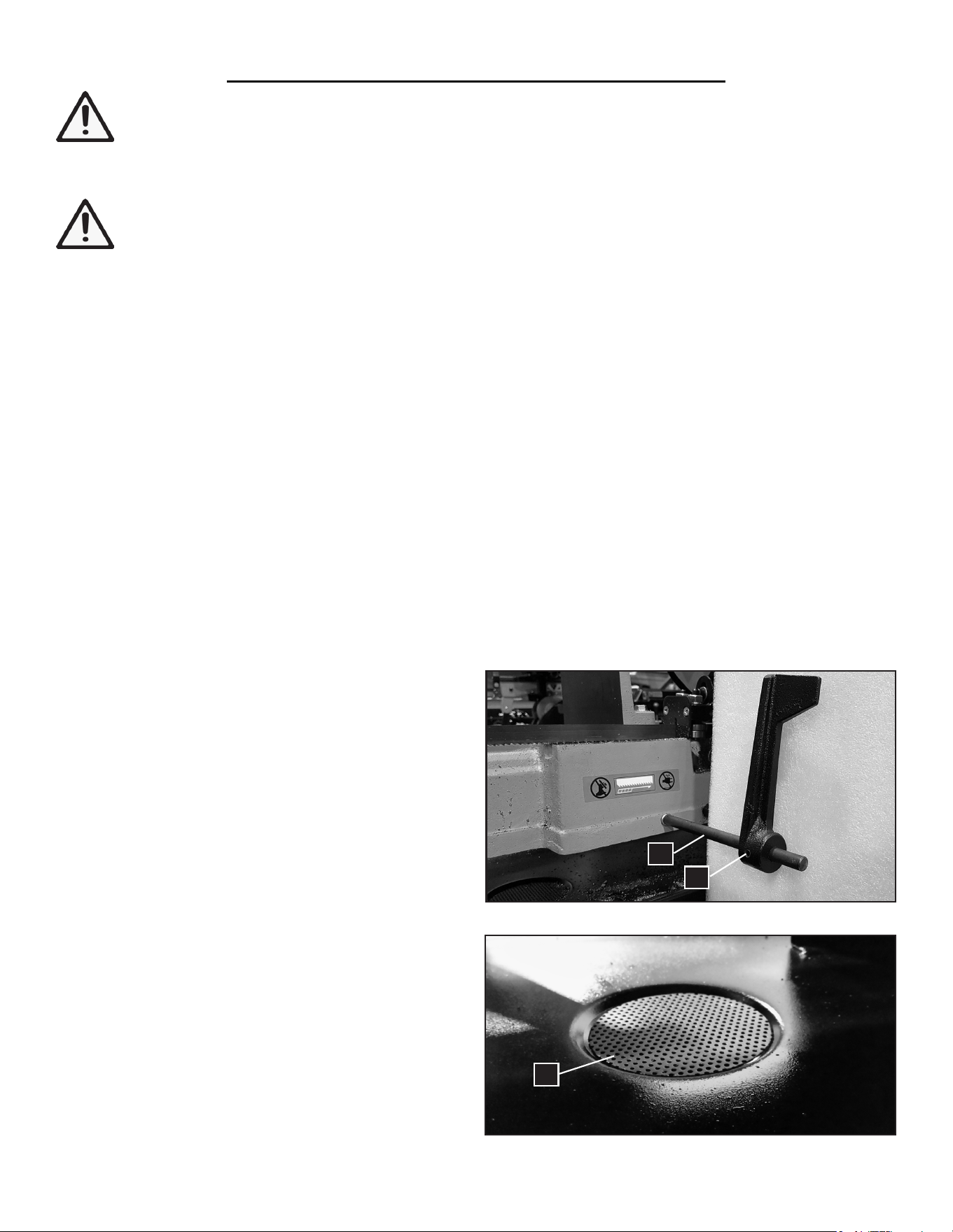
INSTALLING THE WORK STOP
1. Thread the work stop support rod (Fig. 1 - 1) into the
center hole on the saw base.
2. Slide the work stop onto the rod with the flat side fac-
ing the saw body. Fully tighten the set screw (Fig. 1 - 2).
PLACING THE DRAIN FILTER
Place the drain filter (Fig. 2 - 1) over the hole in the
chip tray below the saw base. The drain filter can catch
2 mm chips. You can add a finer mesh underneath this
filter to catch smaller chips.
2
1
1
9
ASSEMBLY
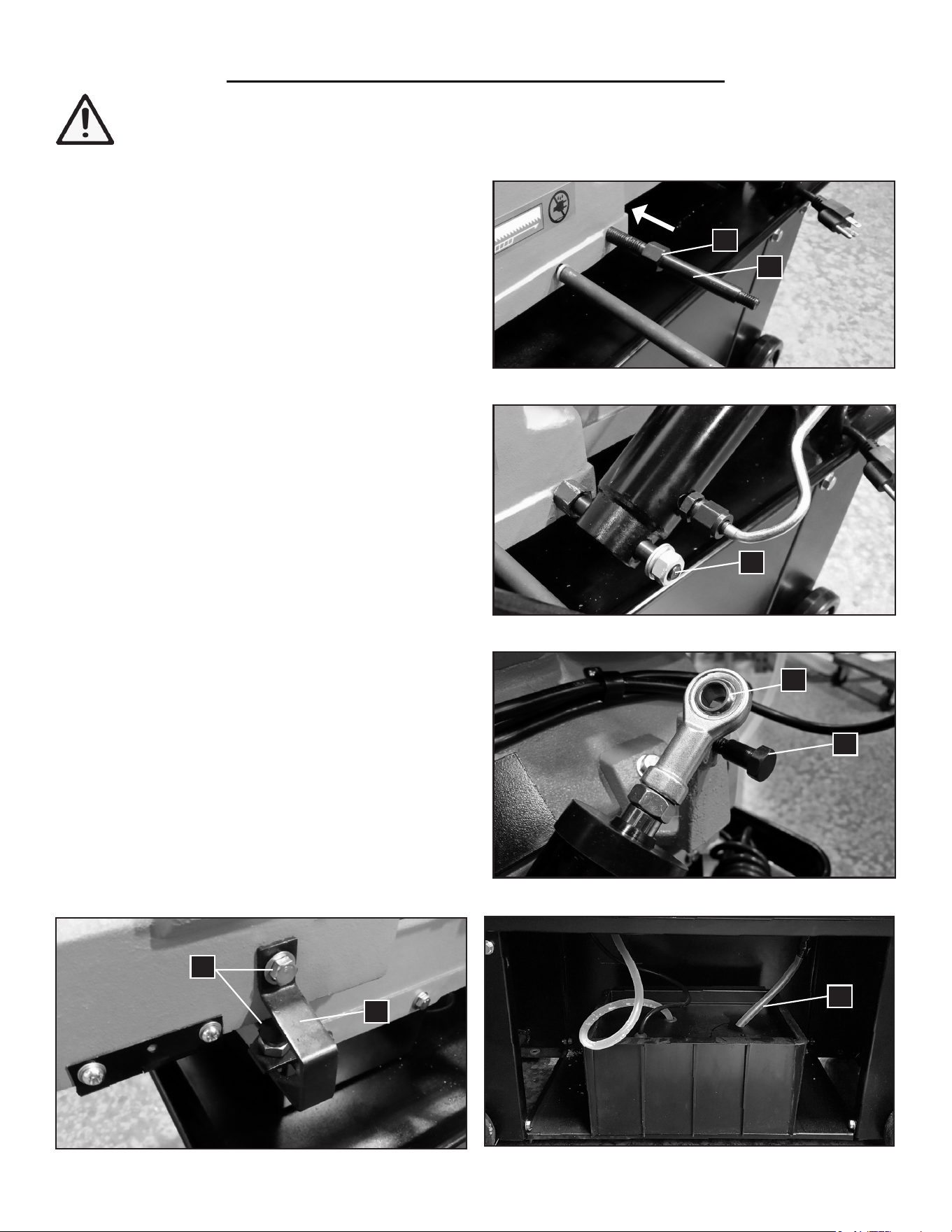
INSTALLING THE HYDRAULIC CYLINDER
1. Insert the hydraulic cylinder support rod (Fig. 3 - 1)
into the saw base. Thread the rod in fully so that the stop
nut (Fig. 3 - 2) is against the saw body.
2. Install the bottom of the hydraulic cylinder onto the
rod and secure with the washer and nut (Fig. 4 - 1).
3. Remove the top bolt (Fig. 5 - 1) from the machine and
insert it through the bore on the top of the cylinder (Fig.
5 - 2). Reinstall the bolt and tighten.
COOLANT TANK PREPARATION
1. Slide out the coolant tank (Fig. 6) from the back of the
saw stand. Remove the coolant return hose (Fig. 6 - 1)
and carefully remove the lid from the tank.
3. Fill the tank to approximately 80% of capacity with
water-soluble coolant. Follow the manufacturer’s instruc-
tions for your chosen coolant to obtain the proper mix-
ing ratio.
CAUTION: Do not use black cutting oil. Check cool-
ant daily and refill or replace as necessary.
4. Replace the lid and return the coolant tank to its place.
REMOVING THE LOCKING BRACKET
The saw is shipped with a locking bracket (Fig. 7 - 1) on
the front of the saw holding the saw arm shut. Remove
the top and lower nut to remove the bracket (Fig. 7 - 2).
This will allow you to raise the saw arm.
WARNING: To prevent injury from accidental operation, make sure the tool is switched OFF and un-
plugged from the power source before assembling the tool or making any adjustments.
Fig. 3
Fig. 4
Fig. 5
Fig. 6 Fig. 7
2
2
2
1
1
1
1
10
1
PREPARATION & ADJUSTMENTS
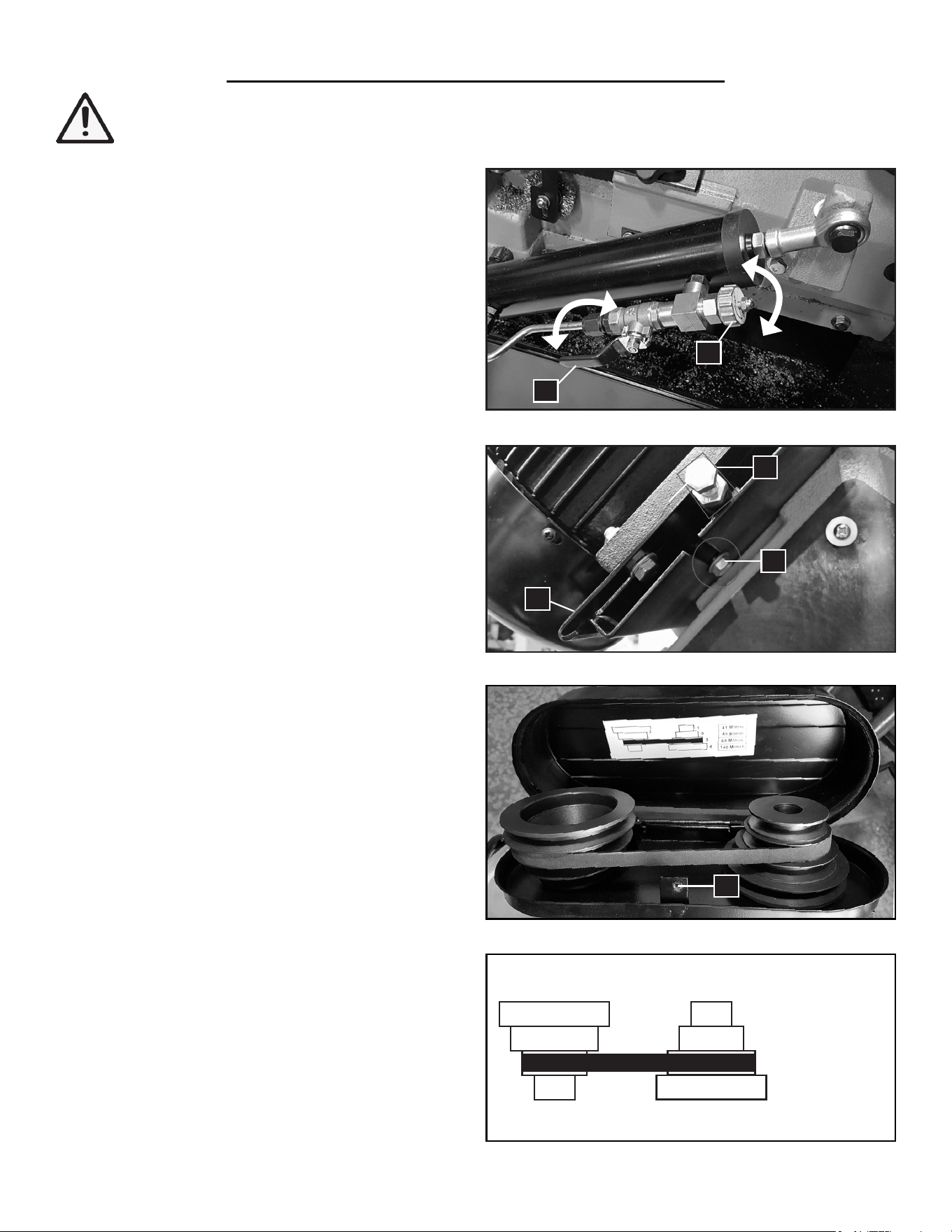
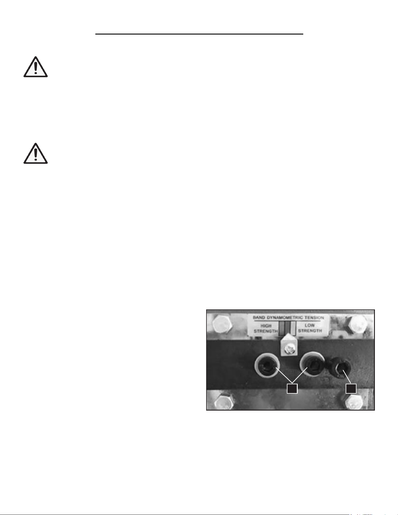
CONTROLLING THE HYDRAULIC SYSTEM
The hydraulic system is used to control the blade’s feed
rate and to lock the saw arm in the raised position. The
hydraulic lever (Fig. 8 - 1) controls whether the cylinder
is ON or OFF. The adjustment knob (Fig. 8 - 2) con-
trols the how fast the saw arm comes down.
1. To turn OFF the flow of hydraulic fluid, turn the
hydraulic lever (Fig. 8 - 1) clockwise (pointing upwards,
perpendicular to the cylinder axis). This will lock the
saw arm in the raised position.
2. To turn ON the flow of hydraulic fluid, turn the hy-
draulic lever (Fig. 8 - 1) counterclockwise. This will al-
low the saw arm to come down from the raised position.
3. To DECREASE the feed rate, turn the adjustment
knob (Fig. 8 - 2) clockwise (towards SLOW).
To INCREASE the feed rate, turn the adjustment knob
(Fig. 8 - 2) counterclockwise (towards FAST).
WARNING: To prevent injury from accidental operation, switch OFF and unplug the tool before making
any adjustments.
Fig. 8
Fig. 9
1
2
3
4
Fig. 10
Fig. 11
135 FPM
160 FPM
240 FPM
390 FPM
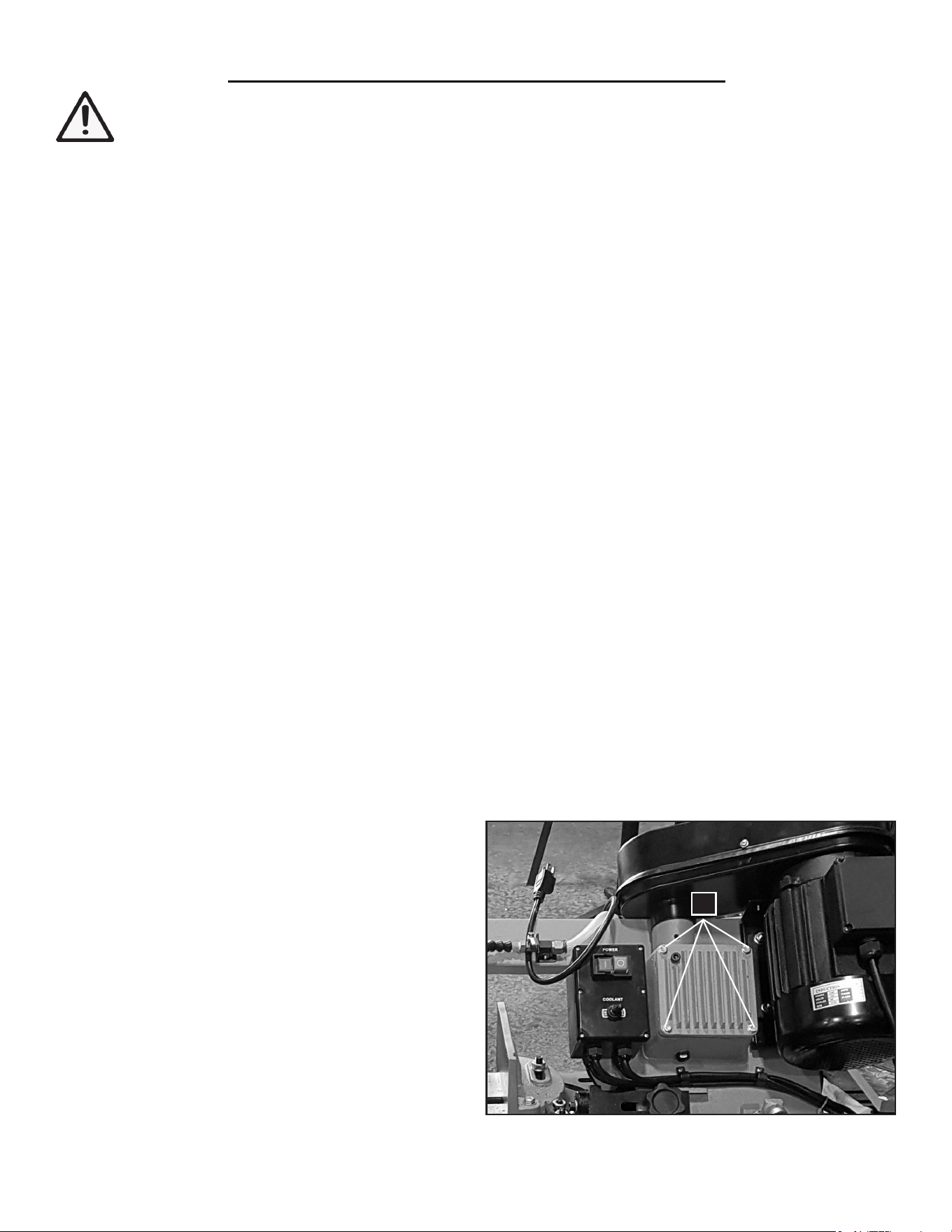
CHANGING THE BLADE SPEED
The band saw is capable of running the blade at 135,
160, 240 and 390 FPM. Adjust the blade speed by
changing the v-belt placement.
1. Loosen the motor lock screw on the rightmost side
of the machine (Fig. 9 - 1). Loosen the motor slide
screw (Fig. 9 - 2) underneath the motor plate enough to
permit the motor to slide.
2. Slide the motor plate (Fig. 9 - 3) to reduce belt ten-
sion and enable belt changing. You may need to tap the
plate with a rubber mallet.
3. Remove the Phillips head screw (Fig. 10 - 1) and
washer to open the belt cover, located above the motor.
4. Referring to the speed label (Fig. 11), position the
belt into the desired pulley combination for your se-
lected speed. Close the cover and reinstall the washer
and screw.
5. Slide the motor plate back into position. Then tight-
en the slide screw and lock screw.
1
2
3
1
1
2
11
PREPARATION & ADJUSTMENTS
WARNING: To prevent injury from accidental operation, switch OFF and unplugged the tool before
making any adjustments.
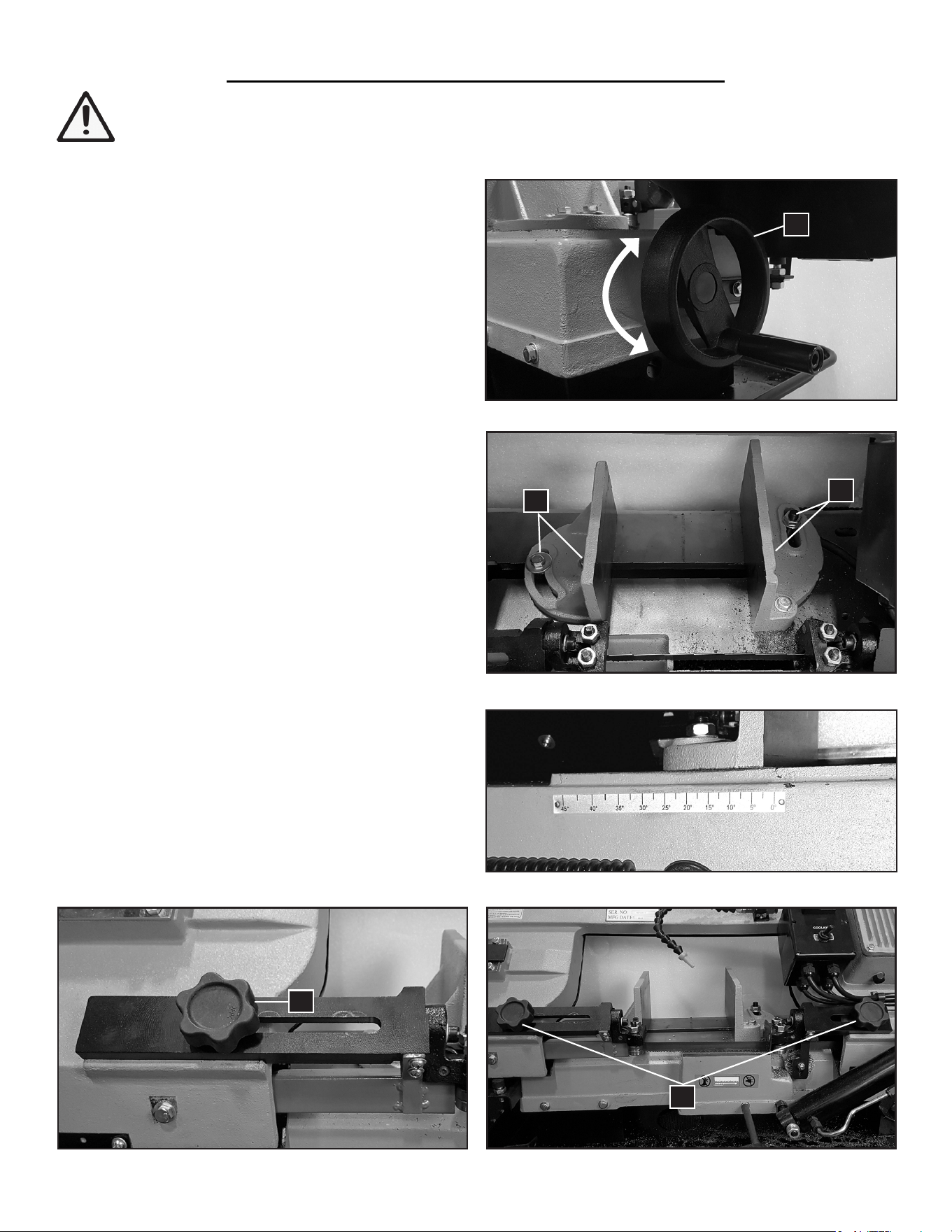
ADJUSTING THE VISE
The position and angle (0 to 45 degrees) of the vise can
be adjusted to securely hold your workpiece in place.
To adjust the position of the left movable jaw:
1. Locate the vise adjustment wheel (Fig. 12 - 1) on the
left side of the saw base.
2. Rotate the wheel clockwise to move the jaw towards
the center (tighten). Rotate the wheel counterclockwise
to move the jaw away from the center (loosen).
To adjust the angle of the jaws:
1. Loosen the bolts on the jaws (Fig. 13 - 1).
2. Tilt the jaws to the desired angle. You can refer to the
angle scale on the back of the saw base (Fig. 14).
3. Tighten the bolts to lock the jaws in place.
ADJUSTING THE BLADE GUIDE BRACKETS
There are two blade guide assemblies (Fig. 15 - 1) on the
left and right of the exposed blade. Adjust the position of
the blade guides to just clear the workpiece.
1. Loosen the blade guide adjustment knobs (Fig. 16 - 1)
2. Slide the blade guides assemblies as close as possible
to the workpiece, without interfering with the cut.
3. Tighten the knobs to lock the blade guides in place.
Fig. 12
Fig. 13
Fig. 14
Fig. 15 Fig. 16
1
1
1
1
1
12
PREPARATION & ADJUSTMENTS
WARNING: To prevent injury from accidental operation, switch OFF and unplugged the tool before
making any adjustments.
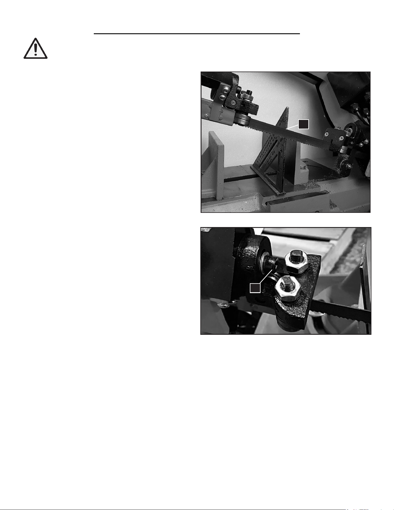
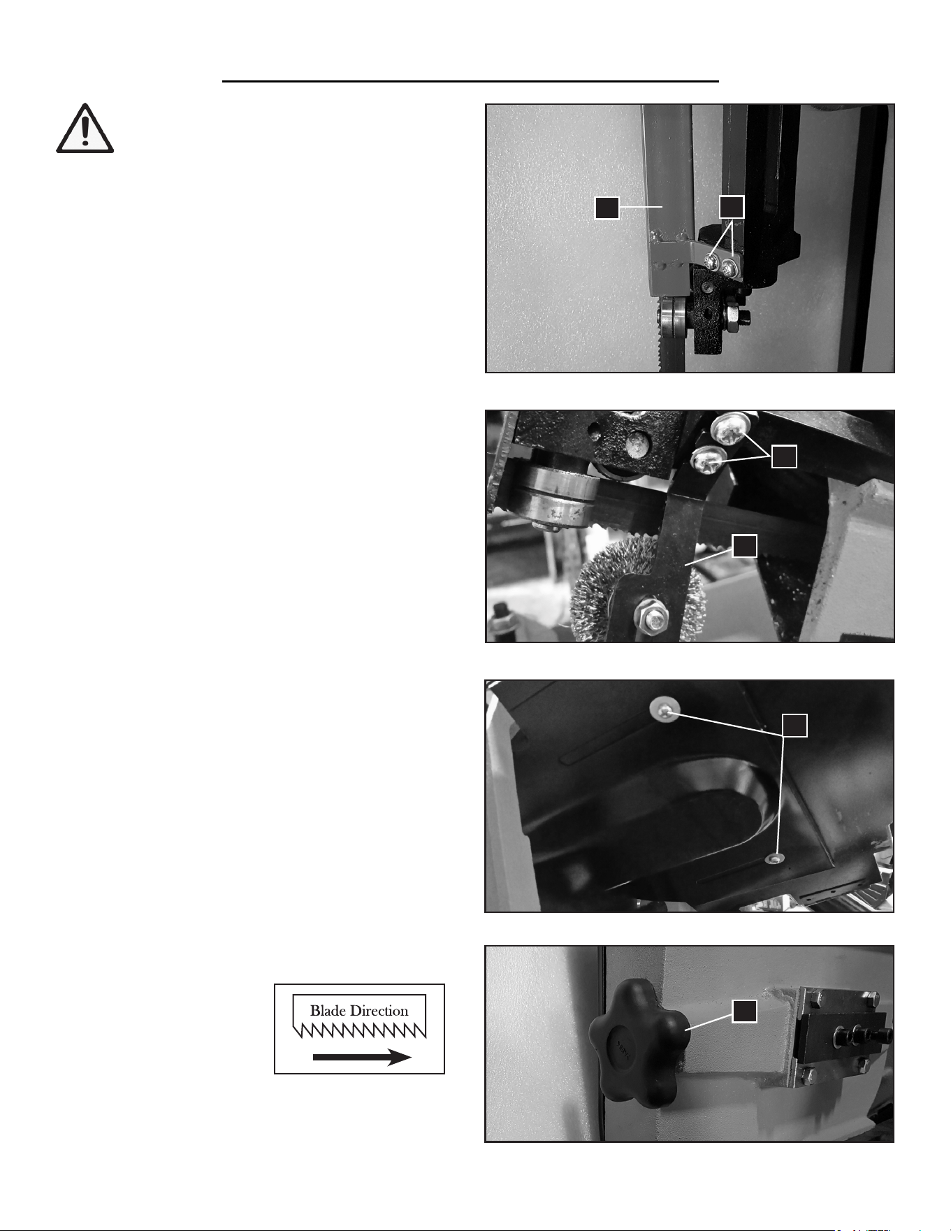
SQUARING THE BLADE TO THE TABLE
1. Raise the saw arm slightly and turn OFF the hydrau-
lic valve to lock the saw arm in place.
2. Move the blade guide brackets (Fig. 15 - 1) closer to
the center of the blade for easier adjustments. Tighten
the blade guide knobs (Fig. 16 - 1)
3. Place a square (combination, machinist’s, etc.) flat
on the table against the blade (Fig. 17 - 1).
4. Check if the blade makes contact with the square
along the entire width of the blade.
5. If adjustment is necessary, loosen the set screws
(Fig. 18 - 1) on the left and right blade guide assem-
blies using a hex wrench. Slightly rotate the both blade
guide assemblies in the same direction, until the blade
makes contact with the square along its entire width.
NOTE: To help adjust and tighten the blade guide
assemblies, you can take a pair of locking pliers and
clamp it on to the black part (Fig. 18 - 2) of the as-
sembly. Hold the locking pliers to adjust the blade
guide angle with one hand and tighten the set screw
with the other hand.
6. Tighten both set screws (Fig. 18 - 1).
NOTE: If adjustments are made to alter the blade-to-
SQUARING THE VISE TO THE BLADE
NOTE: Only perform this step after the blade has been squared to the table, as the blade is being used as the
reference in this step.
1. Place a square (combination, machinist’s, etc.) flat against the blade and the vise.
2. Check if the square lies along the entire length of the vise and blade without a gap.
3. If adjustment is necessary, loosen the vise adjustment bolts (Fig. 13 - 1) and adjust the vise so that it is square to
the blade.
4. Tighten the vise adjustment bolts (Fig. 13 - 1).
Fig. 17
Fig. 18
1
1
13
table alignment, be sure to check the blade guide bearings (see “Adjusting the Blade Guide Bearings” on the next
page).
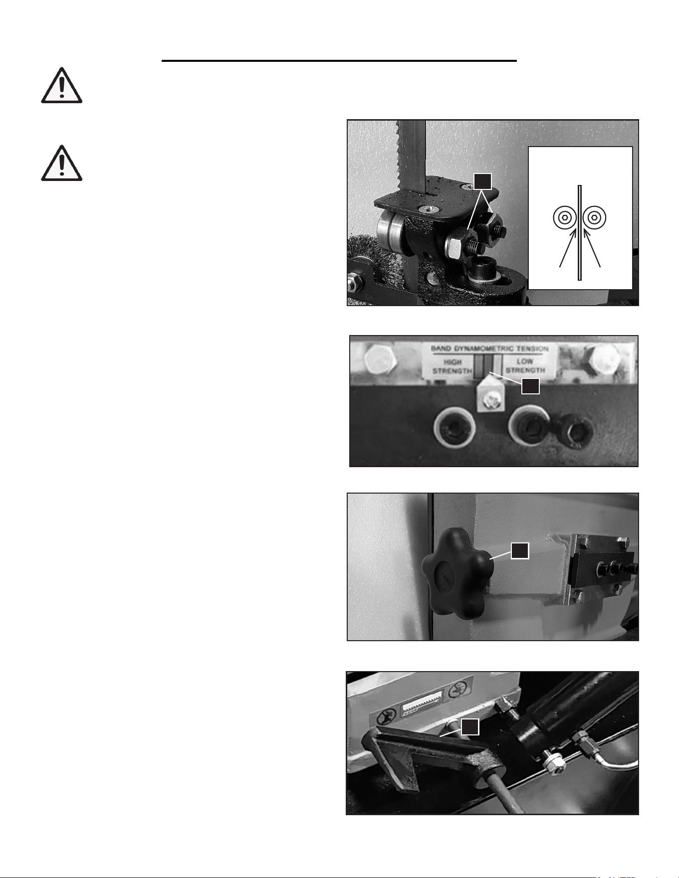
ADJUSTING THE BLADE GUIDE BEARINGS
WARNING: Saw blades are sharp. Wear
work gloves when handling saw blades to
prevent injuries.
1. Raise the saw arm to the raised position and lock it in
place by turning OFF the hydraulic valve.
2. Adjust the position of the two side bearings by turn-
ing the hex nuts (Fig. 19 - 1) so that the bearings are as
close to the blade as possible without actually touching it
(approximately 0.25 mm from the blade). You can use
a folded piece of paper to guide the distance. The blade
should move up and down freely when grasped by the
hand and not interfere with the roller bearings.
PREPARATION & ADJUSTMENTS
WARNING: To prevent injury from accidental operation, switch OFF and unplugged the tool before
making any adjustments.
SETTING THE WORK STOP
Set the work stop (Fig. 21 - 1) to the desired distance
and tighten the set screw. The work stop enables you to
accurately cut multiple pieces to the same length.
Fig. 19
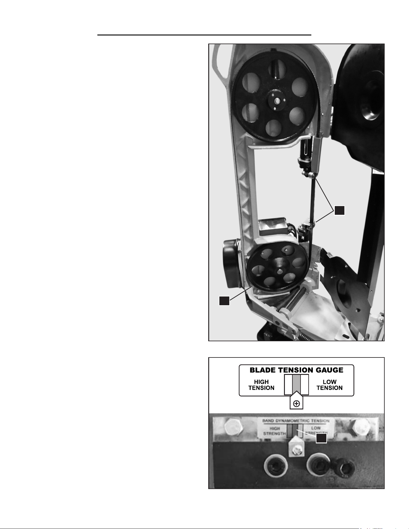
ADJUSTING THE BLADE TENSION
Correct blade tension is important for proper opera-
tion of the saw. The blade should be properly tensioned
during production. Check your blade tension using the
blade tension gauge (Fig. 20 A) on the front of the saw.
The blade tension is correct if the arrow points to the
center green box of the gauge (Fig. 20 A - 1). If the arrow
points to the left red box, that means the blade tension
is too high; pointing to the right yellow box means the
blade tension is too low.
To add tension, turn the blade tension knob on the left
side of the saw (Fig. 20 B - 1) clockwise; to reduce ten-
sion, turn the knob counterclockwise. Adjust until the ar-
row points to the center green box on the tension gauge.
CAUTION: Do not over tighten the blade. Overtight-
ening will cause the blade to stretch and warp.
Fig. 20 B
Fig. 21
3. Repeat to adjust the side guide bearings on the other
blade assembly.
1
1
1
14
Side Guide
Bearings
0.25 mm0.25 mm
Fig. 20 A
1
PRIOR TO OPERATION
1. Check the workpiece:
• The workpiece is within the cutting capacity of the saw.
Cutting capacity @ 90 degrees: 7 in. (round stock), 7 x 12 in. (rectangular stock).
Cutting capacity @ 45 degrees: 3-15/16 in. (round stock), 4-1/3 x 6-1/4 in. (rectangular stock).
• Cuts cannot be performed on a sharp edge. File any sharp edge off of the workpiece before cutting.
• The workpiece is held securely inside the vise.
• Both blade guide assemblies are as close the workpiece as possible to minimize side-to-side blade movement.
2. Check the blade:
• The blade is properly installed and seated on the wheels close to the peripheral wheel flanges.
• The blade is properly tensioned.
• The blade tooth direction matches the diagram on the saw body.
• The blade guide side bearings as close to the blade as possible without touching it.
Check both blade guide assemblies.
3. Check the blade speed:
The belt arrangement has been set to the suitable cutting speed (refer to the instructions on page 11).
4. Check the feed rate:
With the machine turned OFF, turn ON the hydraulic lever and raise the saw arm. Watch the rate the saw arm
falls down and rotate the adjustment knob to adjust the feed rate.
5. Check coolant:
The coolant level is adequate and the coolant is not contaminated.
OPERATION
Fig. 22
WARNING: To prevent serious injury, make sure all the warnings and instructions have been read and
understood before operating this tool.
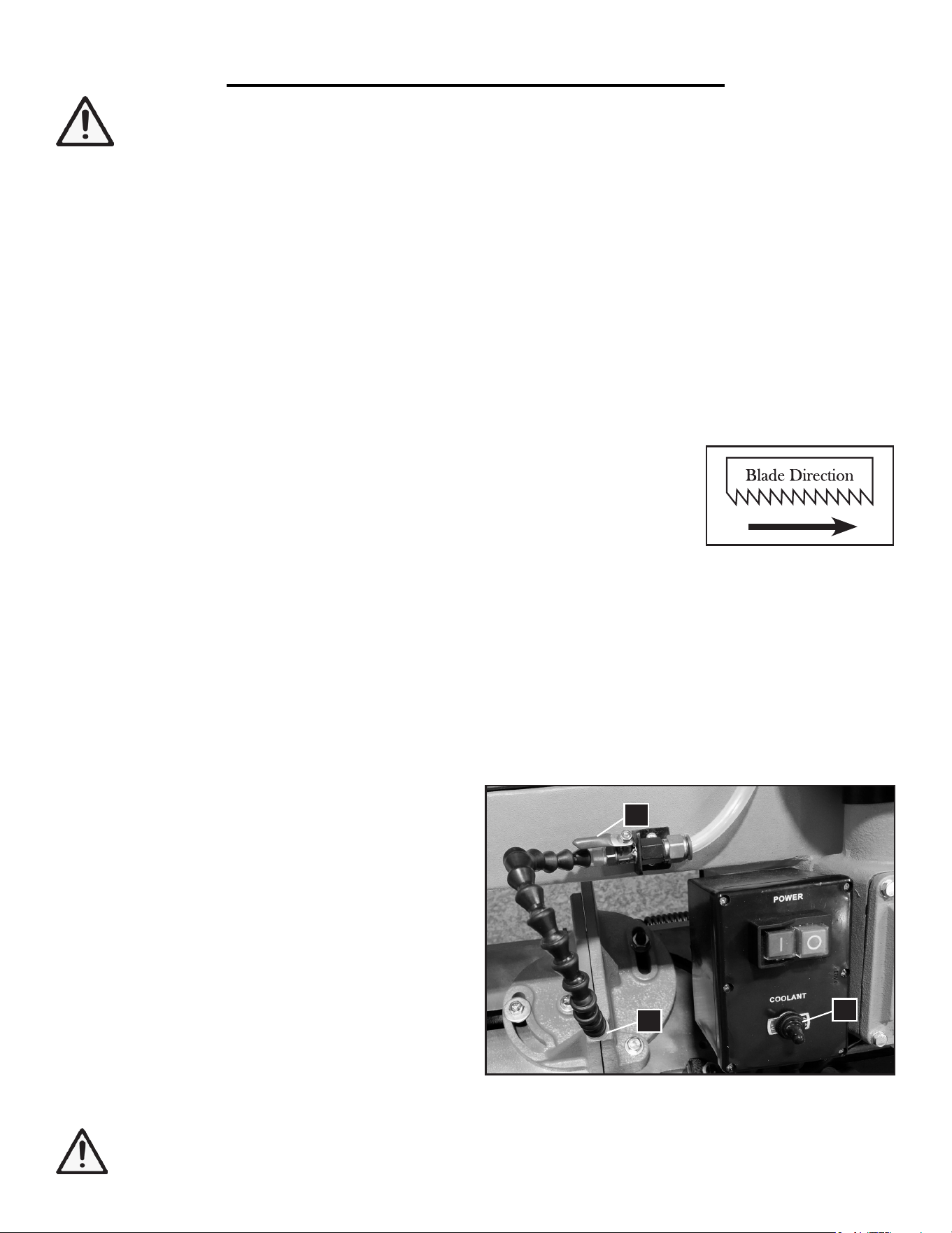
CONTROLLING THE COOLANT SYSTEM
The coolant system allows coolant to be drawn from the
tank and dispensed through the tube to cool down the
blade during cutting.
Adjust the tube so that the nozzle (Fig. 22 - 3) is directed
towards the point of cut.
To use coolant, the motor must be turned ON. Open
the coolant lever (Fig 22 - 2; move it clockwise until it is
parallel to the tube) and flip the coolant switch (Fig. 22 -
1) to ON.
NOTE: The coolant may splash around the work area.
Be prepared to get messy.
3
2
1
15
WARNING: When cutting magnesium, NEVER use water-soluble oils or emulsions (oil-water mix). The
water will greatly intensify any accidental magnesium chip fire and cause danger.
1. Turn OFF the hydraulic valve and raise the saw arm to the appropriate height.
2. Position the workpiece to be cut against the work stop. Make sure it is firmly gripped by the vise.
3. Plug in the power plug and press the green button start the machine. Move the coolant lever parallel to the tube
and then flip the coolant switch to ON.
4. Allow the blade to reach full speed. Then, turn ON the hydraulic valve to allow the saw arm to come down.
Give the saw some time to cut through the workpiece. Keep your hands and other body parts AWAY from the
blade.
CAUTION: Never start a cut with the blade in contact with the workpiece.
NOTE: The metal chips should be curled and silvery. If the chips are thin and powder-like, increase your feed
rate. If the chips are burned, reduce the blade speed.
5. When the cut is complete, the motor should stop automatically. Turn OFF the machine by pressing the red
button. Wait until the blade has completely stopped before moving the workpiece.
CAUTION: Avoid touching the cut surfaces or the blade; they can be very hot.
7. Repeat steps 1 to 6 to resume cutting.
8. When all cutting is complete, make sure the saw arm is returned to the horizontal position, the power is turned
OFF, and the machine is unplugged from the outlet. Follow the instructions in “General Maintenance” on the
next page to clean and maintain your machine.
NOTE: Release the blade tension at the end of each workday to prolong blade life.
OPERATION
OPERATING THE SAW
WARNING: This machine is only used for HORIZONTAL metal cutting. Do not use this saw for verti-
cal cutting or woodworking cutting.
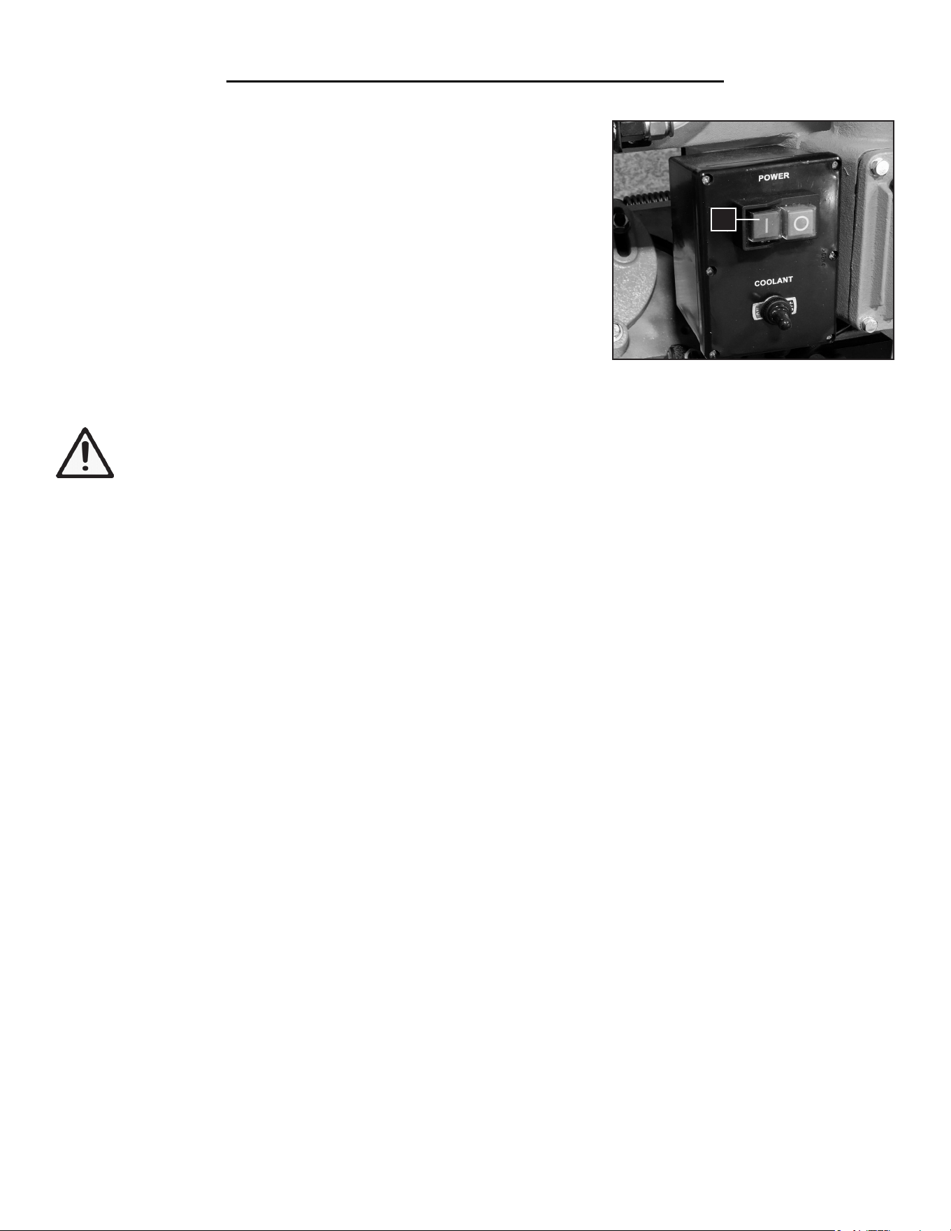
ON/OFF SWITCH & AUTOMATIC SHUTOFF
Press the green button (I) (Fig. 23 - 1) to turn ON the motor. Wait for the
blade to reach full speed before allowing the blade to enter the workpiece.
This machine has an automatic shutoff function that will stop the motor
when the saw arm has come down to the horizontal position. To resume
cutting, raise the saw arm and press the green button (I) again to start.
To turn OFF the machine, press the red button (O). Before making any
adjustments, removing workpieces or leaving the work area, always make
sure to turn OFF and unplug the machine, and wait for the blade to stop
completely.
16
Fig. 23
1
MAINTENANCE
REPLACING THE OIL
If the saw is undergoing normal usage, replace the oil
approximately once every year. The oil quantity is 5 to
6.7 fl. oz. (150 to 200 ml). For professional or industrial
use, replace more often. The gear box oil type used
with your band saw is L-CKE 150# gear oil.
To access the oil, open the gearbox by removing the
four screws (Fig. 24 - 1). Prepare a container below the
gear box and open the gear box cover. Be careful, as
the oil may pour out when the cover is removed. Drain
the oil into the container and replace with fresh gear oil.
NOTE: The gear box may be air tight and not easy to
open.
GENERAL MAINTENANCE
1. Keep all surfaces clean and free of rust, chips and coolant buildup. At the end of each work day, vacuum sawdust
and clean the machine with a dry cloth or brush. Use a small paintbrush or parts cleaning brush to remove metal
particles. Keep blade guides clean and free of metal chips/residue.
NOTE: Do not use compressed air to clean the band saw. Compressed air may force chips into the guide bearings
and other critical areas of the machine.
2. Periodically check that all nuts and bolts are tight.
3. Routinely check the condition of the power supply cords and replace them if they are broken, worn or if internal
wires are showing.
4. To ensure effective machine operation, check the condition of the blade daily. Sharpen or replace the saw blade
as necessary. Check guide bearings frequently to make sure they are properly adjusted and turning freely.
5. Your may release the blade tension at the end of each workday to prolong blade life.
6. Check and refill coolant. Low coolant level can cause foaming and high blade temperatures. Dirty or weak cool-
ant can clog the pump and damage the blade. Dirt in the coolant can also contribute to the growth of bacteria that
can cause skin irritation.
7. During unpacking, you should have applied a coat of good quality light machine oil to the machine. Reapply
machine oil as necessary to protect the machine from rust and corrosion.
8. If you do not intend to use the machine for a long time, clean it and store it in a dry place. Release the blade ten-
sion and make sure the blade stays slack so that it is not kept under tension during storage.
WARNING: Disconnect the machine from the power source before making any maintenance or adjust-
ments. Failure to do so may result in serious injury.
1
Fig. 24
17
WARNING: The blade is sharp and springy.
Make sure to wear work gloves and safety
glasses. The blade may bounce back and hit
you during installation. Wear long work pants and long
sleeve shirt to protect yourself from injuries.
CHANGING THE SAW BLADE
NOTE: The machine is designed to be used with
blades that are 93" long, 3/4" width and 0.032" thick
(2360 x 19 x 0.9 mm). Use of blades with different
specifications may not fit or cause inferior perfor-
mance. Replacement metal band saw blades can be
purchased from wenproducts.com.
1. Slowly raise the saw arm to the raised position and
turn OFF the hydraulic lever to lock it in place.
2. Remove the red blade guard assembly (Fig. 25 - 1) by
removing mounting screws and washers (Fig. 25 - 2).
Be sure to reinstall the blade guard later.
3. Remove the wire wheel assembly (Fig. 26 - 1) by
loosening two screws and washers (Fig. 26 - 2).
4. Open the blade cover by removing the cover screws
and washers from the back of the saw.
5. Loosen the drive wheel cover screws (Fig. 27 - 1) to
permit adjustment of the drive wheel cover as the blade
cover is opened.
6. Loosen the blade tension by turning the blade
tension knob (Fig. 28 - 1) counterclockwise.
7. Carefully remove the old blade. Blade teeth are sharp
and must be handled with gloves.
8. Install the new blade. Place the blade between the
blade guide bearings first (Fig. 29 - 1). Make sure the
blade teeth are facing
outwards and in the same
direction as indicated on
the saw arm label.
CAUTION: The blade is quite springy, and will want
to spring out from between the bearing guides, which
could cause injury. Wear eye protection, gloves, long
sleeves and long pants.
MAINTENANCE
Fig. 25
Fig. 26
Fig. 28
Fig. 27
2
1
1
1
2
1
18
CHANGING THE SAW BLADE (CONT.)
9. Carefully wrap the blade around the bottom wheel
(Fig. 29 - 2). Hold the blade around the bottom wheel
with one hand and slip it around the top wheel with the
other hand, keeping the blade between the blade guide
bearings. The blade should be positioned next to but
not tightly against the wheel flange.
10. Turn the blade tension knob (Fig. 28 - 1) clockwise
to tension the blade just enough so that the blade will
NOT slip on the wheels upon startup. Do not over ten-
sion the blade.
11. Close the blade cover door and secure with the
cover washers and screws. Re-tighten drive wheel cover
screws (Fig. 27 - 1).
12. Reattach the red blade guard (Fig. 25 - 1) and wire
brush assembly (Fig. 26 - 1).
13. Refer to the next section “Adjusting the Blade Ten-
sion” for setting the blade tension for your new blade.
MAINTENANCE
ADJUSTING THE BLADE TENSION
Correct blade tension is important for proper operation
of the saw. To set the blade tension for a new blade:
1. After a new blade has been installed, ensure that the
blade has been roughly tensioned according to step 10
above and does not slip on the wheels. Make sure all
covers are closed and all guards are in place.
2. Connect the machine to the power source. Run
Fig. 29
Fig. 30
the saw for 2 to 3 minutes to allow the blade to seat
properly on the wheels. Turn OFF and disconnect the
machine from the power.
3. Refer to the blade tension gauge (Fig. 30) for proper
tension of the blade. Adjust the blade tension using the
blade tension knob on the left of the saw (Fig. 28 - 1).
Turn the blade tension knob clockwise to add tension;
turn the knob counterclockwise to reduce tension, until
the blade tension gauge arrow points to the green box
(Fig. 30 - 1) on the center of the gauge.
CAUTION: Do not over tighten the blade. Over-
tightening will cause the blade to stretch and warp
1
2
19
1
ADJUSTING THE BLADE TRACKING
WARNING: Blade tracking adjustment requires running the saw with the back cover open. This adjust-
ment must only be completed by a qualified person. Failure to comply may cause serious injury.
Blade tracking has been set at the factory and should not require adjustment on your existing blade. If a tracking
problem occurs, before making any tracking adjustments, try replacing with a new blade (see page 20 “Changing
the Saw Blade”) and see if the tracking issue is resolved. Warped or worn blades will not track properly.
If the problem still persists, adjust the machine as follows:
WARNING: If the blade tension or tracking is improper, the blade can spring off, causing serious
injury. Stand behind the saw and cover at all times when adjusting blade tracking to minimize the risk of
injury. Make sure to wear safety glasses, work gloves, long work pants and long sleeve shirt.
1. Move the saw arm to the raised position and lock it in place by shutting OFF the hydraulic valve.
2. Confirm that the blade tension is set properly (see page 19 “Adjusting the Blade Tension”).
3. Open the back cover by removing the cover screws and washers.
4. Loosen the drive wheel cover screws (Fig. 27 - 1) to permit full opening of the cover.
5. Run the saw and observe the blade. The blade should run next to but not tightly against the wheel flange.
6. To adjust the blade tracking, loosen the two shaft locking bolts (Fig. 31 - 1).
7. Slowly turn the set screw (Fig. 31 - 2) with a hex wrench, while observing the blade tracking on the wheel.
MAINTENANCE
Fig. 31
1 2
Turn the set screw clockwise to track the blade closer to
the wheel flange.
Turn the set screw counterclockwise to track the blade
away from the wheel flange.
8. Once the blade tracking is complete, tighten the two
shaft locking bolts (Fig. 31 - 1).
9. Close the blade cover door and secure with the cover
washers and screws. Re-tighten drive wheel cover screws
(Fig. 27 - 1).
20
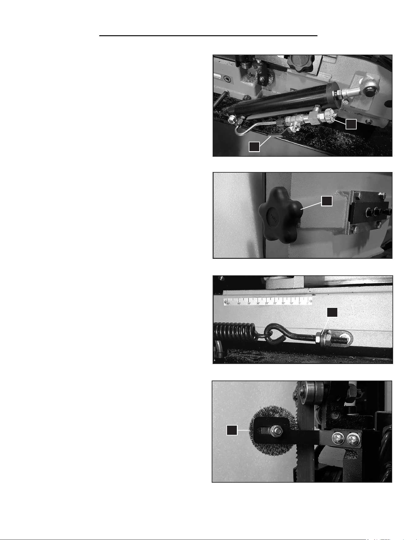
CHECKING & ADJUSTING THE BOW WEIGHT
MAINTENANCE
BLADE CLEANING BRUSH MAINTENANCE
The wire brush (Fig. 35 - 1) on the right side of the
blade helps to clean the saw blade during operation. It
is important that the blade cleaning brush is properly
adjusted and kept in good working order.
Replace the wire brush assembly (Part No. 39707-204)
if it becomes damaged or worn out. The blade life will
be greatly shortened if the blade cleaning brush is out
of adjustment, becomes damaged or becomes worn
out.
PRODUCT DISPOSAL
Used power tools contain recyclable materials and
should not be disposed with household waste. Please
take this product to your local recycling facility for re-
sponsible disposal and to minimize its environmental
impact.
Fig. 32
Fig. 33
Fig. 34
Fig. 35
The bow weight is a very important setting of the saw,
which has been set at the factory and should not need
any adjustment.
However, if the bow weight has not been set properly,
it can result in poor performance, crooked cuts, tooth
stripping, stalling and the blade popping off the blade
wheels. If adjustment is necessary:
1. Disconnect the machine from the power source.
2. Turn ON the hydraulic cylinder valve (Fig. 32 - 1)
and place the saw arm in the horizontal position.
3. Turn the feed rate valve (Fig. 32 - 2) of the hydraulic
cylinder counter-clockwise until it stops.
4. Place a fish-type scale under the blade tension
handle (Fig. 33 - 1) and lift the saw arm. The scale
should indicate approximately 11 - 13 lbs.
5. If adjustment is necessary, loosen the hex nut and
adjust the tension to approximately 11 - 13 lbs by turn-
ing the bow weight bolt (Fig. 34 - 1).
1
2
1
1
1
21
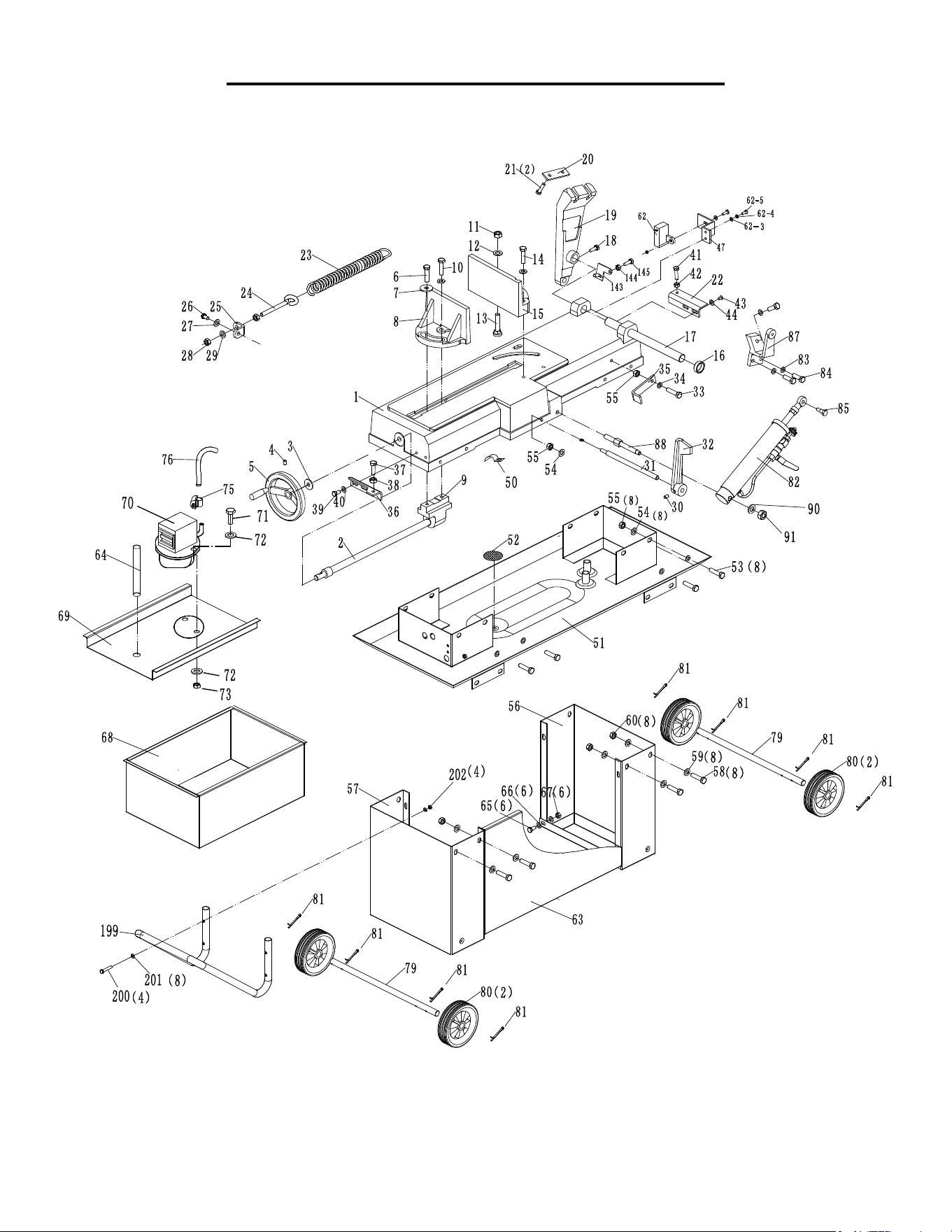
EXPLODED VIEW & PARTS LIST
22
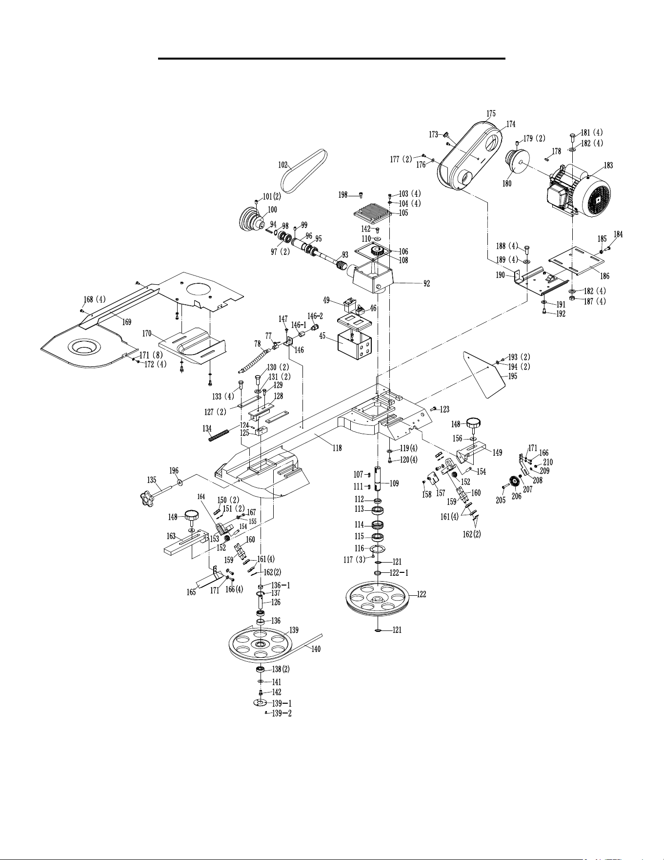
EXPLODED VIEW & PARTS LIST
23

EXPLODED VIEW & PARTS LIST
24
No. Part No. Description Qty
1 39707-001 Table 1
2 39707-002 Vise Screw 1
3 39707-003 Washer M16 1
4 39707-004 Hex Soc Set Screw M8x12 1
5 39707-005 Vise Handwheel 1
6 39707-006 Hex Hd Screw M10x40 1
7 39707-007 Washer M10 2
8 39707-008 Vise Jaw (Front) 1
9 39707-009 Vise Mounting Bracket 1
10 39707-010 Hex Soc Screw M10x40 1
11 39707-011 Hex Nut M12 1
12 39707-012 Washer M12 1
13 39707-013 Carriage Bolt 1
14 39707-014 Hex Hd Screw M10x40 1
15 39707-015 Vise Jaw (Rear) 1
16 39707-016 Bushing 1
17 39707-017 Pivot Rod 1
18 39707-018 Hex Bolt M8x20 1
19 39707-019 Pivot Bracket 1
20 39707-020 Pivot Bracket Plate 1
21 39707-021 Hex Hd Screw M10x40 2
22 39707-022 Support Plate, Right 1
23 39707-023 Spring 1
24 39707-024 Spring Adjusting Rod 1
25 39707-025 Spring Handle Bracket 1
26 39707-026 Hex Hd Screw M8x16 1
27 39707-027 Washer M8 1
28 39707-028 Hex Nut M10 1
29 39707-029 Washer M10 1
30 39707-030 Hex Soc Set Screw M8x12 1
31 39707-031 Stock Stop Rod 1
32 39707-032 Stop Block 1
33 39707-033 Hex Hd Screw M8x30 1
34 39707-034 Washer M8 1
35 39707-035 Support Plate, Front 1
36 39707-036 Support Plate, Left 1
37 39707-037 Hex Hd Screw M10x30 1
No. Part No. Description Qty
38 39707-038 Hex Nut M10 1
39 39707-039 Hex Hd Screw M8x16 2
40 39707-040 Washer M8 2
41 39707-041 Hex Hd Screw M8x30 1
42 39707-042 Hex Nut M8 1
43 39707-043 Hex Hd Screw M8x16 2
44 39707-044 Washer M8 2
45 39707-045 Electrical Box 1
46 39707-046 Coolant Switch 1
47 39707-047 Limit Switch Cover 1
49 39707-049 Power Switch 1
50 39707-050 Wire Retainer 1
51 39707-051 Coolant Pan 1
52 39707-052 Filter 2Mm 1
53 39707-053 Hex Hd Screw M8x30 8
54 39707-054 Washer M8 17
55 39707-055 Hex Nut M8 8
56 39707-056 Base Leg (Right) 1
57 39707-057 Base Leg (Left) 1
58 39707-058 Hex Hd Screw M10x20 8
59 39707-059 Washer M10 16
60 39707-060 Hex Nut M10 8
62 39707-062 Limit Switch 1
62-3 39707-062-3 Spring Washer M6 2
62-4 39707-062-4 Washer M6 5
62-5 39707-062-5 Round Hd Screw M6x16 3
62-6 39707-062-6 Hex Nut M6 1
63 39707-063 Base Panel 1
64 39707-064 Hose Id 16 Od 20 1
65 39707-065 Hex Hd Screw M8x16 6
66 39707-066 Washer M8 12
67 39707-067 Hex Nut M8 6
68 39707-068 Coolant Tank 1
69 39707-069 Pump Support 1
70 39707-070 Coolant Pump 1
71 39707-071 Hex Hd Screw M4x16 2
72 39707-072 Washer M4 2

EXPLODED VIEW & PARTS LIST
25
No. Part No. Description Qty
73 39707-073 Hex Nut M4 2
75 39707-075 Hose Clamp 2
76 39707-076 Hose Id 8 Od 12 1
77 39707-077 Coolant Valve 1/4” Npt 1
78 39707-078 Coolant Tube 1
79 39707-079 Axle 2
80 39707-080 Wheel 2
81 39707-081 Cotter Pins 8
82 39707-082 Hydraulic Cylinder 1
83 39707-083 Washer M8 3
84 39707-084 Hex Hd Screw M8x25 3
85 39707-085 Hex Hd Screw 1
87 39707-087 Cylinder Bracket 1
88 39707-088 Cylinder Support Rod 1
90 39707-090 Flat Washer M10 1
91 39707-091 Hex Nut M10 1
92 39707-092 Gear Box 1
93 39707-093 Worm Gear Shaft 1
94 39707-094 Key 5X5x55 1
95 39707-095 Bearing 6003Z 1
96 39707-096 Bearing Bushing 1
97 39707-097 Bearing 6003Z 2
98 39707-098 C-Clip A17 1
99 39707-099 Hex Soc Set Screw M8x12 1
100 39707-100 Worm Pulley 1
101 39707-101 Hex Soc Set Screw M8x12 2
102 39707-102 Belt A650 1
103 39707-103 Hex Hd Screw M6x20 4
104 39707-104 Washer M6 4
105 39707-105 Gear Box Cover 1
106 39707-106 Gear Box Gasket 1
107 39707-107 Key 6X6x20 1
108 39707-108 Spur Gear 1
109 39707-109 Transmission Shaft 1
110 39707-110 C-Ring 8 1
111 39707-111 Key 6X6x20 1
112 39707-112 Bushing 1
No. Part No. Description Qty
113 39707-113 Bearing, 180205 (6205-2Rs) 1
114 39707-114 Bearing Bushing 1
115 39707-115 Bearing, 180205 (6205-2Rs) 1
116 39707-116 Bearing Cover 1
117 39707-117 Taper Hd Screw M4x8 3
118 39707-118 Body Frame 1
119 39707-119 Spring Washer M10 4
120 39707-120 Hex Hd Screw M10x40 4
121 39707-121 C-Ring 1
122 39707-122 Blade Wheel (Rear) 1
122-1 39707-122-1 Saw Wheel Bushing 1
123 39707-123 Hex Bolt M8x20 1
124 39707-124 Pin 4X25 1
125 39707-125 Blade Tension Sliding Base 1
126 39707-126 Blade Wheel Shaft (Front) 1
127 39707-127 Sliding Guide Plate 2
128 39707-128 Blade Tension Sliding Block 1
129 39707-129
Hexagon Socket Screw
M8x40
1
130 39707-130
Hexagon Socket Screw
M8x40
2
131 39707-131 Spring Washer M8 2
133 39707-133 Hex Hd Screw M8x16 4
134 39707-134 Blade Tension Spring 1
135 39707-135
Blade Tension Adjustment
Knob
1
136 39707-136 Bearing Bushing 1
137 39707-137 C-Ring B35 1
138 39707-138 Bearing 6202Z 2
139 39707-139 Blade Wheel (Front) 1
139-1 39707-139-1 Bearing Cap 1
139-2 39707-139-2 Taper Hd Screw M4x8 3
140 39707-140 Blade 2360 X 20 X 0.9 Mm 1
141 39707-141 Washer M8 1
142 39707-142 Hex Hd Screw M8x16 1
143 39707-143 Limit Switch Plate 1
144 39707-144 Washer M6 1
Continued on the next page.

26
EXPLODED VIEW & PARTS LIST
No. Part No. Description Qty
145 39707-145 Round Hd Screw M6x16 1
145-1 39707-145-1 Spring Washer 6 5
146 39707-146
Coolant Valve Support
Bracket
1
146-1 39707-146-1 Coolant Joint 1
146-2 39707-146-2 Coolant Pipe Head 1
147 39707-147 Round Hd Screw M6x12 2
148 39707-148 Blade Guard Knob, M10x35 2
149 39707-149
Adjustable Guard Bracket
(Rear)
1
150 39707-150 Hex Nut M10-1 4
151 39707-151 Spring Washer M10 4
152 39707-152 Bearing 80029 (629-2Z) 2
153 39707-153
Adjustable Guard Bracket
Support
2
154 39707-154 Bearing Pin 2
155 39707-155 Washer M8 1
156 39707-156 Hex Soc Screw M10 2
157 39707-157 Deflector Plate 1
158 39707-158 Hd Screw M4x8 3
159 39707-159 Bearing Shaft 2
160 39707-160 Eccentric Shaft 2
161 39707-161 Bearing 80029 (629-2Z) 8
162 39707-162 C-Ring A10 4
163 39707-163
Adjustable Guard Bracket
(Front)
1
164 39707-153
Adjustable Guard Bracket
Support
2
165 39707-165 Blade Guard (Front) 1
166 39707-166 Round Hd Screw M6x12 6
167 39707-167 Hex Soc Screw M8x25 2
168 39707-168 Cover Screw 4
169 39707-169 Blade Back Cover 1
170 39707-170 Wheel Cover 1
171 39707-171 Washer M6 10
172 39707-172 Round Hd Screw M6x12 4
173 39707-173 Thumb Screw 1
No. Part No. Description Qty
174 39707-174 Motor Pulley Cover 1
176 39707-176 Washer M6 2
177 39707-177 Hex Hd Screw M6x16 2
178 39707-178 Key 6X6x40 1
179 39707-179 Hex Soc Set Screw M8x12 1
180 39707-180 Motor Pulley 1
181 39707-181 Hex Hd Screw M8x25 4
182 39707-182 Washer M8 8
183 39707-183 Motor 1
183-1 39707-183-1 Capacitor 400Uf 125Vac 1
184 39707-184 Hex Soc Screw M8x35 1
185 39707-185 Hex Nut M8 1
186 39707-186 Motor Mount Plate 1
187 39707-187 Hex Nut M8 4
188 39707-188 Hex Hd Screw M7x16 4
189 39707-189 Washer M8 4
190 39707-190 Motor Mount Bracket 1
191 39707-191 Hex Nut M8 1
192 39707-192 Hex Hd Screw M8x16 1
193 39707-193 Hex Hd Screw M6x12 2
194 39707-194 Washer M6 2
195 39707-195 Support Plate 1
196 39707-196 Flat Washer M10 1
198 39707-198 Bolt M8x12 1
199 39707-199 Push Handle 1
200 39707-200 Hex Hd Screw M6x30 4
201 39707-201 Flat Washer M6 8
202 39707-202 Self Locking Nut M6 4
204 39707-204 Brush Assembly 1
205 39707-205 Hex Hd Screw M6x25 1
206 39707-206 Brush 1
207 39707-207 Self Locking Nut M6 1
208 39707-208 Brush Plate 1
209 39707-209 Flat Washer M6 1
210 39707-210 Hex Nut M6 1
NOTE: Parts that wear down over the course of normal use (like accessories, carbon brushes, etc.) are not covered
by the two-year warranty. Repairs and replacements should only be performed by an authorized technician.

LIMITED TWO YEAR WARRANTY
WEN Products is committed to build tools that are dependable for years. Our warranties are consistent with this
commitment and our dedication to quality.
LIMITED WARRANTY OF WEN CONSUMER POWER TOOLS PRODUCTS FOR HOME USE
GREAT LAKES TECHNOLOGIES, LLC (“Seller”) warrants to the original purchaser only, that all WEN con-
sumer power tools will be free from defects in material or workmanship for a period of two (2) years from date of
purchase. Ninety days for all WEN products, if the tool is used for professional use.
SELLER’S SOLE OBLIGATION AND YOUR EXCLUSIVE REMEDY under this Limited Warranty and,
to the extent permitted by law, any warranty or condition implied by law, shall be the repair or replacement of
parts, without charge, which are defective in material or workmanship and which have not been misused, carelessly
handled, or misrepaired by persons other than Seller or Authorized Service Center. To make a claim under this
Limited Warranty, you must make sure to keep a copy of your proof of purchase that clearly defines the Date of
Purchase (month and year) and the Place of Purchase. Place of purchase must be a direct vendor of Great Lakes
Technologies, LLC. Third party vendors such as garage sales, pawn shops, resale shops, or any other secondhand
merchant void the warranty included with this product. Contact [email protected] or 1-800-232-1195
to make arrangements for repairs and transportation.
When returning a product for warranty service, the shipping charges must be prepaid by the purchaser. The prod-
uct must be shipped in its original container (or an equivalent), properly packed to withstand the hazards of ship-
ment. The product must be fully insured with a copy of the warranty card and/or the proof of purchase enclosed.
There must also be a description of the problem in order to help our repairs department diagnose and fix the issue.
Repairs will be made and the product will be returned and shipped back to the purchaser at no charge.
THIS LIMITED WARRANTY DOES NOT APPLY TO ACCESSORY ITEMS THAT WEAR OUT FROM
REGULAR USAGE OVER TIME INCLUDING BELTS, BRUSHES, BLADES, ETC.
ANY IMPLIED WARRANTIES SHALL BE LIMITED IN DURATION TO ONE (1) YEAR FROM DATE
OF PURCHASE. SOME STATES IN THE U.S., SOME CANADIAN PROVINCES DO NOT ALLOW LIM-
ITATIONS ON HOW LONG AN IMPLIED WARRANTY LASTS, SO THE ABOVE LIMITATION MAY
NOT APPLY TO YOU.
IN NO EVENT SHALL SELLER BE LIABLE FOR ANY INCIDENTAL OR CONSEQUENTIAL DAM-
AGES (INCLUDING BUT NOT LIMITED TO LIABILITY FOR LOSS OF PROFITS) ARISING FROM
THE SALE OR USE OF THIS PRODUCT. SOME STATES IN THE U.S. AND SOME CANADIAN PROV-
INCES DO NOT ALLOW THE EXCLUSION OR LIMITATION OF INCIDENTAL OR CONSEQUEN-
TIAL DAMAGES, SO THE ABOVE LIMITATION OR EXCLUSION MAY NOT APPLY TO YOU.
THIS LIMITED WARRANTY GIVES YOU SPECIFIC LEGAL RIGHTS, AND YOU MAY ALSO HAVE
OTHER RIGHTS WHICH VARY FROM STATE TO STATE IN THE U.S., PROVINCE TO PROVINCE
IN CANADA AND FROM COUNTRY TO COUNTRY.
THIS LIMITED WARRANTY APPLIES ONLY TO PORTABLE ELECTRIC TOOLS, BENCH POWER
TOOLS, OUTDOOR POWER EQUIPMENT AND PNEUMATIC TOOLS SOLD WITHIN THE UNIT-
ED STATES OF AMERICA, CANADA AND THE COMMONWEALTH OF PUERTO RICO. FOR WAR-
RANTY COVERAGE WITHIN OTHER COUNTRIES, CONTACT THE WEN CUSTOMER SUPPORT
LINE.
27

THANKS FOR
REMEMBERING