Visit our website at: http://www.harborfreight.com
Email our technical support at: [email protected]
58644
Owner’s Manual & Safety Instructions
Save This Manual Keep this manual for the safety warnings and precautions, assembly,
operating, inspection, maintenance and cleaning procedures. Write the product’s serial number in the
back of the manual (or month and year of purchase if product has no number). Keep this manual and the
receipt in a safe and dry place for future reference. 22k
When unpacking, make sure that the product is intact
and undamaged. If any parts are missing or broken,
please call 1-888-866-5797 as soon as possible.
Copyright
©
2022 by Harbor Freight Tools
®
. All rights reserved.
No portion of this manual or any artwork contained herein may be reproduced in
any shape or form without the express written consent of Harbor Freight Tools.
Diagrams within this manual may not be drawn proportionally. Due to continuing
improvements, actual product may differ slightly from the product described herein.
Tools required for assembly and service may not be included.
Read this material before using this product.
Failure to do so can result in serious injury.
SAVE THIS MANUAL.
Page 2 For technical questions, please call 1-888-866-5797. Item 58644
SaFEty OpEratiOn MaintEnancESEtup
table of contents
Safety ........................................................................2
Specifications ............................................................5
Setup .........................................................................6
Operation ................................................................... 9
Maintenance ............................................................. 11
Parts List and Diagram .............................................14
Warranty ...................................................................16
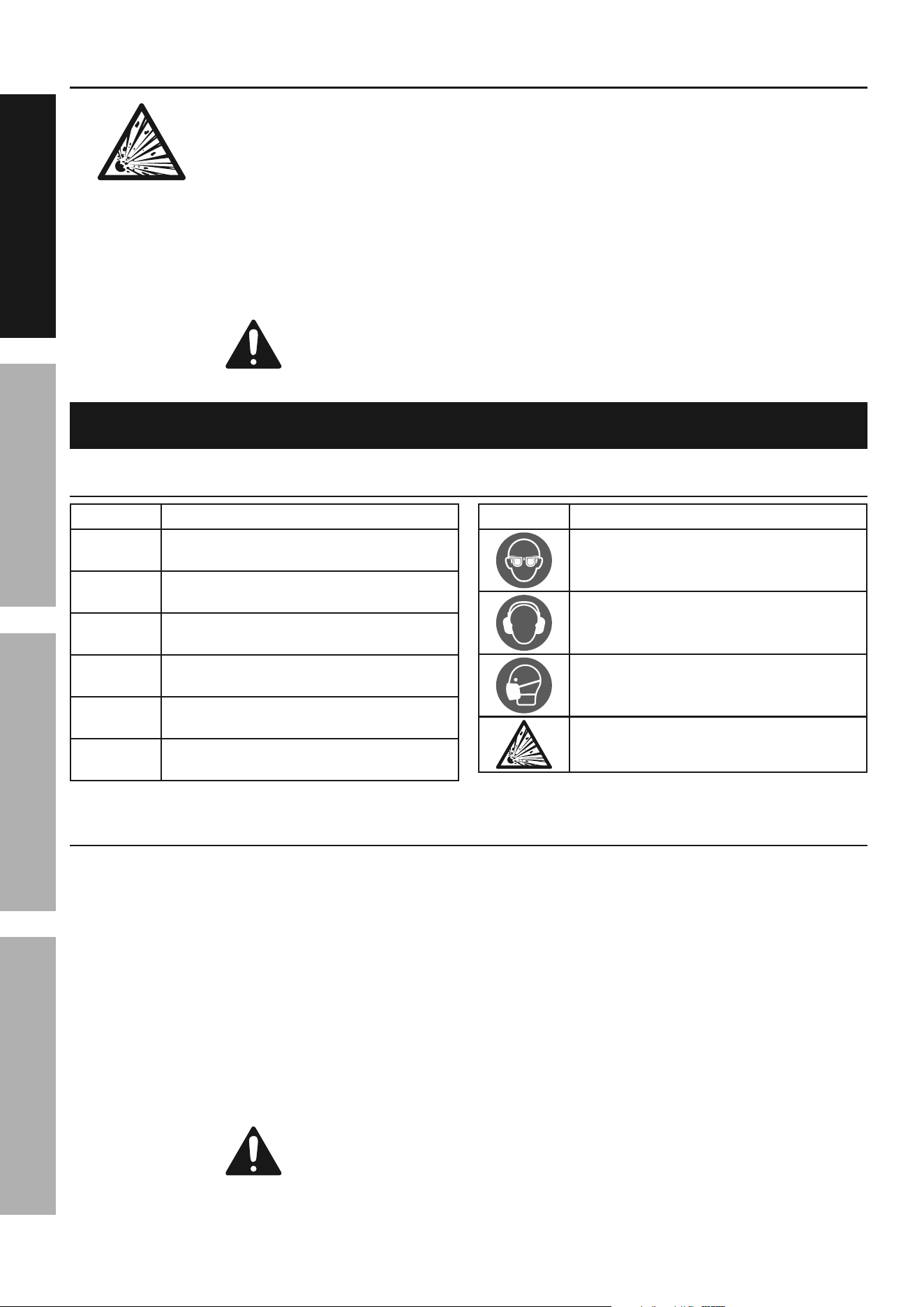
WarninG SyMBOLS anD DEFinitiOnS
This is the safety alert symbol. It is used to alert you to potential
personal injury hazards. Obey all safety messages that
follow this symbol to avoid possible injury or death.
Indicates a hazardous situation which, if not avoided,
will result in death or serious injury.
Indicates a hazardous situation which, if not avoided,
could result in death or serious injury.
Indicates a hazardous situation which, if not avoided,
could result in minor or moderate injury.
Addresses practices not related to personal injury.
iMpOrtant SaFEty inStructiOnS
inStructiOnS pErtaininG tO a riSK OF FirE,
ELEctric SHOcK, Or inJury tO pErSOnS
WarninG – When using tools, basic precautions should always be followed, including the following:
General
to reduce the risks of electric shock, fire, and injury to persons,
read all the instructions before using the tool.
Work area
1. Keep the work area clean and well lighted.
Cluttered benches and dark areas increase the
risks of electric shock, fire, and injury to persons.
2. Do not operate the tool in explosive
atmospheres, such as in the presence
of flammable liquids, gases, or dust.
The tool is able to create sparks resulting
in the ignition of the dust or fumes.
3. Keep bystanders, children, and visitors away
while operating the tool. Distractions are
able to result in the loss of control of the tool.

Page 3For technical questions, please call 1-888-866-5797.Item 58644
SaFEtyOpEratiOnMaintEnancE SEtup
personal Safety
1. Stay alert. Watch what you are doing and
use common sense when operating the tool.
Do not use the tool while tired or under the
influence of drugs, alcohol, or medication.
A moment of inattention while operating the
tool increases the risk of injury to persons.
2. Dress properly. Do not wear loose
clothing or jewelry. contain long hair.
Keep hair, clothing, and gloves away from
moving parts. Loose clothes, jewelry, or long
hair increases the risk of injury to persons as
a result of being caught in moving parts.
3. avoid unintentional starting. Be sure the switch
is off before connecting to the air supply.
Do not carry the tool with your finger on the switch or
connect the tool to the air supply with the switch on.
4. remove adjusting keys and wrenches
before turning the tool on. A wrench or a
key that is left attached to a rotating part of the
tool increases the risk of personal injury.
5. Do not overreach.
Keep proper footing and balance at all times.
Proper footing and balance enables better
control of the tool in unexpected situations.
6. use safety equipment.
A dust mask, non-skid safety shoes
and a hard hat must be used for the
applicable conditions.
7. always wear eye protection.
Wear ANSI-approved safety goggles.
8. always wear hearing protection
when using the tool.
Prolonged exposure to high intensity
noise is able to cause hearing loss.
9. risk of Electric Shock. this tool is not
provided with an insulated gripping surface.
Contact with a ″live″ wire will also make exposed
metal parts of the tool ″live″ and shock the operator.
10. avoid body contact with grounded
surfaces such as pipes, radiators, ranges
and refrigerators. There is an increased risk
of electric shock if your body is grounded.
11. Explore the workpiece to avoid contact
with hidden wiring. Thoroughly investigate
the workpiece for possible hidden wiring
before performing work. Contact with
live wiring will shock the operator.
tool use and care
1. Use clamps or another practical way to secure
and support the workpiece to a stable platform.
Holding the work by hand or against the body is
unstable and is able to lead to loss of control.
2. Do not force the tool. Use the correct tool for the
application. The correct tool will do the job better
and safer at the rate for which the tool is designed.
3. Do not use the tool if the switch does
not turn the tool on or off. Any tool that
cannot be controlled with the switch is
dangerous and must be repaired.
4. Disconnect the tool from the air source
before making any adjustments, changing
accessories, or storing the tool. Such preventive
safety measures reduce the risk of starting the
tool unintentionally. Turn off and detach the air
supply, safely discharge any residual air pressure,
and release the throttle and/or turn the switch to
its off position before leaving the work area.
5. Store the tool when it is idle out of reach
of children and other untrained persons.
A tool is dangerous in the hands of untrained users.
6. Maintain the tool with care. Keep a cutting
tool sharp and clean. A properly maintained
tool, with sharp cutting edges reduces the
risk of binding and is easier to control.
7. check for misalignment or binding of moving
parts, breakage of parts, and any other condition
that affects the tool's operation. If damaged,
have the tool serviced before using. Many accidents
are caused by poorly maintained tools.
There is a risk of bursting if the tool is damaged.
8. use only accessories that are identified by the
manufacturer for the specific tool model. Use of
an accessory not intended for use with the specific
tool model, increases the risk of injury to persons.
Service
1. Tool service must be performed only
by qualified repair personnel.
2. When servicing a tool, use only identical
replacement parts. use only authorized parts.
3. use only the lubricants supplied with the
tool or specified by the manufacturer.
Page 4 For technical questions, please call 1-888-866-5797. Item 58644
SaFEty OpEratiOn MaintEnancESEtup
air Source
1. never connect to an air source that
is capable of exceeding 200 psi.
Over pressurizing the tool may cause
bursting, abnormal operation,
breakage of the tool or serious injury
to persons. Use only clean, dry, regulated
compressed air at the rated pressure or within the
rated pressure range as marked on the tool.
Always verify prior to using the tool that the air
source has been adjusted to the rated air pressure
or within the rated air-pressure range.
2. Never use oxygen, carbon dioxide, combustible
gases or any bottled gas as an air source
for the tool. Such gases are capable of
explosion and serious injury to persons.
SaVE tHESE inStructiOnS.
Symbols and Specific Safety instructions
Symbol Definitions
Symbol property or statement
pSi
Pounds per square inch of pressure
BpM
Blows per minute
cFM
Cubic Feet per Minute flow
ScFM
Cubic Feet per Minute flow
at standard conditions
npt
National pipe thread, tapered
npS
National pipe thread, straight
Symbol property or statement
WARNING marking
concerning Risk of Eye Injury.
Wear ANSI-approved eye protection.
WARNING marking concerning Risk of
Hearing Loss. Wear hearing protection.
WARNING marking concerning
Risk of Respiratory Injury. Wear
NIOSH-approved dust mask/respirator.
WARNING marking concerning
Risk of Explosion.
Specific Safety instructions
1. Attach the Pin Cap to the Riveter before use.
2. The warnings and precautions discussed in this
manual cannot cover all possible conditions and
situations that may occur. It must be understood
by the operator that common sense and caution
are factors which cannot be built into this
product, but must be supplied by the operator.
3. Only use with accessories rated to handle the
forces exerted by this tool during operation.
Other accessories not designed for the forces
generated may break and forcefully launch pieces.
4. Attach all accessories properly to the tool before
connecting the air supply. A loose accessory
may detach or break during operation.
5. Obey the manual for the air compressor
used to power this tool.
6. Install an in-line shutoff valve to allow
immediate control over the air supply in an
emergency, even if a hose is ruptured.
7. Do not lay the tool down until it has come to
a complete stop. Moving parts can grab the
surface and pull the tool out of your control.
SaVE tHESE inStructiOnS.
Page 5For technical questions, please call 1-888-866-5797.Item 58644
SaFEtyOpEratiOnMaintEnancE SEtup
Functional Description
Specifications
Working Air Pressure 90 PSI
Maximum Air Pressure 120 PSI
Air Inlet 1/4″ NPT
Maximum Air Consumption 18 SCFM (2.5 CFM
@
90 PSI)*
Rivet Pin Capacity
1/8″, 5/32″, 3/16″, 1/4″
(Nosepiece change needed)
*Assumes 6 rivets per minute.
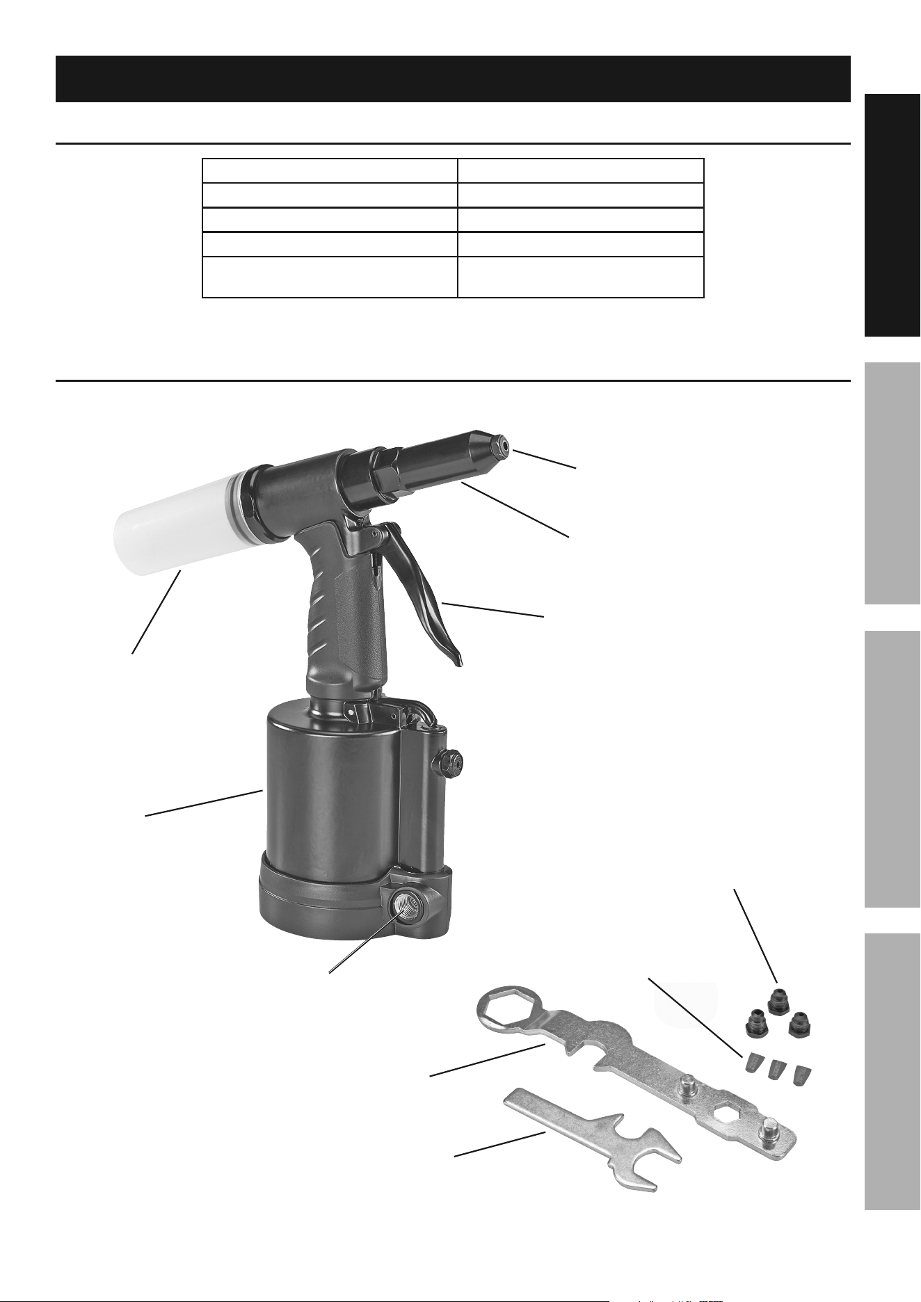
components and controls
nosepiece
pin cap
trigger
air inlet
Outer
cylinder
air
cylinder
Wrench
combination
Wrench/Gauge
additional
nosepieces
replacement
Jaw Set

Page 6 For technical questions, please call 1-888-866-5797. Item 58644
SaFEty OpEratiOn MaintEnancESEtup
initial tool Set up/assembly
read the EntirE iMpOrtant SaFEty inFOrMatiOn section at the beginning of this
manual including all text under subheadings therein before set up or use of this product.
note: For additional information regarding the parts listed in the following pages,
refer to the Assembly Diagram near the end of this manual.
note: This air tool may be shipped with a protective plug covering the air inlet. Remove this plug before set up.
air Supply
tO prEVEnt SEriOuS inJury FrOM EXpLOSiOn:
use only clean, dry, regulated, compressed air to power this tool.
Do not use oxygen, carbon dioxide, combustible gases,
or any other bottled gas as a power source for this tool.
1. Incorporate a filter, regulator with pressure gauge,
oiler, in-line shutoff valve, and quick coupler for
best service, as shown on Figure A on page 7
and Figure B on page 8. an in-line shutoff
ball valve is an important safety device because
it controls the air supply even if the air hose
is ruptured. the shutoff valve should be a
ball valve because it can be closed quickly.
note: If an automatic oiler system is not used,
add a few drops of Pneumatic Tool Oil to the airline
connection before operation. Add a few more drops
after each hour of continual use.
2. Attach an air hose to the compressor's air outlet.
Connect the air hose to the air inlet of the tool.
Other components, such as a coupler plug
and quick coupler, will make operation
more efficient, but are not required.
WarninG! tO prEVEnt SEriOuS inJury
FrOM acciDEntaL OpEratiOn:
Do not install a female quick coupler on the tool.
Such a coupler contains an air valve that will
allow the air tool to retain pressure and operate
accidentally after the air supply is disconnected.
note: Air flow, and therefore tool performance,
can be hindered by undersized air supply components.
The air hose must be long enough to reach
the work area with enough extra length to
allow free movement while working.
3. Turn the tool's throttle or switch to the off position;
refer to Operation section for description of controls.
4. Close the in-line shutoff valve between
the compressor and the tool.
5. Turn on the air compressor according to
the manufacturer's directions and allow it
to build up pressure until it cycles off.
6. Adjust the air compressor's output regulator
so that the air output is enough to properly
power the tool, but the output will not exceed
the tool's maximum air pressure at any time.
Adjust the pressure gradually, while checking the
air output gauge to set the right pressure range.
7. Inspect the air connections for leaks.
Repair any leaks found.
8. If the tool will not be used at this time, turn off
and detach the air supply, safely discharge
any residual air pressure, and release
the throttle and/or turn the switch to its off
position to prevent accidental operation.
9. Residual air pressure should not be present
after the tool is disconnected from the air
supply. However, it is a good safety measure
to attempt to discharge the tool in a safe
fashion after disconnecting to ensure that the
tool is disconnected and not powered.
Page 7For technical questions, please call 1-888-866-5797.Item 58644
SaFEtyOpEratiOnMaintEnancE SEtup
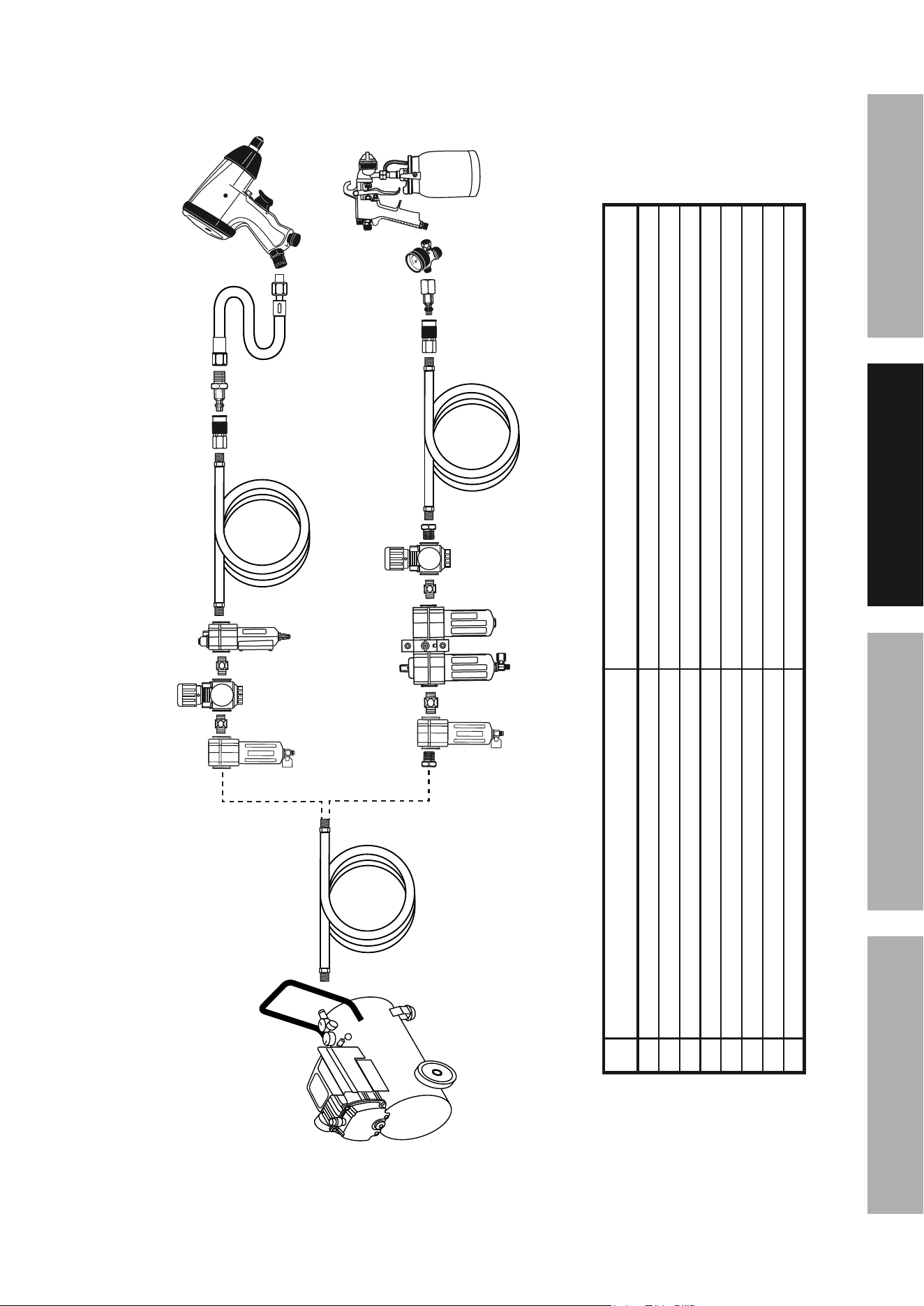
Figure a: portable air Supply Setup
G
A
E
E
H
F
B
Non-lubricated
Tools
Lubricated
Tools
A
B
C
C
D
A
Description Function
A Air Hose Connects air to tool
B Filter Prevents dirt and condensation from damaging tool or workpiece
C Regulator Adjusts air pressure to tool
D Lubricator (optional) For air tool lubrication
E Coupler and Plug Provides quick connection and release
F Leader Hose (optional) Increases coupler life
G Air Cleaner / Dryer (optional) Prevents water vapor from damaging workpiece
H Air Adjusting Valve (optional) For fine tuning airflow at tool
Page 8 For technical questions, please call 1-888-866-5797. Item 58644
SaFEty OpEratiOn MaintEnancESEtup
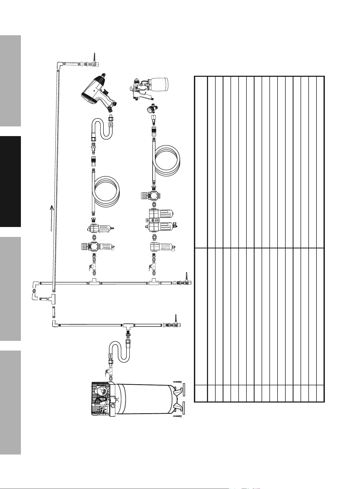
Figure B: Stationary air Supply Setup
N
L
L O
M
C
C
Non-lubricated Tools
Lubricated
Tools
H
I
I
J
J
K
H
F
G
E
Slope
F
F
B
B
A
A
C
D
Description Function
A Vibration Pads For noise and vibration reduction
B Anchor Bolts Secures air compressor in place
C Ball Valve Isolates sections of system for maintenance
D Isolation Hose For vibration reduction
E Main Air Line - 3/4″ minimum recommended Distributes air to branch lines
F Ball Valve To drain moisture from system
G Branch Air Line -1/2″ minimum recommended Brings air to point of use
H Air Hose Connects air to tool
I Filter Prevents dirt and condensation from damaging tool or workpiece
J Regulator Adjusts air pressure to tool
K Lubricator (optional) For air tool lubrication
L Coupler and Plug Provides quick connection and release
M Leader Hose (optional) Increases coupler life
N Air Cleaner / Dryer (optional) Prevents water vapor from damaging workpiece
O Air Adjusting Valve (optional) For fine tuning airflow at tool

Page 9For technical questions, please call 1-888-866-5797.Item 58644
SaFEtyOpEratiOnMaintEnancE SEtup
Operating instructions
read the EntirE iMpOrtant SaFEty inFOrMatiOn section at the beginning of this
manual including all text under subheadings therein before set up or use of this product.
inspect tool before use, looking for damaged, loose, and missing parts.
if any problems are found, do not use tool until repaired.
tool Set up
tO prEVEnt SEriOuS inJury FrOM acciDEntaL OpEratiOn:
turn off the tool, detach the air supply, safely discharge any residual air pressure in the tool, and
release the trigger before performing any inspection, maintenance, or cleaning procedures.
tO prEVEnt SEriOuS inJury:
Do not adjust or tamper with any control or component in a way not specifically explained within this
manual. improper adjustment can result in tool failure or other serious hazards.
nosepieces
1. The Riveter comes with four Nosepieces:
(1A = 1/4″), (1B = 3/16″), (1C = 5/32″), (1D = 1/8″).
Nosepieces are stored in the Air Cylinder Cap.
2. Use the 3-Way Wrench to remove the old
nosepiece and install the new one. Tighten
the new nosepiece in place before use.
Workpiece and Work area Set up
1. Designate a work area that is clean and well-lit.
The work area must not allow access by children
or pets to prevent distraction and injury.
2. Route the air hose along a safe route to reach
the work area without creating a tripping hazard
or exposing the air hose to possible damage.
The air hose must be long enough to reach
the work area with enough extra length to
allow free movement while working.
3. Secure loose workpieces using a vise or clamps
(not included) to prevent movement while working.
4. There must not be hazardous objects
(such as utility lines or foreign objects) nearby
that will present a hazard while working.

Page 10 For technical questions, please call 1-888-866-5797. Item 58644
SaFEty OpEratiOn MaintEnancESEtup
General Operating instructions
1. If an automatic oiler is not used, add a few
drops of Pneumatic Tool Oil to the airline
connection before use. Add a few drops
more after each hour of continual use.
2. Affix the Pin Cap securely to the Riveter Housing.
3. Depending on the size of rivet’s pin used, attach
the corresponding Nosepiece size (1/8″, 5/32″,
3/16″, or 1/4″) using the included Wrench.
iMpOrtant: When drilling rivet holes in a
workpiece, use the same diameter drill bit as
the outer diameter of rivet being used.
WarninG! tO prEVEnt SEriOuS
inJury: Verify that work surface has no
hidden utility lines before drilling.
4. Attach an air hose to the Air Inlet.
5. Turn on the air compressor, and set its
regulator to the needed pressure.
WarninG! tO prEVEnt inJury FrOM
tOOL Or accESSOry FaiLurE:
Do not exceed the tool’s
maximum air pressure rating.
6. Insert the small end of a rivet fully through
the Nosepiece. WarninG! tO prEVEnt
SEriOuS inJury: Keep clear of the
trigger when inserting rivets.
7. Insert the rivet through the predrilled
hole in the workpiece.
8. Hold the Riveter firmly against the workpiece
with both hands and squeeze the Trigger to
activate the Riveter, then release the Trigger.
9. Check to be sure the rivet looks solid and
securely locks the workpiece together.
• If the installed rivet is too loose then the
workpiece sections will move and not be locked
together. This indicates the rivet pin was not
adequately pulled through the workpiece. Either
the wrong size rivet was used or Riveter’s Jaw
Case is too loose and not gripping the rivet pin
well enough to pull it fully through the workpiece.
• A concave, deformed or broken rivet head
indicates the rivet pin was pulled too far into
the workpiece. Either the wrong size rivet was
used or Riveter’s Jaw Case is too tight and not
properly releasing the rivet pin during installation.
10. If the tool requires more force to accomplish
the task, verify that the tool receives sufficient,
unobstructed airflow (CFM) and increase the
pressure (PSI) output of the regulator up to the
maximum air pressure rating of this tool.
WarninG! tO prEVEnt SEriOuS inJury FrOM
tOOL Or accESSOry FaiLurE:
Do not exceed the tool’s
maximum air pressure rating.
If the tool still does not have sufficient force
at maximum pressure and sufficient airflow,
then a larger tool may be required.
11. To prevent accidents, turn off the tool, detach
the air supply, safely discharge any residual
air pressure in the tool, and release the trigger
after use. Clean external surfaces of the tool with
clean, dry cloth, and apply a thin coat of tool oil.
Then store the tool indoors out of children’s reach.
Page 11For technical questions, please call 1-888-866-5797.Item 58644
SaFEtyOpEratiOnMaintEnancE SEtup
user-Maintenance instructions
procedures not specifically explained in this manual must
be performed only by a qualified technician.
tO prEVEnt SEriOuS inJury FrOM acciDEntaL OpEratiOn:
turn off the tool, detach the air supply, safely discharge any residual air pressure in the tool, and
release the trigger before performing any inspection, maintenance, or cleaning procedures.
tO prEVEnt SEriOuS inJury FrOM tOOL FaiLurE:
Do not use damaged equipment. if abnormal noise, vibration,
or leaking air occurs, have the problem corrected before further use.
tO prEVEnt SErOuS inJury FrOM EXpLOSiOn:
Lubricate the tool only with specified lubricants. Lubricate the air inlet using only
pneumatic tool oil. Other lubricants may damage the mechanism and may be
highly flammable, causing an explosion.
cleaning, Maintenance, and Lubrication
note: These procedures are in addition to the regular checks and maintenance
explained as part of the regular operation of the air-operated tool.
1. BEFOrE EacH uSE, inspect the general
condition of the tool. Check for:
• loose hardware or housing
• misalignment or binding of moving parts
• cracked or broken parts
• any other condition that may
affect its safe operation.
2. aFtEr EVEry uSE, wipe exterior with a clean,
damp cloth using a mild detergent or isopropyl
alcohol. Do not immerse the tool in liquids.
3. Daily - air Supply Maintenance:
Every day, maintain the air supply according
to the component manufacturers' instructions.
Maintain the lubricator's oil level.
Drain the moisture filter regularly.
Performing routine air supply maintenance
will allow the tool to operate more safely
and will also reduce wear on the tool.
4. Quarterly (every 3 months) –
tool Disassembly, cleaning, and inspection:
Have the internal mechanism cleaned, inspected,
and lubricated by a qualified technician.
Jaw cleaning and replacement
1. Unscrew and remove the Outer
Cylinder using the Wrench.
2. Unscrew and remove the Jaw Case from the
Jaw Cylinder. use care as there is a Jaw
pusher and Jaw pusher Spring behind
the Jaw case which may fly out.
Outer cylinder
Jaw
case
Jaws
Jaw
pusher
Jaw pusher
Spring
Jaw
cylinder
nosepiece
3. Remove the Jaw Pusher and
Jaws from the Jaw Case.
4. To clean the Jaws, use a steel brush and
isopropyl alcohol (sold separately). Apply
a light coat of machine oil to the Jaws and
insert them back into the Jaw Case.
5. To replace the Jaws, insert the new
set of Jaws into the Jaw Case.
6. Place the Jaw Pusher in between the
Jaws, pushing them slightly apart.
7. Screw the Jaw Case onto the Jaw Cylinder.
Page 12 For technical questions, please call 1-888-866-5797. Item 58644
SaFEty OpEratiOn MaintEnancESEtup
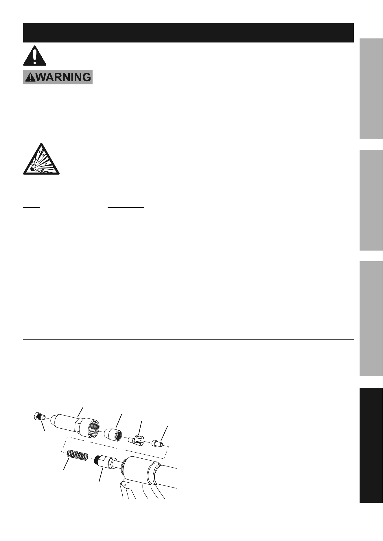
check Jaw case alignment
1. With the Combination Wrench / Gauge at a slight
incline, rest the back of the Wrench / Gauge
on the front of the Housing Threads.
2. The front of the Wrench / Gauge should be in
alignment with the front edge of the Jaw Case.
3. If the Jaw Case is out of alignment,
correct by threading the Jaw Case
in or out on the Jaw Cylinder.
4. Confirm Lock Nut is tight against Jaw Cylinder.
nOtE: Use the included Combination Wrench / Gauge
as a general guideline only. Jaw case tightness must
be fine-tuned to the application, rivet supplier, etc.
5. Replace the Outer Cylinder and
tighten using the Wrench.
Wrench / Gauge
Housing
threads
Jaw case Jaw
cylinder
Lock
nut
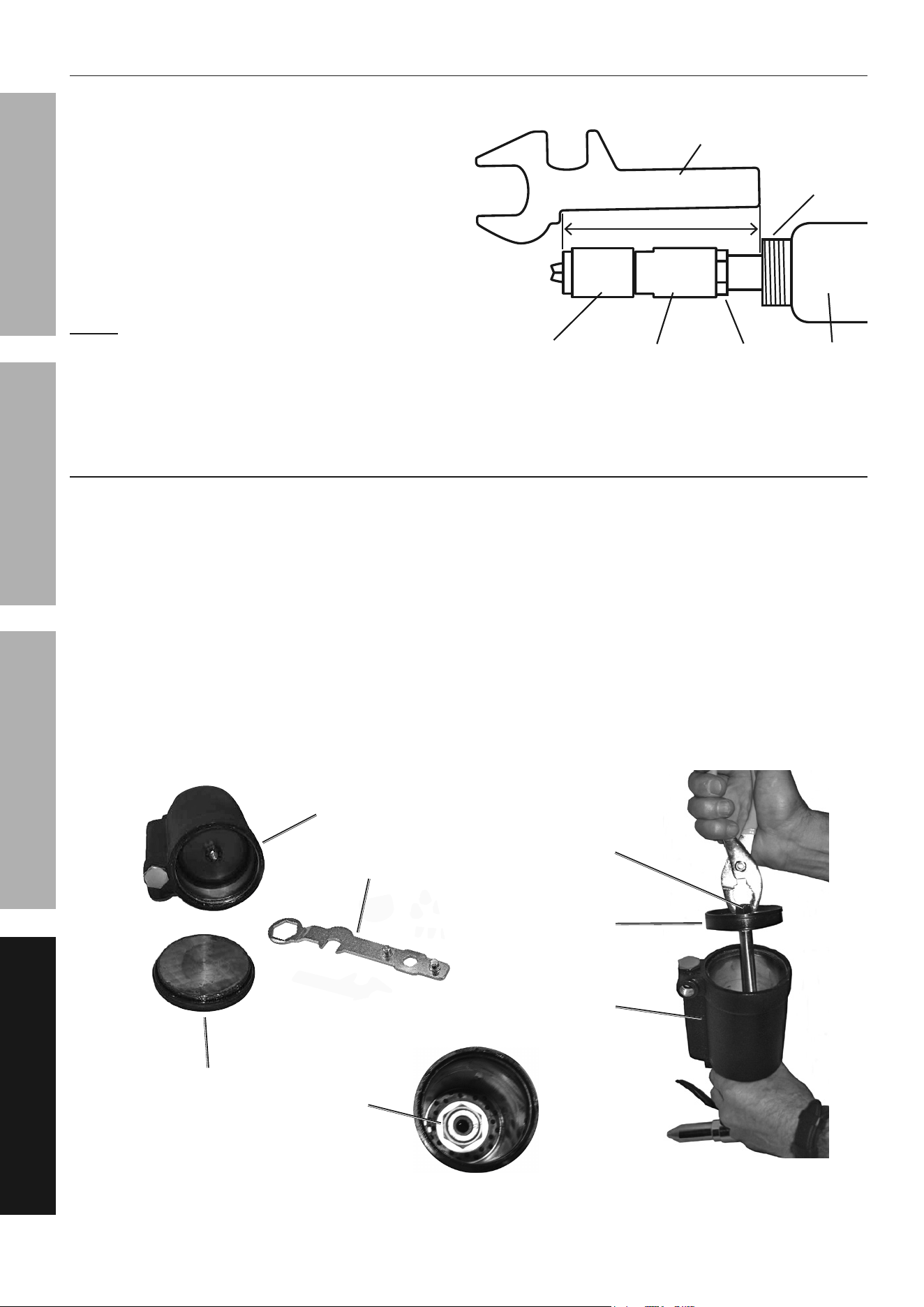
priming
1. Unscrew and remove the Outer
Cylinder using the Wrench.
1. Remove the Base Cover and use the 3-Way
Wrench to unscrew and remove the Air
Cylinder Cap from the bottom of the Riveter.
2. Use a pair of pliers (not included) to grasp the
Piston Head Lock Nut and remove the Piston
Head Assembly from the Air Cylinder.
3. Hold the Air Cylinder upside down, and pour
in hydraulic fluid (not included). The fill level
should only reach the top of the Housing,
where the Lock Nut attaches to the Housing.
4. Apply silicone-based grease (not included)
to the inner wall of the Air Cylinder
and the Piston Head O-Ring.
5. Insert the Piston Head back into the Air Cylinder.
6. Use the Wrench to firmly screw the Air
Cylinder Cap back onto the Air Cylinder.
7. Replace the Base Cover.
3-Way Wrench
Bottom of
air cylinder
air cylinder
Lock nut
piston Head
air cylinder
cap
piston Head
Lock nut
Page 13For technical questions, please call 1-888-866-5797.Item 58644
SaFEtyOpEratiOnMaintEnancE SEtup
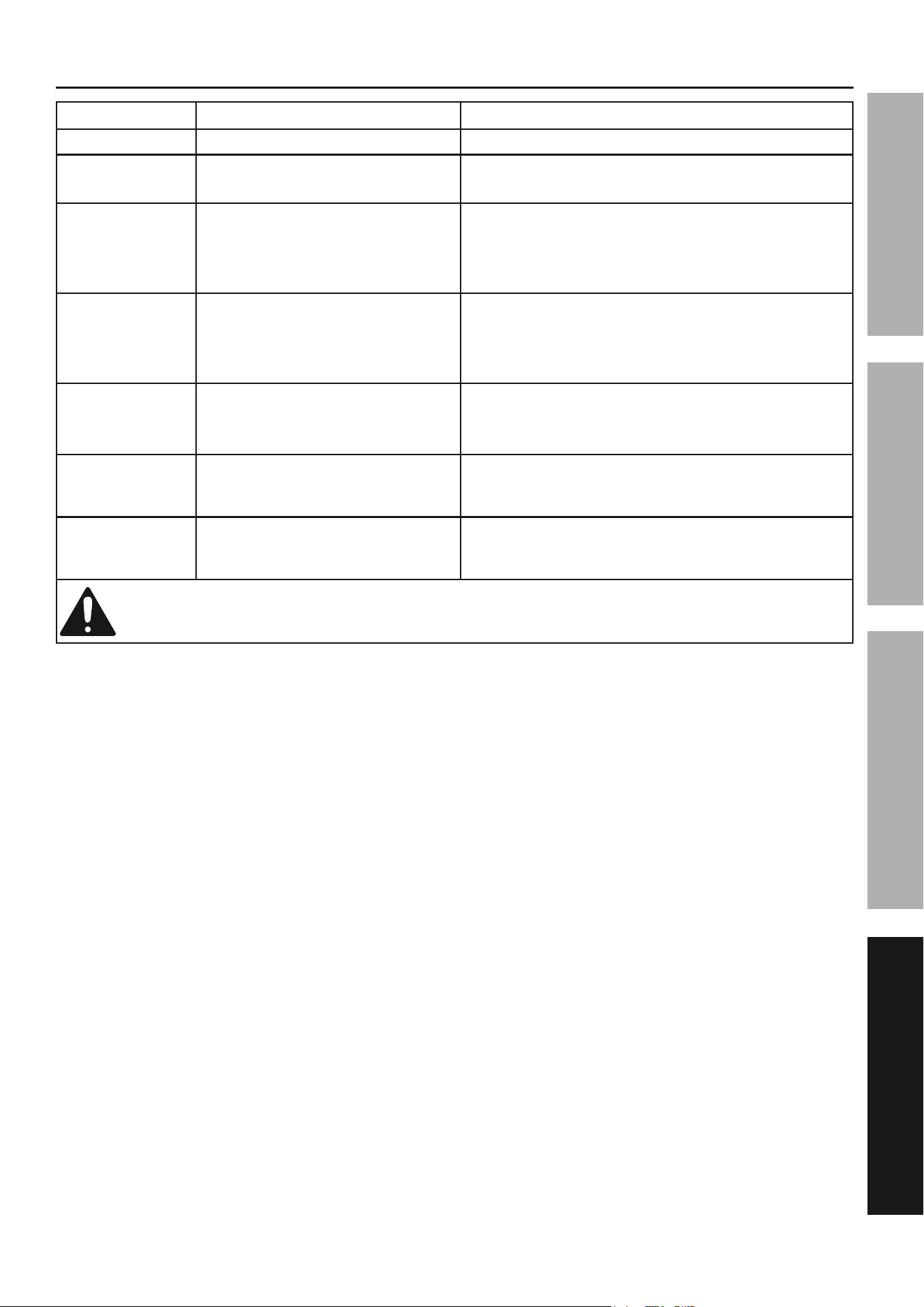
troubleshooting
problem possible causes Likely Solutions
Jaws slipping. Worn or damaged Jaws. Replace Jaws.
Jaws will
not open.
1. Loose Nosepiece.
2. Dirty Jaws.
1. Tighten Nosepiece.
2. Clean Jaws.
Stroke is
too short.
1. Rivet pin not properly
inserted into Riveter.
2. Low hydraulic fluid.
3. Rivet wrong size.
1. Fully insert pin.
2. Prime Riveter – see page 12.
3. Use proper rivet length.
Weak pulling
action.
1. Low air pressure.
2. Broken/inadequate
air compressor.
3. Low hydraulic fluid.
1. Check regulator.
2. Have compressor serviced by a qualified technician/
upgrade to compressor of sufficient capability.
3. Prime Riveter – see page 12.
Leaking air. 1. Poor hose connections.
2. Damaged O-Ring.
3. Dirty Air Valve or airline inlet.
1. Reconnect using pipe thread seal tape.
2. Replace O-Ring.
3. Clean and lubricate with pneumatic tool oil.
Workpiece not
tightly held
together by rivet.
Rivet pin not pulled far enough
through workpiece.
Tighten Riveter’s Jaw Case and use proper size rivet.
Rivet head
deformed in
workpiece.
Rivet pin not properly released
during installation.
Loosen Riveter’s Jaw Case and use proper size rivet.
Follow all safety precautions whenever diagnosing or servicing the tool.
Disconnect air supply before service.
Page 14 For technical questions, please call 1-888-866-5797. Item 58644
SaFEty OpEratiOn MaintEnancESEtup
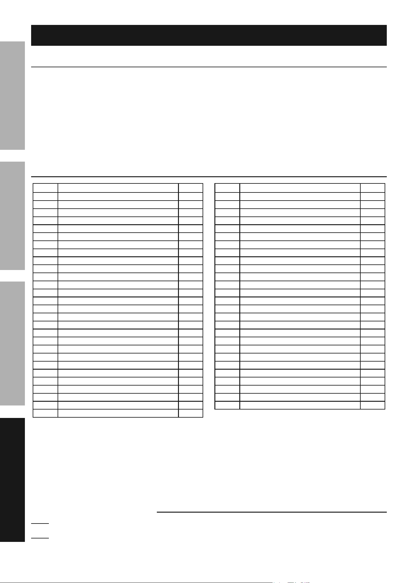
part Description Qty
1A 1/4″ Nosepiece 1
1B 3/16″ Nosepiece 1
1C 5/32″ Nosepiece 1
1D 1/8″ Nosepiece 1
2 Outer Cylinder 1
3 Jaw Case 1
4 Jaws 2 Sets
5 Jaw Pusher 1
6 Jaw Pusher Spring 1
7 Jaw Cylinder 1
8 Lock Nut 1
9 Hydraulic Piston 1
10 Ring 1
11 Housing 1
12 Restore Spring 1
13 Ring 1
14 Restore Spring 1
15 Pin Cap 1
16 Airtight Lid 1
17 Silencer 1
18 Lock Nut 1
19 Air Cylinder 1
20 Piston Stem 1
21 Cushion 1
22 Piston Head 1
23 Piston Head Lock Nut 1
24 Air Cylinder Cap 1
25 Trigger 1
part Description Qty
26 Connecting Rod 1
27 Pressing Plate 1
28 Air Valve 1
29 Valve Spring 1
30 Copper Washer 1
31 Valve 1
32 Spring 1
33 Nut 1
34 Base Cover 1
35 Filter 1
A09 Handle Sleeve 1
B01 O-Ring 2
B02 O-Ring 1
B03 O-Ring 1
B04 O-Ring 2
B05 O-Ring 1
B06 Spring Pin 1
B07 Spring Pin 2
B08 Pin 1
B09 Spring Pin 1
B10 O-Ring 1
B11 O-Ring 1
B12 O-Ring 1
B13 O-Ring 1
B14 O-Ring 1
C02 3-Way Wrench 1
C03 Combination Wrench / Gauge 1
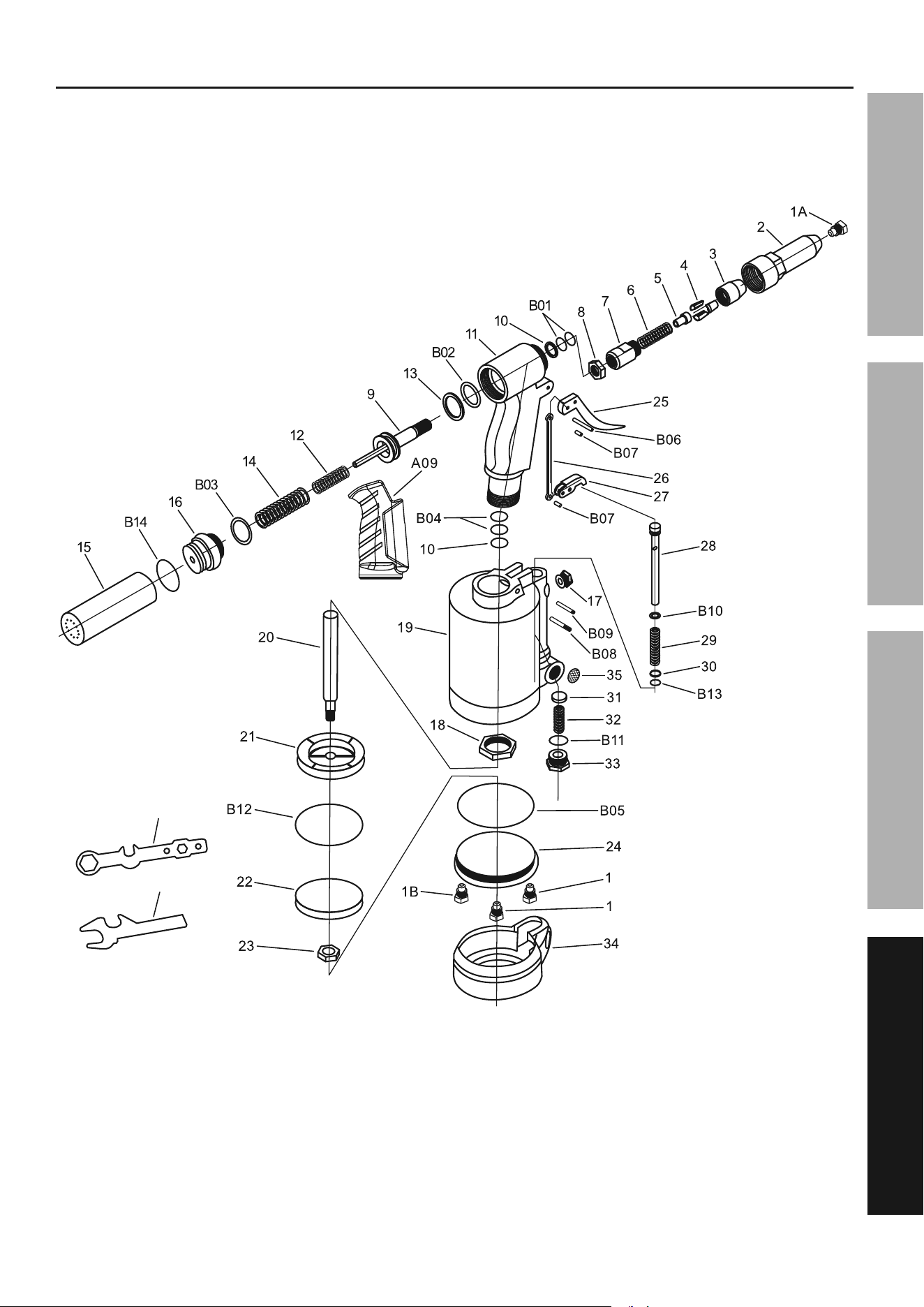
parts List and Diagram
pLEaSE rEaD tHE FOLLOWinG carEFuLLy
THE MANUFACTURER AND/OR DISTRIBUTOR HAS PROVIDED THE PARTS LIST AND ASSEMBLY DIAGRAM
IN THIS MANUAL AS A REFERENCE TOOL ONLY. NEITHER THE MANUFACTURER OR DISTRIBUTOR
MAKES ANY REPRESENTATION OR WARRANTY OF ANY KIND TO THE BUYER THAT HE OR SHE IS
QUALIFIED TO MAKE ANY REPAIRS TO THE PRODUCT, OR THAT HE OR SHE IS QUALIFIED TO REPLACE
ANY PARTS OF THE PRODUCT. IN FACT, THE MANUFACTURER AND/OR DISTRIBUTOR EXPRESSLY
STATES THAT ALL REPAIRS AND PARTS REPLACEMENTS SHOULD BE UNDERTAKEN BY CERTIFIED AND
LICENSED TECHNICIANS, AND NOT BY THE BUYER. THE BUYER ASSUMES ALL RISK AND LIABILITY
ARISING OUT OF HIS OR HER REPAIRS TO THE ORIGINAL PRODUCT OR REPLACEMENT PARTS
THERETO, OR ARISING OUT OF HIS OR HER INSTALLATION OF REPLACEMENT PARTS THERETO.
parts List
record product's Serial number Here:
note: If product has no serial number, record month and year of purchase instead.
note: Some parts are listed and shown for illustration purposes only, and are not available
individually as replacement parts. Specify UPC 193175443212 when ordering parts.
Page 15For technical questions, please call 1-888-866-5797.Item 58644
SaFEtyOpEratiOnMaintEnancE SEtup
assembly Diagram
C02
C03
C
D

Limited 90 Day Warranty
Harbor Freight Tools Co. makes every effort to assure that its products meet high quality and durability standards,
and warrants to the original purchaser that this product is free from defects in materials and workmanship for the
period of 90 days from the date of purchase. This warranty does not apply to damage due directly or indirectly,
to misuse, abuse, negligence or accidents, repairs or alterations outside our facilities, criminal activity, improper
installation, normal wear and tear, or to lack of maintenance. We shall in no event be liable for death, injuries
to persons or property, or for incidental, contingent, special or consequential damages arising from the use of
our product. Some states do not allow the exclusion or limitation of incidental or consequential damages, so the
above limitation of exclusion may not apply to you. THIS WARRANTY IS EXPRESSLY IN LIEU OF ALL OTHER
WARRANTIES, EXPRESS OR IMPLIED, INCLUDING THE WARRANTIES OF MERCHANTABILITY AND FITNESS.
To take advantage of this warranty, the product or part must be returned to us with transportation charges
prepaid. Proof of purchase date and an explanation of the complaint must accompany the merchandise.
If our inspection verifies the defect, we will either repair or replace the product at our election or we may
elect to refund the purchase price if we cannot readily and quickly provide you with a replacement. We will
return repaired products at our expense, but if we determine there is no defect, or that the defect resulted
from causes not within the scope of our warranty, then you must bear the cost of returning the product.
This warranty gives you specific legal rights and you may also have other rights which vary from state to state.
26677 agoura road • calabasas, ca 91302 • 1-888-866-5797