DO NOT DISCARD – GIVE TO USER
WARNING
BEFORE USE
Study, understand and follow all instructions provided with this
product. Read these instructions carefully before installing, operating,
servicing or repairing this tool. Keep these instructions in a safe
accessible place.
INTENDED USE OF THE TOOL
WARNING
MADE IN CHINA
to Matco specifications
This tool is intended to be used to install metric M5, M6, M8 and
SAE 10-24, 1/4-20, 5/16-18 rivet nuts. Do not use this tool outside of
the designed intent. Never modify the tool for any other purpose
or use.
The manufacturer warrants this product to the original user against
defective material or workmanship for a period of 1 year from the
date of purchase.
The manufacturer reserves the right to determine whether the part
or parts failed because of defective material, workmanship or other
causes. Failures caused by accident, alteration or misuse are not
covered by this warranty.
The manufacturer, at its discretion, will repair or replace product
covered under this warranty free of charge. Repairs or replacements
of products covered under this warranty are warranted for the
remainder of the original warranty period.
The manufacturer or its authorized service representatives must
perform all warranty repairs. Any repair to the product by
unauthorized service representatives voids this warranty. The rights
under this warranty are limited to the original user and may not be
transferred to subsequent owners.
The warranty is in lieu of all other warranties, expressed or implied,
including warranties of merchantability and fitness for a particular
purpose. Some states do not allow the exclusion or limitations of
incidental or consequential damages, so the above limitations may
not apply to you.
1 YEAR LIMITED WARRANTY
Before use, check the parts diagram and part number listing on
page 4 to make sure all parts are included. If any parts are missing
or damaged, please call your distributor.
Caution: To help prevent personal injury
Use of this product can expose you to chemicals including ethylene
glycol, gasoline vapors and engine exhaust, which are known to the
State of California to cause cancer, birth defects, or reproductive
harm. For more information, visit www.P65Warnings.ca.gov.
Always wear ANSI approved safety equipment, safety glasses and
clothing when using this product. Study, understand, and follow all
instructions provided with this product. Failure to read and follow
all warnings and operating instructions may result in damages and
serious injury or death.
• Always wear ANSI approved goggles when using this product
(users and bystanders).
• Never use this tool for any application other than for which
it was designed.
• Only use accessories designed for this tool.
• Never alter or modify this tool in any way.
• Improper operation and/or maintenance of the tool, modification
of the tool or use of the tool with accessories not designed for it
could result in serious injury or death.
• Always select the correct accessories of the correct size and
design for the job that you are attempting to perform.
• Always work in a clean, safe, well-lit, organized and adequately
equipped area.
• Do not begin repairs without assurance that vehicle is in secure
position and will not move during repair.
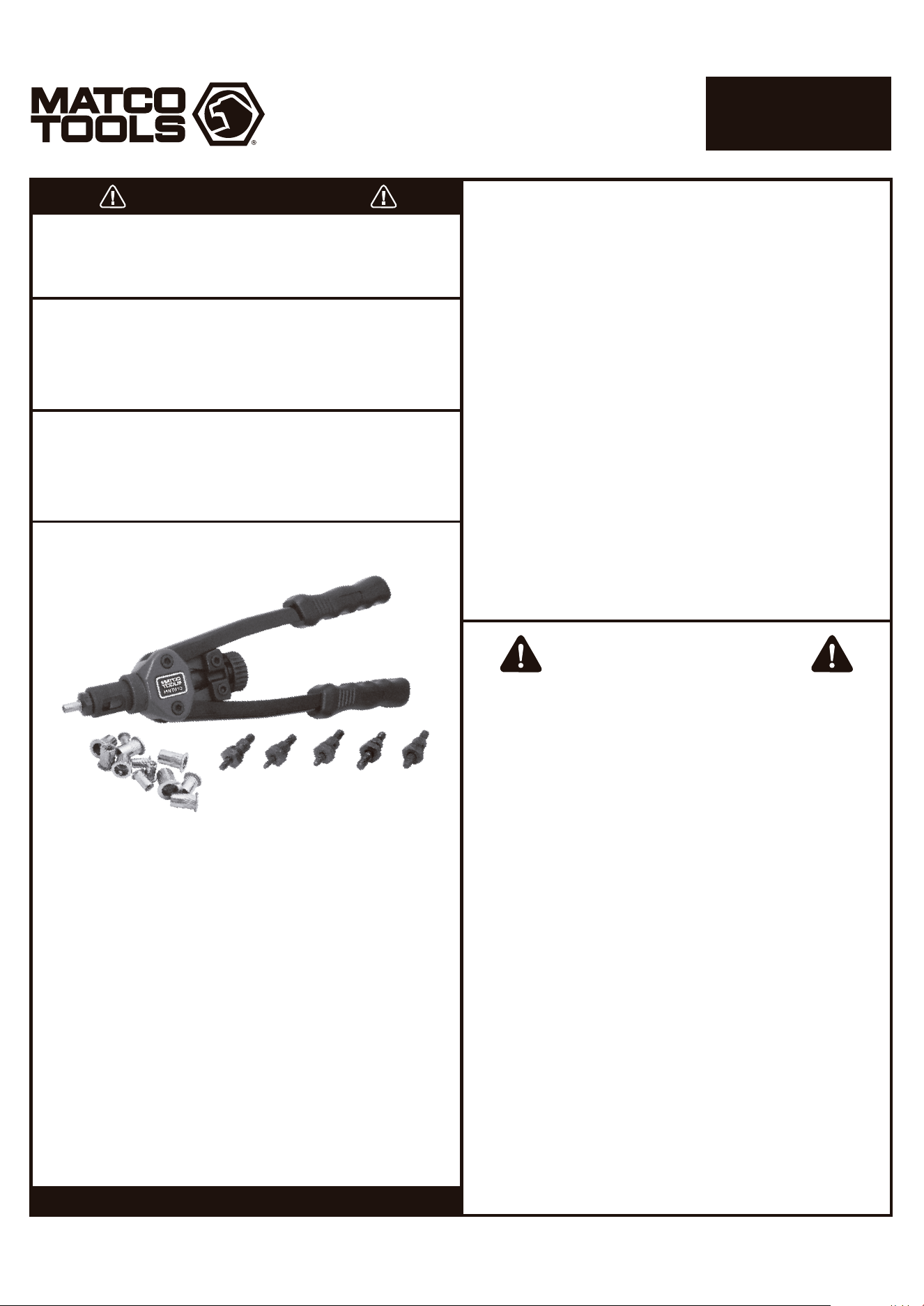
PRODUCT INFORMATION
SPECIFICATIONS
• Work faster. Change mandrel sizes by hand without wrenches
using unique quick-change design.
• Comprehensive coverage. Includes metric sizes M5, M6 & M8 and
SAE 10-24, 1/4-20 & 5/16-18 mandrels, nose pieces and 10 piece
rivet nuts each.
• Maximum strength. Patented structure outputs 30 times the
input force.
• Shorter handle with double compound hinges that maximize leverage.
• Ergonomic grip for easy operation.
Weight: 2.43 lbs. (1100g)
Length: 13" (330mm)
Max. Working Stroke: 9mm
Arm Force Multiplier: 30
Page 1
MNTS13
13" NUT/THREAD
SETTER KIT
1508128-14MA
Assembly direction
Page 2
MNTS13
13" NUT/THREAD
SETTER KIT
WARNING
Always wear ANSI approved safety goggles when using this
product (Users and Bystanders). Failure to read and follow all
warnings and operating instructions may result in damages
and serious injuries or death.
OPERATING INSTRUCTIONS
1. Choose the rivet nut size to be installed.
2. Install the correct size mandrel/nosepiece for the rivet nut to be
installed. See photos and instructions for changing the
mandrel/nosepiece and adjustment.
3. Drill a hole in the work product the same size or slightly larger
than the outside diameter of the rivet nut to be installed.
4. To install the rivet nut, open the handles outward as far as
possible and thread the rivet nut clockwise onto the mandrel until
reaching the nosepiece.
5. Insert the rivet nut fastened to the riveter into the pre-drilled hole
until flush with the work product and pull handles inward to
secure the rivet nut into the hole. If the rivet nut is loose in the
hole, open the handles outward, turn #19 knob clockwise and pull
handles inward until the rivet nut is secure in the hole. Repeat as
necessary until the rivet nut is secure in the hole. See adjustment
instructions if necessary.
6. Turn the #19 knob counterclockwise until the mandrel is removed
from the rivet nut. The rivet nut installation is complete if the rivet
nut is secure from movement in the hole.
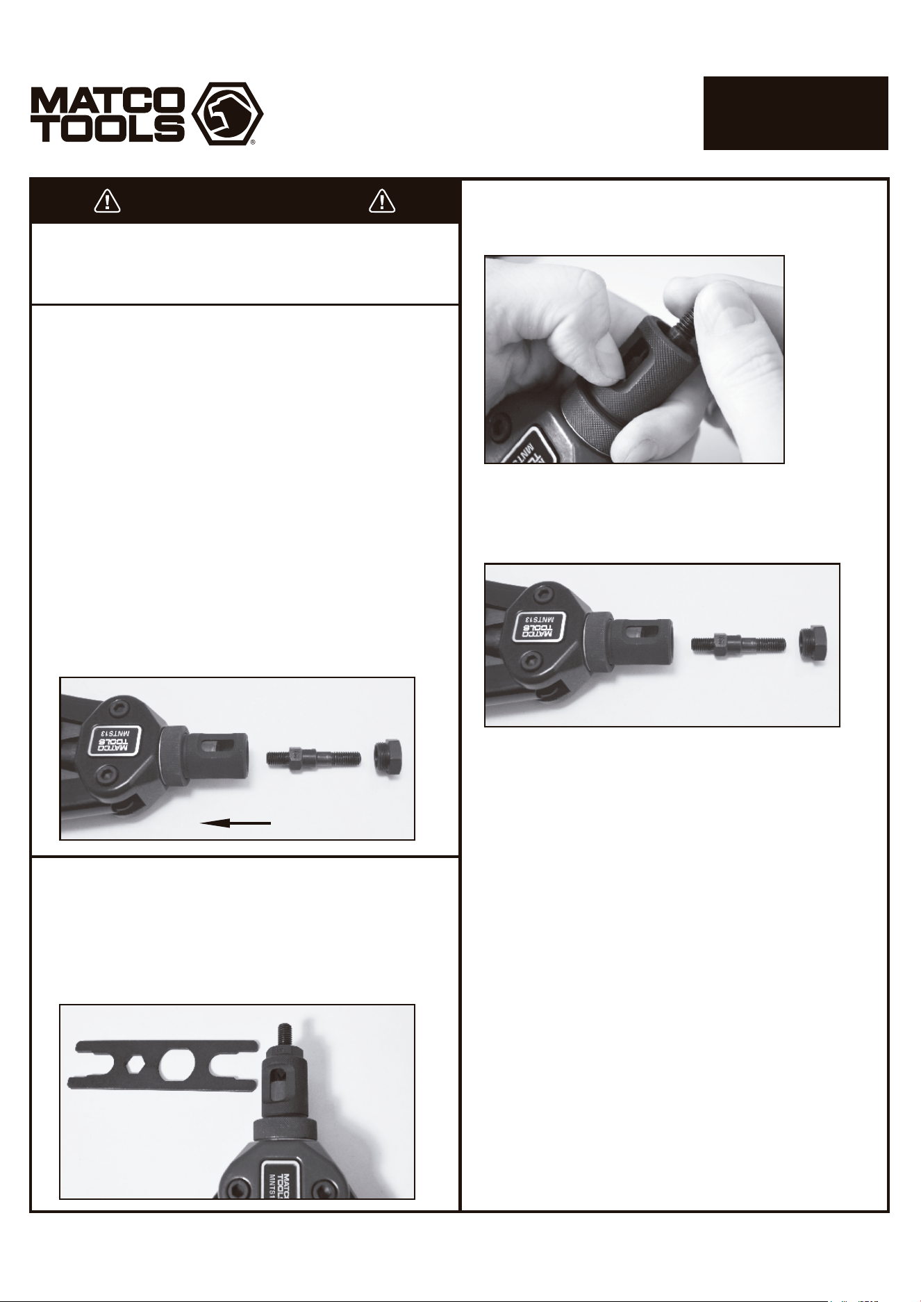
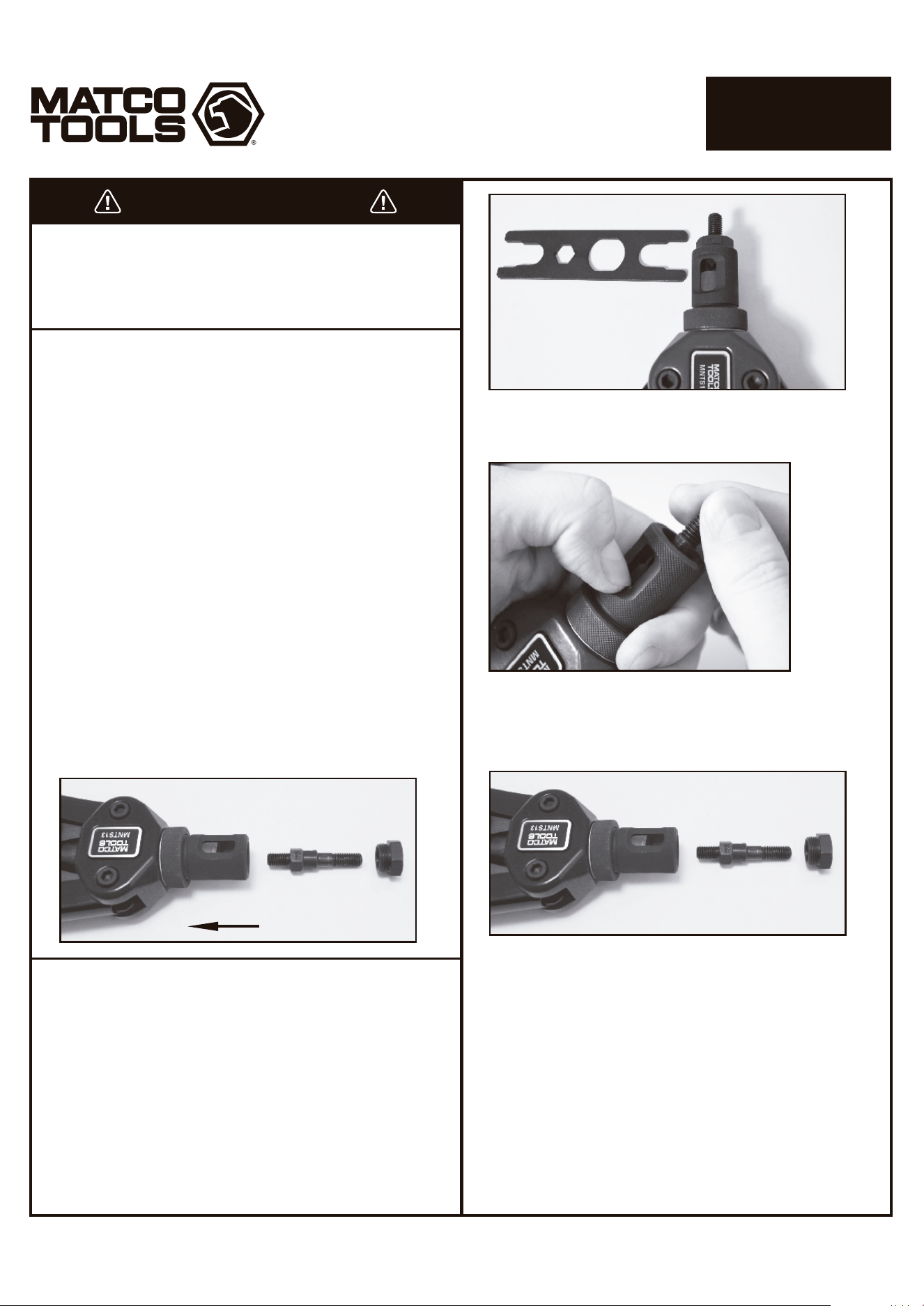
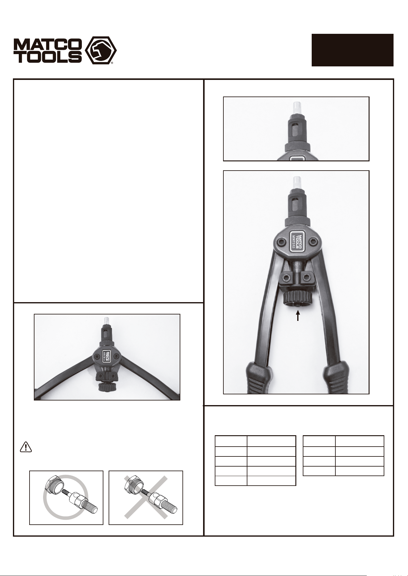
1. Remove and install the mandrel and nosepieces. Always keep
the matched mandrel/nosepiece sets together.
2. Remove nosepiece from #3 sleeve by unthreading the nose
piece counterclockwise. This can be done either by hand or with
the provided wrench if too tight to do so.
CHANGING MANDREL/
NOSEPIECE INSTRUCTIONS
3. Using your thumbnail or tool, press down to depress the #6 inner
hexagonal sleeve that sits within the #3 outer sleeve. This should
expose the lower hex portion of the mandrel.
4. Unthread the mandrel by hand to remove it from the sleeve. Once
the mandrel has been threaded out far enough to clear the #6 hex
sleeve you may release tension on this sleeve collar.
5. Choose the correct mandrel/nosepiece to be installed.
6. Thread the new mandrel into the tool by hand until it approaches
the #6 hex sleeve and fully depress this sleeve to allow the
mandrel to be threaded further until it stops. The mandrel does
not need to be torqued. Release the hex sleeve and allow it to
fully reengage the mandrel. If the mandrel and hex sleeve do not
initially align, rotate the #19 knob while holding onto the mandrel
until it clicks up and reengages.
7. Thread the matching nose piece into the #3 by hand. Torquing the
nose piece is optional.
1508128-14MA
M5
M5
M5
M6
Riveter properly prepared
for setting rivet nuts
Store matching nosepieces and mandrels
together when not in use to prevent mismatching
the sizes and for convenience.
Open handles
and thread
rivet nut
onto mandrel
Turn knob
counterclockwise
after rivet nut
setting is
complete to
remove riveter
from the rivet nut
13" NUT/THREAD
SETTER KIT
Page 3
MNTS13
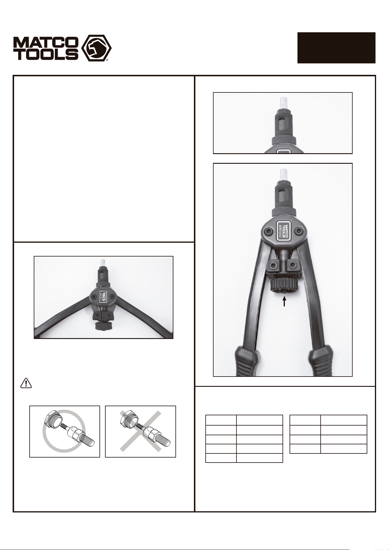
ADJUSTMENT INSTRUCTIONS
1. Proper adjustment of the riveter is necessary for efficient and easy
operation.
2. The adjustment of the riveter will vary, depending on the size and
type of rivet nut being used and the hole size.
3. Adjust the riveter by opening the handles outward as far as
possible loosening the #4 adjusting nut and turning the #3 outer
sleeve clockwise to increase the number of threads on the mandrel
protruding beyond the nosepiece for larger rivet nuts, and by
turning the #3 outer sleeve counterclockwise for smaller rivet nuts.
Once adjustment is set, tighten the #4 adjusting nut by hand. Fine
adjustment can be made by turning the rivet nut on the mandrel to
position the rivet nut closer or further away from the nosepiece, as
long as the mandrel is threaded all the way through the rivet nut.
4. Always ensure that the mandrel is threaded into all threads of the
rivet nut to prevent damage to the threads on the mandrel and/or
the rivet nut.
5. If the handles are extended too far outward to provide enough
leverage to pull the handles inward to set the rivet nut, turn the #3
outer sleeve clockwise or turn the rivet nut counterclockwise
slightly to change the handle angle to provide the proper leverage.
1508128-14MA
Nut Size
M4
M5
M6
M8
Drill Size
6mm (7/32")
7mm (9/32")
9mm (3/8")
11mm (7/16")
DRILL SIZE GUIDE
Metric
Nut Size
10-24
1/4-20
5/16-18
SAE
Drill Size
7mm (9/32")
10mm (13/32")
11mm (7/16")
Peso: 2,43 libras. (1100g)
Longitud: 13" (330 mm)
Max. Carrera de trabajo: 9 mm
Brazo Fuerza Multiplicador: 30
Página 1
MNTS13
KIT DE 13" AJUSTE
DE ROSCA/TUERCA
NO LO DESCARTE O DESECHE, ENTREGESELO AL USUARIO
ADVERTENCIA
DESEMPACADO
Estudie, entienda y siga todas las instrucciones que se proveen con
este producto. Lea las instrucciones detenidamente antes de instalar,
operar, dar servicio o reparar esta herramienta. Guarde estas
instrucciones en un lugar seguro y accesible.
APLICACIÓN DE LA HERRAMIENTA
ADVERTENCIA
Esta herramienta se utiliza para instalar tuercas de remache de M5,
M6 y M8 métricas y SAE 10-24, 1/4-20, 5/16-18. No utilice esta
herramienta fuera de la intención. Nunca modifique la herramienta
para cualquier otro uso o propósito.
El fabricante garantiza este producto al usuario original contra
defectos de materiales o de mano de obra durante un periodo de
un año a partir de la fecha de compra.
El fabricante se reserva el derecho a determinar si una pieza o
piezas fallaron debido a material defectuoso, mano de obra, o por
otras causas. Esta garantía no cubre fallas causadas por accidentes,
alteraciones o uso indebido.
El fabricante, a su entera discreción, reparará o reemplazará los
productos cubiertos por esta garantía sin costo alguno. Las
reparaciones o reemplazos de productos cubiertos por esta garantía
quedan garantizados durante el resto del periodo original de garantía.
El fabricante o sus representantes autorizados de servicio deben
llevar a cabo todas las reparaciones de garantía. Toda reparación
hecha al producto por representantes de servicio no autorizados
invalida la presente garantía. Los derechos que ampara esta garantía
están limitados al usuario original y no se pueden transferir a dueños
posteriores.
Esta garantía reemplaza a todas las demás garantías expresas o
implícitas, incluyendo garantías de comercialización e idoneidad para
un propósito particular. Algunos estados no permiten la exclusión o
limitaciones de daños incidentales o imprevistos, de manera que las
limitaciones mencionadas anteriormente pueden no ser aplicables
en su caso.
GARANTÍA LIMITADA DE UN AÑO
Cuando desempaque el producto, revise el diagrama y la lista de
piezas en la página 4 para verificar que se hayan enviado todas las
piezas. En caso de que falten piezas o que estén dañadas,
comuníquese con su distribuidor.
Precaución: Para ayudar a evitar lesiones a las personas
INFORMACIÓN DEL PRODUCTO
ESPECIFICACIONES
El uso de este producto puede exponerlo a productos químicos que
incluyen etilenglicol, vapores de gasolina y gases de escape del motor,
que en el estado de California son causantes de cáncer, defectos de
nacimiento o daños reproductivos. Para obtener más información,
visite www.P65Warnings.ca.gov. Siempre use equipo de seguridad
aprobado por ANSI, gafas de seguridad y ropa cuando use este
producto. Estudie, comprenda y siga todas las instrucciones
proporcionadas con este producto. Si no lee y sigue todas las
advertencias e instrucciones de funcionamiento puede ocasionar
daños y lesiones graves o la muerte.
• Siempre use guantes del tipo aprobado por la ANSI para trabajar
con esta herramienta (tanto usuarios como espectadores).
• Nunca utilice esta herramienta para cualquier otra cosa que no sean
las aplicaciones para lo que fue diseñada.
• Sólo utilice los accesorios diseñados para esta herramienta.
• No modifique o altere esta herramienta de ninguna manera.
• El funcionamiento y/o mantenimiento inadecuado de la
herramienta, la modificación, o la utilización de la herramienta con
accesorios inadecuados podrían causar lesiones graves o la muerte.
• Siempre usar los correctos accesorios para el trabajo queUd. está
realizando.
• Trabaje siempre en un área limpia, segura, bien iluminada,
organizada y equipada adecuadamente.
• NUNCA empiece reparaciones sin estar seguro de que el vehículo
esté en posición segura y que no se mueva durante la reparación.
HECHO en CHINA
Para Matco especificaciones
1508128-14MA
• Trabaje más rápido. Cambie las medidas de los mandriles
manualmente sin utilizar llaves con el nuevo diseño de cambio
rápido.
• Amplia cobertura. Incluye medidas métricas de mandriles M5,
M6, M8, SAE 10-24, 1 / 4-20, 5 / 16-18, boquillas y 10 piezas de
remaches cada uno.
• Fuerza maxima. Estructura patentada emite 30 veces más la
fuerza de entrada.
• Mango corto con doble compuesto que maximiza el poder de
apalancamiento.
• Mango ergonómico para un fácil manejo.
Instrucciones de ensamble
Página 2
MNTS13
KIT DE 13" AJUSTE
DE ROSCA/TUERCA
ADVERTENCIA
Siempre utilice las gafas de seguridad aprobadas por ANSI al
maniobrar el producto (tanto los operadores como los
espectadores). De no leer y seguir todas las advertencias e
instrucciones de operación puede dar como resultado daños
y lesiones graves o la muerte.
INSTRUCCIONES DE OPERACION
1. Para quitar e instalar el mandril y boquillas mantenga siempre el
mandril y/o boquillas juntos.
2. Retire la boquilla de la manga #3 desenroscando la nariz y/o
boquilla en el sentido de las agujas del reloj.
Esto se puede hacer ya sea con la mano o de estar muy
apretada, con la llave que se incluye.
INSTRUCCIONES DE REEMPLAZO DEL
MANDRIL y TOBERA
3. Use la uña del pulgar o una herramienta para presionar hacia
abajo y soltar el mango hexagonal interno #6 localizado entre la
manga #3, esto mostrará la parte hexagonal inferior del mandril.
4. Desenrosque el mandril con la mano para sacarlo de la manga.
Una vez que haya sido desenroscado lo suficiente como para
exponer el mango hexagonal #6 libere la tensión de este.
5. Elija el mandril o boquillas correctas para la instalación.
6. Instale el nuevo mandril en la herramienta con la mano hasta que
esté cerca del manguito hexagonal #6 abra este manguito para
permitir que entre el mandril hasta que se detenga y poder
enroscarlo después. El mandril no necesita estar muy apretado.
Suelte el manguito hexagonal para reenganchar completamente
el mandril. Si el mandril y el manguito hexagonal no se alinean al
inicio, gire la perilla #19 mientras detiene el mandril hasta que
escuche un “clic” y vuelva a quedar enganchado.
7. Enrosque la boquilla que hace juego con el mandril en el #3 con la
mano y apriete la boquilla. (Opcional)
1. Seleccione el tamaño de la tuerca del remache para hacer la
instalación.
2. Instale el mandril/tobera que corresponda al tamaño del remache
para hacer la instalación. Ver las fotos e instrucciones para
reemplazar el mandril/tobera y haga el ajuste.
3. Perfore un agujero en el sitio del trabajo del mismo tamaño o un
poco más grande que el diámetro exterior del remache para hacer
la instalación.
4. Al instalar la tuerca del remache, abra los mangos hacia afuera lo
más posible y enrosque la tuerca del remache en el sentido de la
aguja del reloj encima del mandril hasta llegar a la tobera.
5. Inserte la tuerca del remache fuertemente en el agujero
previamente perforado hasta que se nivele con el producto del
trabajo, empuje los mangos hacia el interior para asegurar el
remache en el agujero. Si la tuerca del remache está suelta en el
agujero, abra los mangos hacia afuera, y gire la manija #19 en el
sentido de la aguja del reloj, cierre los mangos hasta que el
remache fije bien en el agujero. Si es necesario, repita los pasos
anteriores hasta lograr el ajuste deseado. Consulte las
Instrucciones de Ajuste.
6. Gire la manija #19 contra el sentido de la aguja del reloj para que el
mandril se suelte de la tuerca del remache. Si la tuerca del
remache ha fijado bien en el agujero, la instalación esta
completada.
1508128-14MA
M5
M5
M5
M6
La remachadora esta adecuada
para ajustar las tuercas del remache
Mantenga la tobera y el mandril fijos y emparejados
cuando no este utilizando la herramienta para
evitar que los tamaños se mezclen.
Abra los mangos
y rosque la tuerca
del remache en
el mandril
Gire la manija
contra el sentido
de la aguja del
reloj después de
completar el
ajuste del remache
para retirar
la remachadora
del remache
instalado
KIT DE 13" AJUSTE
DE ROSCA/TUERCA
Página 3
MNTS13
INSTRUCCIONES DE AJUSTE
1. Es necesario ajustar la remachadora adecuadamente para una
operación eficiente y fácil.
2. El ajuste de la remachadora puede variarse, dependiendo del
tamaño y del tipo de la tuerca del remache que será utilizada y del
tamaño del agujero.
3. Ajuste la remachadora abriendo las manijas hacia afuera tanto
como sea posible aflojando la tuerca de ajuste #4 y girando la otra
manga #3 en dirección a las manecillas del reloj para aumentar el
número de enroscados del mandril que sobresale más allá de la
boquilla para usar con remaches más grandes y girando el
manguito exterior #3 en sentido contrario a las manecillas del reloj
para tuercas de remache más pequeñas. Una vez que el ajuste se
establece, apriete la tuerca #4 con la mano. Pequeños ajustes se
pueden hacer girando la tuerca de remache sobre el mandril
colocando la tuerca de remache más cerca o más lejos de la
boquilla, siempre y cuando el mandril este enroscado
completamente a través del remache.
4. Siempre asegúrese de que el mandril esta bien enroscado en la
tuerca del remache para evitar daños al enrosque del mandril y/o
la tuerca del remache.
5. Si los mangos son extendidos demasiado hacia exterior para
proporcionar el nivel requerido y poder cerrar los mangos hacia
interior para poder ajustar la tuerca del remache, por favor gire el
cilindro exterior #18 en el sentido de la aguja del reloj o gire la
tuerca del remache contra el sentido de la aguja del reloj
ligeramente para cambiar el ángulo del mango y proporcionar el
apalancamiento adecuado.
1508128-14MA
Tamaño
M4
M5
M6
M8
Taladro
6mm (7/32")
7mm (9/32")
9mm (3/8")
11mm (7/16")
GUÍA DE TAMAÑO DE TALADRO
Metric
Tamaño
10-24
1/4-20
5/16-18
SAE
Taladro
7mm (9/32")
10mm (13/32")
11mm (7/16")
8
1442-A01
1442-A02
1442-A03
1442-A04
1442-A06
1442-A07
1442-A08
1442-A09
MNTS13-16
1442-06
1442-04
1442-03
1442-A14
1442-A15
1442-07
1442-09
1442-15
1442-13
1442-A20
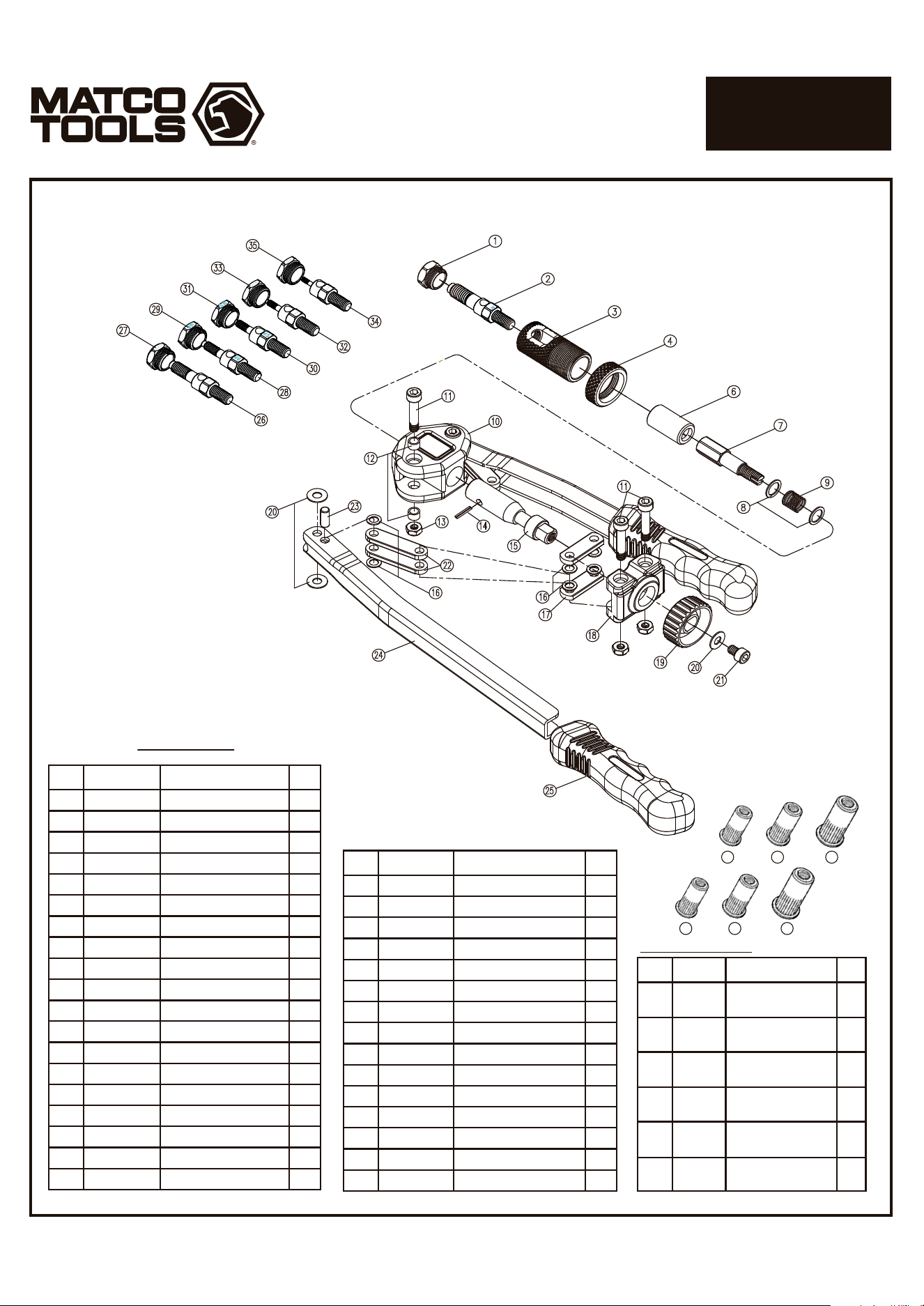
1
2
3
4
6
7
8
9
10
11
12
13
14
15
16
17
18
19
20
M8 Nosepiece
M8 Mandrel 8mmx1.25
Sleeve
Adjusting Nut
Hexagonal Sleeve
Riveting Bar
Spacer
Spring
Matco Main Body
Screw
Bushing
Locknut
Opening Spring Pins
Pulling Bar
Metal Washer
Connecting Bar
Main Shaft Drive
Knob
Spacer
1
1
1
1
1
1
2
1
1
4
4
4
1
1
8
2
1
1
5
Index Part No. Description Qty
1442-11
1442-08
1442-10
1442-02
1442-01
1442-A26
1442-A27
1442-A28
1442-A29
1442-A30
1442-A31
1442-A32
1442-A33
1442-A34
1442-A35
21
22
23
24
25
26
27
28
29
30
31
32
33
34
35
Screw
Connecting Bar
Bushing
Handle
Grip
Mandrel 5/16-18
5/16-18 Nosepiece
M6 Mandrel 6mmx1.0
M6 Nosepiece
M5 Mandrel 5mmx0.8
M5 Nosepiece
Mandrel 1/4-20
1/4-20 Nosepiece
Mandrel 10-24
10-24 Nosepiece
1
4
2
2
2
1
1
1
1
1
1
1
1
1
1
Index Part No. Description Qty
Parts List
1
1
1
1
1
1
M5 Rivet Nuts
(100pc/pk)
M6 Rivet Nuts
(100pc/pk)
M8 Rivet Nuts
(100pc/pk)
10-24 Rivet Nuts
(100pc/pk)
1/4-20 Rivet Nuts
(100pc/pk)
5/16-18 Rivet Nuts
(100pc/pk)
Also Sold Separately
RN5M
RN6M
RN8M
RN1024
RN14
RN516
36
37
38
39
40
41
Index Part No. Description Qty
36 37 38
39 40 41
13" NUT/THREAD
SETTER KIT
PARTS BREAKDOWN
8 11
Page 4
MNTS13
1508128-14MA