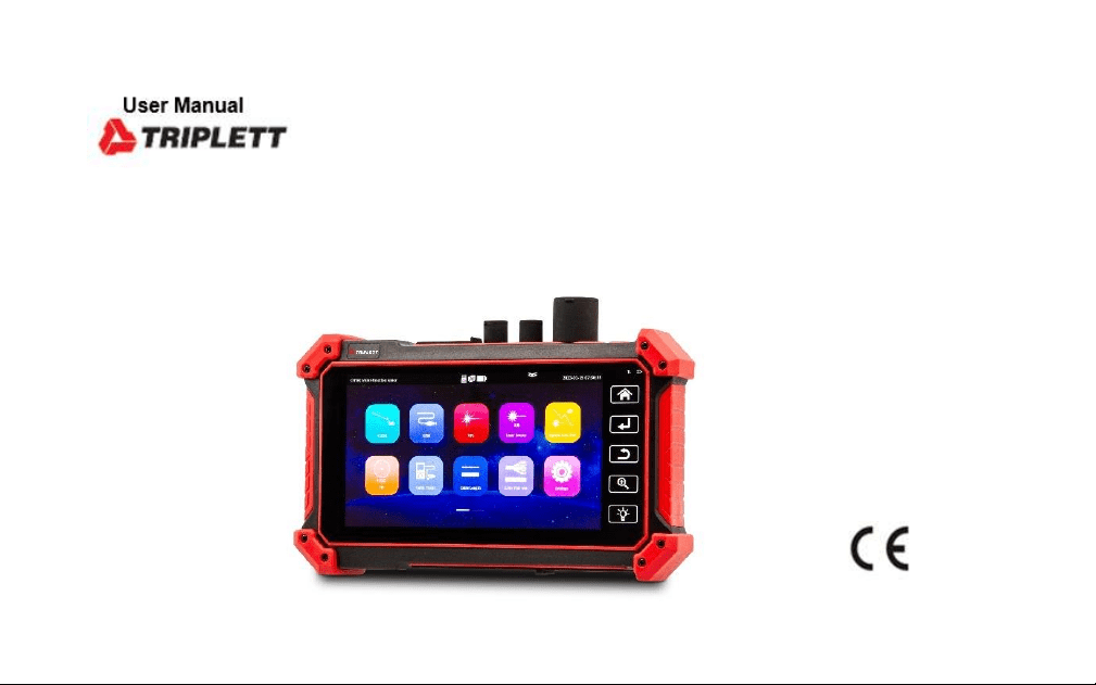
OTDR1315
Professional Multi-Function OTDR/Network Tool

Warning
****Avoid looking directly at the laser output port, laser will cause damage to human eyes! If don’t
user OTDR, VFL, OPM and laser source function, please turn off and cover with the protective cap
Do not disassemble the instrument since no component inside can be repaired by the user. ***

Safety Information
◼ The tester is intended to use in compliance with the local rules of the electrical usage and avoid
applying at the places which are inapplicable for the use of electrics such as hospital, gas station
etc.
◼ Please use the original accessories, to avoid damage the tester caused using non-certified
accessories.
◼ If there is any question or problem while using the Multi-function OTDR tester, or damages
occurred on the product, please contact our technical Department.
◼ Please take attention to the cleanliness of the machine interface, otherwise it may cause
inaccurate test results.
◼ The battery cable inside battery cabin should be disconnected for safety during transportation!
◼ When the system is abnormal, disconnect all external cables, press and hold the power button
until it automatically shuts down, and then restart the instrument.
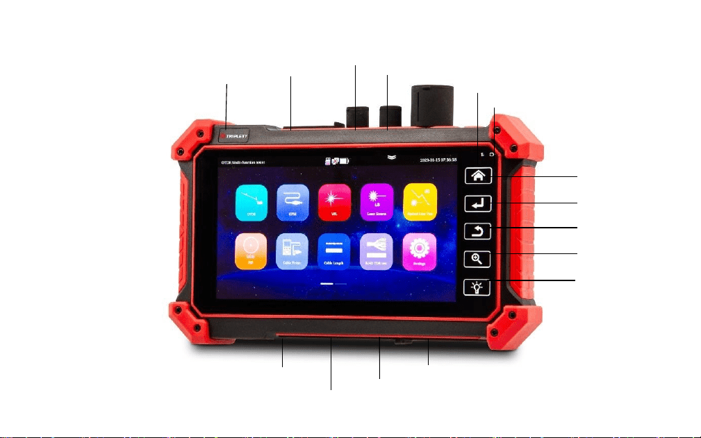
Menu key
Led key
Zoom key
Return key
Confirm key
Power
LAN port
Visual fault locator
Optical power meter
OTDR port
Standby indicator
Power indicator
UTP/SCAN
SD card slot
DC5V 1A power output
DC 5V 2A charging interface
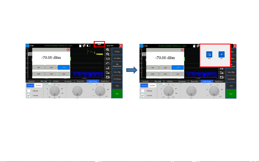
Drop-down menu
Drop-down button, call OSD menu, can test optical power meter, OTDR and visual fault
lower at the same time
Warning
Avoid looking directly at the laser output port, laser
will cause damage to human eyes!
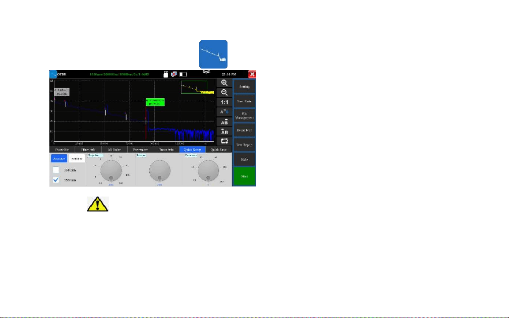
OTDR
1. Fiber connection
Connect the fiber to the top optical interface of
OTDR. It adopts SC-PC optical connector.
2. Auto OTDR test
Automatically set Pulse width and
measurement duration, the test time is 5s
3. Quick Setup
Quick test can set laser wavelength, distance
range, pulse width and measurement duration
parameters.
。
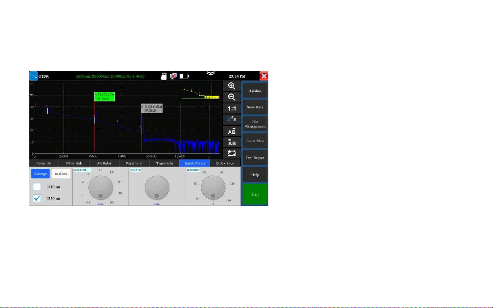
OTDR—Trace zoom
Horizontal amplification, enlarge the curve
horizontally.
Horizontal reduction, reduce the curve
horizontally.
1: 1 restore: restore the scaled curve in the
original 1:1 ratio.
the left and right arrow keys move a pole.
the pole A/B in the selected state will
move to the left.
the pole A/B in the selected state will
move to the right.
Tracking switch, switch between different
curves.
Use the center point of the two fingers as the center
to zoom
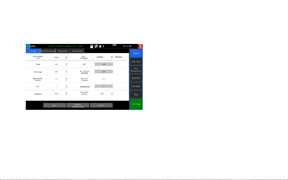
OTDR—Parameter setting
Laser wavelength: Selected by user, it provides
several options, wavelength of single mode fiber:
1310nm, 1550nm and 1610nm. (If the fiber over
100KM, please select 1550nm wavelength for testing,
Distance scope: 0.5km-200km
If the length is uncertain, it is recommended to use
automatic range, for known length, it is
recommended to use a range containing 1.5 times
the minimum length.
Measurement duration: 5s, 10s, 15s, 30s, 60s, 120s,
180s is optional. When need the meticulous and
smooth curve, can select the longer measurement
time.

Pulse width: Selected by user, 5ns~20000ns.
Measurement mode: Include “average measurement and real-time measurement”. When selected
real-time measurement mode, the selected duration of measurement won’t play role in the
measurement.
Refractivity: The default value is 1.4685. The refractivity is key parameter for calculating the
length, please don’t modify it at will.
Unit: Include “m and ft”
Reflection threshold: No option or user setting is provided in OTDR instrument.
Non-reflection threshold: Input scope: 0.01~2.99, the default value is: auto. When the manual
setting value is 0.00, it will transfer to auto value.

End threshold: It is used as the threshold value for looking over event point when the instrument
treating data, i.e.: event points that lower than the set value of end threshold will be removed, while the
event points that higher than the set value of bundling threshold will be displayed. For options set by
user, input scope is 1~19.99dB, the default value is: 5.00dB.
Optical warning of optical fiber: Options include “ON and OFF”, When in ON, if the optical fiber has
optical signal, the instrument will pop up alarm.
Default setting recovery: Distance scope is “auto”, pulse width is “auto”, duration of measurement is “5
s”, laser wavelength is “1550nm”, measurement mode is “average mode”, length unit is “meter”,
refractivity is “1.4685”, back scattering coefficient is “auto”, reflection threshold is “auto”, non-reflection
threshold is “auto”, end threshold is “5.0dB”, When finished setting, please click “Save” to save the
parameters.
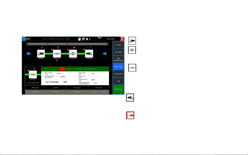
OTDR——Event map
Initial Event: The starting point of link.
Reflection Event: Connector, reflection event
is shown as peak signal.
Non-reflection Event: Fusion point or optical
fiber bending, non-reflection event is shown as
drop of optical power.
End Event: The terminal of fiber, the end event
with reflection peak is the normal end.
End Event: Optical fiber bending, the end
event with non-reflection peak is the fracture
Display the quantity of event, link loss, link
length, link attenuation coefficient. Click again
to switch to trace.
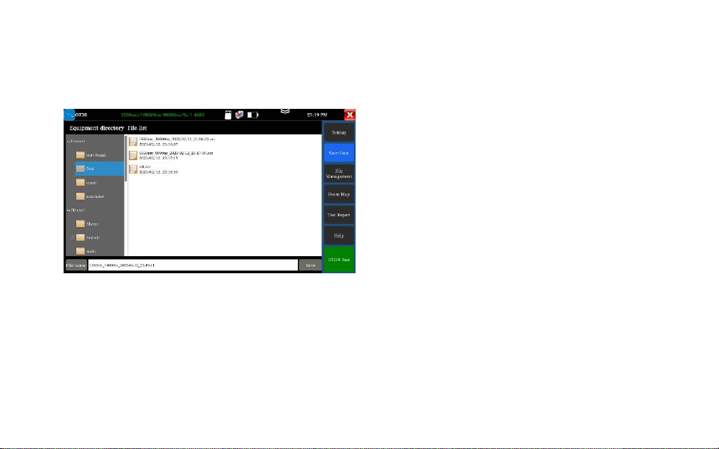
OTDR- File management
⚫ Save data: Select the directory to save SOR file
⚫ File management:Open, rename, copy and
delete the file
⚫ Test report:Create PDF file test report.
⚫ Help:OTDR user instruction
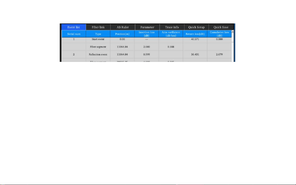
Click “Event list” to view the event list.
Serial number: Indicates the information of the nth event that currently displayed on the trace graph
Type: Indicates the event type of the event point.
Position: Indicates the distance from the initial point of the optical fiber to the event point.
Insertion loss: Indicates the quantity of plug-in loss of the event.
Attenuation coefficient: Indicates the attenuation characteristics of the optical fiber from the last event
point to the current event point.
Return loss: Reflect the reflection value of the event point.
Accumulate loss: Indicates the loss value of optical fiber from the initial point to the current event point
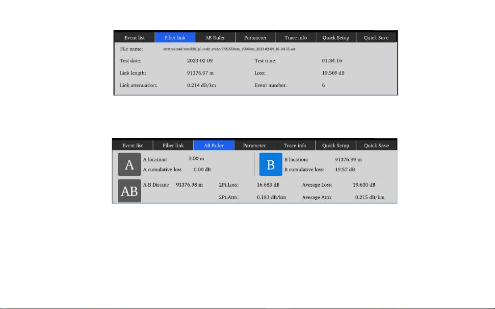
AB Ruler:Includes position of point A (or B), insertion loss of point A (or B), return coefficient
of point A (or B), accumulate loss of point A (or B), distance of A B section, loss between two
points of AB section, attenuation coefficient between two points of AB section, and LSA
attenuation coefficient of AB section
Optical fiber link: Includes file name, measurement date, measurement time, link length, link
loss, link attenuation coefficient, and quantity of event
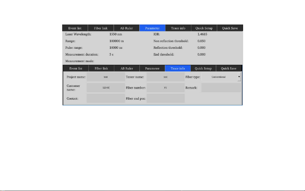
Measurement parameter includes laser wavelength, distance scope, pulse width, refractivity,
back scattering coefficient, reflection threshold, bundling threshold, non-reflection threshold,
and duration of measurement.
Trace information: Can editing project name, tester, fiber type, customer name, fiber number,
fiber end position, when save the report, will auto record this information.
Quick Save: auto name and save the file
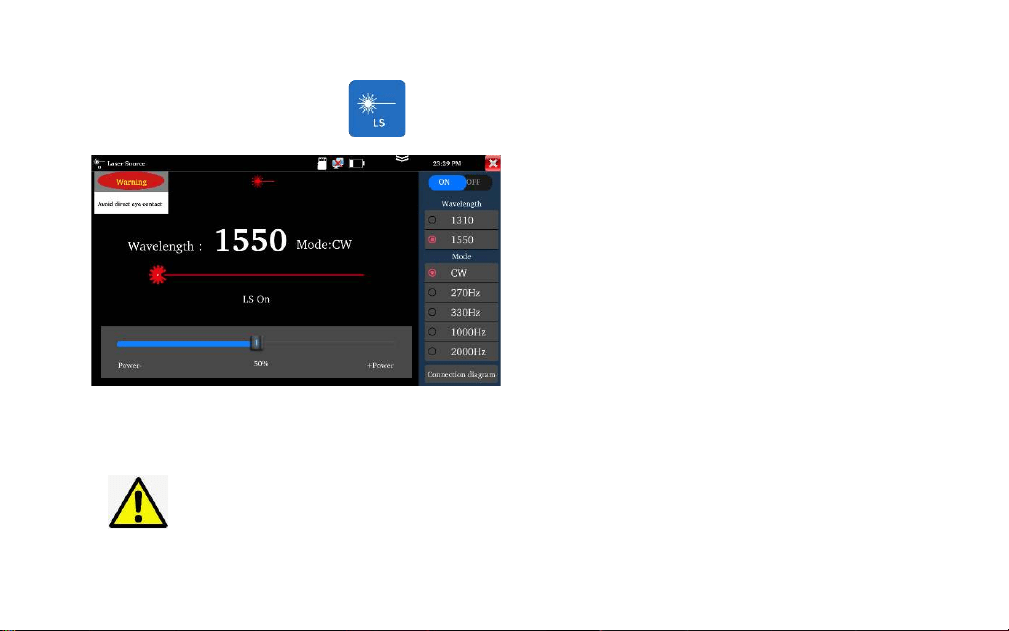
Laser source
Warning: Avoid looking directly at the laser output
port, laser will cause damage to human eyes!
It is used to engineering and maintenance of optical
fiber communication and CATV, fiber parameter
setting, the production and research of optical
components.
Open/Off: Turn on/off the laser source
Wavelength: 1310/1550/1610 are optional, the
wavelength same as OTDR module
Mode: Switch the frequency of laser source,
CW/270Hz/330Hz/1000Hz/20000Hz
Power: Through the slider to adjust the power,
the power range is 1-100
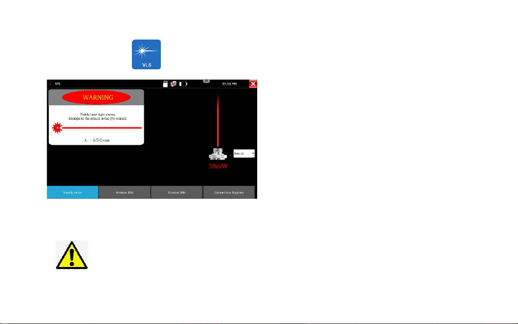
Visual fault location
Warning: Avoid looking directly at the laser output
port, laser will cause damage to human eyes!
It is used to determine the continuity of optical
fibers and locate faults
Steady mode: red laser source emits steady
Evasive mode: Evasive 1Hz" and "Evasive 2Hz", to
enter pulse mode, red laser source emits at a
certain frequency.
Time off: Time turn off can select the time
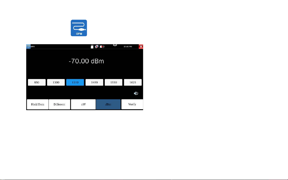
Optical power meter
Connect the measured fiber to OPM port, liner
or nonlinear optical power display, for optical
power testing and Fiber link loss relative
measurement.
with five wavelength 1625nm,1550nm, 1490nm,
1310nm,1300nm, 850nm
Hold date: Hold the display data
Difference: Save current value, then will display
the difference of new measurement value and
current value, can switch nW and dBm unit.
Note: Please keep the fiber connector and the
dust cap be clean and clean the detector with
the special alcohol.
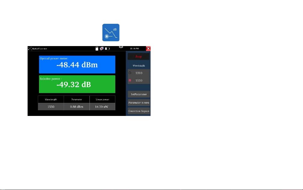
Loss test
It is used to test the insertion loss of optical
passive devices.
Calibration: Connect standard jumper to meter’s
OTDR and LS port, click “Start”, after power is
stable, click “Set Parameter”
Usage: After setting the reference value, let’s
talk about the optical device being connected to
the OTDR and LS interface of the instrument,
click “Start”, the relative power on the interface
is insertion loss value of the tested device
Note: Please calibrate before each test, the test
results will be more accurate
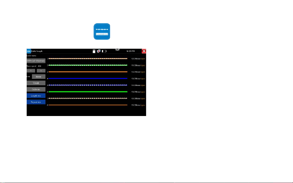
Length test
It is used to measure cable’s length in the open
status.
Usage: Insert accessory RJ45 to BNC converter
into the UTP port and connect alligator clip to its
BNC interface. The measured cable needs to be
peeled out and exposed the copper core.
Cable type: BNC cable, network cable, RVV
control cable, Telephone line and TVVB cable etc
Length test: measure the cable length.
Repeat test” can continue to test cable length,
The short-
circuit status will not display the cable length
Note: The measured cable cannot be connecte
d to any device. If connected to other devices,
it will cause incorrect measurement results!
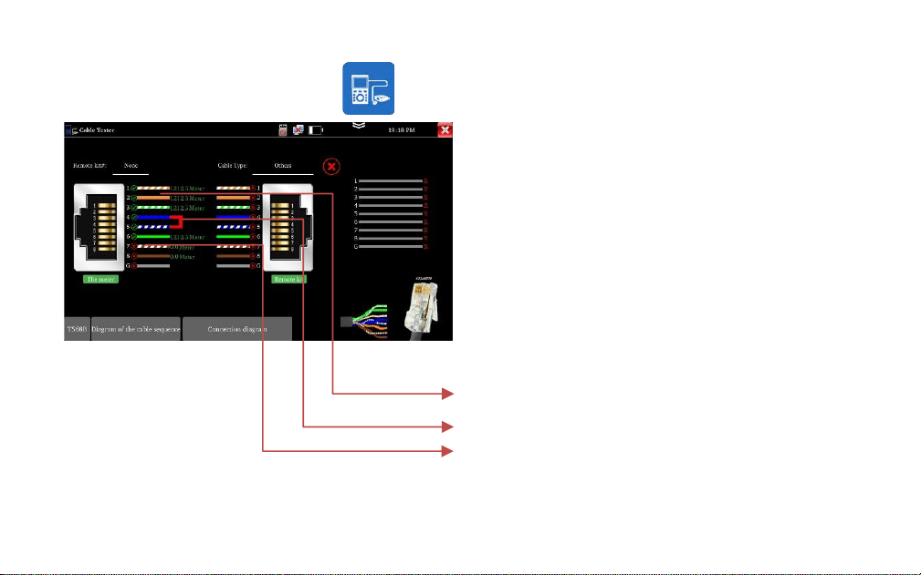
UTP cable test
Test cable’s continuity, length and fault locator of RJ45
cable connector. The number of the cable tester is 255.
Connect LAN cable or telephone cable to UTP port of
tester, the other end doesn’t connect any device, can test
fault locator of RJ45 cable connector and cable length. the
other end connects to UTP port of wire receiver, enter
cable test app to test cable’s continuity and sequence.
1. The cable is normal, can test cable length
2. The cable is short circuit
3. The RJ45 cable connector is faulty, or a breakpoint 1
meter away from the RJ45 cable connector
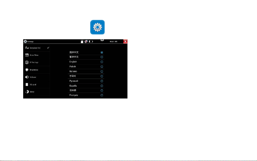
Setting
Language: Support English, Chinese, Korean, Russian,
Italian, Polish, Spanish, French or Japanese, German,
Turkish, etc.
Date/Time: Set the Date/time of the IP tester
IP setting: Manually set the IP address, Subnet Mask,
Default Gateway and DNS address (Optional)
Brightness: Set the desired brightness of the tester
Volume: Set volume level
SD Card: Displays SD Card Capacity. You can also
format the SD card or unmount it before removing it.
Power off: can select 1/2/5/10/20 minutes, auto
power off
Version information: Shows applications version
information
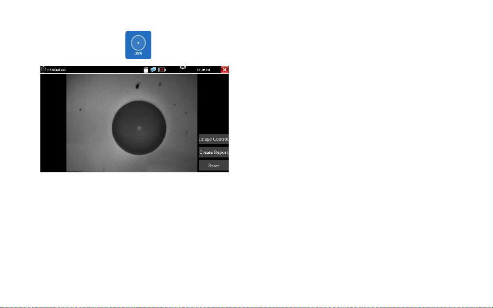
Fiber end inspection
It is used to inspecting the cleanliness of the
fiber end face
Parameter setting: Adjust the image brightness
and contrast
Create report: Create the PDF file
Reset: Reset the fiber lens
Note: Not includes fiber end device
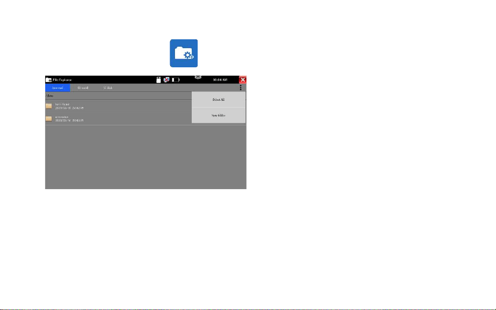
File Explorer
It is used to view the report and picture.
Click "File" on the top bar tool, can select
internal or external storage. Click on the upper
right corner Icon"... ". will pop-up menu, you
can select other operation or create new folder.
otdr:Save the OTDR file
report:Save test report
screenshot:Save screenshot and picture
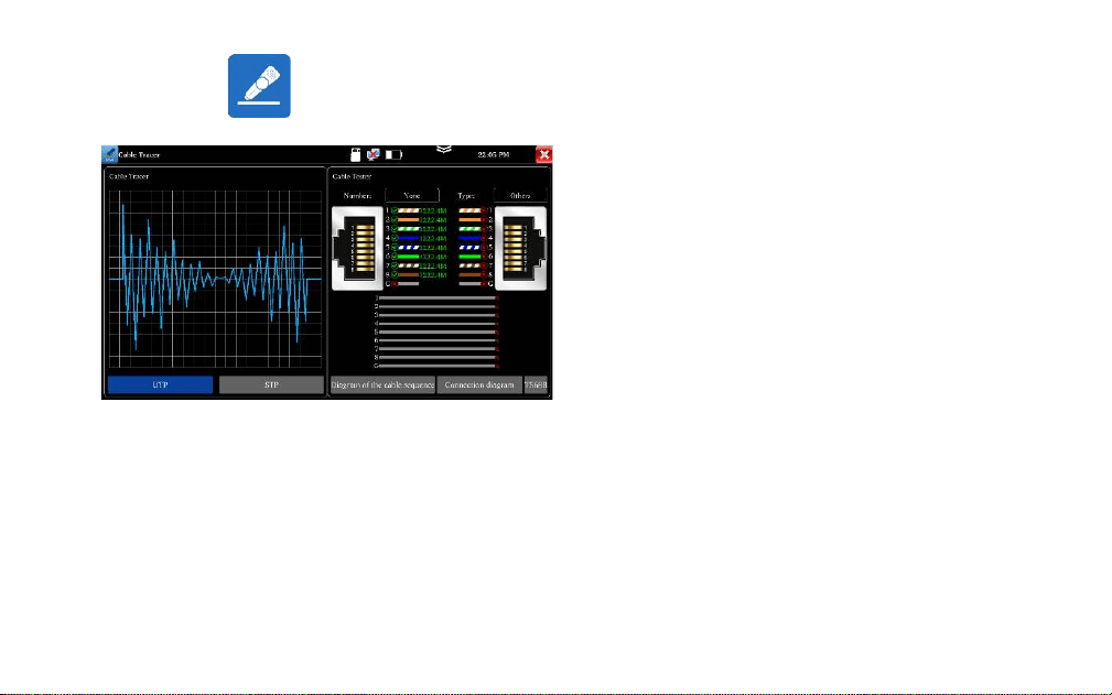
Connect the other end of the tested network cable to the "UTP" port of cable tracer, the cable
sequence, continuity, test box number and network cable type will be displayed on the right side of
the meter interface.
The "G" indicates the continuity of the shielded network cable. The 1-8 indicators of cable tracer will
flash according to the cable sequence. The DIRECT / CROSS / OTHER three indicator lights display the
type of network cable directly.
Connect tested cable or BNC cable to the UTP
port
Support UTP mode and STP mode.
Cable tracer and Cable tester can be tested at
the same time. It is better to judge whether the
search network cable is accurate.
Digital cable tracer
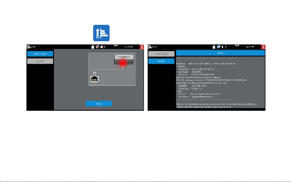
Quickly find the connected Ethernet cable
Click "Start". The tester will send special signals to
make the connected LAN port flicker at special
frequency
Used to detect the main capabilities, management
addresses, device identification, interface
identification, and other information of switches and
other devices.
Note: The switch support LLDP protocol.
Port Flashing
Connect cable to the LAN port of tester, the other
end connects or disconnect other device. Enter
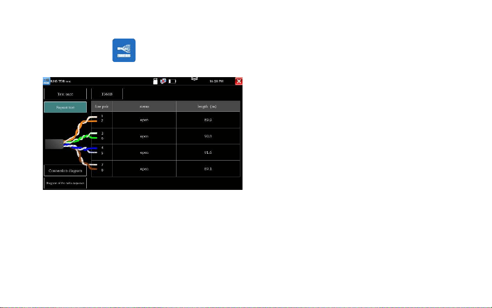
“RJ45 cable TDR test” app to test cable’s length.
Test cable’s length, please don’t connect any
device. The max measurement length is 600
meters.
If cable is open circuit or short circuit, can test the
cable length, if screen display "online", the testing
result would be not accurate.
RJ45 Cable TDR test
Used to copy and edit the files from the SD card
without the use of SD card reader.
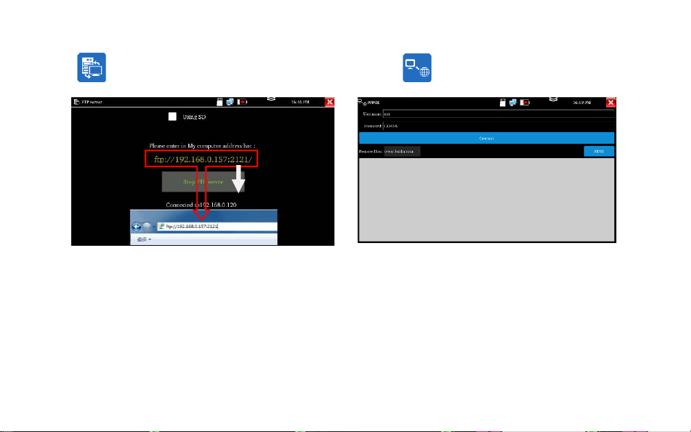
Start the FTP server and then input the tester's
FTP address in the PC's address bar.
Used to detect whether broadband PPPOE dialing
is normal.
Connect the network cable to the LAN port of
tester, enter the username and password, click
“OK” to dialing test. After the dialing is successful,
click “PING” to detect the internet
FTP Server
PPPOE
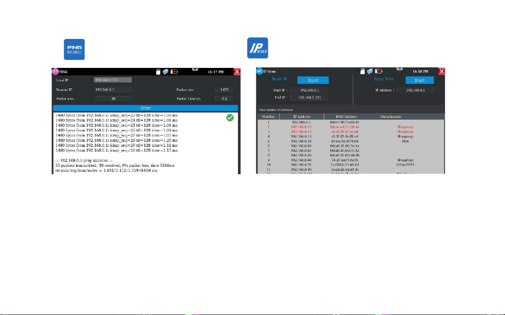
PING
IP Scan (Optional)
It is used for quickly find the IP address of the
IP camera or other device connected to the
instrument, supporting scanning MAC
address, camera manufacturer, and scanning
for IP conflicts.
It is used for testing if the connected IP camera
or other network equipment's Ethernet port is
working normally, and the IP address is
correct.

Specifications
Model
OTDR1315
OTDR with Network function
Screen & Display
5.55 inch OLED screen display, 1280*720 resolution
Wavelength(nm)
1310/1550
Dynamic range (dB)
26/24
Event blind zone (m)
≤1.6
Attenuation blind zone (m)
≤8
Distance scope (Km)
0.5、1、2、5、10、25、50、100、200
Pulse width (ns)
5, 10, 20, 30, 50, 80, 160, 300, 500, 800, 1000, 2000, 4000, 6000, 10000, 20000
Distance uncertainty
±(1 m + 5×10
-5
× distance + sampling interval)
Measurement duration
5s~3min
Linearity (dB/dB)
±0.05
Minimum distance
(m)
0.05
Sampling point (K)
32-128

Loss threshold (dB)
0.05
Loss resolution ratio (dB)
0.01
File format
SOR standard format/PDF
Storage
FLASH (EMMC)8G + Support TF card (NOT included)
OTDR Interface type
SC-UPC
UTP cable tester
Test UTP cable connection status and display it on the screen. Read the number on the screen.
detect the near-end, mid-end and far-end fault point of RJ45 cable connector, also can test shield
cable
Optical power meter
Wavelength:1625,1550nm,1490nm,1310nm,1300nm,850nm, measurement range,-70 ~ +6 dBm,
for optical power testing and Fiber link loss relative measurement
Visual fault locator
10mW visual fault locator with 650nm wavelength, emit red laser sources to test multi-mode and
single mode fiber’s bending and breakage, test range 8KM
Laser source
Output wavelength same as OTDR, can adjust power

USB 5V power output
5V 1A power output, as the power bank
Network port
10/100/1000M auto adapt (optional)
RJ45 cable TDR test
Test cable’s length, Max testing up to 600 meter
Cable length
Test cable’s length, max testing up to 3km
Network tool
IP Scan, PPPOE, port flashing, Ping test, FTP server
Cable tracer+Electroscope
Included
Optional
External power supply
Type-c 5V(2A)
Battery
Built-in 3.7V Lithium polymer battery, 4000mAh
Rechargeable
After charging 3.5 hours, normal working time 6 hours
Operation setting
OSD menu, language: English, Portuguese, Korean, Russian, Italian, French, Polish, Spanish,
Japanese, Turkish, Deutsch, Serbian, Czech, Vietnamese etc
Auto off
5-30 (mins)
Working Temperature
-10℃---+50℃
Working Humidity
30%-90%

Dimension/Weight
183mm x 110mm x 36.5mm /0.45kg
Remarks:
1. The technical specification describes the ensured performance of the instrument when using typical PC model connector to
measure, without considering the uncertainty caused by optical fiber refractivity.
2. Dynamic range is the data measured under the condition of the maximum pulse width and 3 minutes of average time.
Dynamic range is the data measured under the condition of 200km/20000ns/3min.
3. Measuring conditions of blind zone: reflection event is within 5Km, reflection strength is 45dB. Measured by the minimum
pulse width
4. The data above is only for reference and any change of them will not be informed in advance.