
3
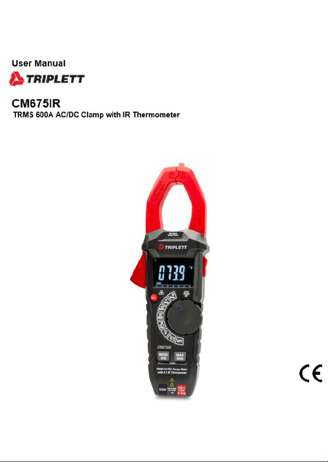
AC/DC TRMS Clamp Meter with IR Thermometer
Page
4
4
4
5
5
6
7
8
8
9
10
11
12
13
14
15
16
17
18
19
20
20
22
Content
1.Safety..........................................................................................
1-1.International Safety Symbols..................................................
1-2.Safety Notes...........................................................................
2.Description..................................................................................
2-1.Meter Description...................................................................
2-2.Symbols Used on LCD Display.................................................
3.Button Function...........................................................................
4.Operation.....................................................................................
4-1.AC/DC Current Measurement...................................................
4-2.DC Voltage Measurement........................................................
4-3.AC Voltage Measurement........................................................
4-4.Resistance Measurement........................................................
4-5.Diode Test..............................................................................
4-6.Continuity Measurement.........................................................
4-7.Capacitance Measurement......................................................
4-8.Frequency & % Duty Cycle Measurement.................................
4-9.Type K Temperature Measurement...........................................
4-10.IR Temperature Measurement................................................
4-11.Non-Contact AC Voltage Measurement...................................
5.Battery Replacement....................................................................
6.Specifications..............................................................................
6-1.Technical Specifications.........................................................
6-2.General Specifications............................................................
4
AC/DC TRMS Clamp Meter with IR Thermometer
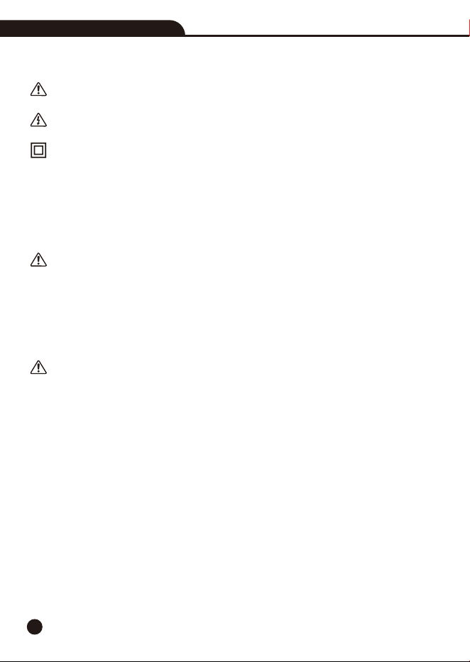
1.Safety
1-1.International Safety Symbols
This symbol, adjacent to another symbol or terminal, indicates the user must refer to the
manual for further information.
This symbol, adjacent to a terminal, indicates that, under normal use, hazardous voltages
may be present.
Double Insulation
1-2.Safety Notes
• Do not exceed the maximum allowable input range of any function.
• Do not apply voltage to meter when resistance function is selected.
• Set the function switch OFF when the meter is not in use.
WARNINGS
• Set function switch to the appropriate position before measuring.
• When measuring volts do not switch to current/resistance modes.
• When changing ranges using the selector switch always disconnect the test leads from the
circuit under test.
• Do not exceed the maximum rated input limits.
CAUTIONS
• Improper use of this meter can cause damage, shock, injury or death, read and understand this
user manual before operating the meter.
• Always remove the test leads before replacing the battery.
• Inspect the condition of the test leads and the meter itself for any damage before operating the
meter, repair or replace any damage before use.
• Use great care when making measurements if the voltages are greater than 25VAC rms or 35VDC,
these voltages are considered a shock hazard.
• Remove the battery if the meter is to be stored for long periods.
• Always discharge capacitors and remove power from the device under test before performing
Diode, Resistance or Continuity tests.
• Voltage checks on electrical outlets can be difficult and misleading because of the uncertainty
of connection to the recessed electrical contacts, other means should be used to ensure that
the terminals are not “live”.
• If the equipment is used in a manner not specified by the manufacturer, the protection provided
by the equipment may be impaired.
5
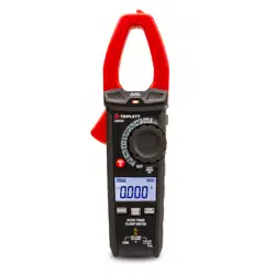
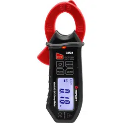
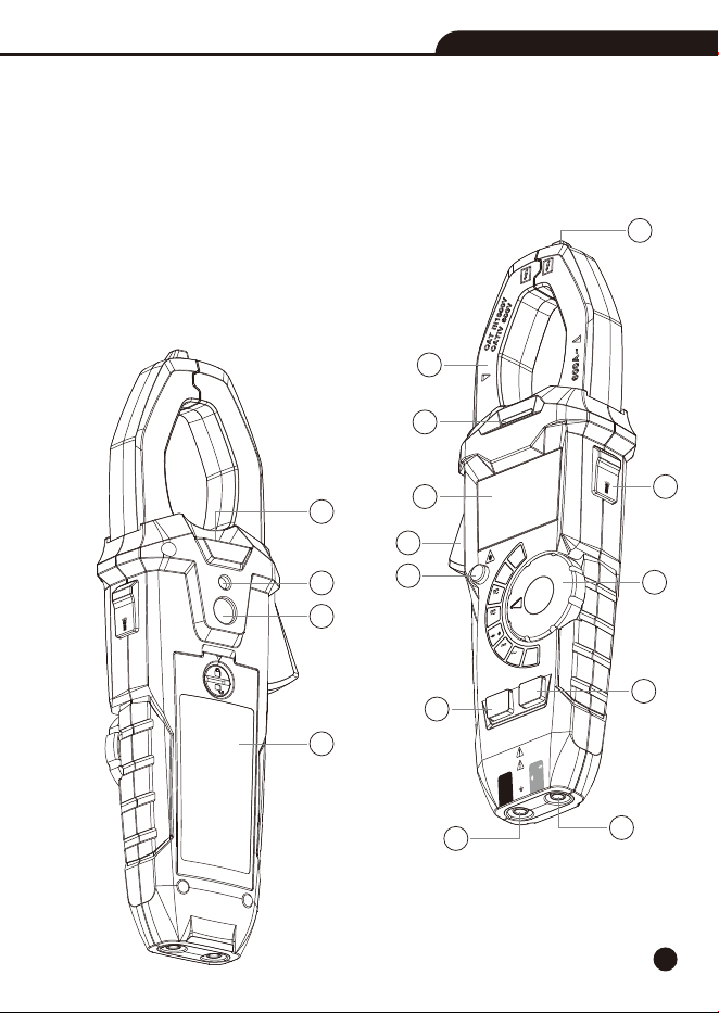
2.Description
2-1.Meter Description
1-Non-Contact AC Voltage Indicator
2-Current Clamp
3-Non-Contact AC Voltage Indicator Light
4-LCD Display
5-Clamp Trigger
6-Relative/Laser Button
7-Data Hold/Flashlight Button
8-Rotary Function Switch
9-MODE/VFD Button
10-MAX/MIN Button
11-COM Input Jack
12-Positive Input Jack
13-Flashlight
14-Laser Hole
15-IR Sensor
16-Battery Cover
AC/DC TRMS Clamp Meter
with IR Thermometer
CAT III
1000V
CAT
IV 600V
COM
CAP
K-Temp
V
Ω
AUTO
POWER
OFF
OFF
V
Hz
V
IR
Temp
K
Temp
60A
CAP
Ω
%
600A
MAX
MIN
MODE
VFD
HOLD
REL
Non-Cont
ac
t
Voltage De
t
ector
2
4
5
7
8
6
9
10
11
12
3
1
HOLD
14
15
16
13
AC/DC TRMS Clamp Meter with IR Thermometer
6
235674891
13
14
12
1011
15
17
16
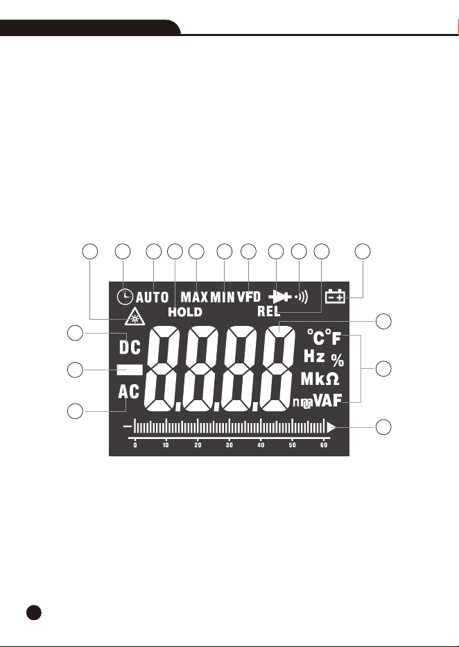
2-2.Symbols Used on LCD Display
1-IR Laser Point
2-Auto Power Off
3-Auto Range mode
4-Data Hold
5-Maximum
6-Minimum
7-VFD Mode
8-Diode Test
9-Continuity Test
10-Relative Mode
11-Low Battery
12-Measurement Display Digits
13-Units of Measure List
14-Analog Bargraph
15-Alternating Current
16-Negative Reading Display
17-Direct Current
AC/DC TRMS Clamp Meter with IR Thermometer

7
3.Button Function
3-1.Relative/Laser Button
• Press the REL/Laser Button to enter the relative value measurement mode, take the current
value as the reference and obtain the relative value.
• In DCA mode, it can also be used as DCA zeroing.
• Long press the REL/Laser Button, you can turn on the laser to guide in IR-Temp measurement
mode, and then press this Button to turn off the laser.
3-2.Data Hold/Flashlight Button
• To freeze the LCD meter reading, press the Data Hold/Flashlight Button, while data hold is
active, the “HOLD” display icon appears on the LCD.
• Press the Data Hold/Flashlight Button again to return to normal operation.
• Long press the Data Hold/Flashlight Button to turn on the flashlight, then press the turn off
flashlight.
3-3.MODE/VFD Button
• Press the MODE/VFD Button to select ACA/DCA, Diode/Continuity/CAP, VAC/Hz/%, °C/°F.
• In ACV mode, long press the MODE/VFD Button to enter VFD measurement mode and display
VFD.
• In VFD mode, low-pass filter can reduce the high-frequency noise when measuring AC voltage.
• VFD mode is mainly used for AC voltage measurement of variable frequency drive and frequency
converter.
3-4.MAX/MIN Button
• Press the MAX/MIN Button to enter MAX, MIN Recording mode (Manual range only ).
• Select the proper range before selecting MAX MIN to ensure that the MAX/MIN reading will not
exceed the testing range.
• Press once to select MIN, press again to select MAX and press again release MAX/MIN recording
function.
AC/DC TRMS Clamp Meter with IR Thermometer
8
4.Operation
Notes: Read and understand all WARNING and Precaution statements listed in the safety section
of this operation manual prior to using this meter.
Notes: Set the function select switch to the OFF position when the meter is not in use.
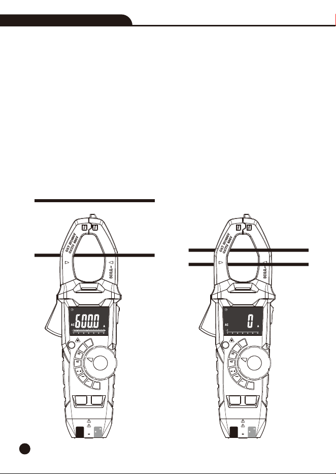
4-1.AC/DC Current Measurement
WARNING: Ensure that the test leads are disconnected from the meter before making current
clamp measurements.
1.Set the Function switch to the 600A or 60A AC/DC range, if the range of the measured is not
known, select the higher range first then move to the lower range if necessary.
2.Press the MODE/VFD Button to switch the AC or DC measurement.
3.Press the trigger to open jaw, fully enclose one conductor to be measured.
4.The clamp meter LCD will display the reading.
No
Yes
AC/DC TRMS Clamp Meter with IR Thermometer
AC/DC TRMS Clamp Meter
with IR Thermometer
CAT III 1000V
CAT IV 600V
COM
CAP
K-Temp
V
Ω
REL
MAX
MIN
MODE
VFD
AUTO
POWER
OFF
OFF
V
Hz
V
IR
Temp
K
Temp
60A
CAP
Ω
%
600A
Non-Contact
Voltage Detector
AC/DC TRMS Clamp Meter
with IR Thermometer
CAT III 1000V
CAT IV 600V
COM
CAP
K-Temp
V
Ω
REL
MAX
MIN
MODE
VFD
AUTO
POWER
OFF
OFF
V
Hz
V
IR
Temp
K
Temp
CAP
Ω
%
Non-Contact
Voltage Detector
60A
600A
9
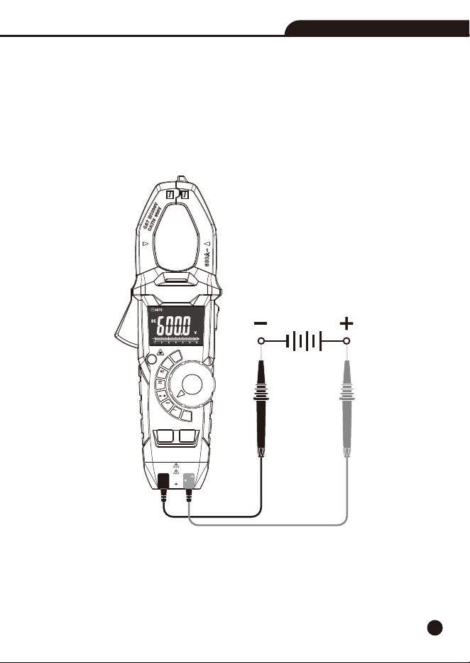
4-2.DC Voltage Measurement
1.Set the function switch to the VDC Position.
2.Insert the black test lead into the COM Input Jack and the red test lead into the Positive Input
Jack.
3.Connect the test leads in parallel to the circuit under test.
4.Read the DC Voltage measurement on the LCD display.
AC/DC TRMS Clamp Meter with IR Thermometer
AC/DC TRMS Clamp Meter
with IR Thermometer
CAT III 1000V
CAT IV 600V
COM
CAP
K-Temp
V
Ω
REL
MAX
MIN
MODE
VFD
AUTO
POWER
OFF
OFF
V
Hz
V
IR
Temp
K
Temp
CAP
Ω
%
Non-Contact
Voltage Detector
60A
600A
10
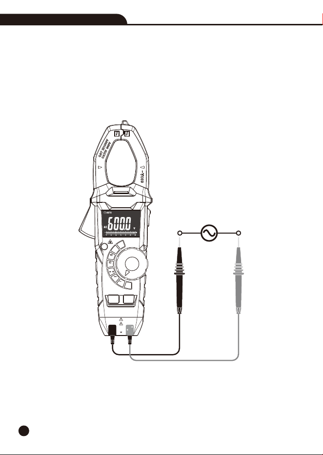
4-3.AC Voltage Measurement
1.Set the function switch to the VAC/Hz% Position.
2.Insert the black test lead into the COM Input Jack and the red test lead into the Positive Input
Jack.
3.Connect the test leads in parallel to the circuit under test.
4.Read the AC Voltage measurement on the LCD display.
AC/DC TRMS Clamp Meter with IR Thermometer
AC/DC TRMS Clamp Meter
with IR Thermometer
CAT III 1000V
CAT IV 600V
COM
CAP
K-Temp
V
Ω
REL
MAX
MIN
MODE
VFD
AUTO
POWER
OFF
OFF
V
Hz
V
IR
Temp
K
Temp
CAP
Ω
%
Non-Contact
Voltage Detector
60A
600A
11
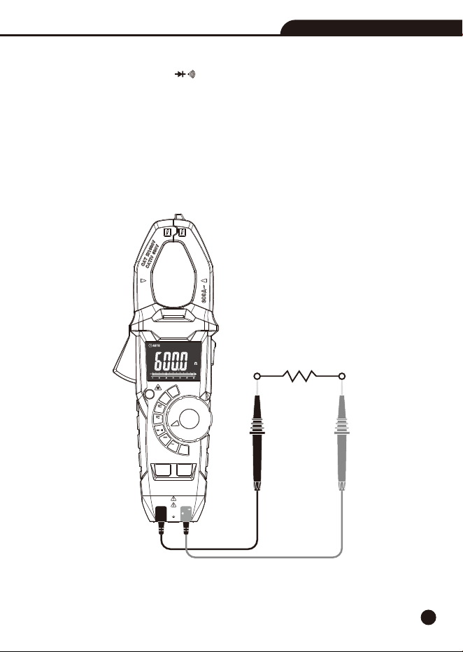
4-4.Resistance Measurement
1.Set the function switch to the CAP Position.Ω
2.Insert the black test lead into the COM Input Jack and the red test lead into the Positive Input
Jack.
3.Press the MODE/VFD Button until “” appears in the display.Ω
4.Touch the test probe tips across the circuit or component under test, it is best to disconnect one
side of the device under test so the rest of the circuit will not interfere with the resistance reading.
5.For Resistance tests, read the resistance on the LCD display.
AC/DC TRMS Clamp Meter with IR Thermometer
AC/DC TRMS Clamp Meter
with IR Thermometer
CAT III 1000V
CAT IV 600V
COM
CAP
K-Temp
V
Ω
REL
MAX
MIN
MODE
VFD
AUTO
POWER
OFF
OFF
V
Hz
V
IR
Temp
K
Temp
CAP
Ω
%
Non-Contact
Voltage Detector
60A
600A
12
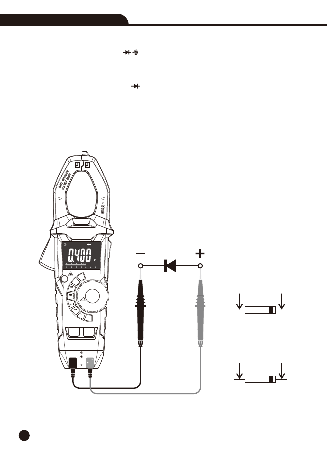
4-5.Diode Test
1.Set the function switch to the CAP Position.Ω
2.Insert the black test lead into the COM Input Jack and the red test lead into the Positive Input
Jack.
3.Press the MODE/VFD Button until “ ” appears in the display.
4.Touch the test probes to the diode under test.
• Forward voltage will indicate 0.4V to 0.7V, Reverse voltage will indicate “OL”.
• Shorted devices will indicate near 0mV and an open device will indicate “OL” in both polarities.
Forward Test
Red
Probe
Black
Probe
Black
Probe
Red
Probe
Reverse Test
AC/DC TRMS Clamp Meter with IR Thermometer
AC/DC TRMS Clamp Meter
with IR Thermometer
CAT III 1000V
CAT IV 600V
COM
CAP
K-Temp
V
Ω
REL
MAX
MIN
MODE
VFD
AUTO
POWER
OFF
OFF
V
Hz
V
IR
Temp
K
Temp
CAP
Ω
%
Non-Contact
Voltage Detector
60A
600A

13
4-6.Continuity Measurement
1.Set the function switch to the CAP Position.Ω
2.Insert the black test lead into the COM Input Jack and the red test lead into the Positive Input
Jack.
3.Press the MODE/VFD Button until “ ” appears in the display.
4. Touch the test probe tips across the circuit or component under test.
5. If the resistance is <50, a tone will sound.Ω
AC/DC TRMS Clamp Meter with IR Thermometer
AC/DC TRMS Clamp Meter
with IR Thermometer
CAT III 1000V
CAT IV 600V
COM
CAP
K-Temp
V
Ω
REL
MAX
MIN
MODE
VFD
AUTO
POWER
OFF
OFF
V
Hz
V
IR
Temp
K
Temp
CAP
Ω
%
Non-Contact
Voltage Detector
60A
600A
14
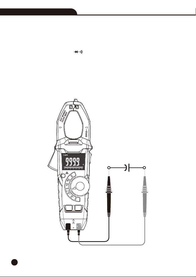
4-7.Capacitance Measurement
WARNING: To avoid electric shock, disconnect power to the unit under test and discharge all
capacitors before taking any capacitance measurements. Remove the batteries and unplug the
line cords.
1.Set the function switch to the CAP Position.Ω
2.Insert the black test lead into the COM Input Jack and the red test lead into the Positive Input
Jack.
3. Press the MODE/VFD Button select capacitance measurement.
4. Touch the test leads to the capacitor to be tested.
5. Read the capacitance value in the display
AC/DC TRMS Clamp Meter with IR Thermometer
AC/DC TRMS Clamp Meter
with IR Thermometer
CAT III 1000V
CAT IV 600V
COM
CAP
K-Temp
V
Ω
REL
MAX
MIN
MODE
VFD
AUTO
POWER
OFF
OFF
V
Hz
V
IR
Temp
K
Temp
CAP
Ω
%
Non-Contact
Voltage Detector
60A
600A
15
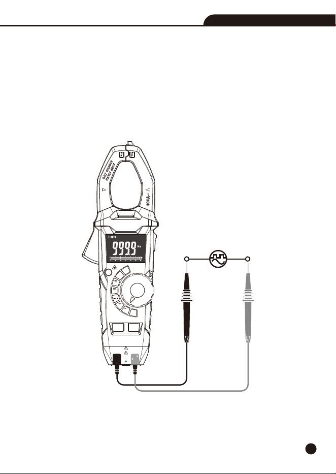
4-8.Frequency & % Duty Cycle Measurement
1.Set the function switch to the VAC/Hz% Position.
2.Insert the black test lead into the COM Input Jack and the red test lead into the Positive Input
Jack.
3.Press MODE/VFD Button to select the Frequency (Hz) or Duty cycle (%).
4.Touch the test probe tips across the part under test.
5.Read the value on the display, the display will indicate the proper decimal point and value.
AC/DC TRMS Clamp Meter with IR Thermometer
AC/DC TRMS Clamp Meter
with IR Thermometer
CAT III 1000V
CAT IV 600V
COM
CAP
K-Temp
V
Ω
REL
MAX
MIN
MODE
VFD
AUTO
POWER
OFF
OFF
V
Hz
V
IR
Temp
K
Temp
CAP
Ω
%
Non-Contact
Voltage Detector
60A
600A
16
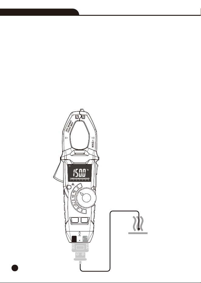
4-9.Type K Temperature Measurement
WARNING: To avoid electric shock, disconnect both test probes from any source of voltage before
making a temperature measurement.
1.Set the function switch to the K Temp Position.
2.Insert the Temperature Probe into the COM and Positive Input Jack, making sure to observe the
correct polarity.
3.Touch the Temperature Probe head to the part whose temperature you wish to measure, keep the
probe touching the part under test until the reading stabilizes (about 30 seconds).
4.Read the temperature in the display, the digital reading will indicate the proper decimal point
and value.
WARNING: To avoid electric shock, be sure the thermocouple has been removed before changing
to another measurement function.
AC/DC TRMS Clamp Meter with IR Thermometer
AC/DC TRMS Clamp Meter
with IR Thermometer
CAT III 1000V
CAT IV 600V
COM
CAP
V
Ω
REL
MAX
MIN
MODE
VFD
AUTO
POWER
OFF
OFF
V
Hz
V
IR
Temp
K
Temp
CAP
Ω
%
Non-Contact
Voltage Detector
K-Temp
60A
600A
17
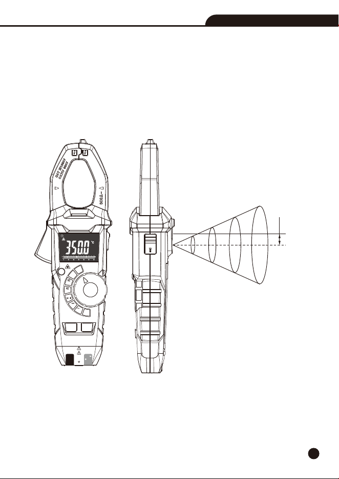
4-10.IR Temperature Measurement
1.Set the function switch to the IR Temp Position.
2.Let the instrument aim at the object which will be measured, the reading will display on the LCD.
3.Press the REL/Laser Button to switch on or off laser.
4.Press the MAX/MIN Button to select MAX/MIN, long press to exit.
5.Press the Data Hold/Flashlight Button, the data will freeze on the display, and then press to
unfreeze.
HOLD
Laser
IR
inch
mm
32@8
16@4
8@2
4@1
812.8@203.2
406.4@101.6
203.2@50.8
101.6@25.4
11
D:S=4:1
AC/DC TRMS Clamp Meter with IR Thermometer
AC/DC TRMS Clamp Meter
with IR Thermometer
CAT III 1000V
CAT IV 600V
COM
CAP
K-Temp
V
Ω
REL
MAX
MIN
MODE
VFD
AUTO
POWER
OFF
OFF
V
Hz
V
IR
Temp
K
Temp
CAP
Ω
%
Non-Contact
Voltage Detector
60A
600A
18
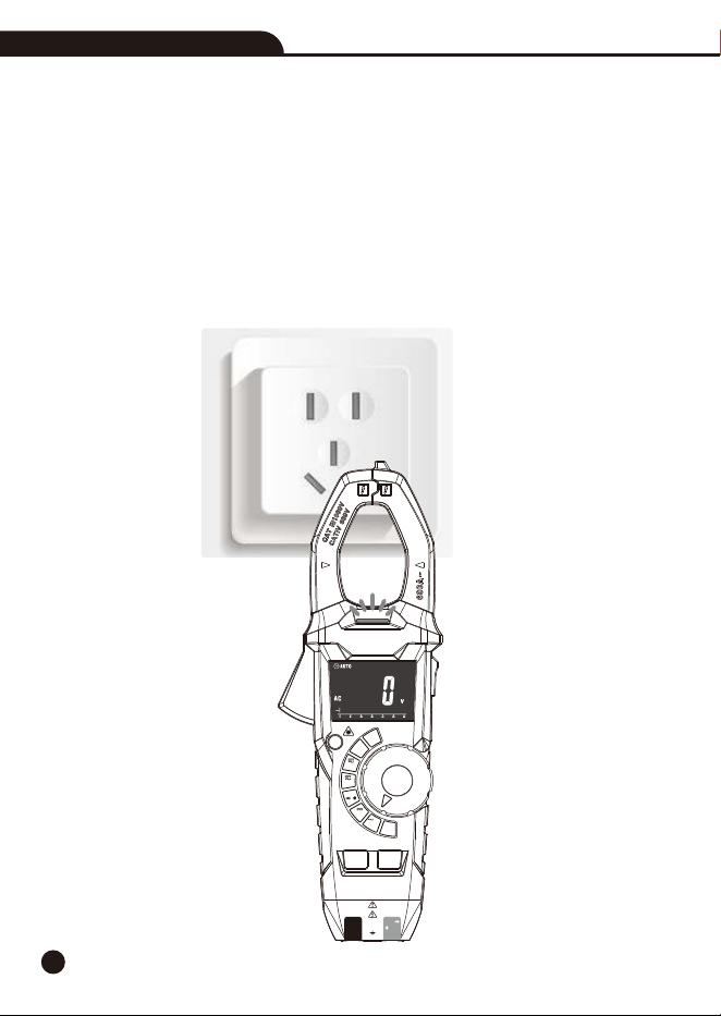
4-11.Non-Contact AC Voltage Measurement
WARNING: Risk of Electrocution. Before use, always test the Voltage Detector on a known live
circuit to verify proper operation.
1.Touch the probe tip to the hot conductor or insert into the hot side of the electrical outlet.
2.If AC voltage is present, the detector light will illuminate.
Note: The conductors in electrical cord sets are often twisted. For best results, rub the probe tip
along a length of the cord to assure placing the tip in close proximity to the live conductor.
Note: The detector is designed with high sensitivity. Static electricity or other sources of energy
may randomly trip the sensor, this is normal operation.
AC/DC TRMS Clamp Meter with IR Thermometer
AC/DC TRMS Clamp Meter
with IR Thermometer
CAT III 1000V
CAT IV 600V
COM
CAP
K-Temp
V
Ω
REL
MAX
MIN
MODE
VFD
AUTO
POWER
OFF
OFF
V
Hz
V
IR
Temp
K
Temp
CAP
Ω
%
Non-Contact
Voltage Detector
60A
600A

19
5.Battery Replacement
1. Remove the one rear head screw.
2. Open the battery compartment.
3. Replace the requires three “AAA” 1.5V Battery.
4. Re-assemble the meter.
AC/DC TRMS Clamp Meter with IR Thermometer
20
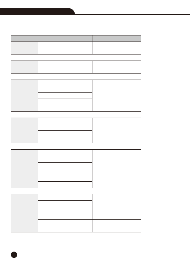
6.Specifications
6-1.Technical Specifications
AC/DC TRMS Clamp Meter with IR Thermometer
Range
60A
600A
60A
600A
600mV
6V
60V
600V
1000V
6V
60V
600V
1000V
600
6k
60k
600k
6M
60M
999.9nF
9.999µF
99.99µF
999.9µF
9.999mF
99.99mF
Accuracy
±(2.8% + 8 digits)
±(2.8% + 5 digits)
±(1.5% + 10 digits)
±(0.8% + 4 digits)
±(1.2% + 5 digits)
±(1.5% + 5 digits)
±(1.5% + 6 digits)
±(2.0% + 5 digits)
±(2.8% + 10 digits)
±(4% + 6 digits)
±(6% + 15 digits)
Resolution
0.01A
0.1A
0.01A
0.1A
0.1mV
0.001V
0.01V
0.1V
1V
0.001V
0.01V
0.1V
1V
0.1
0.001k
0.01k
0.1k
0.001M
0.01M
0.1nF
0.001µF
0.01µF
0.1µF
0.001mF
0.01mF
Function
DC Current
AC Current
(50/60Hz)
DC Voltage
AC Voltage
Resistance
Capacitance
Ω
Ω
Ω
Ω
Ω
Ω
Ω
Ω
Ω
Ω
Ω
Ω
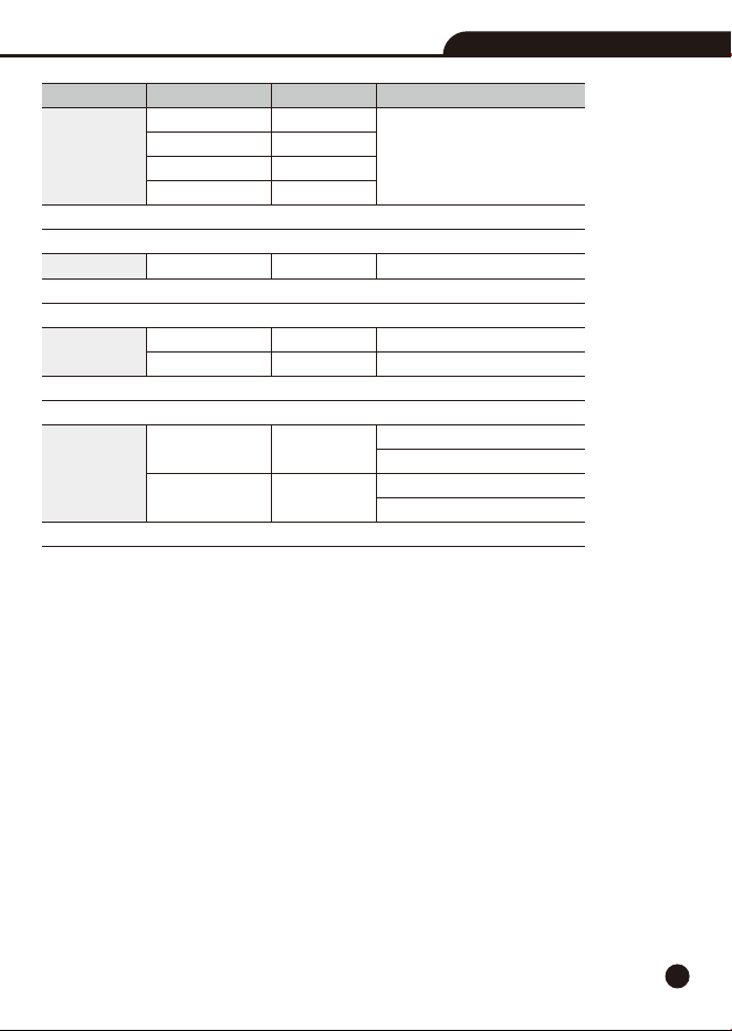
21
Range
5 to 9.999Hz
99.99Hz
999.9Hz
9.999kHz
20.0% to 80.0%
-20.0 to 1000°C
-4.0 to 1800°F
-30.0 to 350.0°C
-22.0 to 662.0°F
Accuracy
±(1.5% + 6 digits)
±(1.2% + 5 digits)
±(3% + 3°C)
±(3% + 6°F)
±3°C at -30 to 0°C
±2.0% or ±2°C at 0 to 350°C
±5°F at -22 to 32°F
±2.0% or ±4°F at 32 to 662°F
Resolution
0.001Hz
0.01Hz
0.1Hz
0.001kHz
0.1%
0.1°C
0.1°F
0.1°C
0.1°F
Function
Frequency
Sensitivity: >8Vrms
Duty Cycle
Sensitivity:>8Vrms
Type-K Temp
Probe accuracy not included.
IR Temp
D:S=4:1
Note: Accuracy is given as ±(% of reading+counts of least significant digit) at 23°C±5°C, with
relative humidity less than 80%RH. The precision index mentioned above refers to the accuracy of
40%~60% range of each measurement range. The accuracy index of the current measured outside
the measuring range increased by 1.5%, and the accuracy of other measurement functions increased
by 1%. Check waveform is sine wave. Current accuracy assessment shall be based on the position
of clamp center.
AC/DC TRMS Clamp Meter with IR Thermometer

22
6-2.General Specifications
Clamp Size
TRMS
Diode Test
Continuity Check
Low Battery Indication
Overrange Indication
Measurements Rate
Input Impedance
Display
AC Current
AC Voltage Bandwidth
Operating Temperature
Storage Temperature
Operating Humidity
Storage Humidity
Operating Altitude
Over Voltage
Battery
Auto OFF
Safety
Opening 1.3” (33mm) approx
The AC voltage and ac current of this instrument are measured by
TRMS, True RMS measurement is different from mean measurement.
The mean measurement method can only measure the symmetric
waveform, such as sine wave.
True RMS measurements can reliably measure any irregular waveform
and obtain valid values for AC voltage or AC current.
Test current of 0.3mA typical; Open circuit voltage 3.2V DC typical.
Threshold <50; Test current < 0.5mAΩ
“ ” is displayed
“OL” is displayed
2 per second, Nominal
>10M(VDC and VAC)Ω
6000 counts LCD
50 to 60Hz (AAC)
50 to 1000Hz (VAC)
5 to 40°C (41 to 104°F)
-20 to 60°C (-4 to 140°F)
Max 80% up to 31°C (87°F) decreasing linearly to 50% at 40°C (104°F)
<80%RH
2000 meters (7000ft.) maximum.
Category III 1000V, Categor IV 600V
Three “AAA” 1.5V Battery
Approx. 15minutes
For indoor use and in accordance with Overvoltage Category II, Pollution
Degree 2.
Category II includes local level, appliance, portable equipment, etc.,
with transient overvoltages less than Overvoltage CAT III.
AC/DC TRMS Clamp Meter with IR Thermometer

Rev.220923
AC/DC TRMS Clamp Meter with IR Thermometer