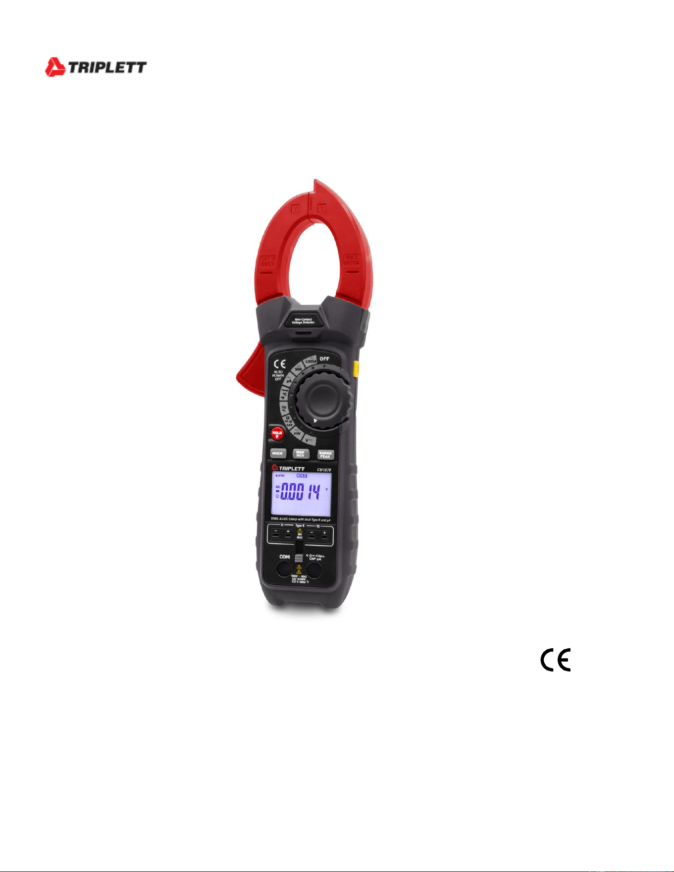
User Manual
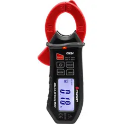
CM1070
TRMS AC/DC Clamp with Dual Type K and A

2
Introduction
Congratulations on your purchase of the CM1070 True RMS Clamp Meter. This meter
measures AC Current, DC Current, AC/DC Voltage, Resistance, Capacitance, Frequency,
Diode Test, Duty Cycle and Continuity. Special features include Dual Input Thermocouple
Temperature and Non-Contact Voltage detector. The double molded case is designed for
heavy duty use. This meter is shipped fully tested and calibrated and, with proper use, will
provide years of reliable service.
Safety
International Safety Symbols
This symbol, adjacent to another symbol or terminal, indicates the user
must refer to the manual for further information.
This symbol, adjacent to a terminal, indicates that, under normal use,
hazardous voltages may be present
Double insulation
This WARNING symbol indicates a potentially hazardous situation, which
if not avoided, could result in death or serious injury.
This CAUTION symbol indicates a potentially hazardous situation, which
if not avoided, may result damage to the product.
PER IEC1010 OVERVOLTAGE INSTALLATION CATEGORY
OVERVOLTAGE CATEGORY I
Equipment of OVERVOLTAGE CATEGORY I is equipment for connection to circuits in
which measures are taken to limit the transient overvoltages to an appropriate low level.
Note – Examples include protected electronic circuits.
OVERVOLTAGE CATEGORY II
Equipment of OVERVOLTAGE CATEGORY II is energy-consuming equipment to be
supplied from the fixed installation.
Note – Examples include household, office, and laboratory appliances.
OVERVOLTAGE CATEGORY III
Equipment of OVERVOLTAGE CATEGORY III is equipment in fixed installations.
Note – Examples include switches in the fixed installation and some equipment for industrial
use with permanent connection to the fixed installation.
OVERVOLTAGE CATEGORY IV
Equipment of OVERVOLTAGE CATEGORY IV is for use at the origin of the installation.
Note – Examples include electricity meters and primary over-current protection equipment.
WARNING
CAUTION

3
SAFETY NOTES
• Do not exceed the maximum allowable input range of any function.
• Do not apply voltage to meter when resistance function is selected.
• Set the function switch OFF when the meter is not in use.
• Remove the battery if meter is to be stored for longer than 60 days.
WARNINGS
• Set function switch to the appropriate position before measuring.
• When measuring volts do not switch to current/resistance modes.
• Do not measure current on a circuit whose voltage exceeds 600V.
• When changing ranges always disconnect the test leads from the circuit under test.
CAUTIONS
• Improper use of this meter can cause damage, shock, injury or death. Read and
understand this user manual before operating the meter.
• Always remove the test leads before replacing the battery or fuses.
• Inspect the condition of the test leads and the meter itself for any damage before
operating the meter. Repair or replace any damage before use.
• Use great care when making measurements if the voltages are greater than 25VAC
rms or 35VDC. These voltages are considered a shock hazard.
• Always discharge capacitors and remove power from the device under test before
performing Diode, Resistance or Continuity tests.
• Voltage checks on electrical outlets can be difficult and misleading because of the
uncertainty of connection to the recessed electrical contacts. Other means should be
used to ensure that the terminals are not "live".
• If the equipment is used in a manner not specified by the manufacturer, the protection
provided by the equipment may be impaired.
• This device is not a toy and must not reach children’s hands. It contains hazardous
objects as well as small parts that the children could swallow. In case a child
swallows any of them, please contact a physician immediately.
• Do not leave batteries and packing material lying around unattended; they can be
dangerous for children if they use them as toys.
• In case the device is going to be unused for an extended period of time, remove the
batteries to prevent them from draining.
• Expired or damaged batteries can cause cauterization on contact with the skin.
Always, therefore, use suitable hand gloves in such cases
• See that the batteries are not short-circuited. Do not throw batteries into the fire.
• Do not directly view or direct the laser pointer at an eye. Low power visible lasers
do not normally present a hazard but may present some potential for hazard if viewed
directly for extended periods of time.
Function
Maximum Input
A AC,
1000A AC
V DC, V AC
600V DC/AC
Resistance, Capacitance, Frequency, Diode Test
250V DC/AC
A
4000 A
Type K Temperature
30V DC, 24V AC
4
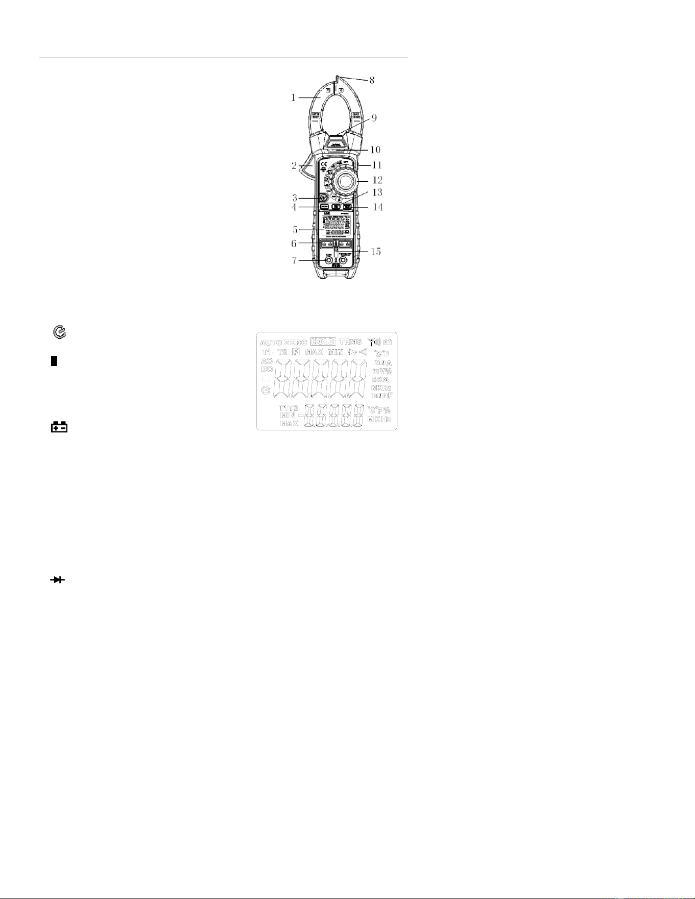
Description
Meter Description
1. Current clamp
2. Clamp opening trigger
3. HOLD/BACKLIGHT button
4. MODE /
o
C/
o
F
5. Backlit LCD Display
6. Type K input jacks
7. Multimeter input jacks
8. Non-Contact Voltage Detector
9. LAMP
10. NCV LED indicator
11. LAMP/ZERO button
12. Function switch
13. MAX/MIN button
14. RANGE/PEAK / Thermocouple display button
15. Input shutter
Display icons Description
HOLD Data Hold
Auto Power Off
AUTO Autoranging
P Peak Hold
DC Direct Current
AC Alternating Current
MAX Max reading
MIN Min reading
Low battery
ZERO DCA or CAP zero
mV or V Milli-volts or Volts (Voltage)
Ohms (Resistance)
A Amperes (Current)
F Farad (Capacitance)
Hz Hertz (Frequency)
% Duty Ratio
o
F and
o
C Fahrenheit and Celsius units (Temperature)
T1, T2, T1-T2 Therocouple 1, Thermocouple 2, Thermocouple difference
n, m, , M, k Unit of measure prefixes: nano, milli, micro, mega, and kilo
•
)
)
) Continuity test
Diode test
5
Operation
NOTES: Read and understand all Warning and Caution statements in this operation
manual prior to using this meter. Set the function select switch to the OFF position when
the meter is not in use.
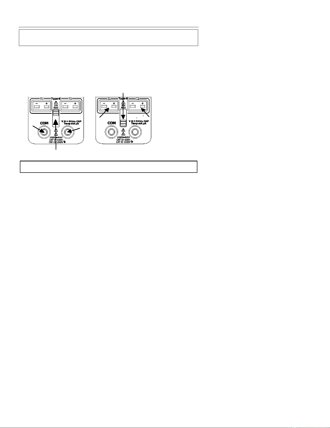
Input Shutter
The Input Shutter inhibits simultaneous connection to the thermocouple jacks and the
DMM input jacks. This is a safety feature which prevents a potentially hazardous condition
from existing during high voltage measurements. Slide the shutter up for test lead
measurements or slide it down for thermocouple temperature measurements.
Non-Contact Voltage Detector
WARNING: Risk of Electrocution. Before use, always test the Voltage Detector on a
known live circuit to verify proper operation.
1. Rotate the Function switch to any measurement position.
2. Place the detector probe tip on the conductor to be tested.
3. If AC voltage is present, the NCV detector light will turn on with a steady red light.
NOTE: The conductors in electrical cord sets are often twisted. For best results, move the
probe tip along a length of the cord to assure placing the tip near the live
conductor.
NOTE: The detector is designed with high sensitivity. Static electricity or other sources of
energy may randomly trip the sensor. This is normal operation.
6
AC/DC Current Measurements
WARNING: Disconnect the test leads before making clamp measurements.
1. Rotate the Function switch to the 1000AAC/DC
position
2. Press the MODE button to select AC or DC.
3. Press the trigger to open jaw. Fully enclose only
one conductor.
4. Read the current value in the display.
5. If the value is less than 50A, rotate the function
switch to the 50AAC/DC position to improve
resolution.
DCA Zero
The Zero feature removes offset values and improves accuracy for DC current
measurements. To perform a zero, select ADC and, with no conductor in the jaw, press
and hold the MODE ZERO button for two beeps. The display will zero. The offset value
is now stored and removed from all measurements.
Frequency
When ACV is selected, the measured frequency can be viewed in the lower display.
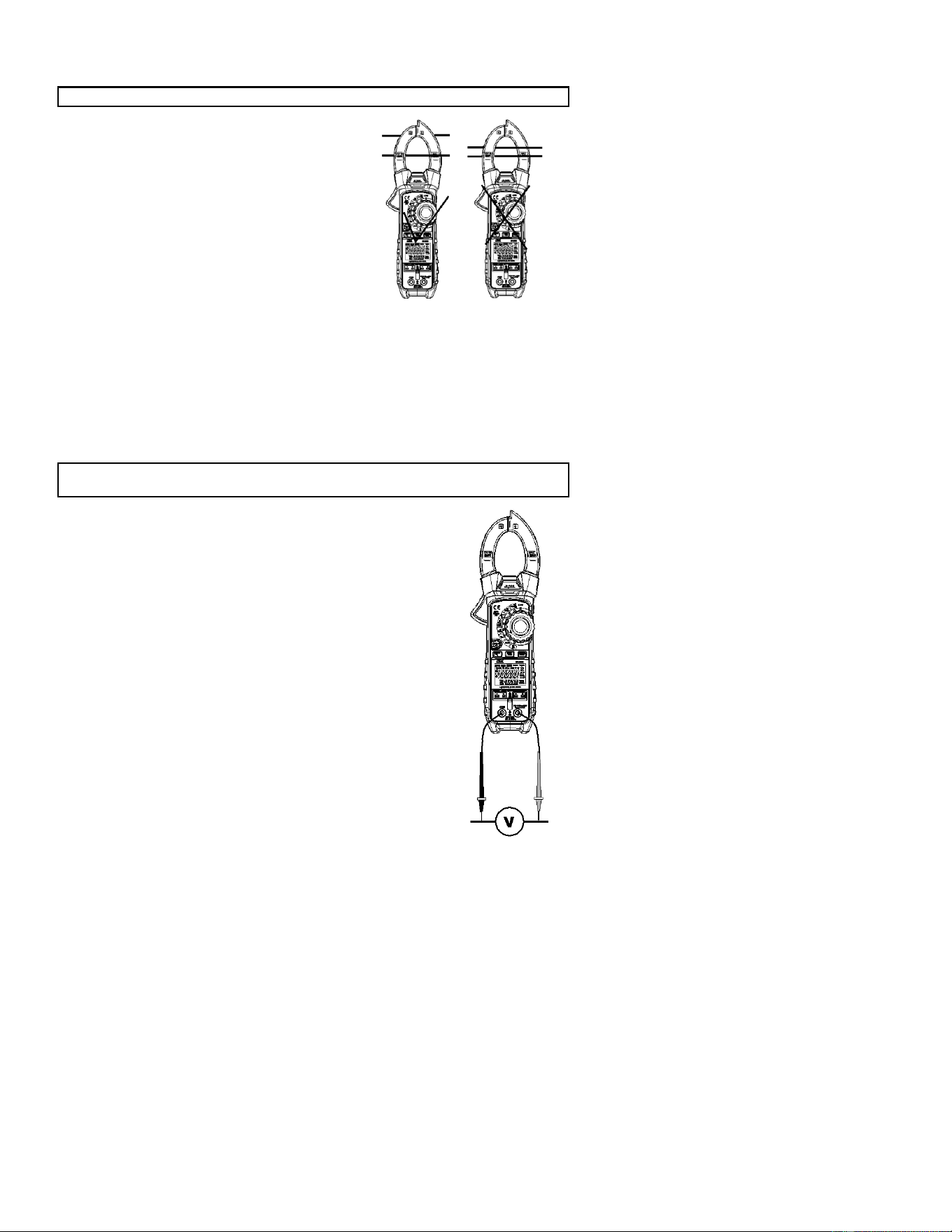
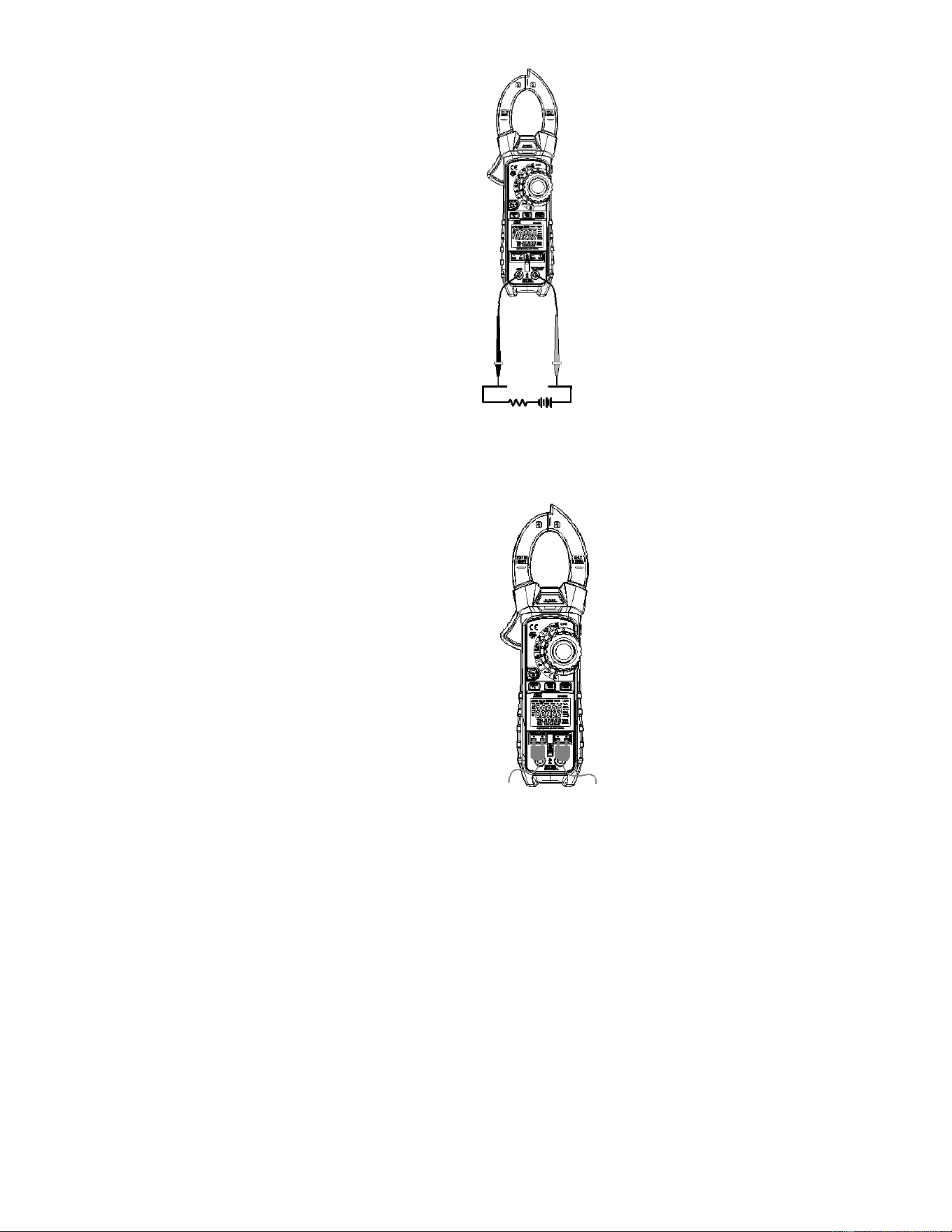
AC/DC Voltage Measurements
CAUTION: Do not measure voltages if a motor on the circuit is being switched ON or
OFF. Large voltage surges may occur that can damage the meter.
1. Slide the input shutter to the up position.
2. Rotate the function switch to the V position.
3. Press the MODE button to select AC or DC Voltage.
4. Insert the black test lead banana plug into the negative COM
jack.
Insert the red test lead banana plug into the positive V jack.
5. Touch the black test probe tip to the negative side of the circuit.
Touch the red test probe tip to the positive side of the circuit.
6. Read the voltage value in the display.
Frequency
When ACA is selected, the measured frequency can be viewed in th
e
lower display.
7
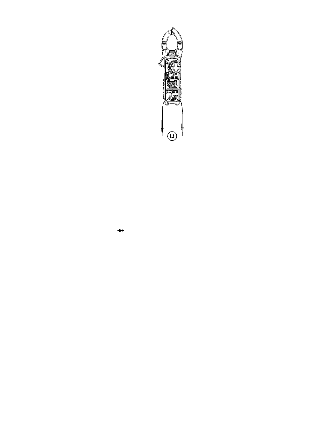
Resistance Measurements
Note: Remove power from the device under test before making
resistance measurements
1. Slide the input shutter to the up position.
2. Set the function switch to the position.
3. Insert the black test lead banana plug into the negative COM
jack.
Insert the red test lead banana plug into the positive V jack.
4. Touch the black test probe tip to one side of the device.
Touch the red test probe tip to the other side of the device.
5. Read the resistance value in the display.
Continuity Test
1. Connect as described for resistance measurements.
2. Press the MODE button to select continuity•
)
)
).
3. Touch the test probe tips across the circuit or component
under test.
4. If the resistance is < 50, a tone will sound.
Diode Test
1. Connect as described for resistance measurements
2. Press the MODE button to select diode test .
3. Touch the test probe tips to the diode or semiconductor junction under test. Note the
meter reading.
4. Reverse the test lead polarity by reversing the red and black leads. Note this reading.
5. The diode or junction can be evaluated as follows:
▪ If one reading displays a value (typically 0.400V to 01.800V) and the other
reading displays OL, the diode is good.
▪ If both readings display OL the device is open.
▪ If both readings are very small or ‘0’, the device is shorted.
8
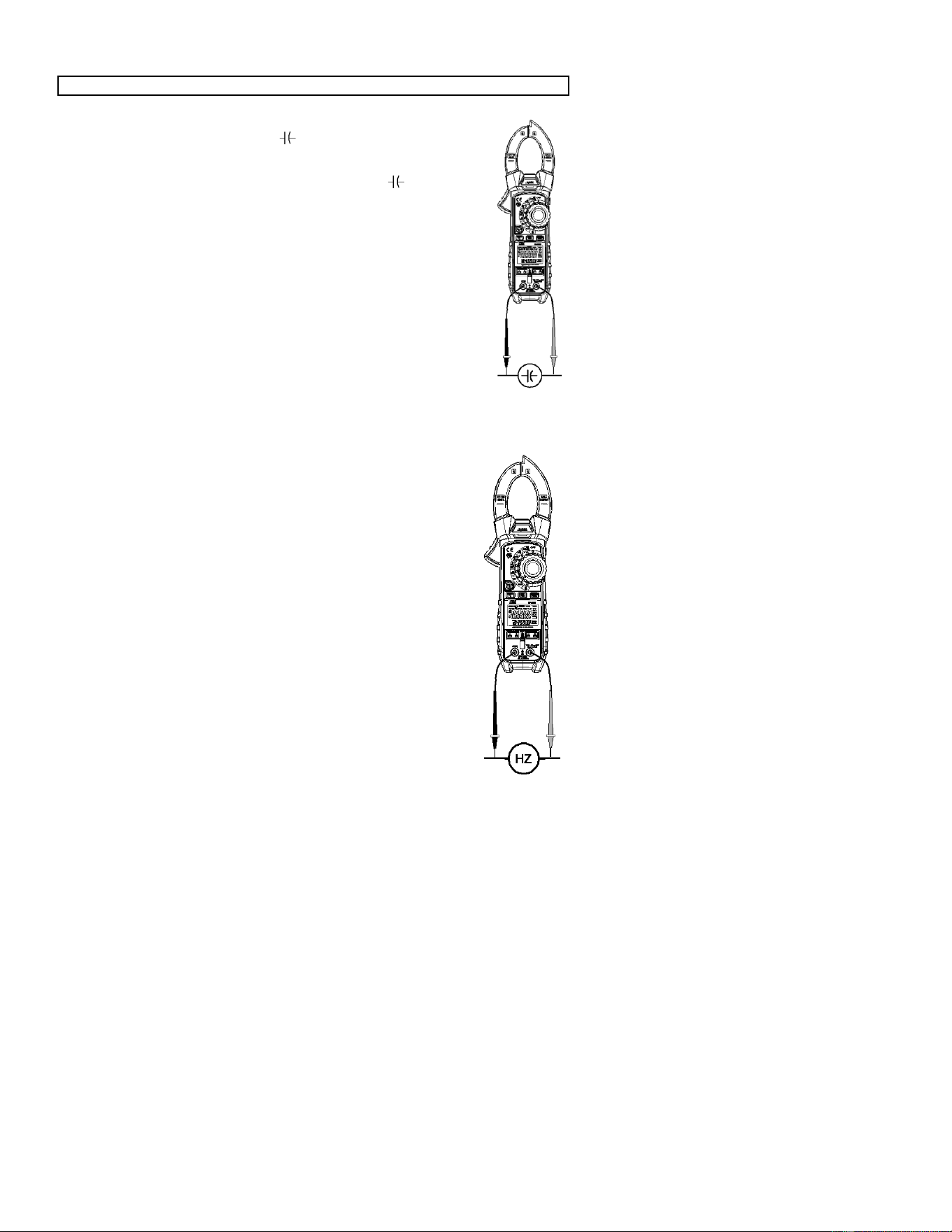
Capacitance Measurements
WARNING: To avoid electric shock, discharge the capacitor before measuring.
1. Slide the input shutter to the up position.
2. Rotate the function switch to the capacitance position.
3. Insert the black test lead banana plug into the negative COM jack.
Insert the red test lead banana plug into the positive jack.
4. Touch the black test probe tip to one side of the device.
Touch the red test probe tip to the other side of the device.
5. Read the capacitance value in the display.
Note: For very large values of capacitance measurement time can be
several seconds before the final reading stabilizes.
Note: The Zero feature removes stray test lead capacitance to improve
the accuracy of low value capacitance measurements. To perform a
zero, Press and hold the MODE ZERO button for two beeps. The
display will zero. The offset value is now stored and is removed
from all measurements.
.
Frequency and Duty Ratio Measurements
1. Slide the input shutter to the up position.
2. Rotate the function switch to the Hz % Position.
3. Insert the black test lead banana plug into the negative COM jack.
Insert the red test lead banana plug into the positive Hz jack.
4. Touch the black test probe tip to one side of the device.
Touch the red test probe tip to the other side of the device.
5. Read the Frequency value on the upper large display.
Read the Duty Ratio on the lower small display.
6. Press the MODE button to display the Duty Ratio on the large
display.
9
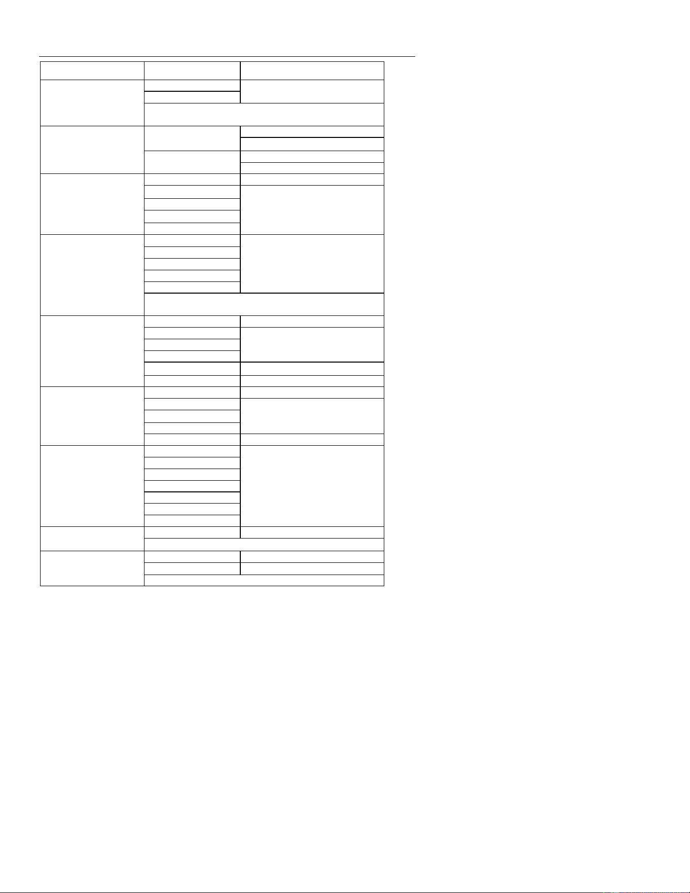
A DC/AC Current Measurements
1. Slide the input shutter to the up position.
2. Rotate the function switch to the A position.
3. Press the MODE button to select AC or DC.
4. Insert the black test lead banana plug into the negative COM jack.
Insert the red test lead banana plug into the positive A jack.
5. Turn power to the circuit under test off and make a break in the
circuit.
6. Insert the meter in series with the circuit;
Touch the black test probe tip to the negative side of the break.
Touch the red test probe tip to the positive side of the break.
7. Turn circuit power on.
8. Read the current value in the display.
Type K Temperature Measurements
1. Slide the input shutter to the down position.
2. Rotate the function switch to the TYPE K temperature position.
3. Press the MODE button to select °F or °C.
4. Insert the Temperature Probe(s) into the T1 and/or T2 type k
sockets.
5. Place the temperature probe tip(s) where needed.
6. Read the temperature on the display.
7. Press the T1-T2 button to step through the display combinations:
Upper display Lower display
a. T1 T2
b. T2 T1
c. T1-T2 T1
d. T1- T2 T2
Note: In case of an open input or a temperature overrange, the meter will
display “- - - -” .

10

11
Data Hold
To freeze the LCD reading, press the HOLD button. While data hold is active, the HOLD
icon appears on the LCD. Press the HOLD button again to return to normal operation.
MAX/MIN
1. Press the MAX/MIN button to activate the MAX/MIN recording mode. The display icon
"MAX" will appear. The meter will begins recording and displaying the maximum
value measured.
2. Press the MAX/MIN button and “MIN” will appear. The meter will display the minimum
value measured during the recording session.
3. Press the MAX/MIN button and “MAX MIN” will appear. The meter will display the
present reading, but will continue to update and store the max and min readings.
4. To exit MAX/MIN mode press and hold the MAX/MIN button for 2 seconds.
Peak Hold
When ACA or ACV is selected, press and hold PEAK button 2 seconds enables the peak
capture circuit. The meter will now capture and display the maximum and minimum peaks
of the waveform.
To exit Peak Hold mode press and hold the Peak Hold button for 2 seconds.
RANGE
In the Voltage, Resistance, Capacitance, Frequency or uA function the meter automatically
selects the best range for the measurements being made. For measurement situations
requiring that a range be manually selected, perform the following:
1. Press the RANGE button. The “AUTO” display icon will turn off.
2. Press the RANGE key to step through the available ranges. Observe the decimal
point and units displayed until the preferred range is located.
3. To exit the Manual Ranging mode and return to Autoranging, press and hold the
RANGE key for 2 seconds.
LCD Backlight
The LCD is equipped with backlighting for easier viewing, especially in dimly lit areas.
Press and hold the HOLD/ button for 2 seconds to turn the backlight on. The backlight
will automatically turn off after 30 seconds.
LAMP ON/OFF
Press and hold the
ZERO
button for 2 seconds to turn on/off the lamp.
Automatic Power OFF with Disable
In order to conserve battery life, the meter will automatically turn off after approximately 30
minutes. To turn the meter on again, turn the function switch to the OFF position and then
to the desired function position.
To disable APO:
1. From the OFF position, hold the MODE button and rotate the FUNCTION switch to a
measurement function.
2. will appear in the display
3. Release the MODE button

12
4. APO is now disabled (APO icon is off) and will be reset when the Function switch is
returned to the OFF position.
Low battery indication
When the icon appears in the display, the battery should be replaced. Refer to the
battery replacement procedure in the maintenance section.

13
Maintenance
WARNING: To avoid electrical shock, disconnect the meter from any circuit, remove the
test leads from the input terminals, and turn OFF the meter before opening the case. Do
not operate the meter with an open case.
Cleaning and Storage
Periodically wipe the case with a damp cloth and mild detergent; do not use abrasives or
solvents. If the meter is not to be used for 60 days or more, remove the battery and store it
separately.
Battery Replacement
1. Remove the Phillips head screw that secures the rear battery door
2. Open the battery compartment
3. Replace the 9V battery
4. Secure the battery compartment door
5.
You, as the end user, are legally bound (Battery ordinance) to return all used
batteries and accumulators; disposal in the household garbage is prohibited!
You can hand over your used batteries / accumulators, gratuitously, at the
collection points for our branches in your community or wherever batteries /
accumulators are sold!
Disposal
Follow the valid legal stipulations in respect of the disposal of the device at the
end of its lifecycle
Fuse Replacement
1. Remove the battery
2. Remove the Phillips head screws (2) that secures the rear cover.
3. Replace the fuse with one of equal rating. (500mA, 660V fast blow [SIBA 70-180-40])
4. Replace the rear cover and battery
14
Specifications
Function
Range& Resolution
Accuracy (% of reading)
AC Current
True RMS (50Hz to 60
Hz)
50.00 AAC
± (2.5% +5digits)
1000.0 AAC
All AC Current ranges are specified from 5% of range to
100% of range
uA Current
500.00uA
DC: ±(1.0% + 6 digits)
AC: ±(1.5% + 30 digits)
5000.0uA
DC: ±(1.0% + 6 digits)
AC: ±(1.5% + 30 digits)
DC Voltage
500.00 mVDC
± (1.0% + 8 digits)
5.0000VDC
± (0.1% + 4 digits)
50.000 VDC
500. 00 VDC
600.0 VDC
AC
Voltage True RMS (50 Hz
to 1000 Hz)
500.00 mVAC
± (1.0% + 30 digits)
5.0000 VAC
50.000 VAC
500. 00 VAC
0600.0 VAC
All AC voltage ranges are specified from 5% of range to 100%
of range
Resistance
500.00 Ω
± (1.0% + 9 digits)
5.0000KΩ
± (1.0% + 5 digits)
50.000KΩ
500.00KΩ
5.0000MΩ
± (2.0% + 10digits)
50.000MΩ
± (3.0% + 10 digits)
Capacitance
500.00nF
±(3.5% reading + 40digits)
5000.0nF
±(3.5% reading + 10digits)
50.00.μF
500.0.μF
5.000mF
±(5% reading + 10 digits)
Frequency
50Hz
±(0.3% reading + 2 digits)
500Hz
5KHz
50KHz
500KHz
5MHz
10MHz
Duty Cycle
5.0 to 95.0%
± (1.0% reading + 2 digits)
Pulse width: 100µs - 100ms, Frequency: 10Hz to 10kHz
Temp(type-K)
(probe accuracy not
included)
-100.0 to 1000.0°C
±(1.0% reading + 2.5 °C)
-148.0 to 1832.0°F
±(1.0% reading + 4.5°F)
(probe accuracy not included)

15
General Specifications
Clamp jaw opening 1.9" (48mm) approx.
Display Dual 50,000/50,000 count backlit LCD
Continuity check Threshold 50; Test current < 0.5mA
Diode test Test current of 0.3mA typical;
Open circuit voltage 2.8VDC typical
Low Battery indication Battery symbol is displayed
Over-range indication ‘OL’ display
Measurement rate 2 readings per second, nominal
Peak detector >1ms
Thermocouple sensor Type K thermocouple required
Fuse 500mA, ceramic fast blow
Input Impedance 10M (VDC and VAC)
AC bandwidth 50 to 400Hz (AAC and VAC)
AC response True rms (AAC and VAC)
Crest Factor 3.0 in 40A and 400A ranges, 1.4 in 1000A range (50/60Hz
and 5% to 100% of range)
Operating Temperature 5C to 40C (41F to 104F)
Storage Temperature -20C to 60C (-4F to 140F)
Operating Humidity Max 80% up to 31C (87F) decreasing linearly to 50% at
40C (104F)
Storage Humidity <80%
Operating Altitude 7000ft. (2000meters) maximum.
Battery One (1) 9V Battery (NEDA 1604)
Auto power OFF After approx. 30 minutes, with disable
Dimensions & Weight 9.1x3.0x1.6” (230x76x40mm); 11.1 oz. (315g)
Safety For indoor use and in accordance with the requirements for
double insulation to IEC1010-1 (2001): EN61010-1 (2001)
Overvoltage Category III 600V and Category II 1000V,
Pollution Degree 2.
Approvals CE
Warranty
Triplett / Jewell Instruments extends the following warranty to the original purchaser of these
goods for use. Triplett warrants to the original purchaser for use that the products sold by it
will be free from defects in workmanship and material for a period of (1) one year from the
date of purchase. This warranty does not apply to any of our products which have been
repaired or altered by unauthorized persons in any way or purchased from unauthorized
distributors so as, in our sole judgment, to injure their stability or reliability, or which have
been subject to misuse, abuse, misapplication, negligence, accident or which have had the
serial numbers altered, defaced, or removed. Accessories, including batteries are not
covered by this warranty.
Copyright © 2023 Triplett
www.triplett.com

16