

Table of Contents
Installation_Guide
............................................................................................................
2
Contents
.............................................................................................................................
3
Installation Guide
............................................................................................................
4
About this guide
........................................................................................................
4
Install SIP SERVER
...................................................................................................
13
DS-KS6150
.............................................................................................................
5
DS-KS6160
.............................................................................................................
7
DS-KS6170
.............................................................................................................
9
Expansion Board
.................................................................................................
12
Installation Warnings
.......................................................................................
13
Install DS-KS6160/DS-KS6170
...................................................................................
14
Getting Started
...............................................................................................................
21
Initial Setup Using the Installation Wizard
..............................................................
26
Change the Password of Super Administrator
................................................................
30
Reset the Password of Super Administrator
.................................................................
31
Set up Company Information
............................................................................................
32
View System Information
.................................................................................................
33

Installation Guide
Installation Guide for SIP SERVER
About this guide
This guide describes hardware ports and indicators on the SIP SERVER, and give instructions
on how to install the SIP SERVER and telephony modules.
Warning:
This equipment is not suitable for use in locations where children are likely to be present.
CAUTlON: Risk of explosion if the battery is replaced by an incorrect type.
Do not ingest battery. Chemical Burn Hazard!
This product contains a coin/button cell battery. lf the coin/button cell battery is
swallowed, itcan cause severe internal burns in just 2 hours and can lead to death.
Improper replacement of the battery with an incorrect type may defeat a safeguard (for
example, in the case of some lithium battery types).
Do not dispose of the battery into fire or a hot oven, or mechanically crush or cut the
battery,which may result in an explosion.
Do not leave the battery in an extremely high temperature surrounding environment,
which may result in an explosion or the leakage of flammable liquid or gas.
Do not subject the battery to extremely low air pressure, which may result in an explosion
or the leakage of flammable liquid or gas.
Dispose of used batteries according to the instructions.
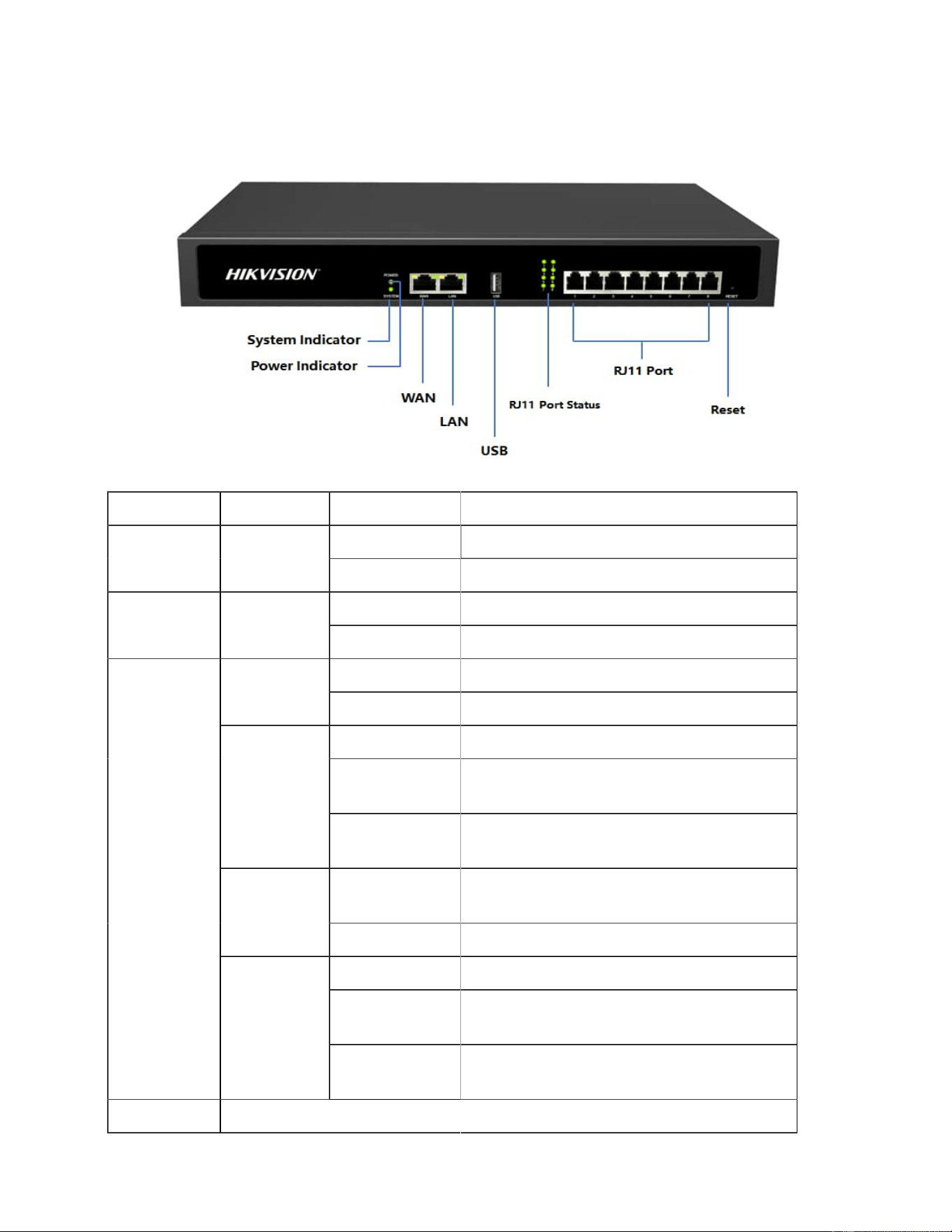
Table . Descriptions of DS-KS6150 Front Panel
LED Indication Status Description
On The power is switched on.POWER Power sta
tus
Off The power is switched off.
The system is running properly.SYSTEM System sta Blinking
tus
Static/Off The system goes wrong.
Green: static The analog phone is idle.FXS
Green: blinking The analog phone is busy.
Red: static The GSM/4G Trunk is idle.
Red: blinking
slowly
No SIM card.
GSM/4G
Red: blinking
rapidly
The GSM/3G/4G trunk is in use.
ing
Orange: blink The BRI line is disconnected.BRI
Orange: static The BRI line is connected or in use.
Red: static The PSTN line is idle.
Red: blinking
slowly
No PSTN line is connected to the FXO
port.
1-8 LED
(RJ11 port
status)
FXO
Red: blinking
rapidly
The PSTN line is busy.
Port Description
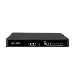
DS-KS6150
Overview Front Panel
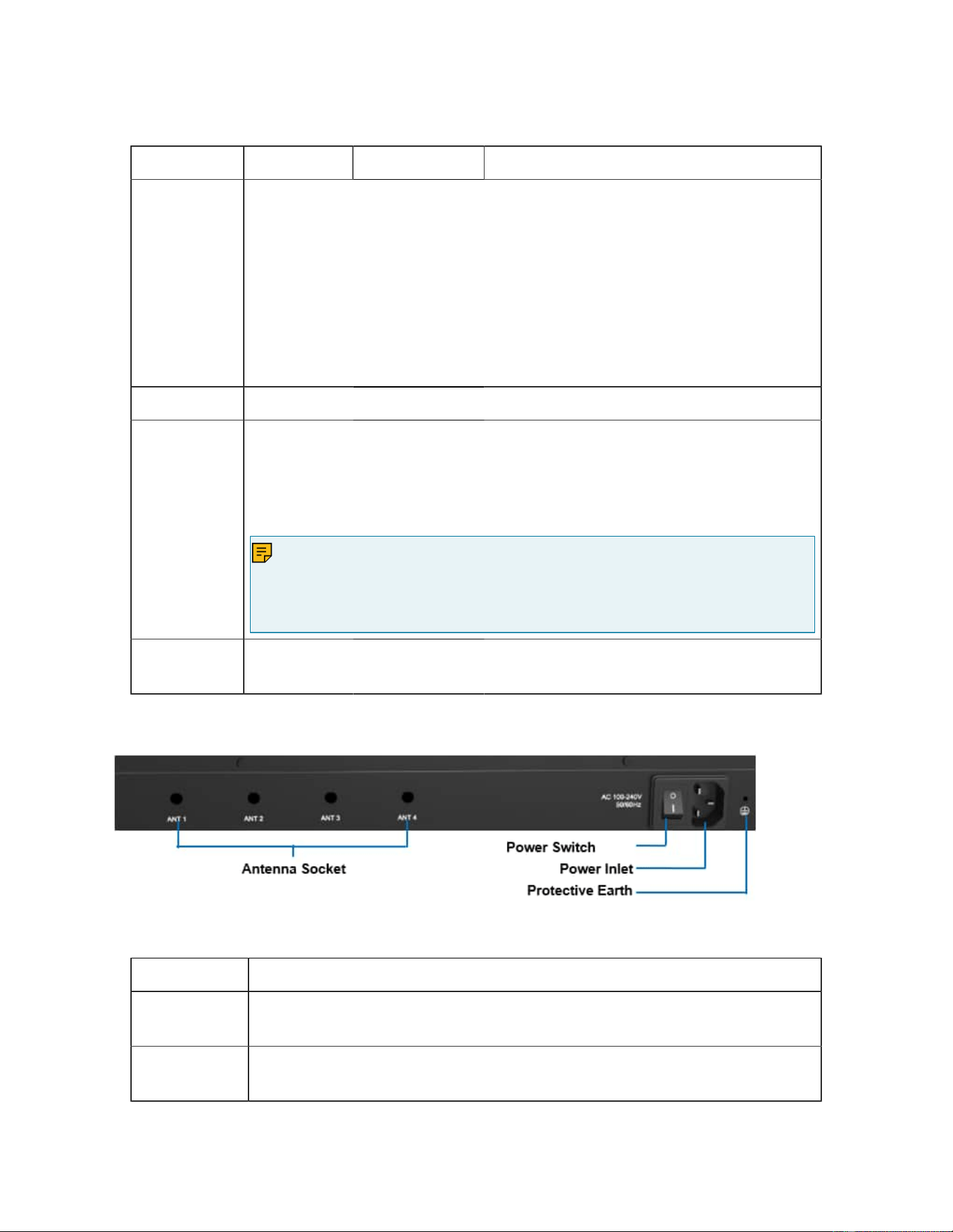
Table . Descriptions of DS-KS6150 Front Panel (continued)
LED Indication Status Description
WAN/LAN DS-KS6150 provides two 10/100/1000Mbps adaptive RJ45 Ethernet
ports, and supports 3 Ethernet modes. The default mode is “Single”.
• Single: LAN port will be used for uplink connection. WAN port is
disabled.
• Bridge: LAN port will be used for uplink connection. WAN port will
be used as bridge for PC connection.
• Dual: Both LAN and WAN ports can be used for uplink connec
tion.
USB Insert USB to store auto recording files.
1-8 Port
(RJ11 port)
• FXO port(red light): For the connection of PSTN lines or FXS ports
of traditional SIP SERVER.
• FXS port (green light): For the connection of analog phones.
• BRI port (orange light): For the connection of ISDN BRI lines.
Note:
The sequence number of the ports corresponds to that of the Indicator
lights in the front panel. (I.e. the LED lights in the front indicate the con
nection status of the corresponding ports at the back panel.)
Reset but
ton
Press and hold for 10 seconds to restore the factory defaults.
Rear Panel
Table 8. Descriptions of DS-KS6150 Rear Panel
Port Description
Antenna
Socket
Rotate the antenna into the Antenna Socket.
Power
Switch
Press this button to switch on/off the device.
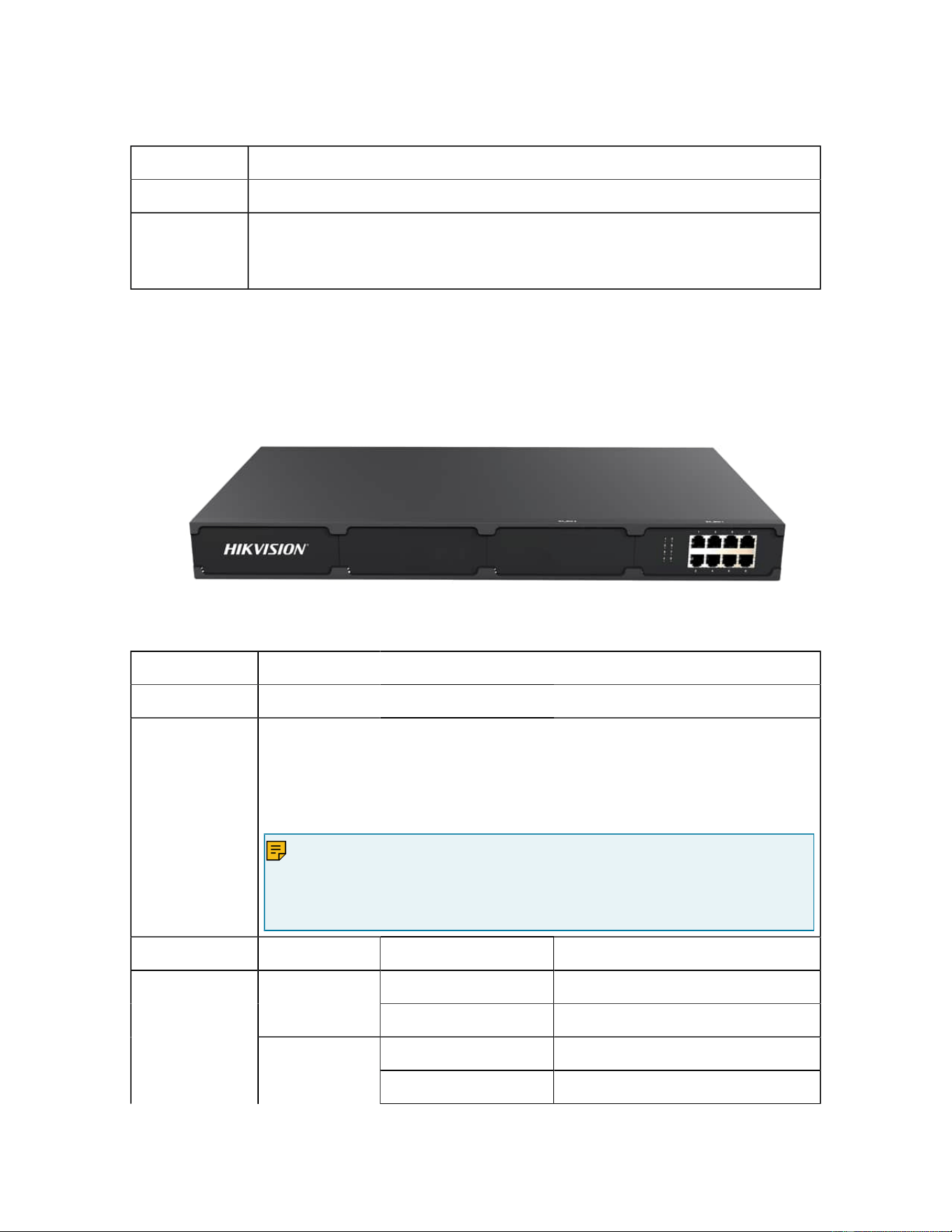
Table 8. Descriptions of DS-KS6150 Rear Panel (continued)
Port Description
Power Inlet Connect the supplied power supply to the port.
Protective
Earth
Connect to the ground to reduce the risk of electrocution to the user or
protect the PBX from the bad effects of external noise in the case of a
lightning strike.
DS-KS6160 Overview
Front Panel
Table 9. Descriptions of DS-KS6160 Front Panel
Port Description
E1/T1 Connect the E1/T1 line.
1-8 Port
(RJ11 port)
• FXO port (red light): For the connection of PSTN lines or FXS
ports of traditional PBX.
• FXS port (green light): For the connection of analog phones.
• BRI port (orange light): For the connection of ISDN BRI lines.
Note:
The sequence number of the ports corresponds to that of the Indica
tor lights in the front panel. (I.e. the LED lights in the front indicate the
connection status of the corresponding ports at the back panel.)
LED Indication Status Description
Green: static The analog phone is idle.FXS
Green: blinking The analog phone is busy.
Red: static The GSM/3G/4G Trunk is idle.
1-8
(RJ11 port
status)
GSM/3G/4G
Red: blinking slowly No SIM card.
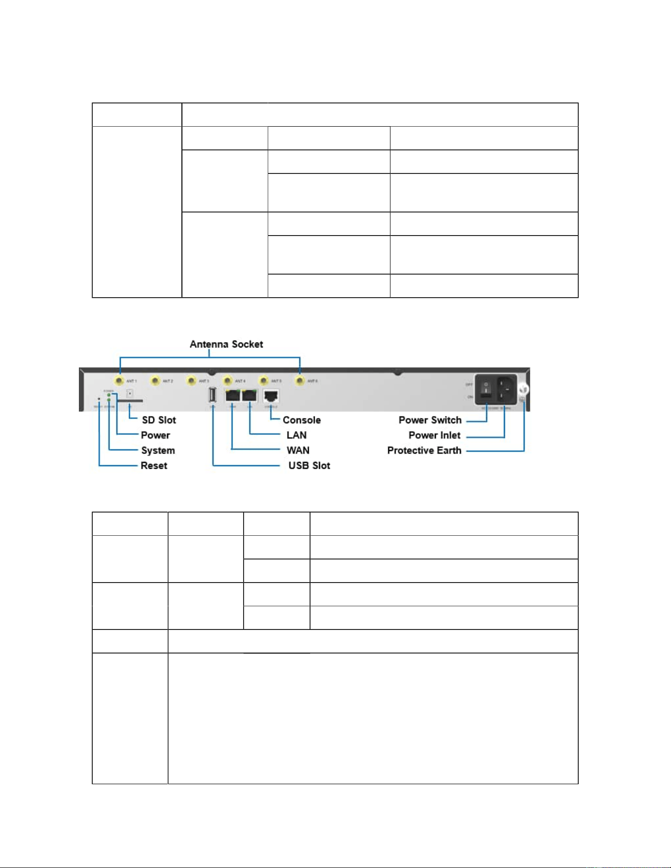
Table 9. Descriptions of DS-KS6160 Front Panel (continued)
Port Description
Red: blinking rapidly The GSM/3G/4G trunk is in use.
Orange: blinking The BRI line is disconnected.BRI
Orange: static The BRI line is connected or in
use.
Red: static The PSTN line is idle.
Red: blinking slowly No PSTN line is connected to
the FXO port.
FXO
Red: blinking rapidly The PSTN line is busy.
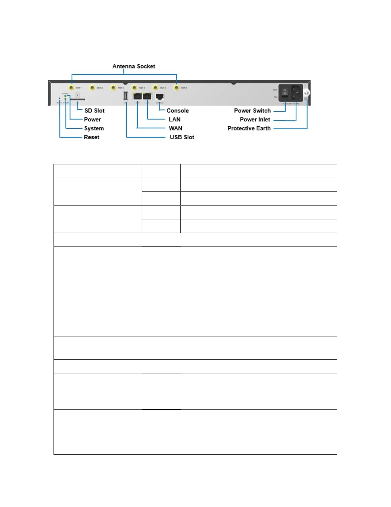
Rear Panel
Table 10. Descriptions of DS-KS6160 Rear Panel
LED Indication Status Description
On The power is switched on.POWER Power sta
tus
Off The power is switched off.
Blinking The system is running properly.SYSTEM System sta
tus
Static/Off The system goes wrong.
Port Description
WAN/LAN DS-KS6160 provides two 10/100/1000Mbps adaptive RJ45 Ethernet
ports, and supports 3 Ethernet modes. The default mode is “Single”.
• Single: LAN port will be used for uplink connection. WAN port is
disabled.
• Bridge: LAN port will be used for uplink connection. WAN port will
be used as bridge for PC connection.
• Dual: Both LAN and WAN ports can be used for uplink connection.
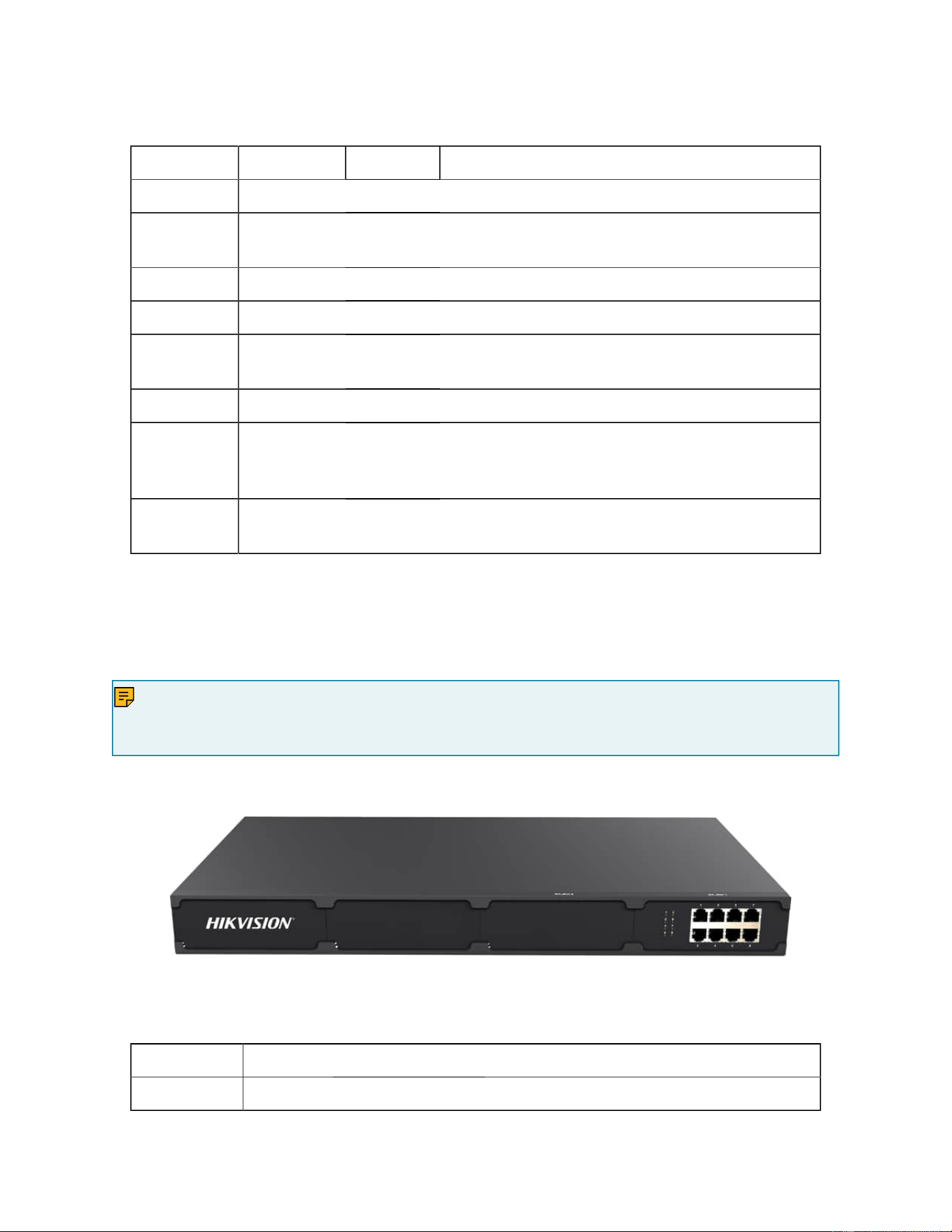
Table 10. Descriptions of DS-KS6160 Rear Panel (continued)
LED Indication Status Description
SD Insert SD card to store auto recording files.
butReset
ton
Press and hold for 10 seconds to restore the factory defaults.
USB Insert USB device to store auto recording files.
Console Connect RS232 line to debug the system.
Power
Switch
Press this button to switch on/off the device.
Power Inlet Connect the supplied power supply to the port.
Protective
Earth
Connect to the ground to reduce the risk of electrocution to the user or
protect the PBX from the bad effects of external noise in the case of a
lightning strike.
Antenna
Socket
Rotate the antenna into the Antenna Socket.
DS-KS6170 Overview
Front Panel (1*DS-KSMET08 )
Note:
Table
DS-KS6170 only supports 2 expansion boards. You can install DS-KSMET08 board or DS-
KSMETE1 board according to your needs.
11. Descriptions of DS-KS6170 Front Panel
Port Description
E1/T1 Connect the E1/T1 line.
Table 11. Descriptions of DS-KS6170 Front Panel (continued)
Port Description
1-8 Port
(RJ11 port)
• FXO port (red light): For the connection of PSTN lines or FXS
ports of traditional DS-KS6170.
• FXS port (green light): For the connection of analog phones.
• BRI port (orange light): For the connection of ISDN BRI lines.
Note:
The sequence number of the ports corresponds to that of the Indicator
lights in the front panel. (I.e. the LED lights in the front indicate the con
nection status of the corresponding ports at the back panel.)
LED Indica
tion
Status Description
Green: static The analog phone is idle.FXS
Green: blinking The analog phone is busy.
ed: static The GSM/3G/4G Trunk is idle.
Red: blinking
slowly
No SIM card.
GSM/3
G/4G
Red: blinking
rapidly
The GSM/3G/4G trunk is in use.
Orange: blinking The BRI line is disconnected.BRI
Orange: static The BRI line is connected or in use.
Red: static The PSTN line is idle.
Red: blinking
slowly
No PSTN line is connected to the FXO
port.
1-8
(RJ11 port
status)
FXO
Red: blinking
rapidly
The PSTN line is busy.
Rear Panel
Table 12. Descriptions of DS-KS6170 Rear Panel
LED Indication Status Description
On The power is switched on.POWER Power sta
tus
Off The power is switched off.
Blinking The system is running properly.SYSTEM System sta
tus
Static/Off The system goes wrong.
Port Description
WAN/LAN Yeastar S300 provides two 10/100/1000Mbps adaptive RJ45 Ethernet
ports, and supports 3 Ethernet modes. The default mode is “Single”.
• Single: LAN port will be used for uplink connection. WAN port is
disabled.
• Bridge: LAN port will be used for uplink connection. WAN port will
be used as bridge for PC connection.
• Dual: Both LAN and WAN ports can be used for uplink connection.
SD Insert SD card to store auto recording files.
Reset but
ton
Press and hold for 10 seconds to restore the factory defaults.
USB Insert USB device to store auto recording files.
Console Connect RS232 line to debug the system.
Power
Switch
Press this button to switch on/off the device.
Power Inlet Connect the supplied power supply to the port.
Protective
Earth
Connect to the ground to reduce the risk of electrocution to the user or
protect the PBX from the bad effects of external noise in the case of a
lightning strike.
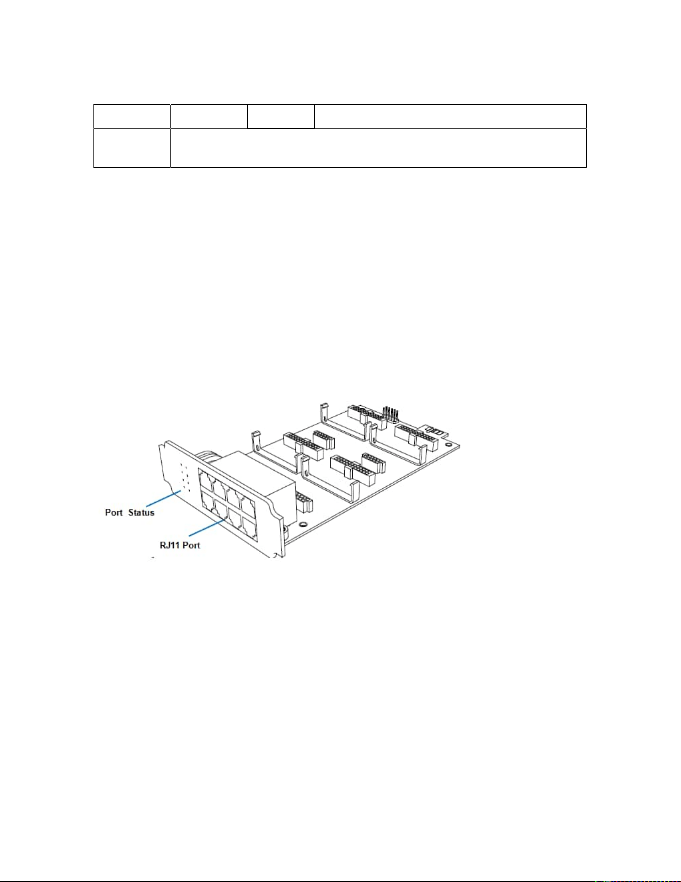
Table 12. Descriptions of DS-KS6170 Rear Panel (continued)
LED Indication Status Description
Antenna
Socket
Rotate the antenna into the Antenna Socket.
Expansion Board
DS-KS6170 and DS-KS6160 are expandable.
DS-KSMETE1 Expansion Board
• DS-KS6160 supports up to 1 DS-KSMET08 /DS-KSMETE1 Expansion Boards; supports 1 DS-KSME100
Module.
• DS-KS6170supports up to 2 DS-KSMET08 /DS-KSMETE1 Expansion Boards; supports up to 2 DS-
KSME100 Modules.
DS-KSMETE1 board supports up to 4 modules (8 RJ11 ports).
• DS-KSMXO2 Module
• DS-KSMXS2 Module
• DS-KSMXOS2 Module
• DS-KSMXB2 Module
• DS-KSM4G Module
Optional modules on DS-KSMET08 board
DS-KSMGSM Module
DS-KSMETE1 Expansion Board
DS-KSMETE1 board supports 1 E1/T1 port.
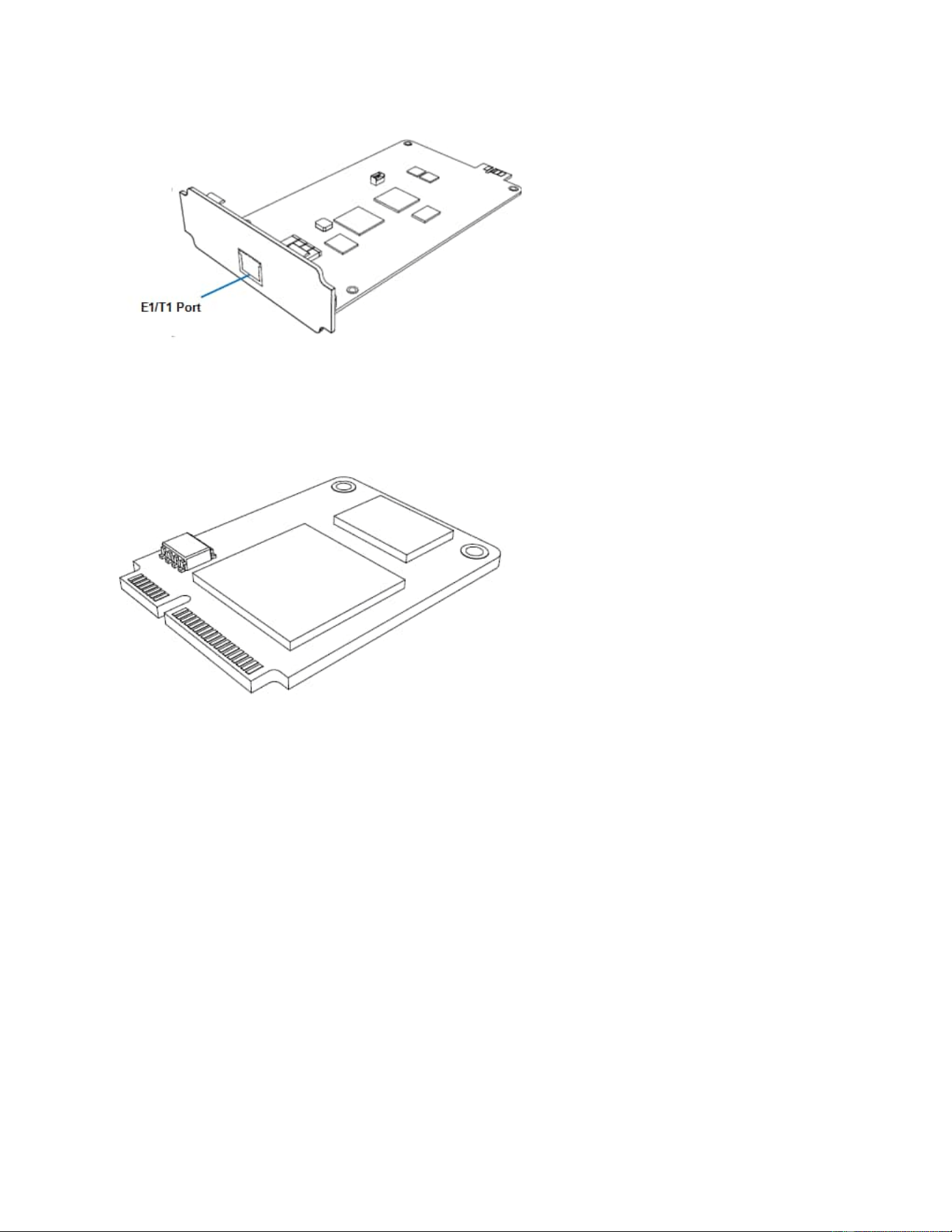
DS-KSME100 Module
DS-KSME100 is a DSP module, used to expand the capacity of SIP SERVER. With a DS-KSME100
module added, the extensions increase 100 and concurrent calls increase 30 additionally.
Install SIP SERVER
Installation Warnings
To avoid unexpected accident, personal injury or device damage, read the safety disclaimers
and installation warnings.
Power Safety
• Use only the power cord or power adapter provided with the SIP SERVER.
• Keep the power off during the installation.
• Make sure that the supply voltage matches the specifications indicated on the back
panel of the device.
• To avoid the electric accident, do not open or remove the cover of SIP SERVER
when it is working as well as off the power.

• Before cleaning the device, cut off the power supply.
Environment
Install the PBX in a location that is clean, free from vibration, electric shock, and tempera
ture/humidity extremes.
The operating temperature should be kept below 104°F (40°C).
Package Contents
Before you begin to install the SIP SERVER, check the package contents. If there is any
problem, contact your provider.
Install DS-KS6160/DS-KS6170
Install Telephony Module
Table .
60
70
DS-KSMET08
Expansion Board
Max. 1 Max. 2
DS-KSMETE1
Expansion Board
Max. 1 Max. 2
Telephony Module Max. 4 Max. 8
DS-KSME100 Max. 1 Max. 2
The optional telephony modules are as below:
• DS-KSMXO2 • DS-KSMXB2 • DS-KSM4G
• DS-KSMXS2
• DS-KSMXOS2 • DS-KSMGSM
Note:
Before installing the module, check if the module is clean and intact.
1. Loosen the screws at the bottom of the device and remove the upper cover.
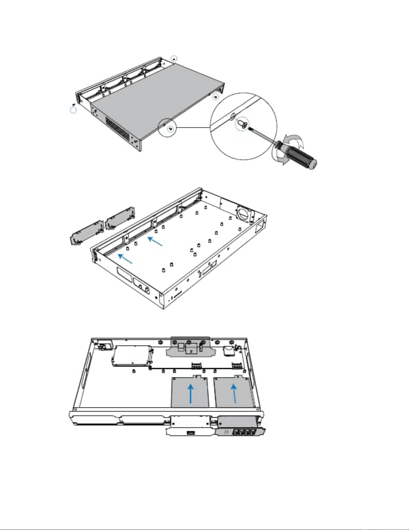
2. Push out the empty board from the inside of the device.
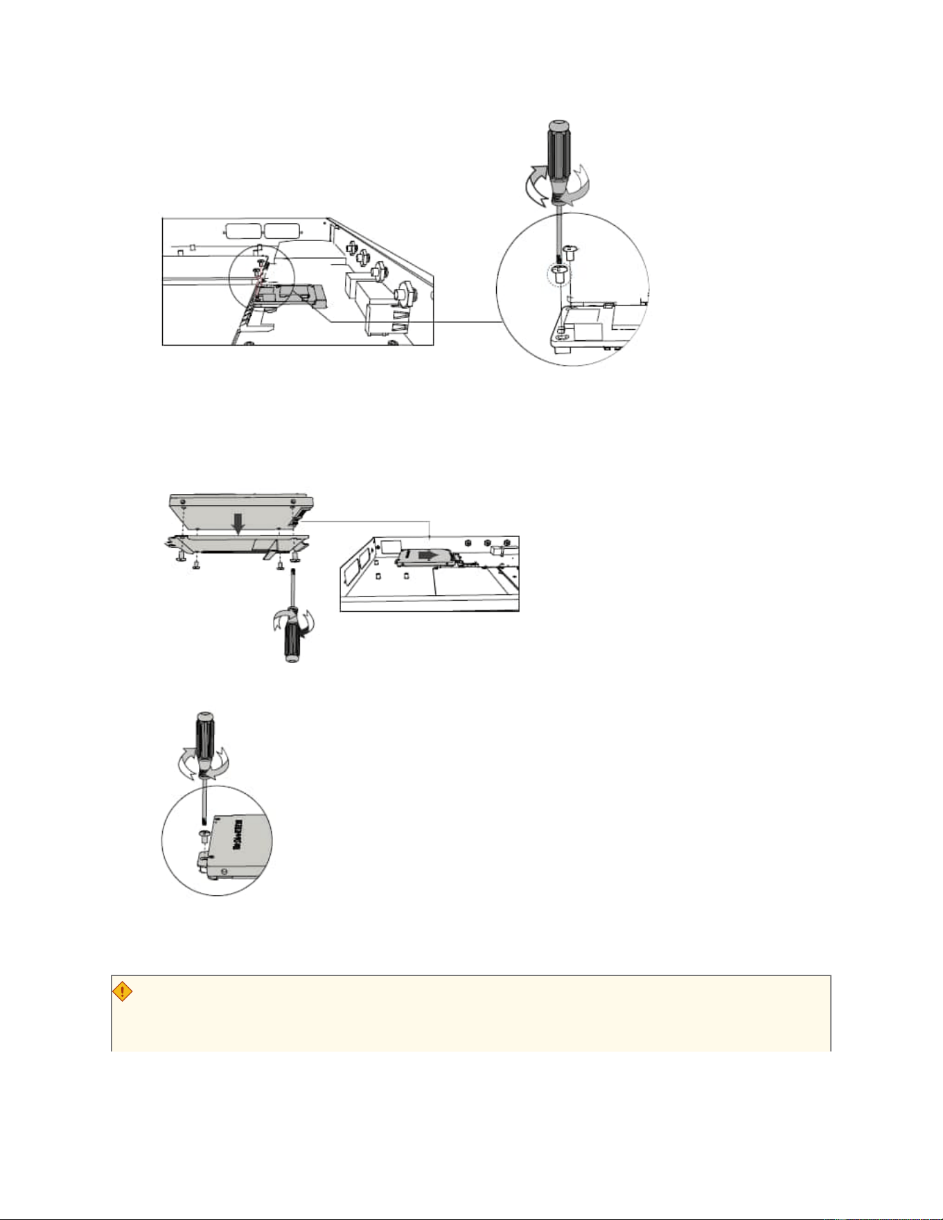
3. Push in the Expansion Board (DS-KSMETE1 or DS-KSMET08).
4. Lock the screws to fix the Expansion Board.
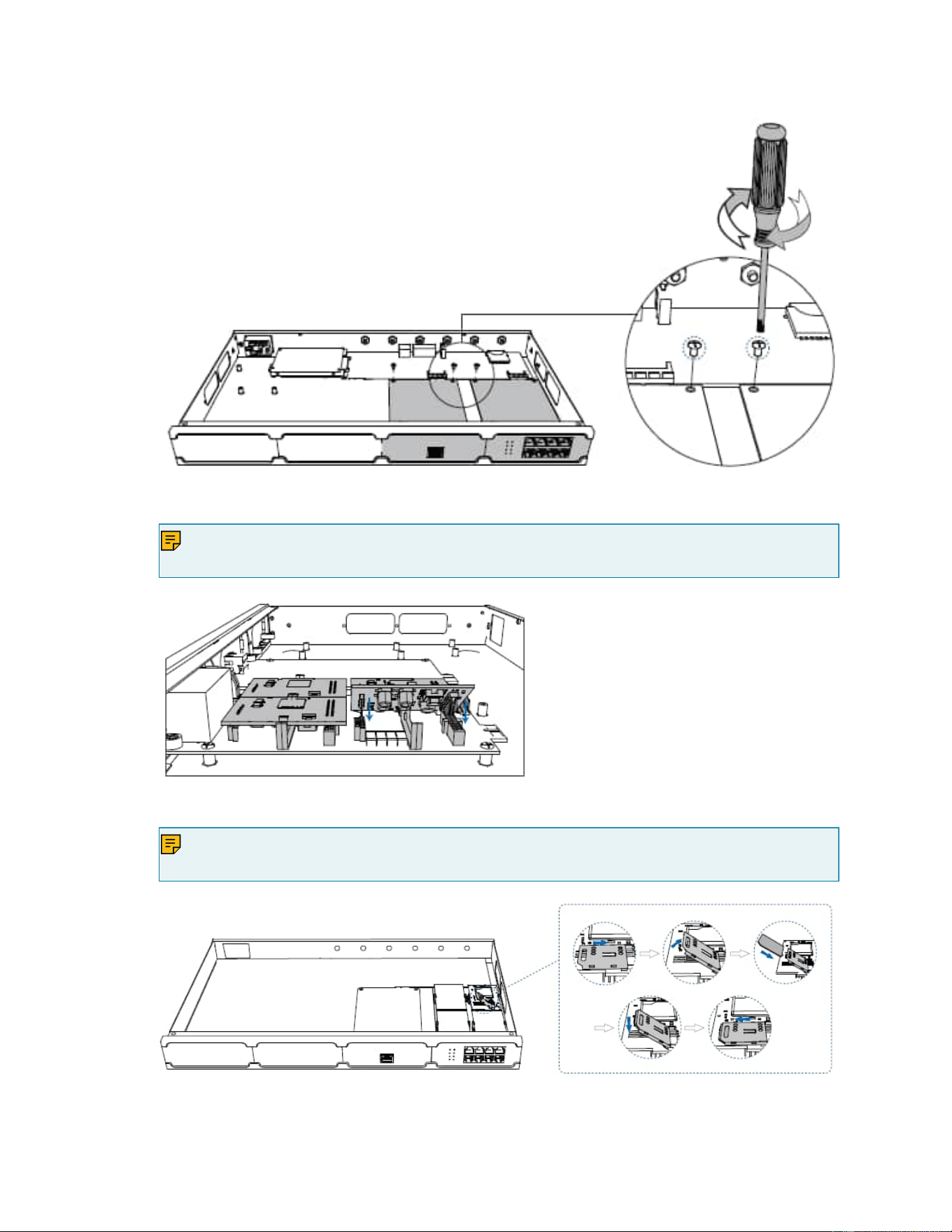
5. Insert the Telephony Modules on the DS-KSMET08 Board.
Note:
Skip this step for DS-KSMETE1Board.
6. Follow the instructions to insert a SIM card on the DS-KSM4G/DS-KSMGSM module.
Note:
Skip this step if no GSM/3G/4G module is installed.
7. Close the cover and fix the screws.
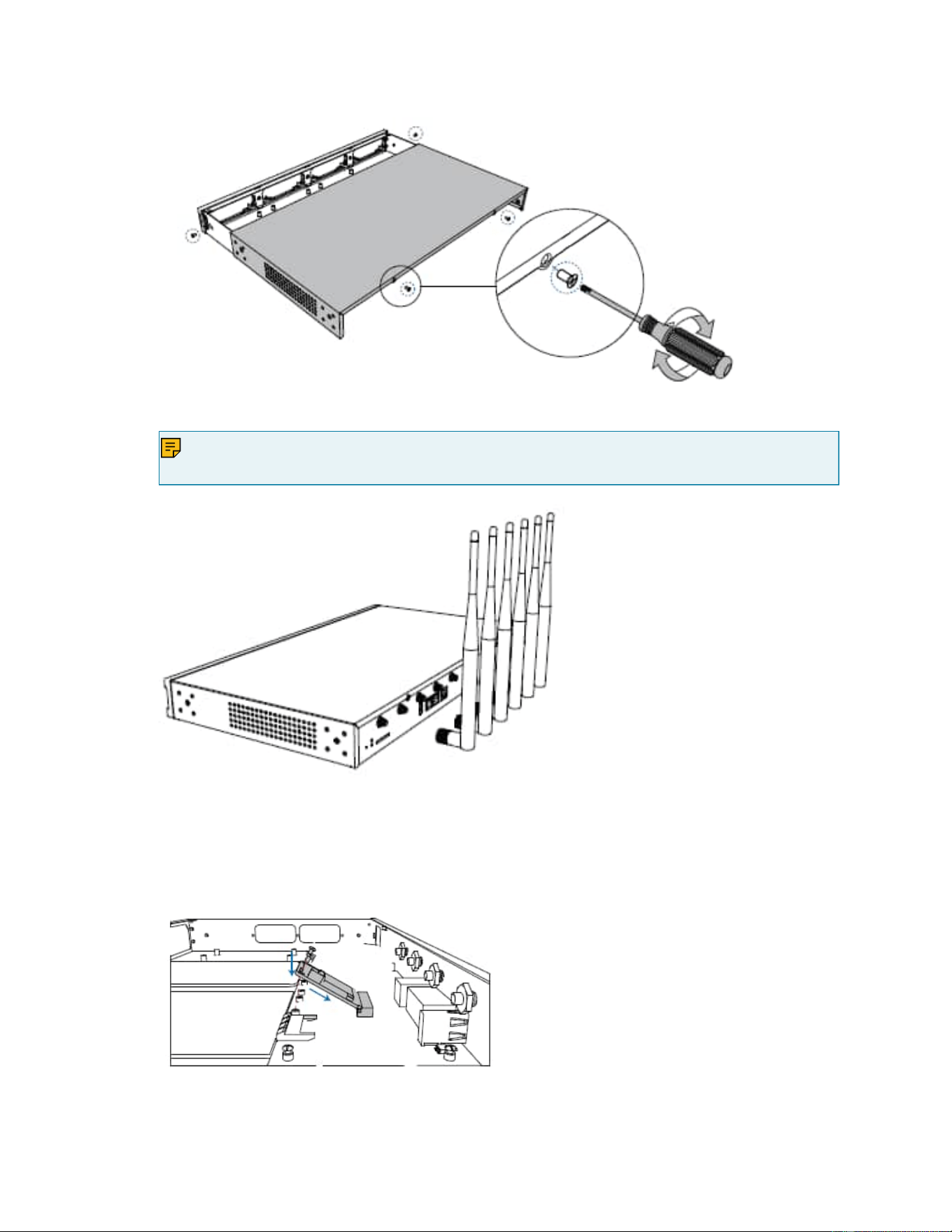
8. Rotate the antenna into the Antenna Socket.
Note:
Skip this step if no GSM/3G/4G module installed.
Install DSP Module
1. Open the device upper cover and insert the DSP module (DS-KSME100) into the D-Slot from a
tilt angle and then press it down.
2. Lock the screws to fix the DS-KSME100 module board.
Hard Disk Installation
1. Lock the hard disk on the bracket and push the hard disk into the bracket.
2. Lock the screw to fix the hard disk.
Desktop Installation
CAUTION:
• Set 5~10cm gaps around the device for air circulation.
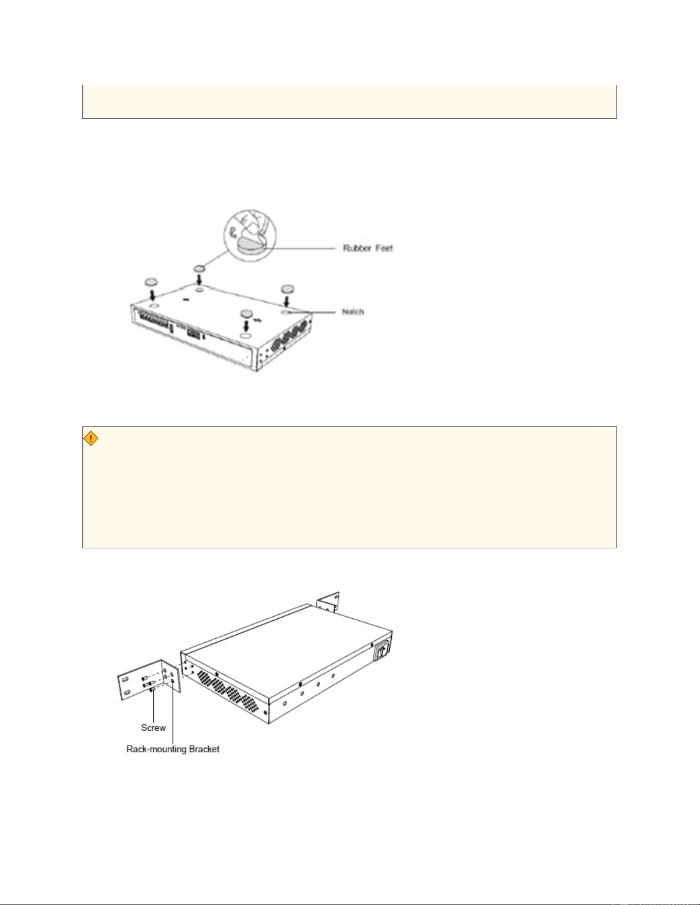
• Avoid any heavy thing placed on the device.
1. Place the SIP SERVER on a steady platform.
2. Remove the adhesive backing paper from the rubber feet.
3. Turn over the device and attach the supplied rubber feet to the recessed areas on the
bottom at each corner of the device.
Rack Installation
CAUTION:
• Be careful not to drop any components. Dropping components may damage them or
cause an injury.
• Only use the 19-inch rack mounting kits (attached bracket and fittings) included with
the SIP SERVER.
1. Fix the brackets to the left and right sides of the SIP SERVER with 4 screws
2. Place the SIP SERVER in the 19-inch rack and fix both brackets to the rack with the rack’s pro
prietary mounting equipment.
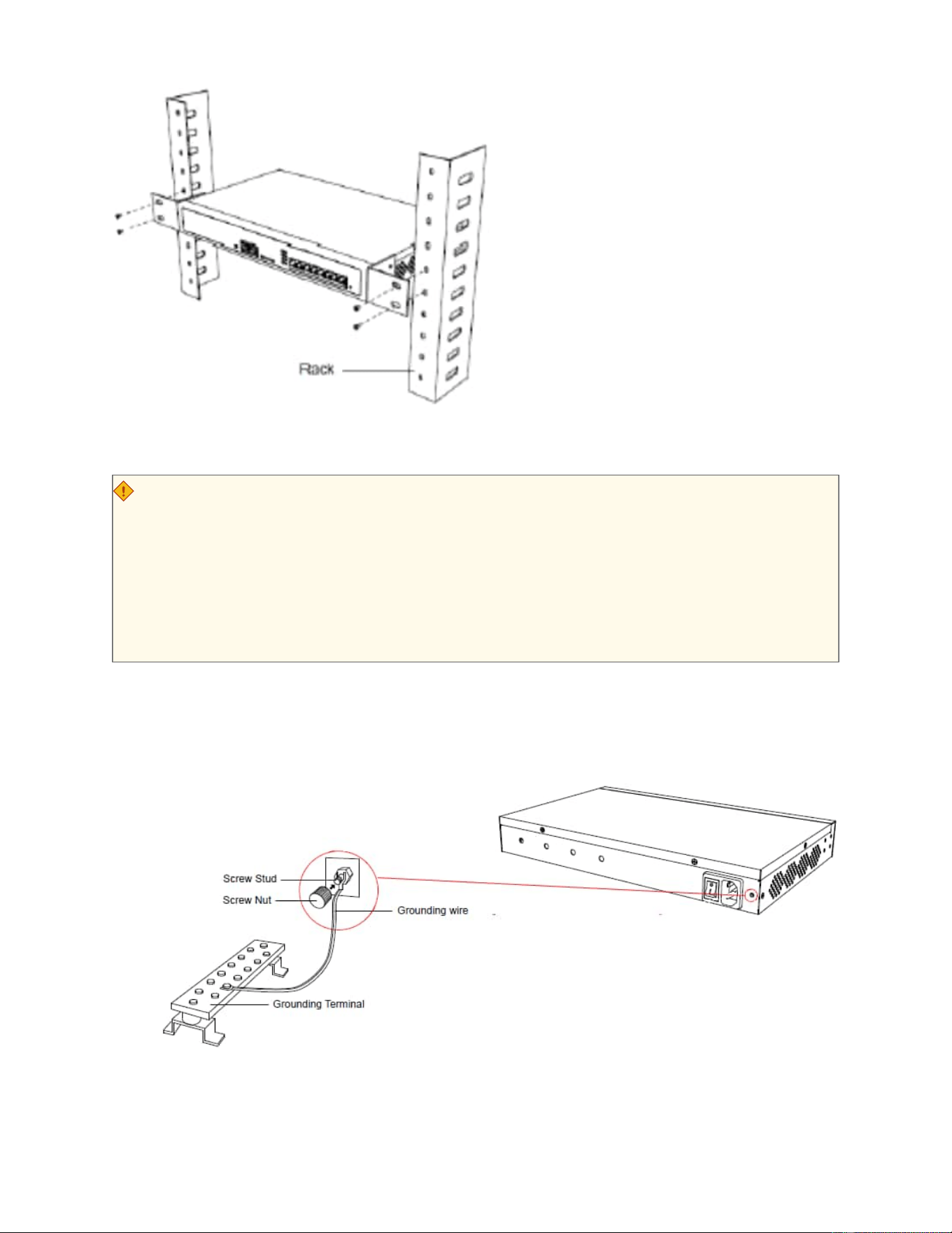
Ground Connection
CAUTION:
• Proper grounding (connection to ground) is very important to reduce the risk of elec
trocution to the user or protect the SIP SERVER from the bad effects of external noise
in the case of a lightning strike.
• A permanent connection between ground and the ground terminal of the SIP SERVER
must be made.
1. Tighten the provided screw stud into the Grounding port on SIP SERVER.
2. Insert an 18AWG grounding wire (user supplied).
3. Tighten the provided screw nut.
4. Attach the grounding wire to the grounding terminal.

Getting Started
Log in to SIP SERVER Web Portal
SIP SERVER System provides two different web portals for users with different roles to
quickly access, set up, and manage the system. This topic describes the difference
between them, and introduces how to log in to the SIP SERVER web portal.
Web portals overview
Table 1.
Web portal Description
Administrator portal Dedicated web portal for super administrator.
Super administrator has the highest privileges. Once logged in, the
super administrator can access and manage all the SIP SERVER
system features, including creating extension accounts for users and
granting privileges to the created user accounts.
Login address: IP address/admin.
Management portal The web portal for users with administrative privileges.
Users who have a specific role assigned by the super administrator can log
in through this portal. Once logged in, users can only access and manage
the specific PBX system features that are granted to their roles.
Login address: IP address.
Log in to administrator portal
Prerequisites
• You have connected the network cable.
Select either of the following two methods to connect network cable.
◦ Use a network cable to connect the LAN port of the SIP SERVER to
the network adapter port of the PC.

◦ Use a network cable to connect the LAN port of the SIP
SERVER to a switch or a router, and also connect your PC to
the switch or router.
• An operation and maintenance terminal (a PC) is available. The PC must
meet the following requirements:
◦ Have a web browser installed. The following table shows the com
patible browsers.
Table 2.
Web Browser Version
Google Chrome (recommended) Chrome 87 or later
Microsoft Edge Edge 87 or later
Opera Opera 72 or later
◦ Support the resolution of 1366 x 768 or higher.
• You have set the IP address of your PC.
The IP address of the PC must be on the same network segment as that of
the SIP SERVER and cannot conflict with IP addresses of other devices.
Note:
◦ The default IP address of SIP SERVER System is
192.168.5.150, and the default gateway address is
192.168.5.1.
◦ If you fail to access the SIP SERVER web portal, contact
your network administrator to check if your PC can
communicate with the IP address 192.168.5.150.
Procedure
1. Open the web browser, enter the SIP SERVER IP address in the address bar, fol
lowed by a forward slash and the word "admin", i.e. SIP SERVER IP
address/admin, and press Enter.
For example, the default IP address is 192.168.5.150, then you should
enter 192.168.5.150/admin.
Note:
If it is your first time to access the system, you will be redirected
to the Installation Wizard.
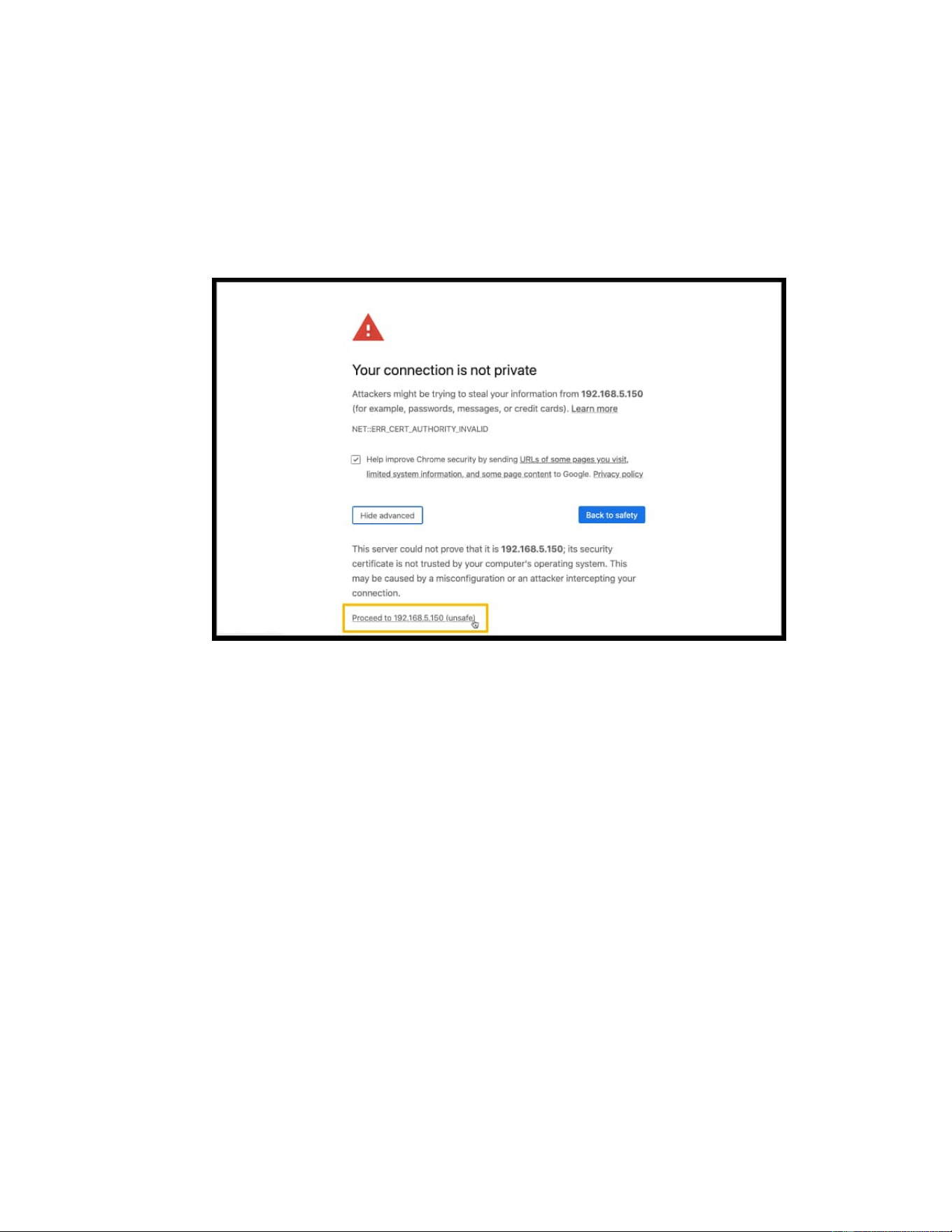
2. If a warning appears to remind you that the page is not secure, ignore
the warning on the web page, expand the Advanced tab, and proceed to
the SIP SERVER web.
3. Enter the credentials of the supper administrator account, then click
LOG IN.
• Username: The username or email address of super administra
tor account that you have configured in the Installation Wizard.
• Password: The password of the super administrator account.

4. If you have set up two-factor authentication, you need to enter an au
thentication code.
a. Enter the authentication code provided by an authenticator appli
cation or email.
b. Optional: Select the checkbox of Trusted Device
.
Note:
For the device from which you log in most frequently, you
can select the option to add it as a trusted device. In this
wa
y, you don't have to re-enter an authentication code
with this device for the next 180 days.
c. Click LOG IN.
Log in to management portal
Prerequisite
• An operation and maintenance terminal (a PC) is available. The PC must
meet the following requirements:
◦ Have a web browser installed. The following table shows the com
patible browsers.
Table 3.
Web Browser Version
Google Chrome (recommended) Chrome 87 or later
Web Browser Version
Microsoft Edge Edge 87 or later
Opera Opera 72 or later
◦ Support the resolution of 1366 x 768 or higher.
• You have set the IP address of your PC.
The IP address of the PC must be on the same network segment as that
of the PBX and cannot conflict with IP addresses of other devices.
Note:
◦ The default IP address of SIP SERVER System is
192.168.5.150, and the default gateway address is
192.168.5.1.
◦ If you fail to access the SIP SERVER web portal, contact
your network administrator to
check if your PC can
communicate with the IP address 192.168.5.150.
Procedure
1. Open the web browser, enter the IP address of the SIP SERVER in the
address bar, and press Enter
.
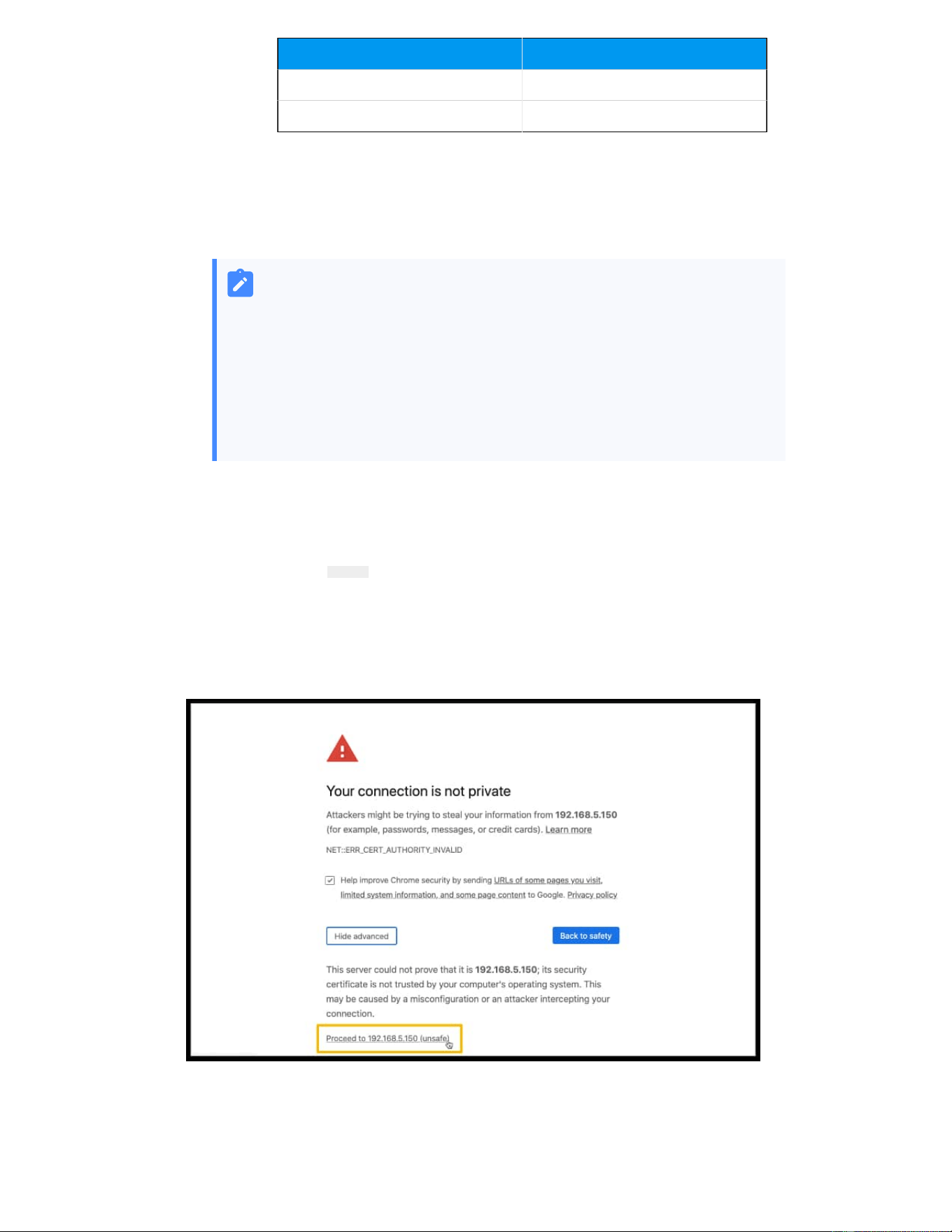
2. If a warning appears to remind you that the page is not secure, ignore
the warning on the web page, expand the Advanced tab, and proceed to
the SIP SERVER web.

3. Enter the credential of the user account, then click LOG I
N.
• Username: The email address or extension number of the user
account.
• Password: The password of the user account.
4. If you have set up two-factor authentication,, you need to enter an au
thentication code.
a. Enter the authentication code provided by an authenticator appli
cation or email.
b. Optional: Select the checkbox of Trusted Device.
Note:
For the device from which you log in most frequently, you
can select the option to add it as a trusted device. In this
way
, you don't have to re-enter an authentication code
with this device for the next 180 days.
c. Click LOG IN.
5. In the bottom left corner, click Access Management Portal.
Initial Setup Using the Installation Wizard
When you access the SIP SERVER web portal for the first time, you need to finish initial
configurations for the system using the Installation Wizard.
Prerequisites
You have accessed the SIP SERVER web portal and entered the Installation Wizard.
Warning:
The Installation Wizard only appears when you first configure the system with fac
tory settings.
Procedure
• Step 1. Configure the system network
• Step 2. Set up super administrator account
• Step 3. Configure the system time

• Step 4. Localize and customize the system
• Step 5. Check and confirm the configurations
Step 1. Configure the system network
Set the Ethernet mode and related configuration of corresponding Ethernet interface.
1. In the Basic section, select the Ethernet mode and default interface.
• Ethernet Mode: Select an Ethernet mode.
◦ Single: Only LAN interface is used for connection, WAN interface is dis
abled.
◦ Bridge: LAN interface is used for connection, WAN interface is used as
bridge for other devices' connection.
◦ Dual: Both LAN interface and WAN interface are used for connection.
Note:
Dual Ethernet mode is typically for the scenario that the Internet
Telephony Service Provider (ITSP) offers a dedicated networking
for VoIP communication.
• Default Interface: Optional. Select a default interface if the system is in dual
Ethernet mode.
2. In the LAN section, enter the network information for the LAN interface of the SIP
SERVER.
3. Optional: In the WAN section, enter the network information for the WAN interface of
the SIP SERVER.
4. Click Next.
A pop-up window appears and displays the information of network detection.
Step 2. Set up super administrator account
1. In the Basic section, enter the information of the super administrator account.
Note:
• Do NOT forget the username and password of the super administrator
account, or you need to reset your system to reconfigure the account
and log in to the PBX.

• The super administrator has access to all features on the system, and
the super administrator can assign administrator role to users.
• Username: Specify the username that is used to log in to SIP SERVER web portal.
• Password: Specify the password that is used to log in to SIP SERVER web portal.
• Repeat the password: Repeat the password to confirm.
• Email Address: Enter the email address of the super administrator.
The email address can be used to receive system notifications, reset web login
password, and log in to the administrator portal.
• Mobile Number: Enter the mobile number that can be used to receive system
notifications.
• Prefix: Optional. Enter the prefix according to the dial pattern of the outbound
route, so that the system
can successfully send calls to the mobile number.
2. In the Event Notifications section, configure event notifications for the super
administrator.
• Send Event Notification to SIP SERVER Administrator: Decide whether to
enable notifications for the super administrator or not.
• Contact Name: Enter the name of the super administrator.
Note:
This name helps you identify the super administrator from the Notifica
tion Contacts list.
• Notification Level: System notifications are divided into different levels ac
cording to importance. You can select notification levels to filter and receive the
relevant notifications.
• Notification Method: Select method(s) to receive notifications.
For more information of event notifications, see Event Notification Overview.
3. Click Next.
Step 3. Configure the system time
1. In the Date and Time section, configure the time zone and daylight saving time, and
set up the date and time manually or synchronize with an NTP server.

Note:
To synchronize system time with an NTP server, make sure that the PBX can
access the Internet.
2. In the Display Format section, select the display format for date and time.
3. Click Next.
Step 4. Localize and customize the system
1. In the System Prompt Language section, select the radio button beside a system
prompt to set it as the default system prompt.
Note:
Click Download Online Prompts to download more prompts.
2. In the Other Settingssection, adjust the following settings for your local installation.
• Notification Email Language: Select which language of email contents to be
received.
• Device Name: Specify a name for the SIP SERVER system.
• Name Display Format: Select the display format for Extension User's Name
and Contact Name.
• Tone Region: Select your country/region or the nearest neighboring country/re
gion to enable the default dial tone, busy tone, ring tone for your region.
• Enable Allowed Country/Region Code Dialing Protection: To restrict users
from making international calls, enable this option. When enabled, users can not
make international calls to any countries or regions.
Note:
To allow users to make international calls to specific countries or re
gions, you need to grant permission to desired users, and set the al
lowed countries or regions. For more information, see Restrict Interna
tional Calls to Specific Countries or Regions.
• International Dialing Code: Enter the prefix of international call according to
your country.
When a user tries to call a number starting with the prefix, the SIP SERVER
outbound route will identify this call as an international call.
3. Click Next to see the summary.

Step 5. Check and confirm the configurations
1. Check the all the configured settings on the Summary page.
2. To edit the configurations of a specific step, click beside the step title.
3. To edit the configurations of the previous step, click Re-configure.
4. If all the configurations are confirmed, click Reboot to take effect.
Result
All the configurations take effect after the system reboots.
You need to access the new IP address of the SIP SERVER and log in to SIP SERVER web
portal by the super administrator username and password.
Note:
The IP address of your PC must be on the same network segment as that of
the SIP SERVER, or you cannot access the SIP SERVER.
Change the Password of Super Administrator
If you know the current password of super administrator, you can log in to the SIP SERVER
administrator portal and follow the steps to change the super administrator's password.
Background information
The username and password of super administrator are configured in Installation Wizard.
Important:
• The username of super administrator cannot be changed unless your reset
the system.
• If you forget the password of super administrator, you can reset the pass
word. For more information, see Reset the Password of Super Administrator.
Procedure
1. Log in to SIP SERVER administrator portal.

2. At the top-right corner of the web page, click and select Change Password.
3. On the pop-up window, enter the old password and new password.
4. Click Save.
Result
The password is reset, you will be logged out of the web page automatically. To log in to
SIP SERVER administrator portal, enter the new password.
Reset the Password of Super Administrator
As a super administrator, you can reset your web login password if you forget the password.
Prerequisites
• If your device is deployed on the local LAN and cannot access the network, you can
only change the password on the device and cannot use the mailbox
Important:
If you forget the username of super administrator, you need to reset the sys
tem to reconfigure a new username.
• For Basic Plan, you can only reset your password in the local network of the SIP
SERVER system.
Procedure
1. Access the SIP SERVER web login page, click Forgot Password? to enter the Forget Pass-
word page.
2. On the Forget Password page, enter the following information:
• Extension number or username: The username of super administrator.
• Email Address
: The email address that is associated with the super adminis
trator.
3. Click Send.
A password reset email is sent to super administrator
's email address.
4. Check the password reset email, and click the link provided in the email to enter the
Reset Password page.

This link is valid for 30 minutes and can only be used once.
5. On the Reset Password page, enter your new password twice, and click Save.
Result
The password of super administrator is changed. You need to log in to SIP SERVER
administrator portal by the new password next time.
Set up Company Information
Company information contains basic information about your company, including company
name, company phone number, and company address. This topic describes how to set up
company information.
Procedure
1. Log in to SIP SERVER web portal.
2. At the top-right corner of the web page, click and select Company
Information.
3. In the pop-up window, do as follows:
a. Configure the name, the phone number, and the address of your company as
needed.

Note:
If you enable Organization Management feature on the system, the
Company Name is required and will be used as the root organization
name. For more information, see Enable or Disable Organization Man
agement.
b. Click Save.
View System Information
This topic describes how to view a summary of information about your system hardware,
firmware and network.
Procedure
1. Log in to SIP SERVER web portal, go to Dashboard.
2. At the top-right corner of Dashboard, click Information.
The following information is displayed:
• Network
• Device Name
• Product Model
• Serial Number
• Hardware Version
• Firmware Version
• System Time
• Uptime
• Maximum Extensions
• Maximum Concurrent Calls
