
Legal Informaon
About this Document
●
This Document includes instrucons for using and managing the Product. Pictures, charts,
images and all other
informaon hereinaer are for descripon and explanaon only.
●
The
informaon contained in the Document is subject to change, without noce, due to
rmware updates or other reasons. Please nd the latest version of the Document at the
Hikvision website ( hps://www.hikvision.com ). Unless otherwise agreed, Hangzhou Hikvision
Digital Technology Co., Ltd. or its aliates (hereinaer referred to as "Hikvision") makes no
warranes, express or implied.
●
Please use the Document with the guidance and assistance of professionals trained in
supporng the Product.
About this Product
●
This product can only enjoy the aer-sales service support in the country or region where the
purchase is made.
●
If the product you choose is a video product, please scan the following QR code to obtain the
"Iniaves on the Use of Video Products", and read it carefully.
Acknowledgment of Intellectual Property Rights
●
Hikvision owns the copyrights and/or patents related to the technology embodied in the
Products described in this Document, which may include licenses obtained from third pares.
●
Any part of the Document, including text, pictures, graphics, etc., belongs to Hikvision. No part
of this Document may be excerpted, copied, translated, or modied in whole or in part by any
means without
wrien permission.
●
and other Hikvision’s trademarks and logos are the properes of Hikvision in
various
jurisdicons.
●
Other trademarks and logos menoned are the properes of their respecve owners.
LEGAL DISCLAIMER
●
TO THE MAXIMUM EXTENT PERMITTED BY APPLICABLE LAW, THIS DOCUMENT AND THE
PRODUCT DESCRIBED, WITH ITS HARDWARE, SOFTWARE AND FIRMWARE, ARE PROVIDED "AS
IS" AND "WITH ALL FAULTS AND ERRORS". HIKVISION MAKES NO WARRANTIES, EXPRESS OR
Smart Monitoring Camera User Manual
i

IMPLIED, INCLUDING WITHOUT LIMITATION, MERCHANTABILITY, SATISFACTORY QUALITY, OR
FITNESS FOR A PARTICULAR PURPOSE. THE USE OF THE PRODUCT BY YOU IS AT YOUR OWN RISK.
IN NO EVENT WILL HIKVISION BE LIABLE TO YOU FOR ANY SPECIAL, CONSEQUENTIAL,
INCIDENTAL, OR INDIRECT DAMAGES, INCLUDING, AMONG OTHERS, DAMAGES FOR LOSS OF
BUSINESS PROFITS, BUSINESS INTERRUPTION, OR LOSS OF DATA, CORRUPTION OF SYSTEMS, OR
LOSS OF DOCUMENTATION, WHETHER BASED ON BREACH OF CONTRACT, TORT (INCLUDING
NEGLIGENCE), PRODUCT LIABILITY, OR OTHERWISE, IN CONNECTION WITH THE USE OF THE
PRODUCT, EVEN IF HIKVISION HAS BEEN ADVISED OF THE POSSIBILITY OF SUCH DAMAGES OR
LOSS.
●
YOU ACKNOWLEDGE THAT THE NATURE OF THE INTERNET PROVIDES FOR INHERENT SECURITY
RISKS, AND HIKVISION SHALL NOT TAKE ANY RESPONSIBILITIES FOR ABNORMAL OPERATION,
PRIVACY LEAKAGE OR OTHER DAMAGES RESULTING FROM CYBER-ATTACK, HACKER ATTACK,
VIRUS INFECTION, OR OTHER INTERNET SECURITY RISKS; HOWEVER, HIKVISION WILL PROVIDE
TIMELY TECHNICAL SUPPORT IF REQUIRED.
●
YOU AGREE TO USE THIS PRODUCT IN COMPLIANCE WITH ALL APPLICABLE LAWS, AND YOU ARE
SOLELY RESPONSIBLE FOR ENSURING THAT YOUR USE CONFORMS TO THE APPLICABLE LAW.
ESPECIALLY, YOU ARE RESPONSIBLE, FOR USING THIS PRODUCT IN A MANNER THAT DOES NOT
INFRINGE ON THE RIGHTS OF THIRD PARTIES, INCLUDING WITHOUT LIMITATION, RIGHTS OF
PUBLICITY, INTELLECTUAL PROPERTY RIGHTS, OR DATA PROTECTION AND OTHER PRIVACY
RIGHTS. YOU SHALL NOT USE THIS PRODUCT FOR ANY PROHIBITED END-USES, INCLUDING THE
DEVELOPMENT OR PRODUCTION OF WEAPONS OF MASS DESTRUCTION, THE DEVELOPMENT OR
PRODUCTION OF CHEMICAL OR BIOLOGICAL WEAPONS, ANY ACTIVITIES IN THE CONTEXT
RELATED TO ANY NUCLEAR EXPLOSIVE OR UNSAFE NUCLEAR FUEL-CYCLE, OR IN SUPPORT OF
HUMAN RIGHTS ABUSES.
●
IN THE EVENT OF ANY CONFLICTS BETWEEN THIS DOCUMENT AND THE APPLICABLE LAW, THE
LATTER PREVAILS.
© Hangzhou Hikvision Digital Technology Co., Ltd. All rights reserved.
Smart Monitoring Camera User Manual
ii
Symbol Convenons
The symbols that may be found in this document are dened as follows.
Symbol Descripon
Danger
Indicates a hazardous situaon which, if not avoided, will or could
result in death or serious injury.
Cauon
Indicates a potenally hazardous situaon which, if not avoided, could
result in equipment damage, data loss, performance degradaon, or
unexpected results.
Note
Provides addional informaon to emphasize or supplement
important points of the main text.
Smart Monitoring Camera User Manual
iii

Contents
Chapter 1 Acvaon and Login ................................................................................................... 1
1.1 Acvaon ............................................................................................................................... 1
1.1.1 Default Informaon ...................................................................................................... 1
1.1.2 Acvate via SADP .......................................................................................................... 1
1.1.3 Acvate via Web Browser ............................................................................................. 2
1.2 Login ...................................................................................................................................... 3
Chapter 2 Applicaon Mode Conguraon ................................................................................. 4
2.1 Set Smart Monitoring Capture ............................................................................................... 4
2.2 Set Incident
Detecon ........................................................................................................... 7
2.2.1 Set Violaon and Incident Detecon ............................................................................ 8
2.2.2 Set Linked Lane Parameters ........................................................................................ 10
2.2.3 Draw Lane Lines and
Detecon Areas ......................................................................... 11
2.2.4 Set Data Collecon ...................................................................................................... 13
2.3 Set License Plate Recognion System Capture .................................................................... 16
Chapter 3 Capture Parameters
Conguraon ............................................................................ 20
3.1 Set License Plate Recognion Parameters ........................................................................... 20
3.2 Set Supplement Light Parameters ........................................................................................ 20
3.3 Set Vehicle Feature Parameters ........................................................................................... 21
3.4 Set Body Picture
Mang ..................................................................................................... 22
3.5 Set Picture Composion ...................................................................................................... 22
3.6 Set
Informaon Overlay ....................................................................................................... 23
3.6.1 Set Single Picture Overlay ........................................................................................... 23
3.6.2 Set Composite Picture Overlay .................................................................................... 25
3.7 Set Image Encoding Parameters .......................................................................................... 27
3.8 Set Capture Schedule ........................................................................................................... 28
3.9 Set Captured Image Parameters .......................................................................................... 29
Smart Monitoring Camera User Manual
iv

3.10 Set ICR ................................................................................................................................ 30
3.11 Debug ................................................................................................................................. 31
3.11.1 Debug Device ............................................................................................................ 31
3.11.2 Vehicle Capture and
Recognion Service .................................................................. 32
3.11.3 Set Image Format ...................................................................................................... 33
3.12 Set Barrier Gate Linkage ..................................................................................................... 34
3.12.1 Set Allowlist and Blocklist ......................................................................................... 34
3.12.2 Control Barrier Gate .................................................................................................. 35
3.12.3 Set Wiegand Parameters ........................................................................................... 37
Chapter 4 View Real-Time Picture ............................................................................................. 39
Chapter 5 View Trac Stascs ................................................................................................ 41
5.1 View Real-Time Trac Stascs .......................................................................................... 41
5.2 View
Trac Flow Stascs ................................................................................................... 41
Chapter 6 Live View and Local
Conguraon ............................................................................ 42
6.1 Live View .............................................................................................................................. 42
6.1.1 Start/Stop Live View .................................................................................................... 42
6.1.2 Select Image Display Mode ......................................................................................... 42
6.1.3 Select Window Division Mode .................................................................................... 42
6.1.4 Select Stream Type ...................................................................................................... 42
6.1.5 Capture Picture Manually ........................................................................................... 42
6.1.6 Record Manually ......................................................................................................... 42
6.1.7 Start/Stop Two-Way Audio .......................................................................................... 43
6.1.8 Enable/Disable Audio .................................................................................................. 43
6.1.9 Enable Digital Zoom .................................................................................................... 43
6.1.10 Enable Regional Focus .............................................................................................. 44
6.1.11 Select Video Mode .................................................................................................... 44
6.2 PTZ
Operaon ...................................................................................................................... 44
6.3 Local
Conguraon .............................................................................................................. 46
Smart Monitoring Camera User Manual
v

Chapter 7 Record and Capture .................................................................................................. 50
7.1 Set Storage Path ................................................................................................................... 50
7.1.1 Set Storage Card .......................................................................................................... 50
7.1.2 Set Quota .................................................................................................................... 51
7.1.3 Set FTP ........................................................................................................................ 51
7.1.4 Set Cloud Storage ........................................................................................................ 53
7.2 Set Record Schedule ............................................................................................................ 54
7.3 Set Snapshot Schedule ......................................................................................................... 56
7.4 Search Picture ...................................................................................................................... 56
7.5 Playback ............................................................................................................................... 57
Chapter 8 Encoding and Display ................................................................................................ 59
8.1 Set Video Encoding Parameters ........................................................................................... 59
8.2 Set Image Parameters .......................................................................................................... 60
8.3 Set ROI ................................................................................................................................. 63
8.4 Set Privacy Mask .................................................................................................................. 64
8.5 Enable Regional Exposure .................................................................................................... 65
8.6 Set OSD ................................................................................................................................ 66
Chapter 9 Network Conguraon ............................................................................................. 68
9.1 Set IP Address ...................................................................................................................... 68
9.2 Set Port ................................................................................................................................ 71
9.3 Set IEEE 802.1X .................................................................................................................... 72
9.4 Set DDNS .............................................................................................................................. 73
9.5 Set SNMP ............................................................................................................................. 73
9.6 Set QoS ................................................................................................................................. 75
9.7 Connect to
Plaorm ............................................................................................................. 75
9.7.1 Set Arm Host ............................................................................................................... 75
9.7.2 Set SDK Listening ......................................................................................................... 76
9.7.3 Set ISAPI Listening ....................................................................................................... 77
Smart Monitoring Camera User Manual
vi

9.7.4 Connect to ISUP Plaorm ........................................................................................... 79
9.7.5 Connect to OTAP ......................................................................................................... 80
9.7.6 Connect to Hik-Connect .............................................................................................. 82
9.8 Set
Integraon Protocol ....................................................................................................... 84
Chapter 10 Serial Port Conguraon ......................................................................................... 85
10.1 Set RS-485 .......................................................................................................................... 85
10.2 Set RS-232 .......................................................................................................................... 86
Chapter 11 Event and Alarm ..................................................................................................... 87
11.1 Excepon Alarm ................................................................................................................. 87
11.2 Set Email ............................................................................................................................ 87
11.3 Set Email Event .................................................................................................................. 88
Chapter 12 Safety Management ............................................................................................... 90
12.1 Manage User ...................................................................................................................... 90
12.2 Enable User Lock ................................................................................................................ 90
12.3 Set SSH ............................................................................................................................... 91
12.4 Prohibit PING ..................................................................................................................... 91
12.5 Enable System Log Service ................................................................................................. 91
12.6 Set Timeout Logout ............................................................................................................ 92
12.7 Set Password Validity Period .............................................................................................. 92
12.8 Set SDK Protocol
Authencaon Mode ............................................................................. 92
12.9 Set RTSP Authencaon .................................................................................................... 93
12.10 Set IP Address Filtering .................................................................................................... 93
12.11 Set HTTPS ......................................................................................................................... 93
12.11.1 Create and Install Self-signed
Cercate ................................................................ 93
12.11.2 Install Authorized Cercate ................................................................................... 94
Chapter 13 Maintenance .......................................................................................................... 95
13.1 View Device
Informaon .................................................................................................... 95
13.2 Synchronize Time ............................................................................................................... 95
Smart Monitoring Camera User Manual
vii

13.3 Set DST ............................................................................................................................... 96
13.4 Reboot ............................................................................................................................... 96
13.5 Restore Parameters ............................................................................................................ 97
13.6 Export Parameters ............................................................................................................. 97
13.7 Export Debug File ............................................................................................................... 97
13.8 Export Diagnosis
Informaon ............................................................................................ 98
13.9 Upgrade ............................................................................................................................. 98
13.10 Import Conguraon File ................................................................................................. 98
13.11 Log ................................................................................................................................... 99
13.11.1 Enable Log According to Module ............................................................................ 99
13.11.2 Search Log ............................................................................................................... 99
13.12 Enable Maintenance Service .......................................................................................... 100
Smart Monitoring Camera User Manual
viii

Chapter 1 Acvaon and Login
1.1 Acvaon
For the rst-me access, you need to acvate the device by seng an admin password. No
operaon is allowed before acvaon. The device supports mulple acvaon methods, such as
acvaon via SADP soware, web browser, and iVMS-4200 Client.
Note
Refer to the user manual of iVMS-4200 Client for the acvaon via client soware.
1.1.1 Default Informaon
The device default informaon is shown as below.
●
Default IP address: 192.168.1.64
●
Default user name: admin
1.1.2
Acvate via SADP
SADP is a tool to detect, acvate, and modify the IP address of the device over the LAN.
Before You Start
●
Get the SADP soware from the supplied disk or the ocial website ( hp://
www.hikvision.com/ ), and install it according to the prompts.
●
The device and the computer that runs the SADP tool should belong to the same network
segment.
The following steps show how to
acvate one device and modify its IP address. For batch acvaon
and IP address modicaon, refer to User Manual of SADP for details.
Steps
1.
Run the SADP soware and search the online devices.
2.
Find and select your device in online device list.
3.
Enter a new password (admin password) and
conrm the password.
Cauon
STRONG PASSWORD RECOMMENDED-We highly recommend you create a strong password of
your own choosing (using a minimum of 8 characters, including upper case leers, lower case
leers, numbers, and special characters) in order to increase the security of your product. And
we recommend you reset your password regularly, especially in the high security system,
reseng the password monthly or weekly can beer protect your product.
4.
Click Acvate to start acvaon.
Smart Monitoring Camera User Manual
1
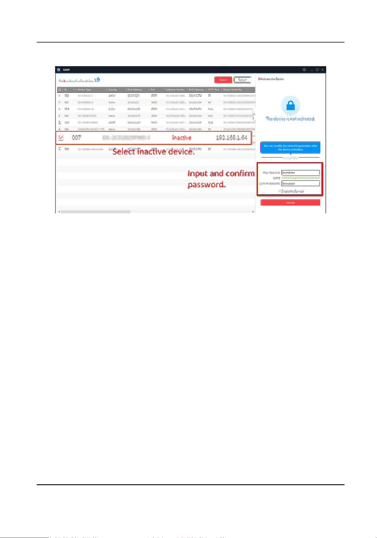
Figure 1-1 Acvate via SADP
Status of the device becomes Acve aer successful acvaon.
5.
Modify IP address of the device.
1) Select the device.
2) Change the device IP address to the same network segment as your computer by either
modifying the IP address manually or checking Enable DHCP (Dynamic Host
Conguraon
Protocol).
3) Enter the admin password and click Modify to
acvate your IP address modicaon.
1.1.3
Acvate via Web Browser
Use web browser to acvate the device. For the device with the DHCP enabled by default, use
SADP soware or client soware to acvate the device.
Before You Start
Ensure the device and the computer are in the LAN with the same network segment.
Steps
1.
Change the IP address of your computer to the same network segment as the device.
2.
Open the web browser, and enter the default IP address of the device to enter the
acvaon
interface.
3.
Create and conrm the admin password.
Smart Monitoring Camera User Manual
2

Cauon
STRONG PASSWORD RECOMMENDED-We highly recommend you create a strong password of
your own choosing (using a minimum of 8 characters, including upper case leers, lower case
leers, numbers, and special characters) in order to increase the security of your product. And
we recommend you reset your password regularly, especially in the high security system,
reseng the password monthly or weekly can beer protect your product.
4.
Click OK to complete acvaon.
5.
Go to the network sengs interface to modify IP address of the device.
1.2 Login
You can log in to the device via web browser for further operaons such as live view and local
conguraon.
Before You Start
Connect the device to the network directly, or via a switch or a router.
Steps
1.
Open the web browser, and enter the IP address of the device to enter the login interface.
2.
Enter User Name and Password.
3.
Click Login.
4.
Download and install appropriate plug-in for your web browser. Follow the
installaon prompts
to install the plug-in.
5.
Reopen the web browser
aer the installaon of the plug-in and repeat steps 1 to 3 to login.
6.
Oponal: Click Logout on the upper right corner of the interface to log out of the device.
Smart Monitoring Camera User Manual
3
Chapter 2 Applicaon Mode Conguraon
Note
●
The supported applicaon modes vary with dierent models. The actual device prevails.
●
When you draw lane lines or detecon areas on Applicaon Mode interface:
○
You can enable Display All Areas to display all the lines and areas, convenient to view the
eect of all the lines and areas. If you uncheck it, only the current selected lane will be
displayed, convenient to draw the current lane.
○
You can enable Small Target
Detecon and draw the small target detecon areas which are
always set at the road distance to raise the detecon eect of the distant targets.
○
The system will capture a picture and use it as the background. You can also enable Video
Background to use the live view as the background.
Cauon
You can click Default on Applicaon Mode interface to restore all the set parameters to the default
sengs. Please operate with care.
2.1 Set Smart Monitoring Capture
The smart monitoring mode supports capturing motor vehicles, non-motor vehicles, and
pedestrians via video triggering.
Steps
1.
Go to
Conguraon → Capture → Applicaon Mode .
2.
Select Applicaon Mode as Smart Mode.
Smart Monitoring Camera User Manual
4
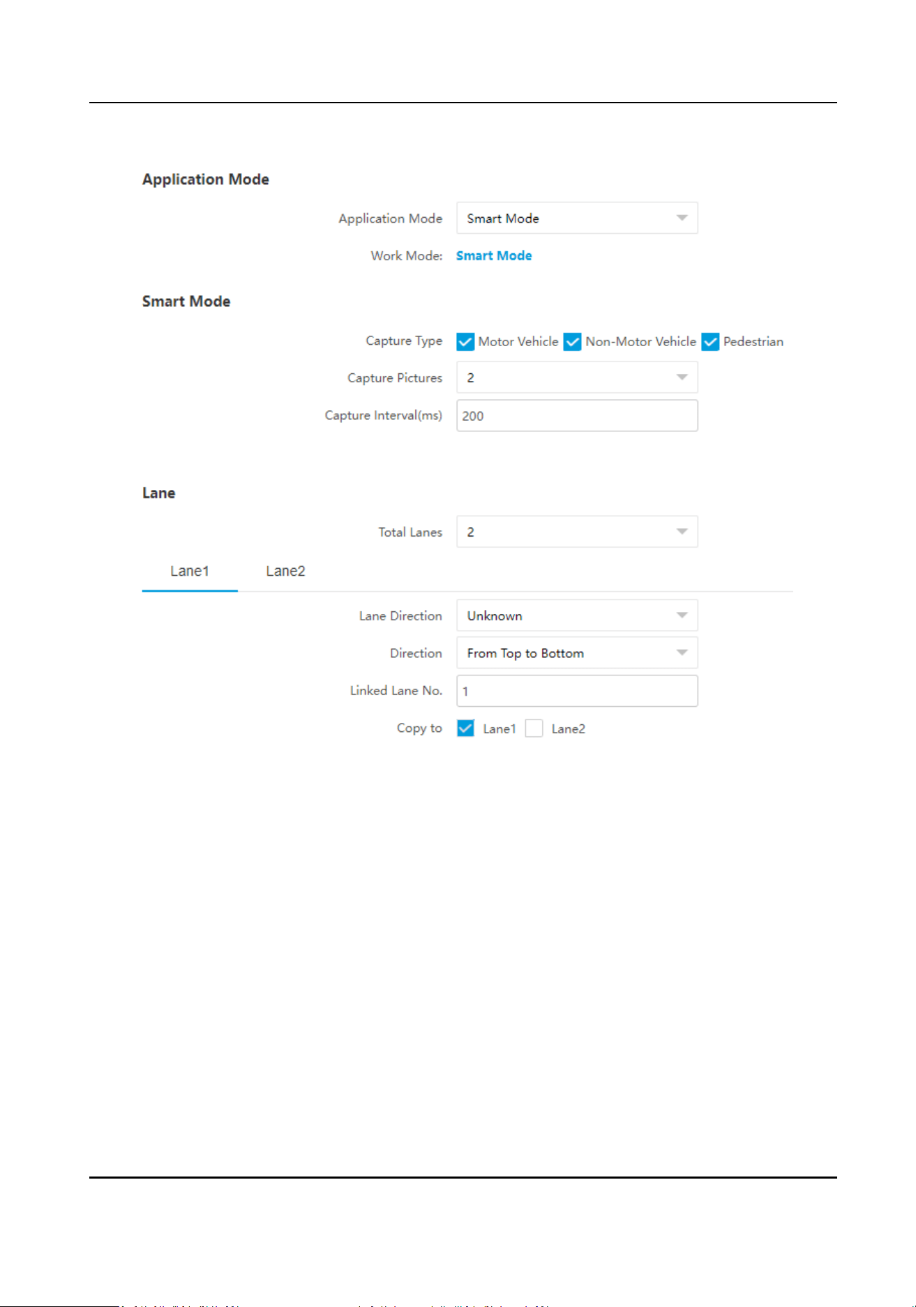
Figure 2-1 Set Smart Monitoring Capture
3.
Set smart mode parameters.
Capture Type
Select the targets to be recognized and captured in the scene.
Capture Pictures
The number of captured picture(s).
Capture Interval
The
me between the adjacent captures.
4.
Set the lane parameters.
Total Lanes
The number of the total lane(s) in the scene.
Lane
Direcon
The guidance direcon of the lane.
Smart Monitoring Camera User Manual
5
Direcon
If you select From Top to Boom, the targets from the approaching direcon towards the
device will be captured. If you select From Boom to Top, the targets from the leaving
direcon away from the device will be captured. If you set the direcon as From Top to
Boom, then the vehicle will be judged as wrong-way driving if it comes from boom to top,
and vice versa.
Linked Lane No.
The corresponding lane No. linked with the current lane. The lane No. will be overlaid on the
captured picture.
Copy to
Check the other lane(s) to copy the same
sengs.
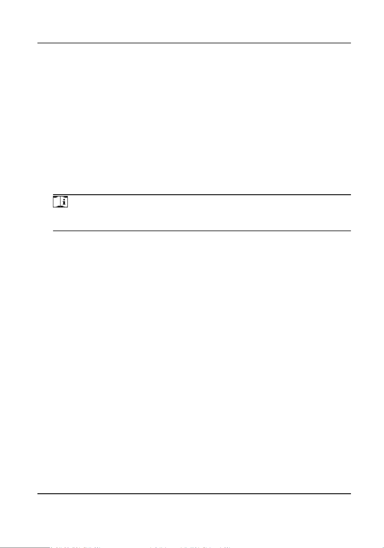
5.
Draw lane lines.
1) Click Draw Lane Line.
Note
The system will capture a picture and use it as the background. You can also check Video
Background to use the live view as the background.
2) Select the default lane lines, trigger line, and right border line, and drag the two end points of
the line or drag the whole line to adjust its
posion according to the actual scene.
3) Oponal: Click Redraw Lane Line to redraw the lines.
4) Click OK.
Smart Monitoring Camera User Manual
6
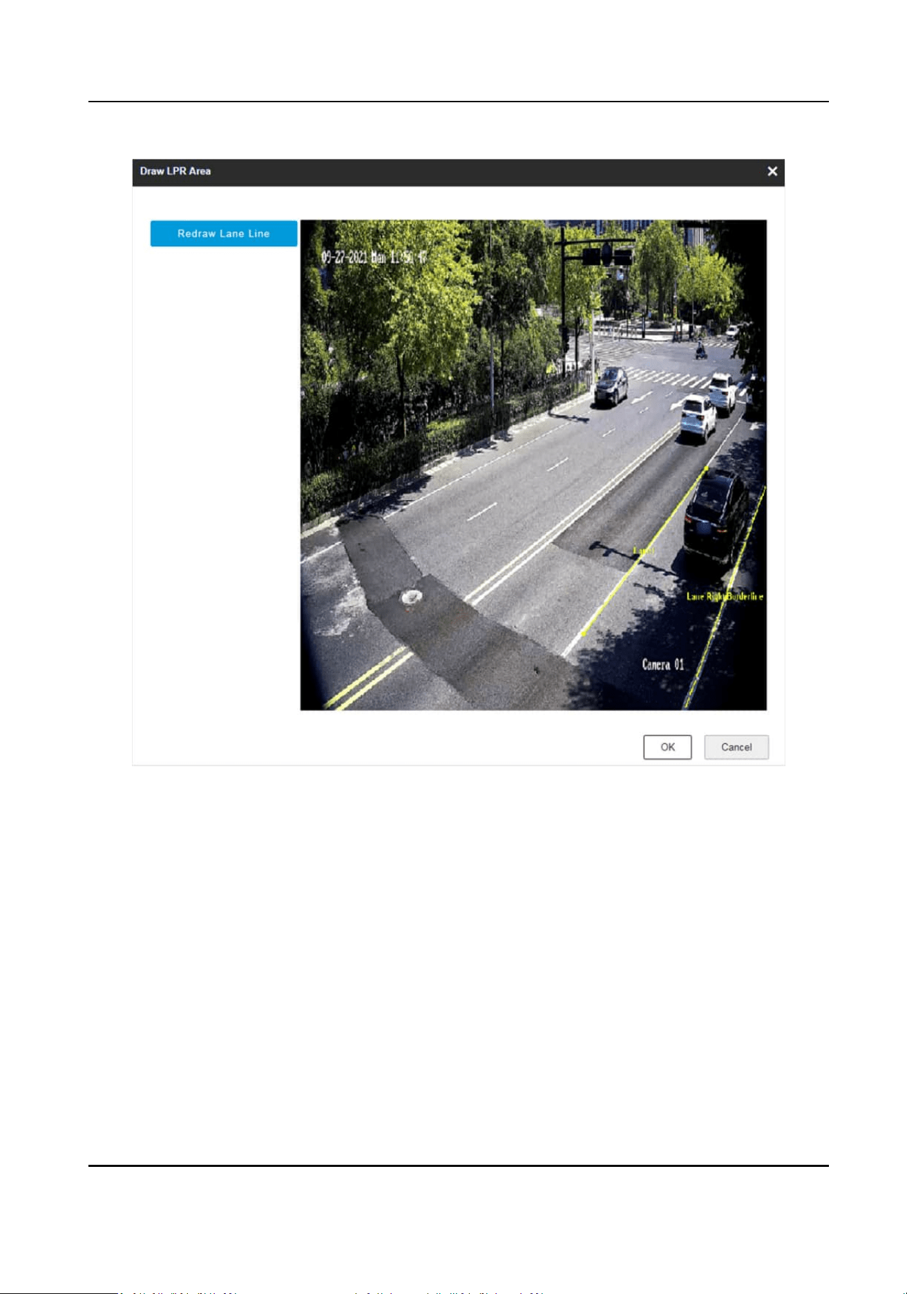
Figure 2-2 Draw Lane Line
6.
Click Save.
2.2 Set Incident
Detecon
The device supports to capture various trac incidents.
Steps
1.
Go to Conguraon → Capture → Applicaon Mode .
2.
Select
Applicaon Mode as Event Detecon.
3.
Click Event Detecon.
4.
Set the capture parameters.
Scene Mode
Smart Monitoring Camera User Manual
7
Select the scene according to the actual device installaon environment.
Close Range Capture
Check it and set Capture Interval. The device will track the target unl one more picture is
captured in close distance according to the capture interval.
5.
Set other parameters, and click Save. Refer to the chapters below for details.
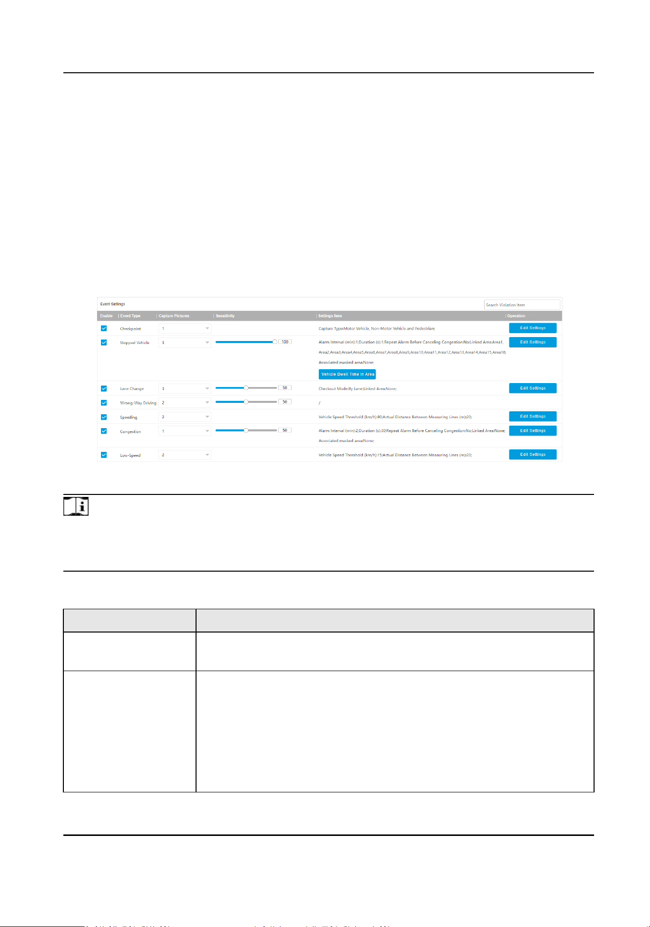
2.2.1 Set Violaon and Incident Detecon
The device can capture pictures of the targets passing the checkpoint in the linked lanes according
to the set rules.
Figure 2-3 Capture Type
Note
For the violaon or incident types supporng linked areas and associated masked areas, the
enabled No. of the linked areas and associated masked areas should be dierent, or the linked
areas cannot take eect.
Table 2-1 Capture Type Descripon
Capture Type Parameters Descripon
Checkpoint Check it and select the number of captured picture(s). Click Edit Sengs
to select Capture Type.
Stopped Vehicle The motor vehicle stops at the posions where parking is forbidden.
Check it, select the number of captured picture(s), and set Sensivity.
The higher the sensivity is, the more easily the violaon will be
captured. Click Edit
Sengs to set the parameters below.
●
Alarm Interval: The interval between two alarms.
●
Duraon: When the vehicle stops at the posions for more than the
set duraon, capture will be triggered.
Smart Monitoring Camera User Manual
8

Capture Type Parameters Descripon
●
Linked Area: Check the lane area(s) to link to the violaon detecon.
All the selected area(s) will apply the set duraon.
●
Associated Masked Area: Check corresponding areas and violaons or
incidents occurred in those areas will not be detected.
Note
●
You can also click Vehicle Dwell Time in Area to set the duraon of
each linked area independently.
●
When the device judges that the current lane is in congeson status,
the stopped vehicles will not be captured.
Lane Change Most part of the vehicle body crosses over the lane line and enters into
another lane. Check it, select the number of captured picture(s), and set
the sensivity. Click Edit Sengs to select Checkout Mode.
●
By Lane: Select it to detect the lane change in the set lane(s).
●
By Area: Select it to detect the lane change in the set area(s).
Wrong-Way Driving The vehicle is driven in the direcon opposite to the guidance direcon
of the lane. Check it, select the number of captured picture(s), and set
the sensivity.
Speeding The motor vehicle is driven in the speed larger than the max. speed limit
of the lane. Check it and select the number of captured picture(s). Click
Edit Sengs to set the parameters below.
●
Vehicle Speed Threshold: The max. speed limit. When the vehicle
speed exceeds the value, speeding capture will be triggered.
●
Actual Distance Between Measuring Lines: The actual distance
between the two measuring lines within which the vehicle speed is
detected.
Congeson The motor vehicles are queuing and the roads are blocked. Check it and
select the number of captured picture(s), and set Sensivity. The higher
the sensivity is, the more easily the congeson will be captured. Click
Edit
Sengs to set the parameters below.
●
Alarm Interval: The interval between two alarms.
●
Duraon: When the congeson lasts for more than the set duraon,
capture will be triggered.
●
Repeat Alarm Before Canceling
Congeson: If you enable the
funcon, alarms will be repeated before the congeson status is
removed.
Smart Monitoring Camera User Manual
9

Capture Type Parameters Descripon
●
Linked Area: Check the lane area(s) to link to the detecon.
●
Associated Masked Area: Check corresponding areas and violaons or
incidents occurred in those areas will not be detected.
Low-Speed The motor vehicle is driven in the speed lower than the min. speed limit.
Check it and select the number of captured picture(s). Click Edit Sengs
to set the parameters below.
●
Vehicle Speed Threshold: The min. speed allowed. When the vehicle
speed is lower than the value, low-speed capture will be triggered.
●
Actual Distance Between Measuring Lines: The actual distance
between the two measuring lines within which the vehicle speed is
detected.
Note
For the violaon and incident types supporng linked areas, if you select linked area(s), select Area
Type of the corresponding linked area.
Figure 2-4 Set Linked Area Type
2.2.2 Set Linked Lane Parameters
You can set the properes and parameters of the linked lanes.
Steps
Note
The linked lane parameters vary with dierent models. The actual device prevails.
1.
Select Total Lanes.
2.
Set the lane parameters.
Smart Monitoring Camera User Manual
10
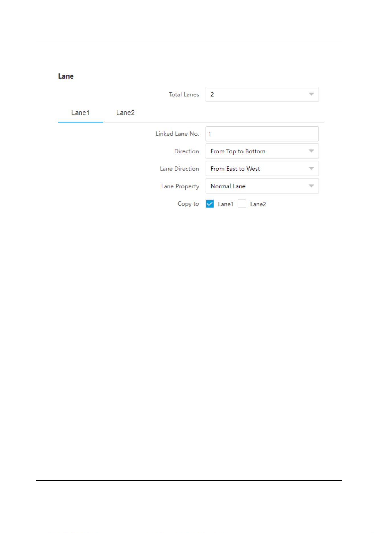
Figure 2-5 Set Lane Parameters
Linked Lane No.
The corresponding lane No. linked with the current lane. The lane No. will be overlaid on the
captured picture.
Direcon
If you select From Top to Boom, the targets from the approaching direcon towards the
device will be captured. If you select From
Boom to Top, the targets from the leaving
direcon away from the device will be captured. If you set the direcon as From Top to
Boom, then the vehicle will be judged as wrong-way driving if it comes from boom to top,
and vice versa.
Lane Direcon
The guidance direcon of the lane.
Lane Property
Select the current lane property according to its usage.
Copy to
Check the other lane(s) to copy the same
sengs.
3.
Click Save.
2.2.3 Draw Lane Lines and
Detecon Areas
Draw lane lines and detecon areas to detect and capture the violaons or incidents in the linked
areas.
Smart Monitoring Camera User Manual
11
Before You Start
Select the linked areas and associated masked areas if needed.
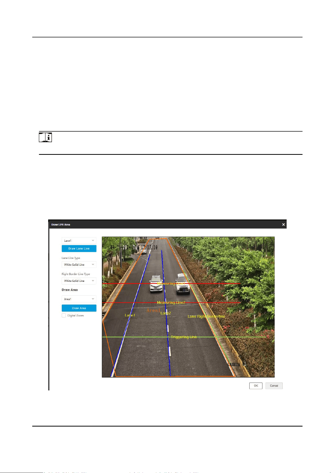
Steps
1.
Click Draw Lane Line.
2.
Select the lane.
3.
Set Lane Line Type and Right Border Line Type.
4.
Select the default lane lines, right border line, triggering line, and measuring lines, and drag the
two end points of the line or drag the whole line to adjust its
posion according to the actual
scene.
Note
Measuring lines are available for speeding and low-speed detecons.
5.
Oponal: Click Draw Lane Line to restore to the default drawing.
6.
Select area and click Draw Area. Click the
le buon of the mouse to draw a rectangular or
polygonal frame, and then click the right buon of the mouse to save the area.
7.
Oponal: Click Draw Area to delete the current area.
8.
Oponal: Check Digital Zoom, and drag the mouse on the live view image to zoom the area in.
Uncheck it to exit from digital zoom.
9.
Click OK.
Figure 2-6 Draw Lane Lines and Detecon Areas
Smart Monitoring Camera User Manual
12
2.2.4 Set Data Collecon
The device supports to detect the trac ow, POS, and other informaon.
Steps
1.
Go to Conguraon → Capture → Applicaon Mode .
2.
Select
Applicaon Mode as Event Detecon.
3.
Click Data Collecon.
4.
Set
trac ow detecon parameters and trac ow informaon overlay.
Set Trac Flow Detecon
Steps
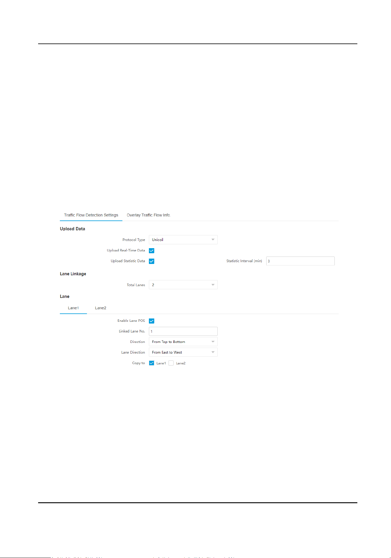
1.
Click
Trac Flow Detecon Sengs.
Figure 2-7 Set Trac Flow Detecon
2.
Set the data upload parameters.
Protocol Type
Unicoil
One coil for each lane.
Double Coil
Two coils for each lane.
Upload Real-Time Data
Smart Monitoring Camera User Manual
13

The device will upload the real-me data to the server. The real-me data include road status,
me, lane No., entrance/exit status, instantaneous speed, space headway, me headway,
congeson trac ow, driving direcon, queue length, congeson level, and intersecon
dedicated data such as the signals when leaving the le turn line, right turn line, going
straight line, and stop line at
intersecons (only supported for mul-coils protocol).
Upload
Stasc Data
The device will upload the stasc data to the server according to the set Stasc Interval.
The stasc data include lane No., trac, average speed, trac state, lane queue length, me
interval of vehicle head, headway distance, lane space occupancy, lane me occupancy,
average delay, and average number of stops.
3.
Set the lane parameters.
1) Select Total Lanes.
2) Click the lane No.
3) Check Enable Lane POS to enable the POS
informaon (feature informaon) collecon of the
lane.
4) Set other parameters.
Linked Lane No.
The corresponding lane No. linked with the current lane. The lane No. will be overlaid on
the captured picture.
Direcon
If you select From Top to Boom, the targets from the approaching direcon towards the
device will be captured. If you select From
Boom to Top, the targets from the leaving
direcon away from the device will be captured. If you set the direcon as From Top to
Boom, then the vehicle will be judged as wrong-way driving if it comes from boom to
top, and vice versa.
Lane Direcon
The guidance direcon of the lane.
5)
Oponal: Check lane(s) to copy the parameters of the current lane to other lane(s).
4.
Draw lane lines and virtual coil areas.
1) Click Draw Lane Line.
2) Select the lane.
3) Select the default lane lines and right border line, and drag the two end points of the line or
drag the whole line to adjust its
posion according to the actual scene.
4) Oponal: Click Draw Lane Line to restore to the default drawing.
5) Click Draw Virtual Coil A/B/C... to draw the virtual coil areas.
Smart Monitoring Camera User Manual
14
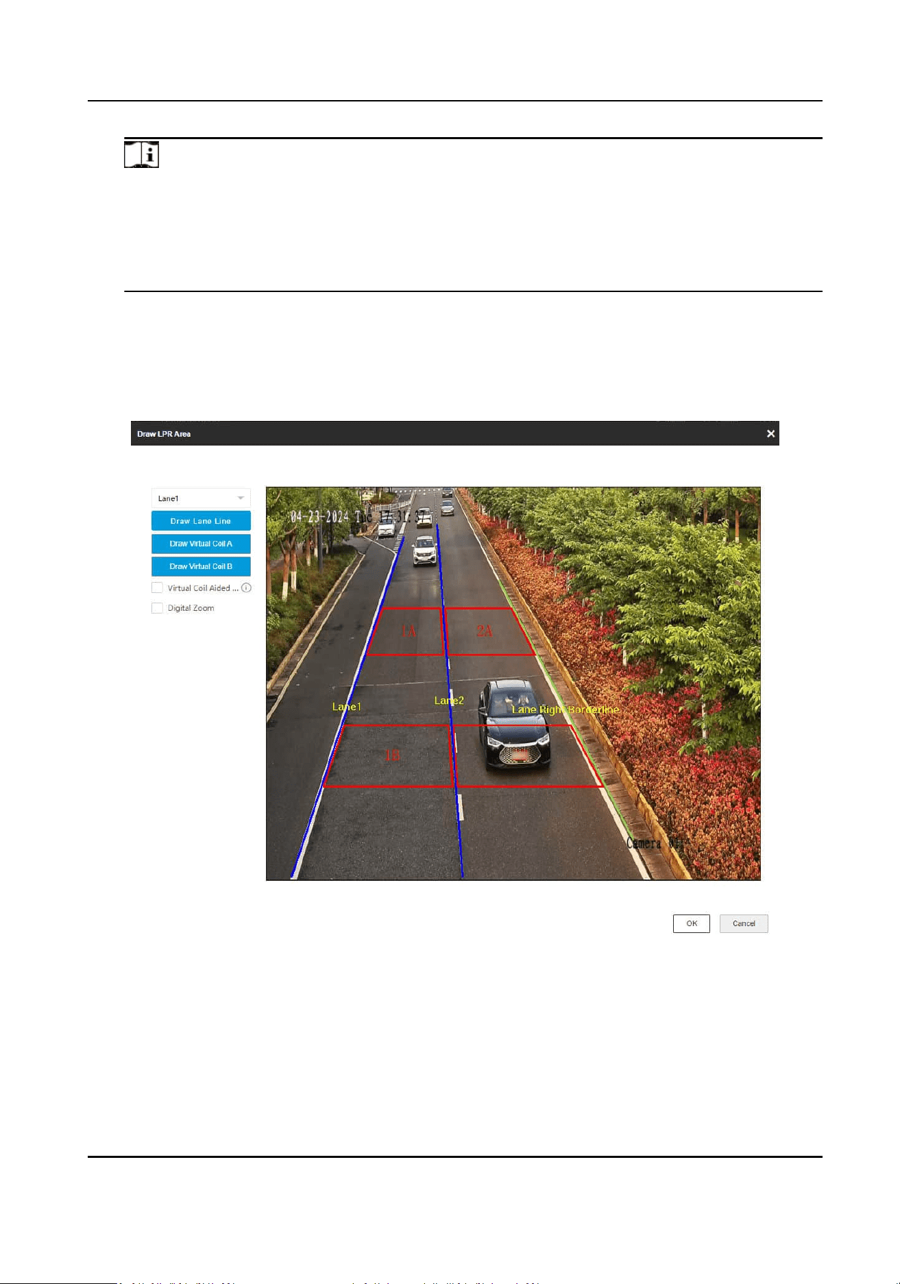
Note
●
Click the le buon of the mouse to locate the vertexes of the virtual coil area on the live
view image, and click the right buon of the mouse to nish the drawing.
●
It is recommended that the virtual coil height is half of the small-sized vehicle length and
the width is the lane width.
●
The virtual coils should be set at the posions where the radar and video can both detect.
6) Oponal: You can check Virtual Coil Aided Drawing and draw the coils of lane 1. Then the
coils of the other lanes will be generated
automacally.
7) Oponal: Check Digital Zoom, and drag the mouse on the live view image to zoom the area
in. Uncheck it to exit from digital zoom.
8) Click OK.
Figure 2-8 Draw Lane Lines and Virtual Coils Areas
5.
Click Save.
Smart Monitoring Camera User Manual
15
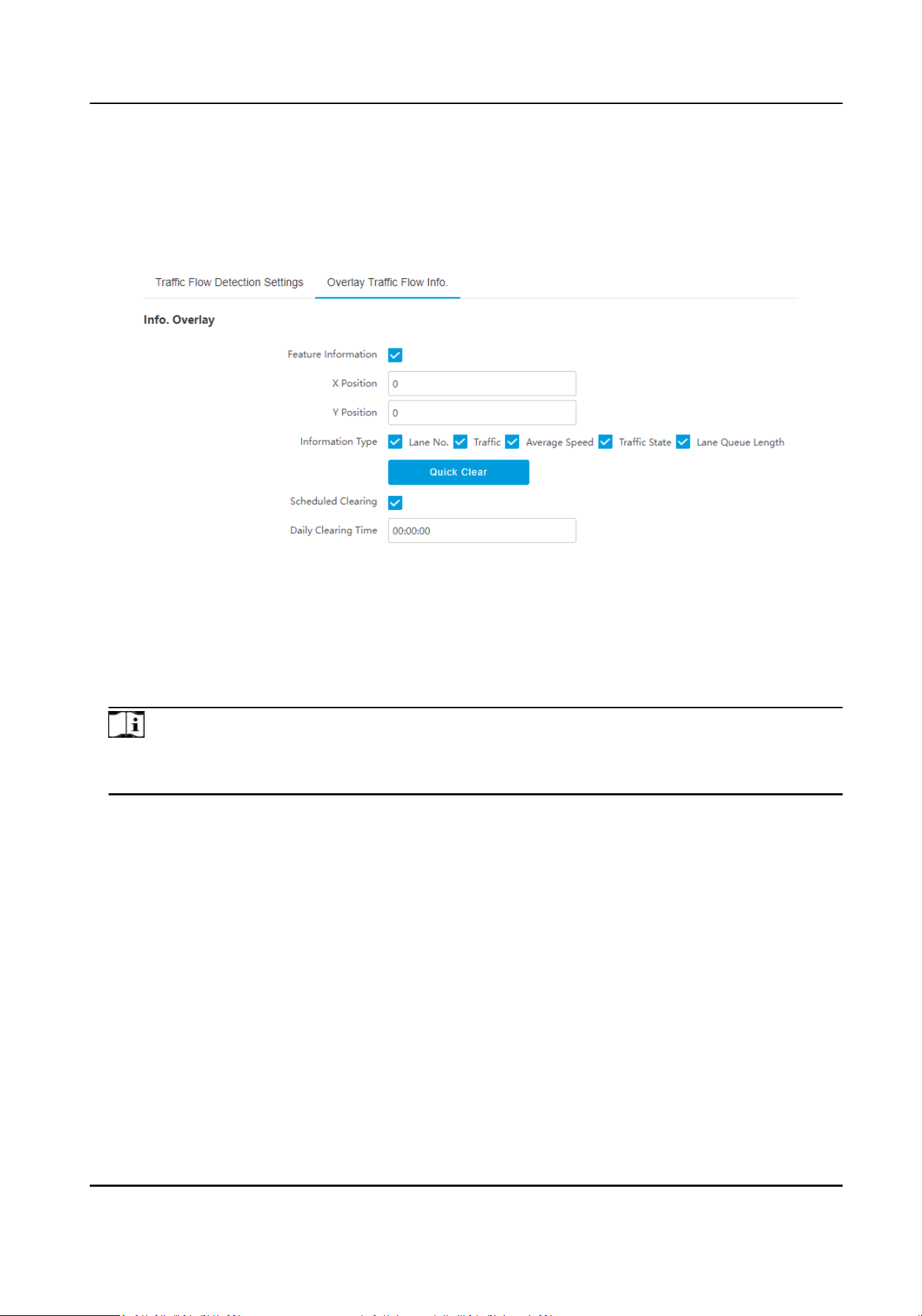
Set Trac Flow Informaon Overlay
Steps
1.
Click Overlay
Trac Flow Info.
Figure 2-9 Set
Trac Flow Informaon Overlay
2.
Set feature informaon overlay.
1) Check Feature Informaon to overlay the feature informaon on the video stream and
display on the live view image.
2) Enter X
Posion and Y Posion to display on the image.
3) Select Informaon Type to overlay on the image.
Note
You can display the trac ow (le turn ow, right turn ow, and going straight ow), and coil
ow (coil 1 or coil 2 ow) on the live view image.
3.
Oponal: Clear the trac ow stascs data if needed.
-
Click Quick Clear to clear all the
trac ow stascs data quickly.
-
If you want to clear the trac ow stascs data at the xed me daily, check Scheduled
Clearing and set Daily Clearing Time.
4.
Click Save.
2.3 Set License Plate
Recognion System Capture
If you want to trigger capture of the passing vehicles and recognize the license plate numbers, set
license plate recognion system capture.
Steps
1.
Go to Conguraon → Capture → Applicaon Mode .
2.
Select
Applicaon Mode as License Plate Recognion System.
Smart Monitoring Camera User Manual
16
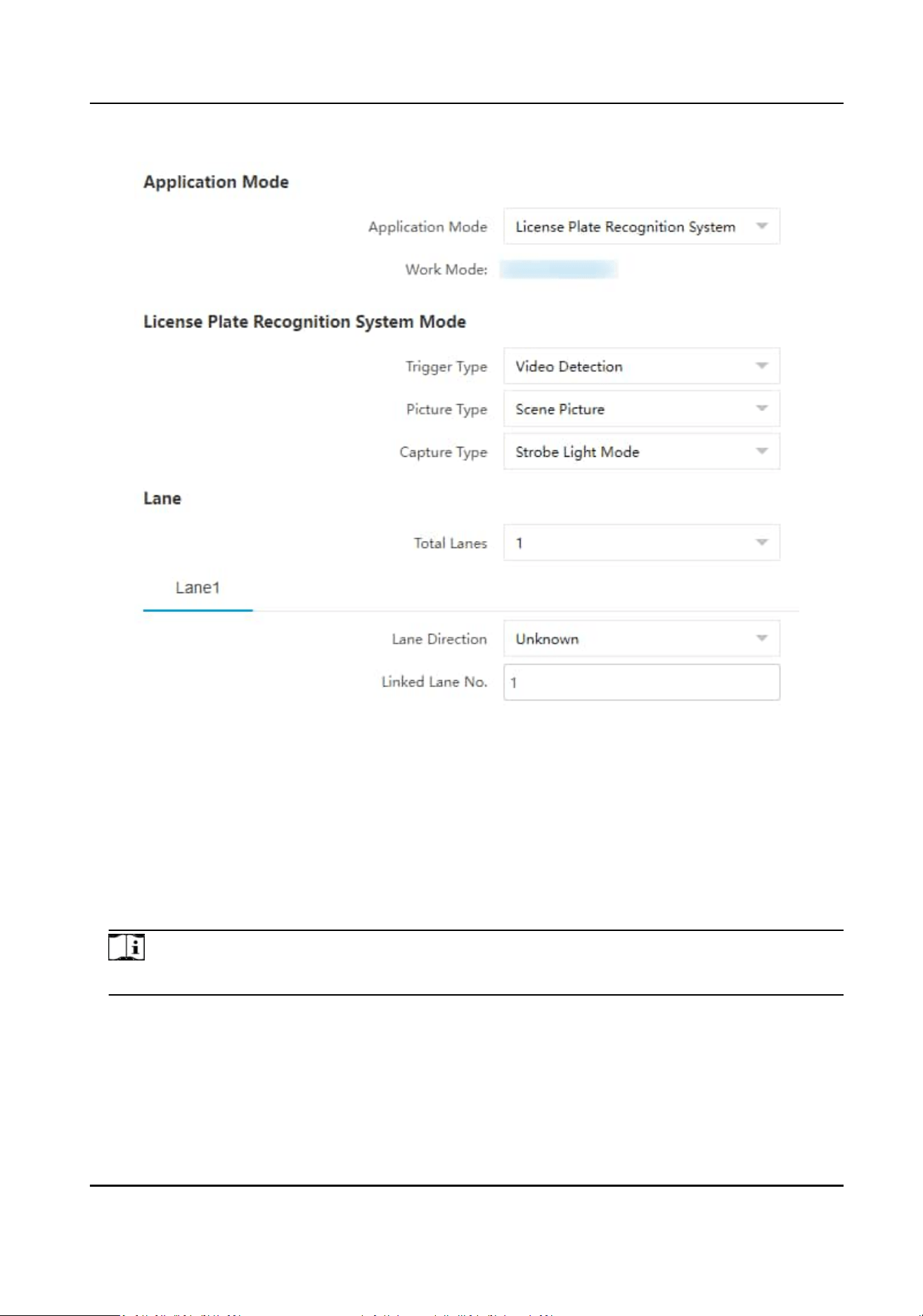
Figure 2-10 Set License Plate Recognion System
3.
Select Trigger Type.
Video Detecon
The passing vehicles will be recognized via videos. The capture mode is recommended as
Strobe Light Mode.
I/O Coil
Select it when the device has been connected to I/O signal.
Note
The trigger types vary with dierent models. The actual device prevails.
4.
Select Picture Type.
Scene Picture
Only one passing vehicle picture will be output.
5.
Set the lane parameters.
Total Lanes
Smart Monitoring Camera User Manual
17

The number of the total lane(s) in the scene.
Lane Direcon
The guidance direcon of the lane.
Linked Lane No.
The corresponding lane No. linked with the current lane. The lane No. will be overlaid on the
captured picture.
6.
Set I/O trigger parameters if you select Trigger Type as I/O Coil.
I/O Trigger Default Status
Capture is triggered according to the level signal status. If you select Falling Edge, the device
will trigger capture at the moment that the high level falls to low level. If you select Rising
Edge, the device will trigger capture at the moment that the low level rises to high level.
Linked I/O No.
When the coil detects that there is a vehicle passing, a rising or falling edge signal is sent to
the linked I/O of the device to trigger capture.
7.
Draw lane lines.
1) Click Draw Lane Line.
2) Select the default lane lines, trigger line, and right border line, and drag the two end points of
the line or drag the whole line to adjust its
posion according to the actual scene.
3) Click OK.
Note
It is recommended to draw the trigger line at the posion which is 1/3 to 1/4 of the lane line.
The license plate pixel should be between 120 to 180 at the capture posion.
Smart Monitoring Camera User Manual
18
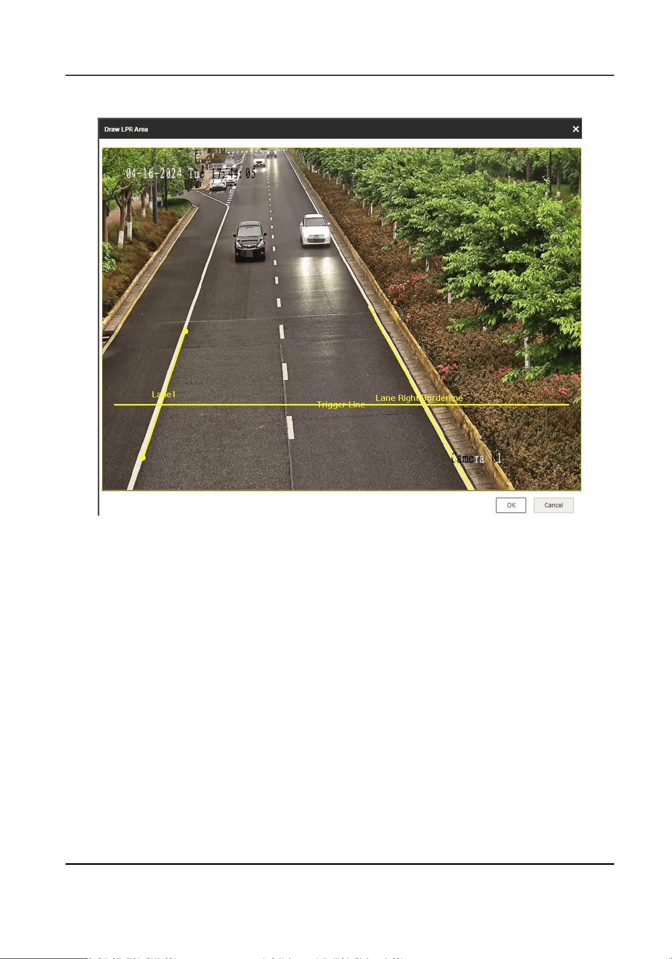
Figure 2-11 Draw Lane Line
8.
Click Save.
Smart Monitoring Camera User Manual
19
Chapter 3 Capture Parameters Conguraon
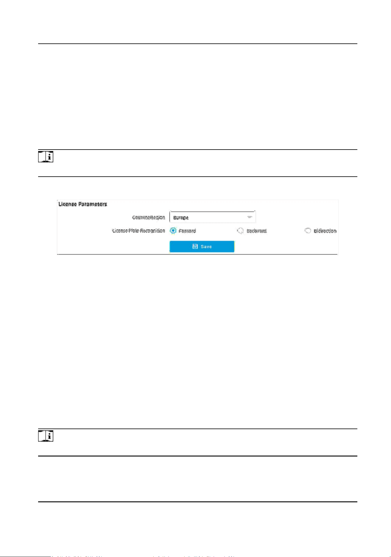
3.1 Set License Plate Recognion Parameters
When there are vehicles of dierent types passing from dierent direcons, set the license plate
recognion parameters.
Steps
Note
The supported parameters vary with dierent models. The actual device prevails.
1.
Go to Conguraon → Capture → Capture Parameters → License Parameters .
Figure 3-1 Set License Plate Recognion Parameters
2.
Set Country/Region according to the actual needs.
3.
Select License Plate Recognion.
-
Select Forward when license plates of vehicles from the approaching
direcon need to be
recognized.
-
Select Backward when license plates of vehicles from the leaving direcon need to be
recognized.
-
Select Bidirecon when license plates of vehicles from both the approaching direcon and
the leaving
direcon need to be recognized.
4.
Click Save.
3.2 Set Supplement Light Parameters
Supplement light can enhance the image stabilizaon and adjust the brightness and color
temperature.
Steps
Note
The supported parameters vary with dierent models. The actual device prevails.
1.
Go to Conguraon → Capture → Capture Parameters → Supplement Light Parameters .
Smart Monitoring Camera User Manual
20
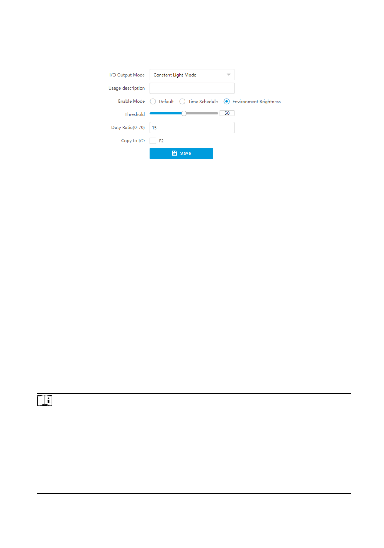
Figure 3-2 Set Supplement Light Parameters
2.
Select the I/O and set the usage.
I/O Output Mode
Constant Light Mode
The constant light supplements light for the scene.
Usage Descripon
Enter the usage descripon of the constant light.
3.
Set the supplement light control mode.
-
Select Default to disable the supplement light.
-
Select Time Schedule when you want the supplement light to be enabled during a xed me
period. Set the start me and end me.
-
Select Environment Brightness when you want the supplement light to be controlled by
detecng the surroundings brightness automacally. Set the brightness threshold. The higher
the threshold is, the harder the supplement light can be enabled.
4.
Oponal: Select other I/O(s) to copy the same sengs.
5.
Click Save.
3.3 Set Vehicle Feature Parameters
Set vehicle feature parameters if you need to detect the vehicle features of the passing vehicle.
Steps
Note
The parameters vary with dierent models. The actual device prevails.
1.
Go to Conguraon → Capture → Capture Parameters → Vehicle Feature → Vehicle Feature .
2.
Check the motor and non-motor vehicle features that needed to be detected, and set the
corresponding
sensivity.
3.
Click Save.
Smart Monitoring Camera User Manual
21
3.4 Set Body Picture Mang
Set body picture mang rst if you need to upload body and vehicle pictures to the plaorm.
Steps
Note
The funcon varies with dierent models. The actual device prevails.
1.
Go to Conguraon → Capture → Capture Parameters → Vehicle Feature → Body Picture
Mang .
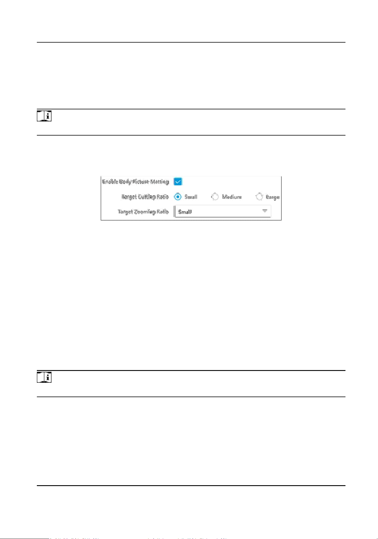
2.
Check Enable Body Picture
Mang.
Figure 3-3 Set Body Picture Mang
3.
Set body picture mang parameters according to the actual needs.
4.
Click Save.
Result
If the device is level 1 armed, the mang pictures will be uploaded to this device directly. If the
device is level 2 armed, the mang pictures will be saved to the SD/TF card and uploaded to a
level 2 armed device.
3.5 Set Picture
Composion
You can enable the picture composion to composite several pictures into one to make it
convenient to view the violaon captured pictures.
Steps
Note
Funcons and parameters vary with dierent models. The actual device prevails.
1.
Go to Conguraon → Capture → Capture Parameters → Image Encoding and Composion →
Checkpoint Image Composion/Violaon Picture Composion .
Smart Monitoring Camera User Manual
22
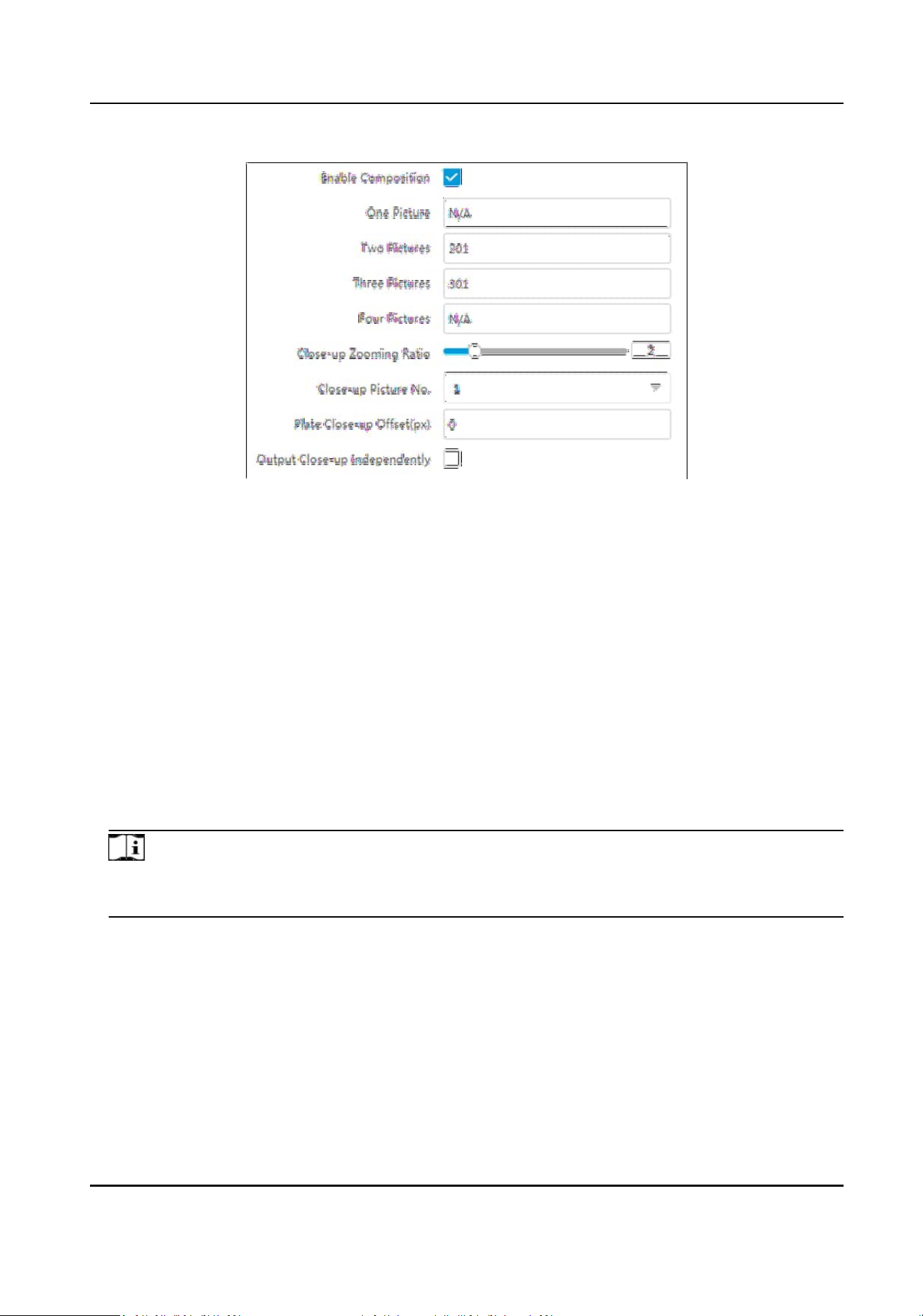
Figure 3-4 Set Picture Composion
2.
Check Enable Composion.
3.
Set composion types for dierent picture quanes.
4.
Set other composion parameters.
Close-up Zooming
Rao
The higher the value is, the larger the close-up is.
Close-up Picture No.
It is the picture where the close-up comes from.
Plate Close-up Oset
The default value is 0, which is recommended to be adopted. The device can capture close-up
pictures according to the set oset when no license plate is recognized.
5.
Oponal: Check Output Close-up Independently to output close-up pictures independently
when the picture composion is not enabled.
Note
Enabling composion and outpung close-up independently funcons conict with each other.
You can only enable one.
6.
Click Save.
3.6 Set
Informaon Overlay
3.6.1 Set Single Picture Overlay
If you want to overlay informaon on the captured single pictures, set capture overlay.
Smart Monitoring Camera User Manual
23
Steps
Note
The supported parameters vary with dierent models. The actual device prevails.
1.
Go to Conguraon → Capture → Capture Parameters → Text Overlay .
2.
Select single picture channel.
3.
Check Capture Picture Overlay.
Figure 3-5 Set Single Picture Overlay
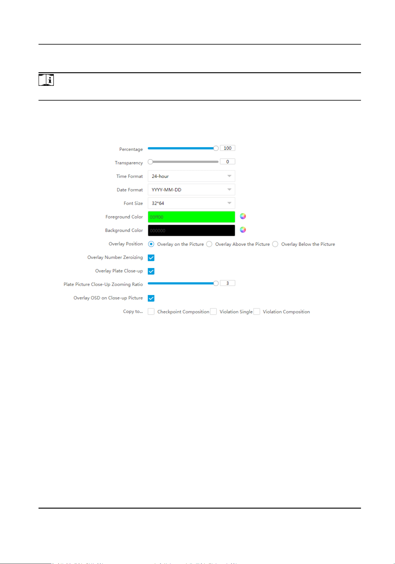
4.
Set the percentage, front size, color, overlay posion, etc.
Percentage
It is the percentage that the overlaid
informaon occupies on the picture. For example, if you
set the percentage to 50, the overlaid informaon in a row will occupy up to half of the image
width, and the excess content will be overlaid from a new line.
Transparency
It is the
condion of viewing the live view image through the overlaid informaon.
Overlay Number Zeroizing
When the overlaid number digits are smaller than the xed digits, 0 will be overlaid before
the overlaid number. E.g., the xed digits for lane No. is 2. If the lane No. is 1, 01 will be
overlaid on the picture.
Overlay Plate Close-up
Smart Monitoring Camera User Manual
24

Check it to overlay license plate close-up pictures on the captured pictures. Set Plate Picture
Close-Up Zooming Rao to adjust the close-up picture size.
Overlay OSD on Close-up Picture
Check it to overlay the OSD informaon on the close-up pictures.
5.
Oponal: Check the other channel(s) to copy the same sengs.
6.
Select the overlay informaon from the list.
Note
The overlay informaon varies with dierent models. The actual device prevails.
7.
Set the overlay informaon.
View Default Type You can view the default overlay informaon.
Set Type You can edit the type.
Set Overlay
Informaon
For some informaon types, you can edit the detailed informaon.
Set Overlay Posion If you check it, the current informaon will be displayed from a new
line.
Set Space Edit the number of space between the current informaon and the
next one from 0 to 255. 0 means there is no space.
Set Line Break
Characters
Edit the number of characters from 0 to 100 between the current
informaon line and the previous informaon line. 0 means no line
break.
Adjust overlay
sequence
Click / to adjust the display sequence of the overlay
informaon.
8.
Click Save.
3.6.2 Set Composite Picture Overlay
If you want to overlay informaon on the composite pictures, set composite picture overlay.
Steps
Note
The supported parameters vary with dierent models. The actual device prevails.
1.
Go to Conguraon → Capture → Capture Parameters → Text Overlay .
2.
Select composite picture channel.
3.
Check Capture Picture Overlay.
Smart Monitoring Camera User Manual
25
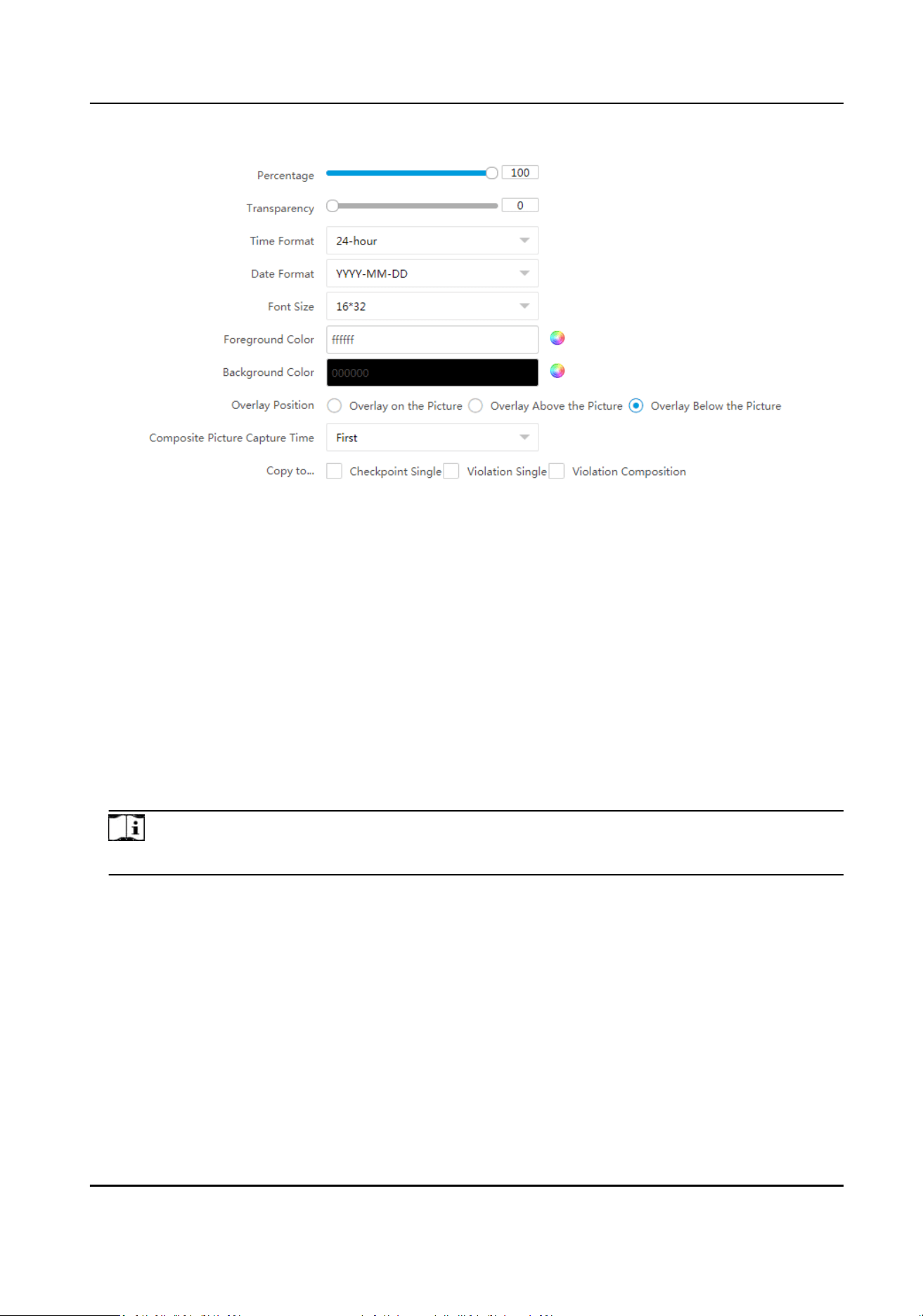
Figure 3-6 Set Composite Picture Overlay
4.
Set the font size, color, overlay posion, etc.
Percentage
It is the percentage that the overlaid informaon occupies on the picture. For example, if you
set the percentage to 50, the overlaid informaon in a row will occupy up to half of the image
width, and the excess content will be overlaid from a new line.
Transparency
It is the
condion of viewing the live view image through the overlaid informaon.
Composite Picture Capture Time
The capture me of the selected picture sequence will be overlaid on the composite picture.
5.
Oponal: Check the other channel(s) to copy the same sengs.
6.
Select the overlay informaon from the list.
Note
The overlay informaon varies with dierent models. The actual device prevails.
7.
Set the overlay informaon.
View Default Type
You can view the default overlay informaon.
Set Type You can edit the type.
Set Overlay
Informaon
For some informaon types, you can edit the detailed informaon.
Set Overlay Posion If you check it, the current informaon will be displayed from a new
line.
Set Space Edit the number of space between the current informaon and the
next one from 0 to 255. 0 means there is no space.
Smart Monitoring Camera User Manual
26
Set Line Break
Characters
Edit the number of characters from 0 to 100 between the current
informaon line and the previous informaon line. 0 means no line
break.
Adjust overlay
sequence
Click / to adjust the display sequence of the overlay
informaon.
8.
Click Save.
3.7 Set Image Encoding Parameters
If the captured pictures are not clear, set the resoluon of the captured pictures and the picture
size.
Steps
1.
Go to
Conguraon → Capture → Capture Parameters → Image Encoding and Composion →
Image Encoding .
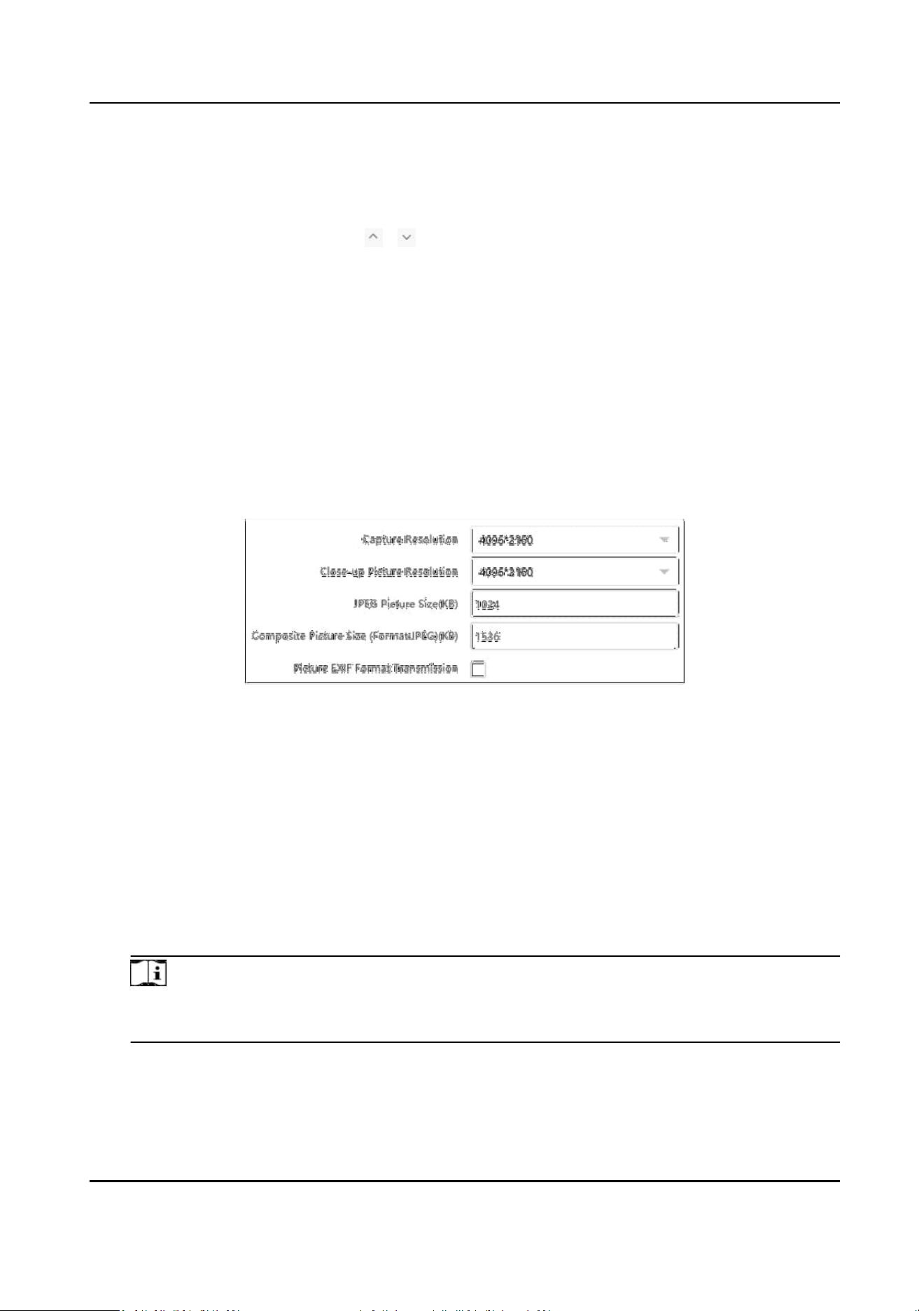
Figure 3-7 Set Image Encoding Parameters
2.
Select Capture Resoluon.
3.
Select Close-up Picture
Resoluon.
4.
Enter the picture size.
JPEG Picture Size
The size of the compressed captured picture. The actual size is related to the scene
complexity.
Composite Picture Size
The size of the compressed composite picture. The actual size is related to the scene
complexity.
Note
Only the device supporng picture composion supports composite picture size sengs. The
actual device prevails.
Picture EXIF Format Transmission
The captured pictures will be transmied in the EXIF format.
Smart Monitoring Camera User Manual
27
5.
Click Save.
3.8 Set Capture Schedule
You can set the schedule for the violaon behavior capture or checkpoint capture if needed.
Steps
1.
Go to Conguraon → Capture → Capture Parameters → Capture Schedule .
2.
Click
to set the capture schedule according to the actual needs.
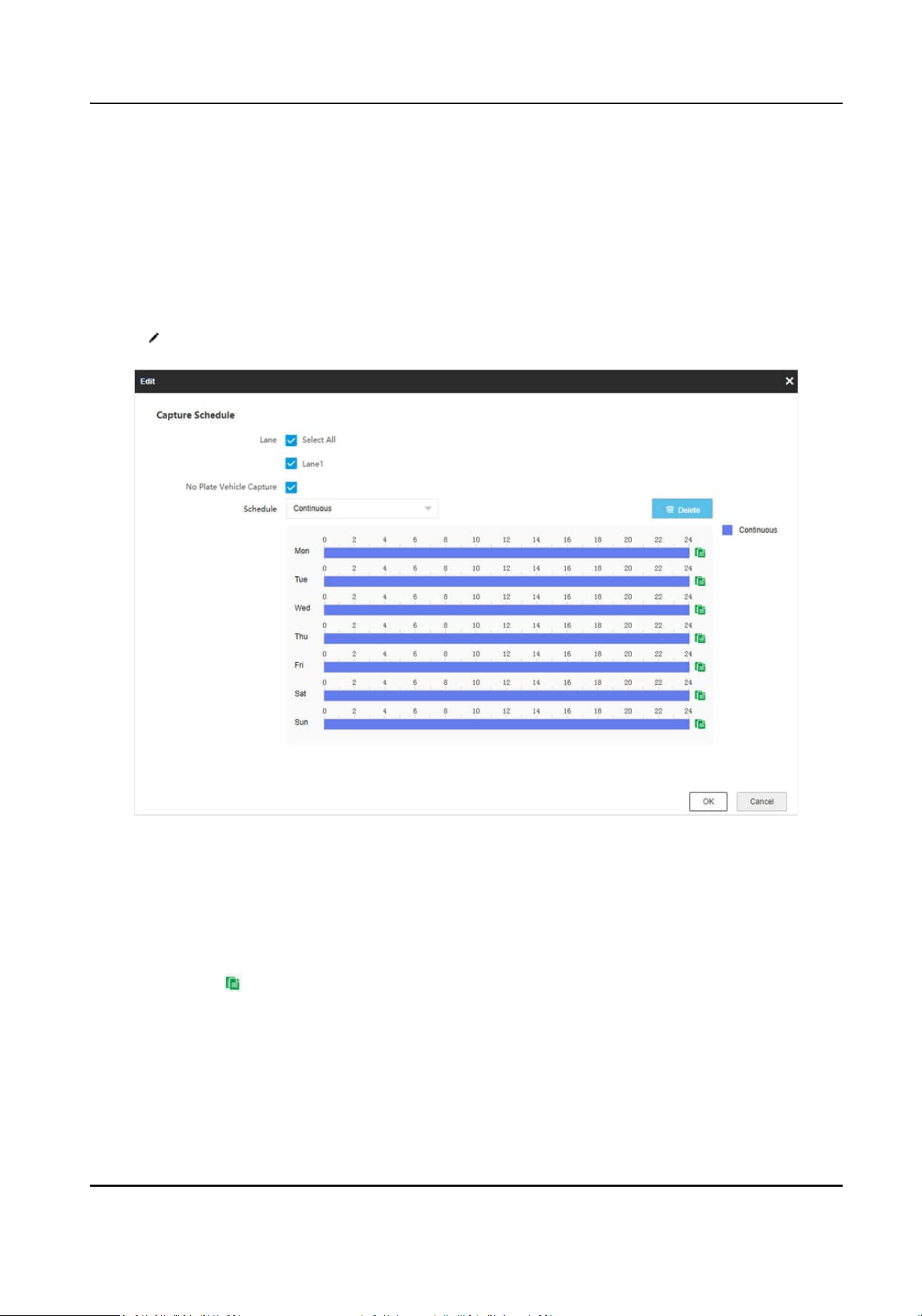
Figure 3-8 Set Capture Schedule
3.
Select Lane.
4.
Oponal: Check No Plate Vehicle Capture according to the actual needs.
5.
Adjust the
me period.
-
Click on the selected
me period, and enter the desired value. Click Save.
-
Click on the selected me period. Drag the both ends to adjust the me period.
6.
Oponal: Click to copy the same sengs to other days.
7.
Click OK.
8.
Oponal: Check Upload to Mailbox to email the capture schedule to the user.
9.
Click Save.
Smart Monitoring Camera User Manual
28
3.9 Set Captured Image Parameters
Set the parameters of captured images to raise the image quality.
Steps
Note
The funcon varies with dierent models. The actual device prevails.
1.
Go to Conguraon → Capture → Capture Images → Image Parameters .
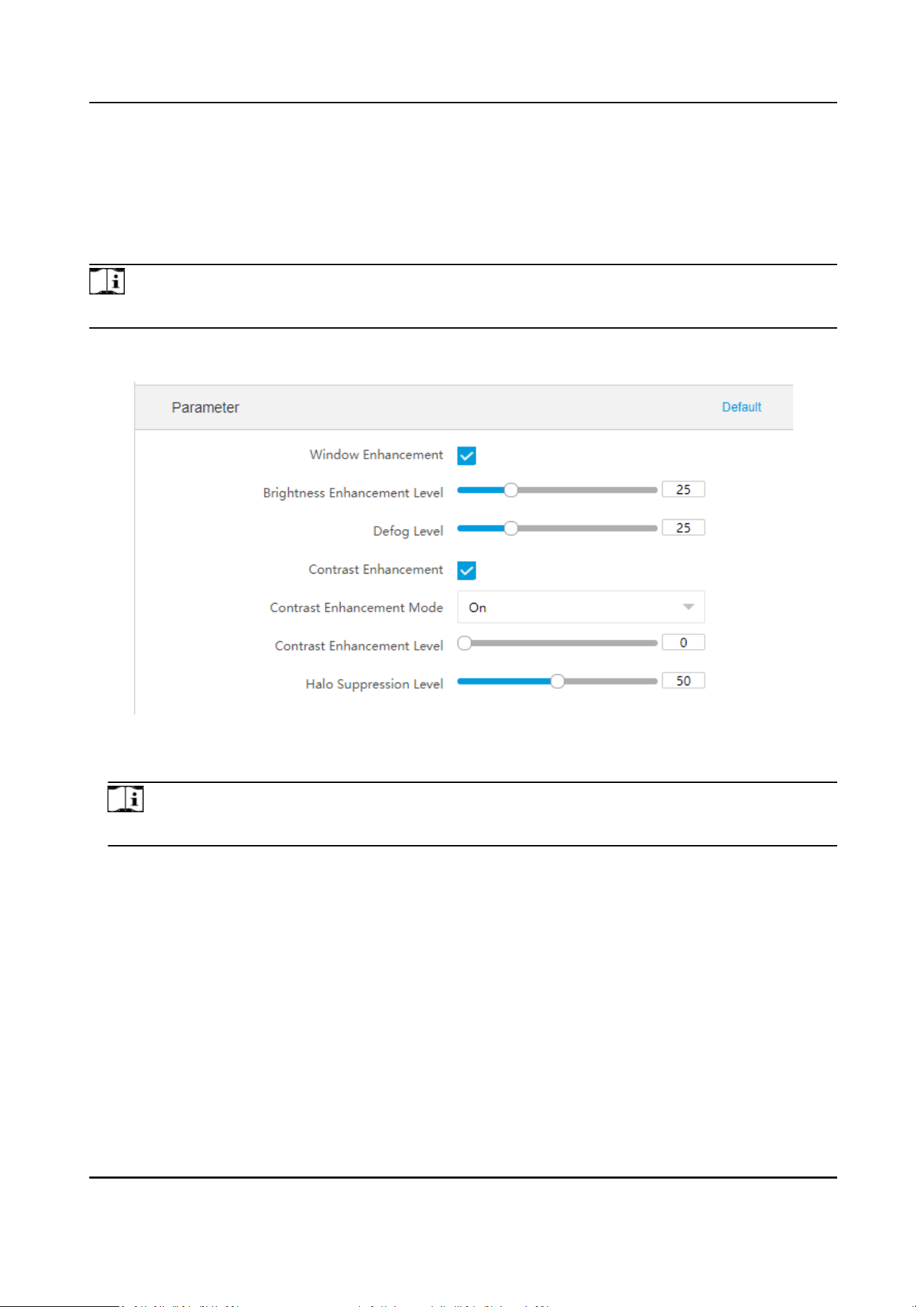
Figure 3-9 Set Captured Image Parameters
2.
Set the captured image parameters.
Note
You can click Default to restore all the set parameters to the default sengs.
Window Enhancement
In front light or back light scene, the ash light may not pass through the vehicle window, or
the image eect of the window is bad caused by the light. In this condion, you can check
Window Enhancement. The higher the Brightness Enhancement Level is, the brighter the
window image is. The higher the Defog Level is, the
beer the permeability of the window
image is.
Contrast Enhancement
Check Contrast Enhancement to capture clearer images. Select Contrast Enhancement
Mode, and set corresponding parameters.
Smart Monitoring Camera User Manual
29
Contrast Enhancement Mode Descripon
On The contrast enhancement mode is always enabled.
Time The contrast enhancement mode is enabled during the set
start me and end me. In other me, it is disabled.
Brightness The contrast enhancement mode is enabled according to the
brightness of the surroundings. In this case, you can set
Brightness Level.
Contrast Enhancement Level
The higher the level is, the more the contrast is enhanced.
Halo Suppression Level
Halo suppression is to suppress the halo of the vehicle headlights. The higher the level is,
the more the halo is suppressed.
3.10 Set ICR
ICR adopts mechanical IR lter to lter IR in the day to guarantee the image eect, and to remove
the IR
lter at night to guarantee full-spectrum rays can get through the device.
Steps
Note
For the device supporng black and white mode at night, when the day-night mode is night, and
Black and White Mode at Night has been enabled in Conguraon → Video → Camera Parameter
→ Camera Parameter → General Parameter , the image displays as black and white. When Black
and White Mode at Night is disabled, the image displays as color.
1.
Go to Conguraon → Capture → Capture Images → ICR .
2.
Select ICR Mode.
Auto Switch
The ICR mode will switch to day or night mode automacally according to the
surrounding light condions. When the surrounding light is sucient and
higher than the set Threshold, the ICR mode will switch to day. When the
surrounding light is
insucient and lower than the set Threshold, the ICR
mode will switch to night.
Manual
Switch
Select Day-night Mode to switch to the day or night manually.
Schedule
Switch
Set Day-night Mode, Start Time, and End Time to switch to the day or night
mode only during the set me period.
3.
Click Save.
Smart Monitoring Camera User Manual
30
3.11 Debug
Note
The debug conguraons below are only provided to debug the device by the professionals.
3.11.1 Debug Device
You can enable the funcons to debug the device.
Steps
1.
Go to Conguraon → Capture → Advanced → System Service .
2.
Check the debug
informaon according to your needs.
Note
The supported parameters vary with dierent models. The actual device prevails.
Enable Algorithm POS Informaon Debug
The algorithm POS informaon will be overlaid on the playback image when you play back
the video with the dedicated tool.
Enable Posioning Frame Debug
The posioning frames of vehicle bodies and license plates will be overlaid on the captured
pictures.
Enable Closed
Posioning Frame
The boom lines of the posioning frames on the captured pictures will be displayed. The
frames will be closed.
Enable LPR Area Frame
The LPR area frames on the captured pictures will be displayed.
Note
The funcon is only valid in the trigger modes of checkpoint single I/O and RS-485 radar, and
manual capture. In these modes, the license plate may not be included in the LPR area, and
the LPR rate is low. To solve the problem, you can enable the funcon to add a green frame
on the captured picture to check whether the license plate is included in the LPR area.
LPR Area Frame Y-Direcon Deviaon
If the license plate is not included in the LPR area frame, adjust the LPR area frame posion in
the
Y-direcon by pixel. Enter the deviaon pixel in the text eld. The value = image height ×
(deviaon distance/100). Set the value according to the actual needs. Range: -100% to 100%.
The LPR area frame moves up if the value is negave, and it moves down if the value is
posive.
Smart Monitoring Camera User Manual
31
Enable License Plate Frame
The license plate frames will be overlaid on the captured pictures.
Enable Mul-Way Upload
Data will be uploaded in mulple set ways simultaneously.
Enable Lane Line Debug
Check it to overlay lane lines on a captured picture.
3.
Click Save.
3.11.2 Vehicle Capture and Recognion Service
Set the vehicle capture and recognion service to debug the device.
Steps
Note
The funcon varies with dierent models. The actual device prevails.
1.
Go to Conguraon → Capture → Advanced → Vehicle Capture and Recognion Service .
2.
Click Checkpoint Parameters or Violaon Parameters to set the corresponding parameters.
3.
Check the service(s) according to your needs.
Note
The supported services vary with dierent models. The actual device prevails.
Filter Checkpoint Capture of Same Vehicle
It is used to debug the device with the same vehicle. When the same vehicle is triggered
many
mes during a short period in the scene, the checkpoint pictures of the vehicle will not
be captured. Set Eecve Time of Filtering to lter the vehicle during the set me.
Capture Frame Priority Mode
Check it to adopt license plate recognion results that processed by the single frame
recognion algorithm.
Enable License Plate Supplementary Recognion
Check it and the device will enable license plate recognion algorithm again to re-recognize
the unrecognized license plates.
Do Not Capture Reverse-driving Vehicle
The reverse-driving vehicles will not be captured. For example, if you need to capture the
vehicles driven from the west to the east, enable the
funcon and the vehicles driven from
the east to the west will not be captured.
Enable SIRA Protocol
Smart Monitoring Camera User Manual
32

For the device supporng Middle East SIRA protocol, check it to enable the protocol. Then
the license plates will be overlaid on the captured pictures according to the license plate
types of the Middle East license plate recognion library.
Enable Video Electric Alarm Steering Flow
In video analysis E-police applicaon mode, you can enable the funcon to make stascs
about the trac ow of le turn and right turn at the intersecon and upload the stascs
data to the connected plaorm.
Enable Non-Motor Vehicle Flow Stascs
Check it to enable the non-motor vehicle ow stascs.
Enable Stascs Integral Upload
The device will upload data at every integral minute according to the set me interval under
the
collecon mode. For example, if the set me interval is 2, the device will upload data at
8:00:00, 8:02:00, 8:04:00, etc.
Filter Two-Wheelers Without License
Check it to not capture the two-wheelers without license plates.
Enable ANR
Enable ANR (Automac Network Replenishment) to save the videos in the condion of
network disconnecon, and synchronize data aer the network is recovered.
Add No. Aer Violaon Type
The No. of the captured pictures will be added aer the overlaid violaon type on the
pictures.
Filter
Violaon Capture of Motorcycle
The violaon pictures of motorcycles will not be captured.
Disable Non-Motor Vehicle Speed Detecon
The speeds of non-motor vehicles will not be detected.
VCA Alarm for Target Picture Mang
If target picture mang is enabled, the alarms will be triggered and the maed target
pictures will be uploaded via VCA protocol.
4.
Click Save.
3.11.3 Set Image Format
You can enable smartJPEG which can save the storage space without inuencing the resoluon.
Steps
1.
Go to
Conguraon → Capture → Advanced → Image Service .
2.
Check smartJPEG.
3.
Set image quality according to your needs.
Smart Monitoring Camera User Manual
33
Note
The higher the value is, the beer the image quality is.
4.
Oponal: Set Expansion Rao of License Plate Image to expand the cutout scale of license plate
image.
5.
Click Save.
3.12 Set Barrier Gate Linkage
If a barrier gate has been connected to the device, you can link barrier gate to realize the control
and management of the vehicles at the entrance or exit.
Note
The funcon is only supported for the applicaon modes of smart mode and license plate
recognion system. The actual device prevails.
3.12.1 Set Allowlist and Blocklist
Set allowlist and blocklist if you want to control the passing vehicles at the entrance or exit via the
barrier gate.
Before You Start
●
Connect the barrier gate to the relay output interface of the device.
●
Install the storage card, and ensure the storage status is normal.
Steps
1.
Go to
Conguraon → Capture → Entrance and Exit → Allowlist and Blocklist .
2.
Add an allowlist or blocklist.
1) Click Add.
2) Set License Plate Number and Card No., and select the list type.
3)
Oponal: If you want to control allowlist vehicles during xed me period, enable Time
Sengs, and set the eecve start me and end me.
4) Click OK.
Note
Wait for 15 minutes to let the added allowlist or blocklist write into the storage. Do not reboot
the device during the process.
The informaon of the added vehicles in the allowlist or blocklist will be listed below.
Smart Monitoring Camera User Manual
34
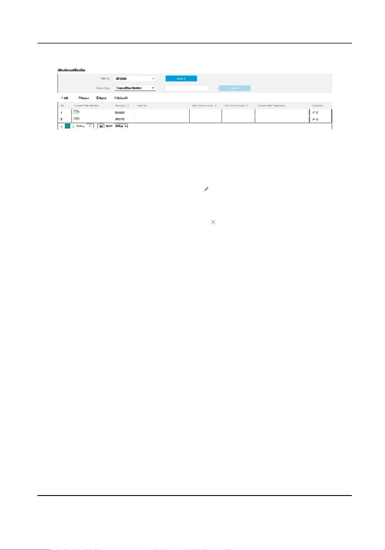
Figure 3-10 Set Allowlist and Blocklist
3.
You can search, modify, delete, import, or export the allowlist and blocklist.
Search Select the search type, or enter the keywords. Click Search. The searched vehicle
informaon will be listed below.
Modify Select an item from the list, and click . Modify the informaon, and click OK.
Delete
●
Select the delete type, or enter the keywords. Click Delete to delete the lists of
the same type.
●
Select an item from the list, and click to delete the item.
●
Click Delete All to delete all the lists.
Import a. Click Import.
b. Click Download Template, and save the template.
c. Open the template, edit the informaon, and save it.
d. Click Import again.
e. Click Browse to select the edited template.
f. Click Import to import the
informaon to the device.
Export Click Export and select the saving path to export the allowlist or blocklist to the
computer.
3.12.2 Control Barrier Gate
Link the barrier gate to realize the control and management of the vehicles at the entrance or exit.
Steps
1.
Go to Conguraon → Capture → Entrance and Exit → Barrier Gate .
Smart Monitoring Camera User Manual
35
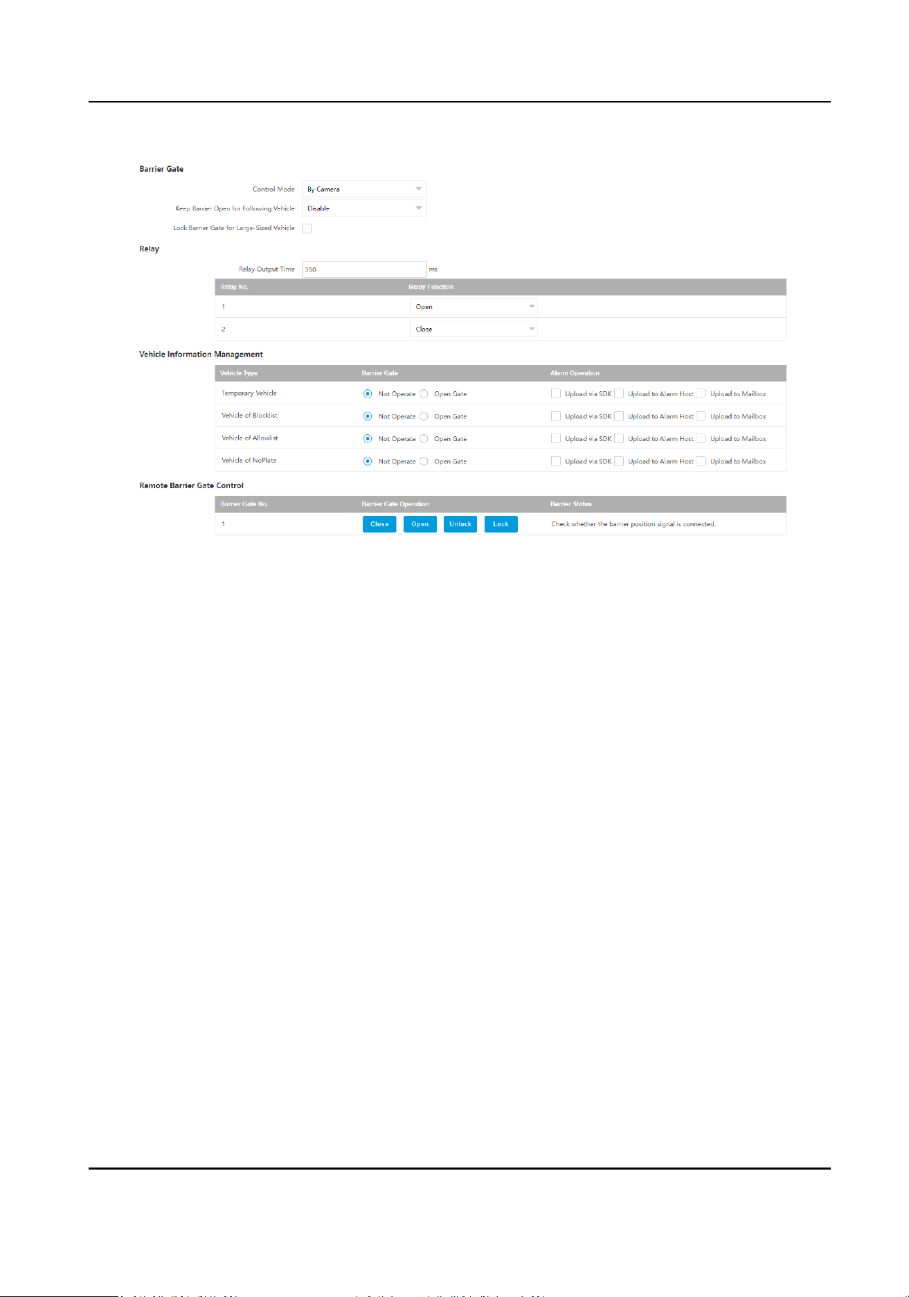
Figure 3-11 Control Barrier Gate
2.
Set Barrier Gate parameters.
Control Mode
●
Select By Camera in single camera scene (no control soware) and allowlist scene in which
the camera controls the barrier gate in advance according to the set passing rules in
Vehicle
Informaon Management.
●
Select By
Plaorm in the scene in which the entry permissions are controlled by the
soware.
●
Select By Mixed, and the
plaorm control and camera control are eecve simultaneously.
It is applicable to the scene in which dierent vehicle passing permissions are managed by
soware and camera. E.g., the soware controls the passing of blocklist vehicles and
temporary vehicles, and the camera controls the passing of allowlist vehicles and controls
the barrier gate in advance for allowlist vehicles.
Keep Barrier Open for Following Vehicle
Aer you enable this funcon, the barrier gate keeps open when the device detects following
vehicles are passing. The barrier gate will close aer the following vehicles pass.
Lock Barrier Gate for Large-Sized Vehicle
Enable the funcon and set Barrier Gate Rising Time. If a large-sized vehicle is passing, the
barrier gate will be locked during the set me.
3.
Set the relay funcon.
Smart Monitoring Camera User Manual
36
Note
The supported number of relays varies with dierent models. Relay 1 corresponds to the 1A and
1B of the terminal. Relay 2 corresponds to the 2A and 2B of the terminal.
4.
Set the barrier gate operaon and alarm operaon for the temporary vehicles, vehicles of the
blocklist, vehicles of the allowlist, and vehicles without license plates.
-
Check Upload via SDK to arm and upload the vehicle informaon to the arming terminal via
SDK.
-
If the device has been connected to the alarm device, check Upload to Alarm Host. When the
barrier gate is open, the alarm device will be triggered to alarm.
-
Check Upload to Mailbox to email the vehicle informaon to the user.
5.
Oponal: You can click Close, Open, Unlock, or Lock to control the barrier gate remotely.
Note
The funcons of remote control of barrier gate vary with dierent models. The actual device
prevails.
6.
Click Save.
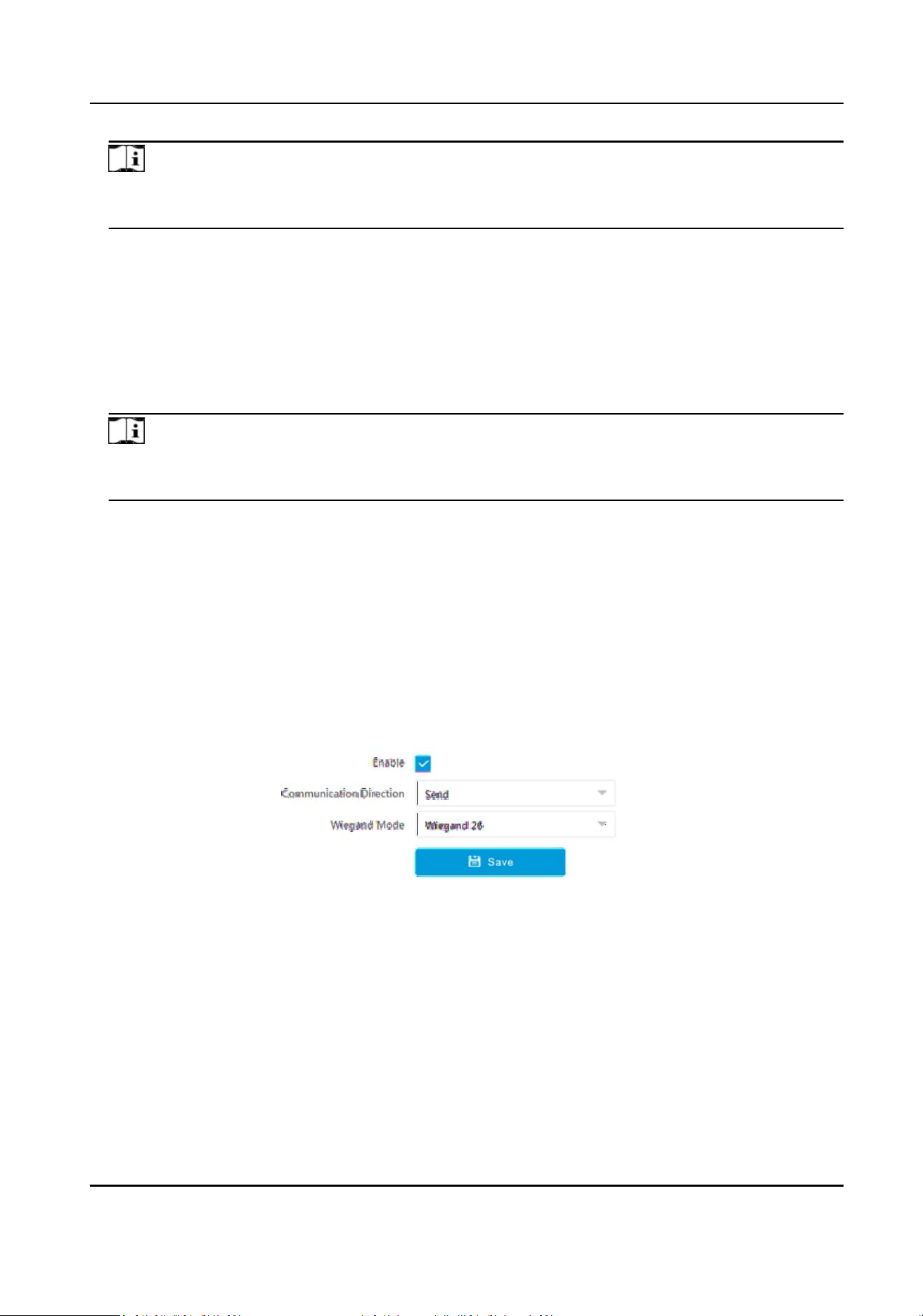
3.12.3 Set Wiegand Parameters
The device can get access to the access control system or other system supporng Wiegand
protocols to send data in the entrance and exit scenes.
Steps
1.
Go to Conguraon → Capture → Entrance and Exit → Wiegand Parameters .
2.
Check Enable.
Figure 3-12 Set Wiegand Parameters
3.
Select Communicaon Direcon.
Send
The barrier gate can be connected to the device via Wiegand 26 or Wiegand 34 mode.
4.
Select Wiegand Mode.
Wiegand 26
It is applicable to all the access control projects. The device will get the card No. (pure
numbers with no more than 8 digits) from the allowlist and blocklist related to the captured
Smart Monitoring Camera User Manual
37

license plate number and send the card No. to the access control system or other system
supporng Wiegand protocols via Wiegand 26 protocol.
Wiegand 34
It is applicable to all the access control projects. The device will get the card No. (pure
numbers with no more than 10 digits) from the allowlist and blocklist related to the captured
license plate number and send the card No. to the access control system or other system
supporng Wiegand protocols via Wiegand 34 protocol.
5.
Click Save.
Smart Monitoring Camera User Manual
38
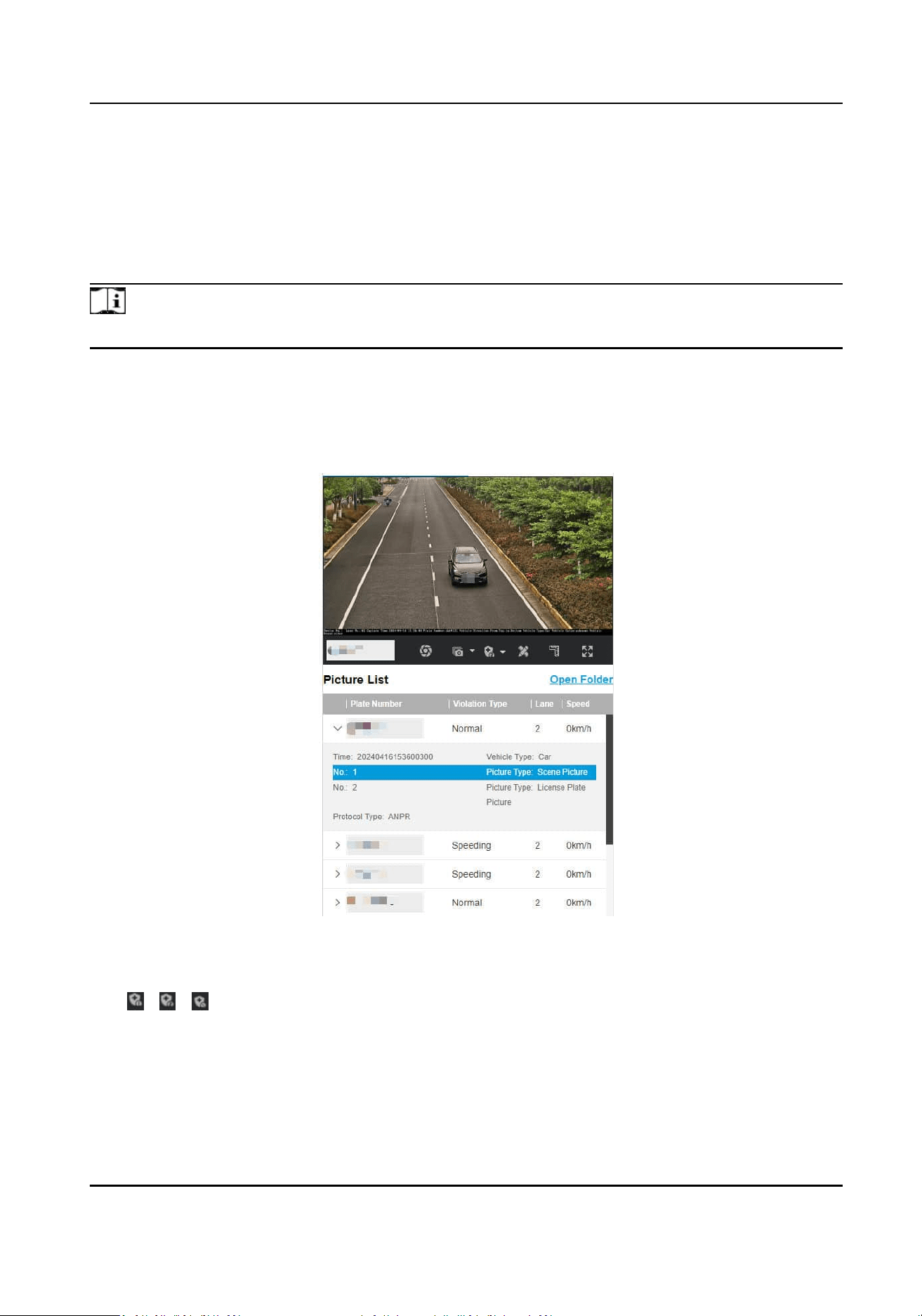
Chapter 4 View Real-Time Picture
You can view the real-me captured pictures and license plate informaon.
Steps
Note
The supported parameters vary with dierent models. The actual device prevails.
1.
Go to Live View → Real-Time Capture .
2.
Click Arming.
3.
Select an item from the list, and you can view the capture scene picture and recognized license
plate
informaon.
Figure 4-1 Real-Time Capture
4.
Oponal: You can also do the following operaons.
/
/
●
Level 1 Arming can only connect one client or web. The uploaded pictures will
not be stored in the storage card. The pictures in the storage card will be
uploaded to the level 1 arming.
●
Level 2 Arming can connect three clients or webs. The pictures will be
uploaded to the client/web, and stored in the storage card.
●
Disarming is to cancel the alarm status or real-me picture.
Smart Monitoring Camera User Manual
39

Click it to measure the license plate pixel. Click it again to disable the
measurement.
Click it to enable the ruler to measure the license plate.
Click it to enable manual capture.
Click it to set connuous capture parameters and the device will capture
pictures according to the set interval.
●
Capture Times: Up to ve pictures can be captured per connuous capture.
●
Interval: Up to four intervals can be set, and the default interval is 100 ms.
Display the images in full screen mode.
Open
Folder
Open the saving path of captured pictures.
Smart Monitoring Camera User Manual
40
Chapter 5 View Trac Stascs
5.1 View Real-Time Trac Stascs
You can view the real-me trac stascs if the device supports this funcon.
Steps
Note
This funcon varies with dierent models. The actual device prevails.
1.
Go to Conguraon → Capture → Advanced → Trac Parameters → Trac Parameters .
2.
Check Enable.
3.
Set Interval.
4.
Go to Live View →
Trac Stascs to view real-me data.
5.2 View
Trac Flow Stascs
The device supports counng and uploading trac follow data.
Steps
Note
This funcon varies with dierent models. The actual device prevails.
1.
Go to Conguraon → Capture → Advanced → Trac Parameters → TPS Parameters .
2.
Check Enable.
3.
Set Interval.
4.
Click Save.
Smart Monitoring Camera User Manual
41
Chapter 6 Live View and Local Conguraon
6.1 Live View
6.1.1 Start/Stop Live View
Click to start live view. Click to stop live view.
6.1.2 Select Image Display Mode
Click to select an image display mode.
6.1.3 Select Window Division Mode
Click to select a window division mode.
6.1.4 Select Stream Type
Click to select the stream type. It is recommended to select the main stream to get the high-
quality image when the network condion is good, and select the sub-stream to get the uent
image when the network condion is not good enough. The third stream is custom.
Note
The third stream varies with dierent models. The actual device prevails.
6.1.5 Capture Picture Manually
You can capture pictures manually on the live view image and save them to the computer.
Steps
1.
Click to capture a picture.
2.
Oponal: Click Conguraon → Local → Live View Parameters and select Image Format.
3.
Oponal: Click Conguraon → Local → Picture and Clip Sengs to view the saving path of
snapshots in live view.
6.1.6 Record Manually
You can record videos manually on the live view image and save them to the computer.
Smart Monitoring Camera User Manual
42
Steps
1.
Click to start live view.
2.
Click to start recording.
3.
Click
to stop recording.
4.
Oponal: Click Conguraon → Local → Record File Sengs to view the saving path of record
les.
6.1.7 Start/Stop Two-Way Audio
The device supports two-way audio with terminals, such as computers.
Before You Start
The device is equipped with an audio input interface and audio output interface, which support
connecng with the corresponding devices, such as microphones and loudspeakers.
Steps
Note
The funcon varies with dierent models. The actual device prevails.
1.
Select a window to start two-way audio.
2.
Click to start live view.
3.
Click
to start two-way audio.
When speaking at the PC end, you can hear the voice at the device end and vice versa.
4.
Click
to stop two-way audio.
6.1.8 Enable/Disable Audio
Enable the audio if necessary aer connecng an audio input device under the audio & video
stream. Click
to enable and adjust it. Click again to disable this funcon.
Note
The funcon varies with dierent models. The actual device prevails.
6.1.9 Enable Digital Zoom
You can enable digital zoom to zoom in a certain part of the live view image.
Steps
1.
Click to start live view.
2.
Click
to enable digital zoom.
3.
Place the cursor on the live view image posion which needs to be zoomed in. Drag the mouse
rightwards and downwards to draw an area.
Smart Monitoring Camera User Manual
43
The area will be zoomed in.
4.
Click any posion of the image to restore to normal image.
5.
Click to disable digital zoom.
6.1.10 Enable Regional Focus
Steps
Note
The funcon varies with dierent models. The actual device prevails.
1.
Click .
2.
Drag the cursor from the upper
le corner to the lower right corner to select the area that needs
to be focused.
Result
The selected area is focused.
6.1.11 Select Video Mode
Set the video mode when adjusng the device focus during construcon.
Click and select when the device is running normally.
6.2 PTZ
Operaon
Click Live View. Click and click to show the PTZ control panel.
Note
●
The PTZ supports power-o memory. When the device is suddenly cut o power or restarted
normally, it can automacally return to the posion before the power cut or reboot.
●
The PTZ funcon varies with dierent models. The actual device prevails.
●
Other
unmenoned buons are reserved buons.
Smart Monitoring Camera User Manual
44
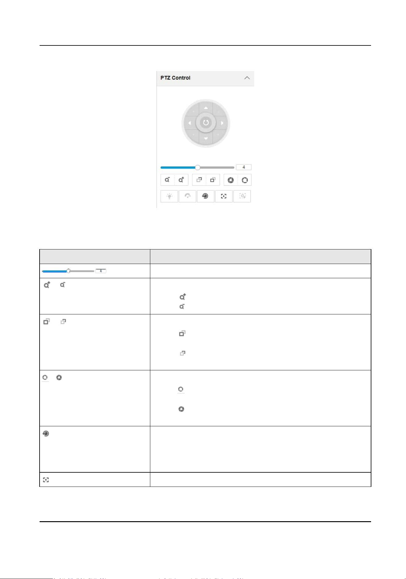
Figure 6-1 PTZ Control Panel
Table 6-1 Buon Descripon
Buon Descripon
Adjust the PTZ speed.
/ Zoom + and Zoom -
●
Hold to zoom in the scene.
●
Hold to zoom out the scene.
/ Focus + and Focus -
●
Hold under the manual focus mode to make near objects
become clear and distant objects become vague.
●
Hold
to make distant objects become clear and near
objects become vague.
/ Iris + and Iris –
●
Hold to increase the iris diameter when in a dark
environment.
●
Hold
to decrease the iris diameter when in a bright
environment.
Lens Inializaon
It is applicable to devices with motorized lenses. You can use this
funcon when overcoming image blurs caused by overme
zooming or focusing.
Auxiliary Focus
Smart Monitoring Camera User Manual
45
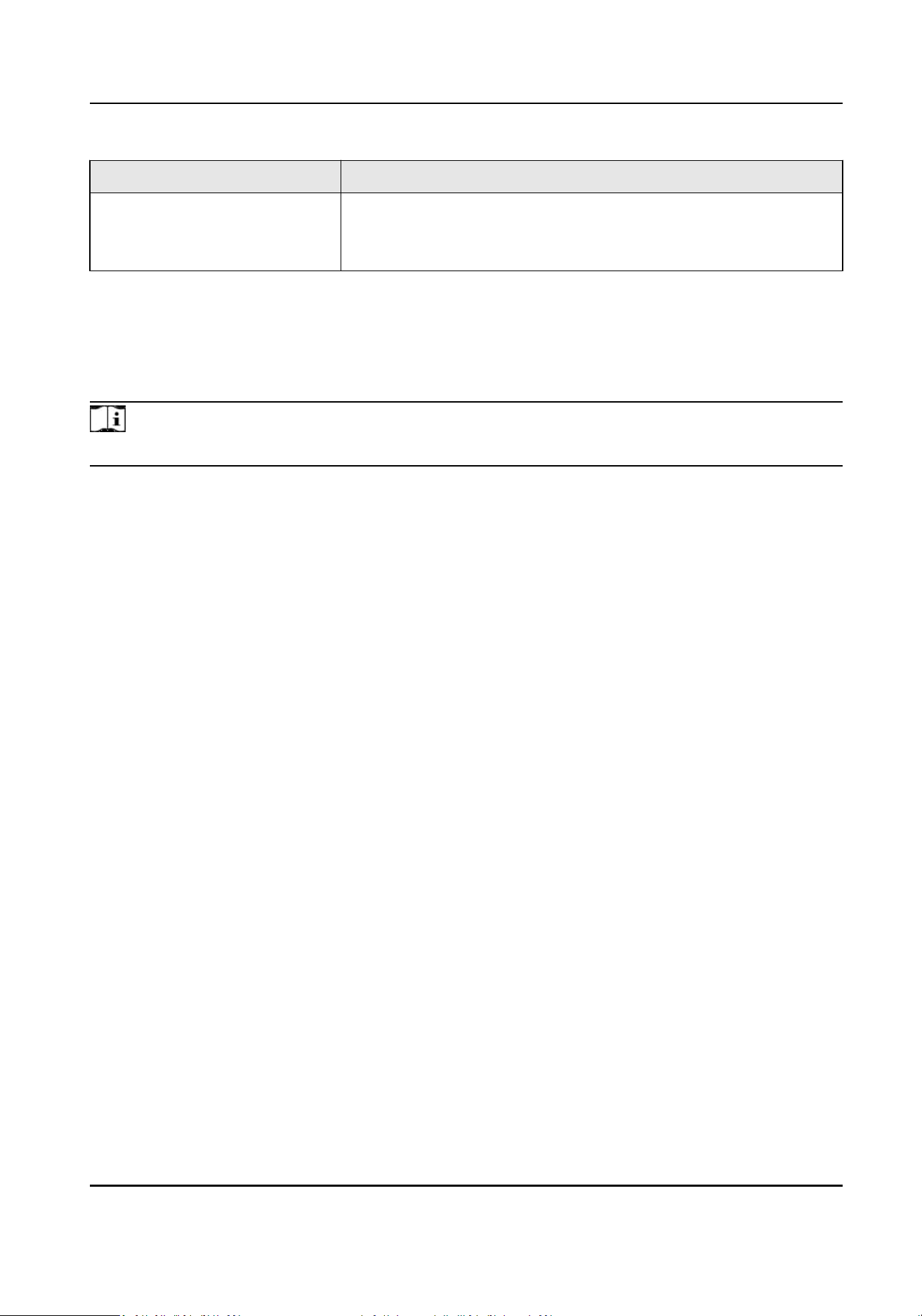
Buon Descripon
It is applicable to devices with motorized lenses. Use this
funcon to focus the lens automacally and make images
become clear.
6.3 Local Conguraon
Go to Conguraon → Local to set the live view parameters and change the saving paths of videos,
captured pictures, scene pictures, etc.
Note
The parameters vary with dierent models. The actual device prevails.
Smart Monitoring Camera User Manual
46
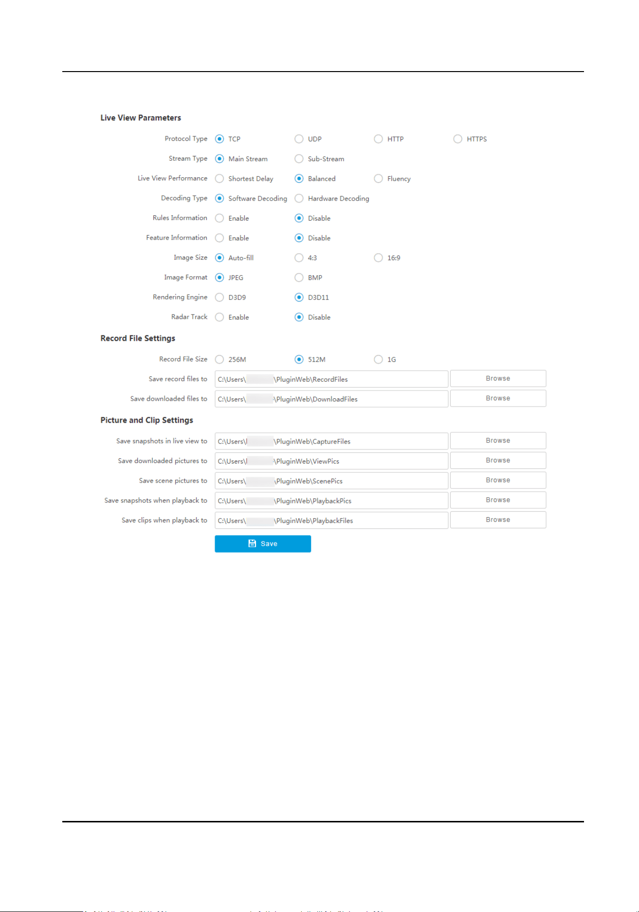
Figure 6-2 Local Conguraon
Protocol Type
Select the network transmission protocol according to the actual needs.
TCP
Ensures complete delivery of streaming data and
beer video quality, but the real-me
transmission will be aected.
UDP
Provides real-me audio and video streams.
HTTP
Gets streams from the device by a third party client.
Smart Monitoring Camera User Manual
47

HTTPS
Gets streams in hps format.
Stream Type
Main Stream
Select it to get the high-quality image when the network
condion is good.
Sub-Stream
Select it to get the uent image when the network condion is not good enough.
Live View Performance
Shortest Delay
The video is real-me, but its uency may be aected.
Balanced
Balanced mode considers both the real me and uency of the video.
Fluency
When the network condion is good, the video is uent.
Decoding Type
Soware Decoding
Decode via soware. It takes up more CPU resources but provides images with beer quality
when it compares to the hardware decoding.
Hardware Decoding
Decode via GPU. It takes up less CPU resources but provides images with worse quality when
it compares to the
soware decoding.
Rules Informaon
If you enable this funcon, tracking frames will be displayed on the live view interface when
there are vehicles passing.
Feature Informaon
Enable it to display feature informaon of the target on the live view image.
Image Size
The display rao of the live view image.
Image Format
The saving format of manually captured images.
Rendering Engine
Select the rendering API of the browser. D3D9 uses xed rendering pipeline. D3D11 uses
programmable graphics pipeline, in which the shader replaces the tradional xed rendering
pipeline to improve visual
eects and enhance the picture quality.
Radar Track
Smart Monitoring Camera User Manual
48

When the radar is connected, enable it to generate and overlay the radar tracks.
Record File Size
Select the packed size of the manually recorded video les. Aer the selecon, the max. record
le size is the value you selected.
Save record
les to
Set the saving path of the manually recorded video les.
Save downloaded les to
Set the saving path of the download les.
Save snapshots in live view to
Set the saving path of the manually captured pictures in live view mode.
Save downloaded pictures to
Set the saving path of the downloaded pictures.
Save scene picture to
Set the saving path of the captured pictures in Live View → Real-Time Capture .
Save snapshots when playback to
Set the saving path of the manually captured pictures in playback mode.
Save clips when playback to
Set the saving path of the clips in playback mode.
Smart Monitoring Camera User Manual
49
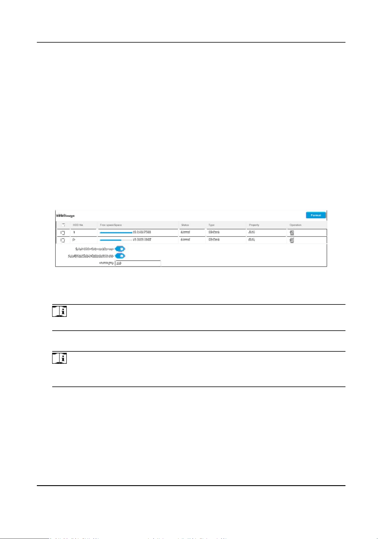
Chapter 7 Record and Capture
7.1 Set Storage Path
7.1.1 Set Storage Card
If you want to store the les to the storage card, make sure you insert and format the storage card
in advance.
Before You Start
Insert the storage card to the device.
Steps
1.
Go to
Conguraon → Storage → Storage Management → HDD Management → HDD Storage .
Figure 7-1 Set Storage Card
2.
Format the storage card in two ways.
-
Check the storage card, and click Format to format it manually.
Note
For the newly installed storage card, you need to format it manually before using it normally.
-
If you want to format the storage card automacally when the card is abnormal, enable Auto-
Inialize Redundant Storage.
Note
If you enable Auto-Inialize Redundant Storage, reboot the device to take the sengs into
eect.
3.
Oponal: If the device has been connected to the plaorm, and you want to upload the storage
card informaon automacally, enable Auto-Upload Data in Redundant Storage and set the
interval.
4.
Click Save.
Smart Monitoring Camera User Manual
50
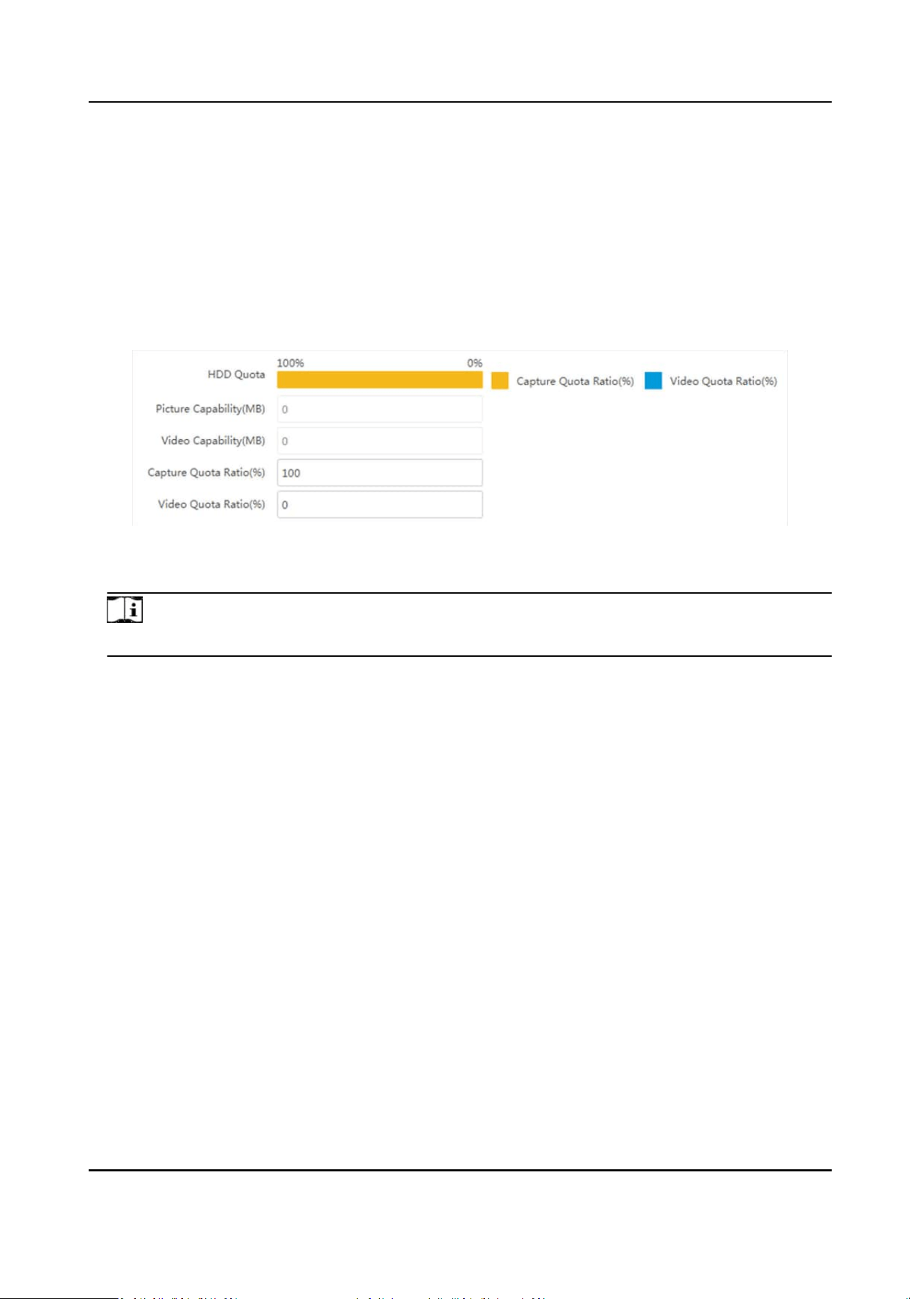
7.1.2 Set Quota
Set the video and picture rao in the storage.
Before You Start
Install the storage card.
Steps
1.
Go to
Conguraon → Storage → Storage Management → HDD Management → HDD Quota .
Figure 7-2 Set Quota
2.
Set Capture Quota Rao and Video Quota Rao according to the actual needs.
Note
The percentage sum of the capture and video quota rao should be 100 %.
3.
Click Save.
What to do next
Format the storage card aer the sengs.
7.1.3 Set FTP
Set FTP parameters if you want to upload the captured pictures to the FTP server.
Before You Start
Set the FTP server, and ensure the device can communicate normally with the server.
Steps
1.
Go to Conguraon → Network → Data Connecon → FTP .
Smart Monitoring Camera User Manual
51
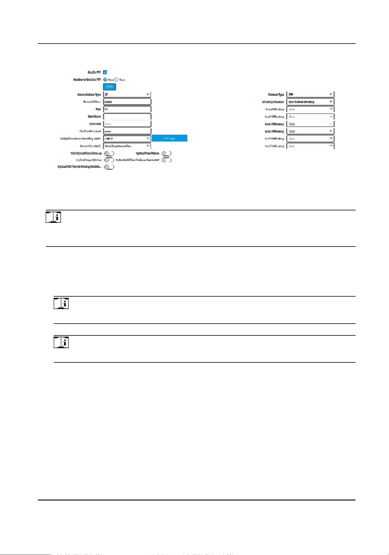
Figure 7-3 Set FTP
2.
Check Enable FTP.
3.
Select Number of Enabled FTP.
Note
You can only enable one FTP if the device does not support the violaon capture. If more than
one FTP is enabled, you should set upload data type for each FTP according to your needs.
4.
Set FTP parameters.
1) Select Sever Address Type and enter corresponding informaon.
2) Enter Port.
3) Enter User Name and Password, and conrm the password.
4) Select Protocol Type.
Note
If you select SFTP, the les will be transmied via encrypon mode to guarantee security.
5) Select Directory Structure.
Note
You can customize the directory structure according to your needs.
6) Select Path/Picture Name Encoding Mode.
UTF-8
UNICODE encoding.
7) Select
Connecon Mode.
Transitory Connecon
The connecon is temporarily made for one data transmission task. Aer this task, the
connecon will be broken.
Persistent Connecon
The connecon is made for long-term data transmission, which will be broken only when
the device is disconnected from the FTP server.
Smart Monitoring Camera User Manual
52
5.
Oponal: Enable upload funcons.
Note
Supported funcons vary with dierent models. The actual device prevails.
Not Upload Plate Close-up
The close-up pictures of a license plate will not be uploaded.
Upload Face Picture
Upload face close-up pictures to the FTP server.
Upload Target Picture
Upload the pictures of the target detecon area to the FTP server.
Upload Addional Informaon to FTP
Add related informaon when uploading data to the FTP server.
Upload CSV Vehicle Passing Stascs Informaon to FTP
Upload the CSV vehicle passing stascs informaon to the FTP server.
6.
Oponal: Click FTP Test to check the FTP server.
7.
Set naming rules and separators according to the actual needs.
Note
For the European version, select Custom and enter adr or ADR in the text eld, and the ADR
(Autorisaon Dangerous Road) vehicle plate number will be added in the corresponding vehicle
picture name.
8.
Oponal: Edit OSD Informaon which can be uploaded to the FTP server with the pictures to
make it convenient to view and
disnguish the data.
9.
Click Save.
7.1.4 Set Cloud Storage
Cloud storage is a kind of network storage. It can be used as the extended storage to save the
captured pictures.
Before You Start
●
Arrange the cloud storage server.
●
You have enabled level 1 arming in Live View → Real-Time Capture .
Note
The real-me capture should be used with dedicated plaorm.
Steps
1.
Go to Conguraon → Storage → Storage Management → Cloud Storage .
Smart Monitoring Camera User Manual
53
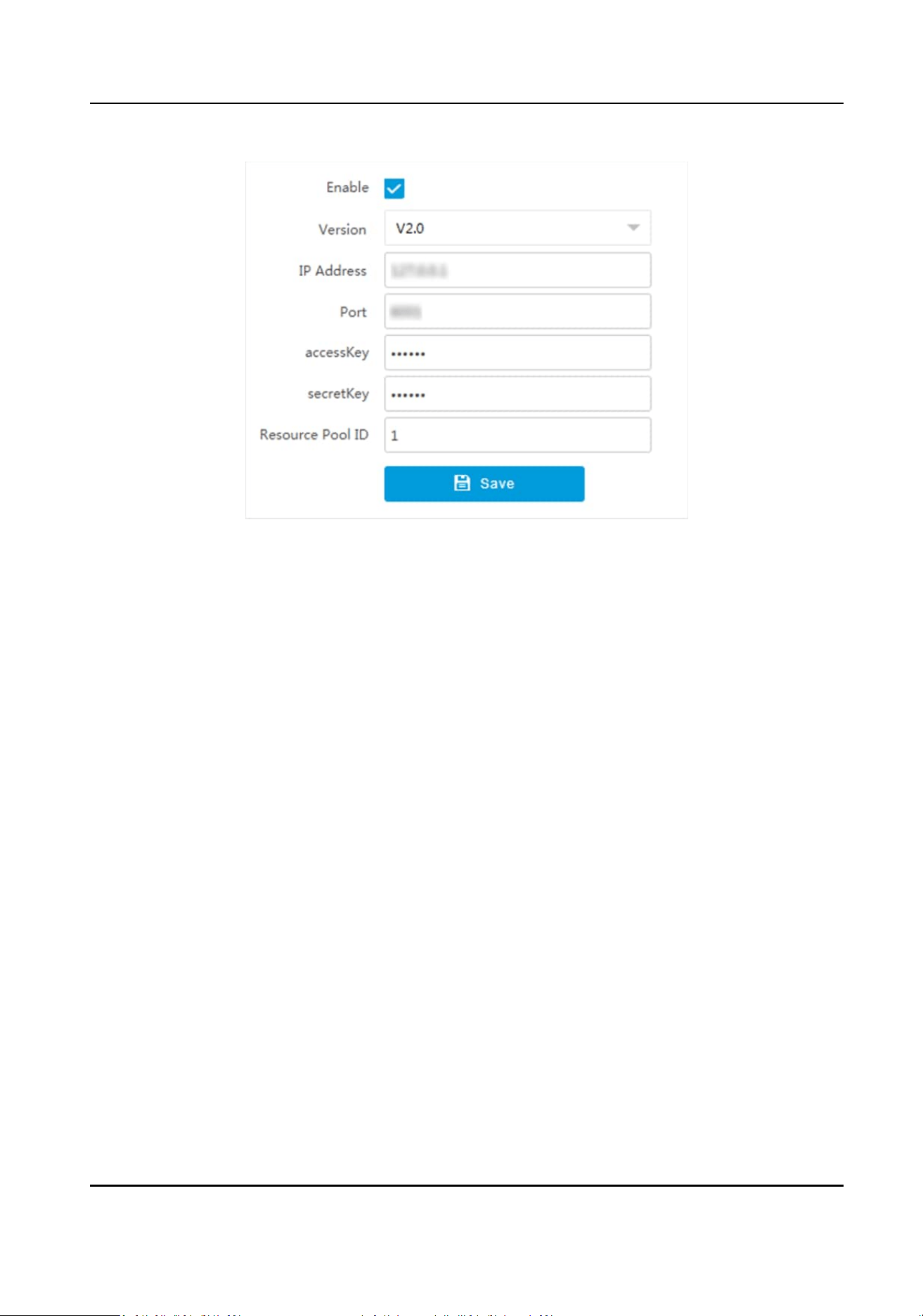
Figure 7-4 Set Cloud Storage
2.
Check Enable.
3.
Select Version.
V1.0
a. Enter IP Address and Port
b. Enter User Name and Password.
c. Enter Cloud Storage ID and Violaon Cloud Storage ID according to the server
storage area No.
V2.0 a. Enter IP Address and Port
b. Enter accessKey and secretKey.
c. Enter Resource Pool ID according to the server storage area No. of uploading
pictures.
4.
Click Save.
7.2 Set Record Schedule
Set record schedule to record video automacally during congured me periods.
Before You Start
Install the storage card.
Steps
1.
Go to Conguraon → Storage → Schedule Sengs → Record Schedule .
2.
Oponal: Enable the funcons below according to your needs.
Enable Recording
Overwring
Smart Monitoring Camera User Manual
54
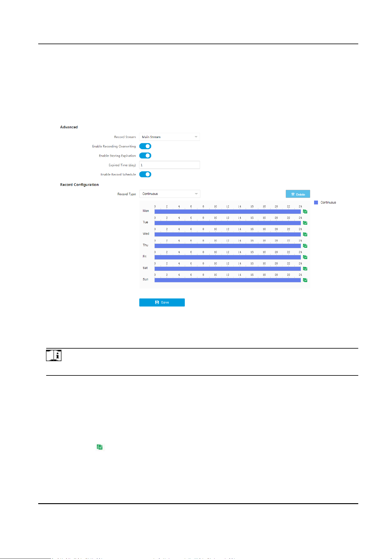
When the storage is full, the earliest videos will be overwrien.
Enable Storing Expiraon
Enable the funcon and set Expired Time for the recorded videos stored in the storage card.
Beyond the me, the les will be overwrien.
3.
Enable the record schedule.
Figure 7-5 Set Record Schedule
4.
Select Record Type.
5.
Drag the cursor on the me bar to set a recording me.
Note
Up to 8 me periods can be set on a me bar.
6.
Adjust the recording me.
-
Click a set recording period and enter the start me and end me in the pop-up window.
-
Drag two ends of the set recording period bar to adjust the length.
-
Drag the whole set recording period bar and relocate it.
7.
Oponal: Delete recording periods.
-
Click a set recording period and click Delete in the pop-up window.
-
Click a set recording period and click Delete on the record
conguraon interface.
8.
Oponal: Click to copy set recordings to other days.
9.
Click Save.
Smart Monitoring Camera User Manual
55
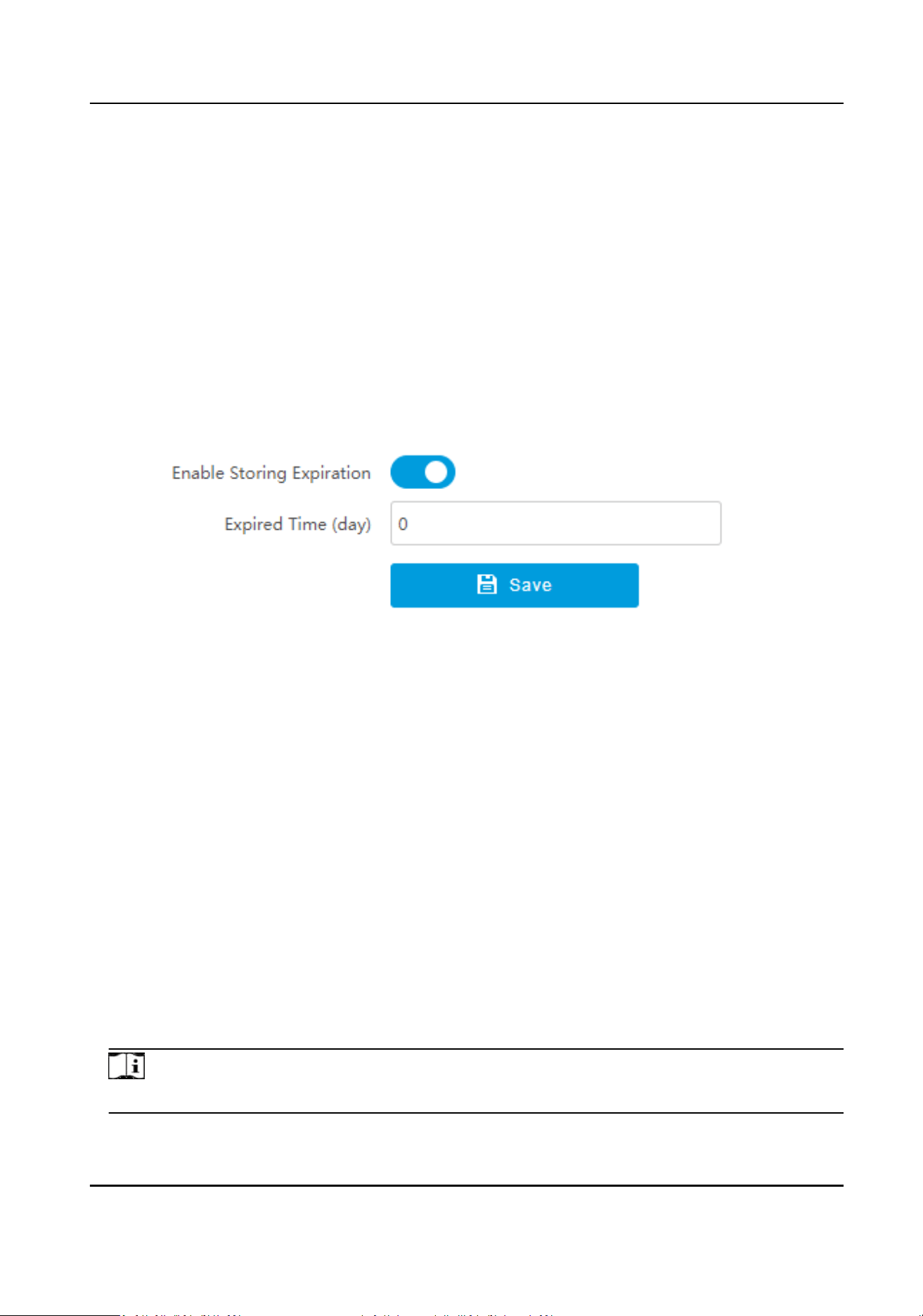
Result
The device will only record at the set periods.
7.3 Set Snapshot Schedule
You can enable storage expiraon of the snapshots saved in the storage card.
Before You Start
Install the storage card.
Steps
1.
Go to
Conguraon → Storage → Schedule Sengs → Snapshot Schedule .
Figure 7-6 Set Snapshot Schedule
2.
Enable storing expiraon.
3.
Set Expired Time.
4.
Click Save.
Result
Beyond the set expired me, the snapshots saved in the storage card will be overwrien.
7.4 Search Picture
You can search the captured pictures stored in the storage card and export the pictures you need.
Before You Start
Install the storage card, and ensure the storage status is normal.
Steps
1.
Click Picture.
2.
Set search
condions.
Note
Search condions vary with dierent models. The actual device prevails.
Smart Monitoring Camera User Manual
56
3.
Click Search.
The searched pictures informaon will be displayed in the picture list.
Note
If you have set level 1 arming for the device, the captured pictures will not be saved in the
storage card. Go to the saving path of scene pictures to view them. You can go to Conguraon
→ Local to check the saving path.
4.
Oponal: Check picture(s) and click Download to save them to local.
The downloaded picture(s) will be marked as "Downloaded". You can go to
Conguraon →
Local to check the saving path.
7.5 Playback
You can search, play back, and download videos that stored on the storage card.
Steps
1.
Click Playback.
2.
Select a channel.
3.
Select a date.
4.
Click Search.
5.
Click
to start playback.
6.
Oponal: You can also do the following operaons.
Set playback
me
●
Drag the me bar to the target me and click to play the video.
●
Click the current me point showed above the me bar and enter
the target me point in the popup window. Click OK and click to
play the video.
Capture image Click to capture an image.
Clip record Click / to start/stop clipping the record.
Play back in single
frame
Click once to play back the video in one frame.
Download record a. Click .
b. Select the start me and end me.
c. Click Search.
d. Check record
les that need to be downloaded.
e. Click Download.
Stop playback Click to stop playback.
Slow forward Click to slow down the playback.
Fast forward Click to speed up the playback.
Digital zoom Click to enable digital zoom.
Smart Monitoring Camera User Manual
57

Click to disable digital zoom.
Adjust volume Click to enable volume.
Smart Monitoring Camera User Manual
58
Chapter 8 Encoding and Display
8.1 Set Video Encoding Parameters
Set video encoding parameters to adjust the live view and recording eect.
●
When the network signal is good and the speed is fast, you can set high resoluon and bitrate to
raise the image quality.
●
When the network signal is bad and the speed is slow, you can set low resoluon, bitrate, and
frame rate to guarantee the image uency.
●
When the network signal is bad, but the resoluon should be guaranteed, you can set low
bitrate and frame rate to guarantee the image uency.
●
Main stream stands for the best stream performance the device supports. It usually oers the
best resoluon and frame rate the device can do. But high resoluon and frame rate usually
means larger storage space and higher bandwidth requirements in transmission. Sub-stream
usually
oers comparavely low resoluon opons, which consumes less bandwidth and storage
space. Third stream is oered for customized usage.
Steps
Note
The supported parameters vary with dierent models. The actual device prevails.
1.
Go to Conguraon → Video → Video Encoding → Video Encoding .
2.
Set the parameters for dierent streams.
Stream Type
Select the stream type according to your needs.
Note
The supported stream types vary with dierent models. The actual device prevails.
Bitrate
Select relavely large bitrate if you need good image quality and eect, but more storage
spaces will be consumed. Select
relavely small bitrate if storage requirement is in priority.
Frame Rate
It is to describe the frequency at which the video stream is updated and it is measured by
frames per second (fps). A higher frame rate is advantageous when there is movement in the
video stream, as it maintains image quality throughout.
Resoluon
The higher the resoluon is, the clearer the image will be. Meanwhile, the network
bandwidth requirement is higher.
Smart Monitoring Camera User Manual
59

SVC
Scalable Video Coding (SVC) is an extension of the H.264/AVC and H.265 standard. Enable the
funcon and the device will automacally extract frames from the original video when the
network bandwidth is insucient.
Bitrate Type
Select the bitrate type to constant or variable.
Video Quality
When bitrate type is variable, 6 levels of video quality are selectable. The higher the video
quality is, the higher requirements of the network bandwidth.
Prole
When you select H.264 or H.265 as video encoding, you can set the prole. Selectable
proles vary according to device models.
I Frame Interval
It refers to the number of frames between two key frames. The larger the I frame interval is,
the smaller the stream uctuaon is, but the image quality is not that good.
Video Encoding
The device supports mulple video encoding types, such as H.264, H.265, and MJPEG.
Supported encoding types for
dierent stream types may dier. H.265 is a new encoding
technology. Compared with H.264, it reduces the transmission bitrate under the same
resoluon, frame rate, and image quality.
3.
Click Save.
8.2 Set Image Parameters
You can adjust the image parameters to get clear image.
Steps
Note
The supported parameters may vary with dierent models. The actual device prevails.
1.
Go to Conguraon → Video → Camera Parameter → Camera Parameter .
Smart Monitoring Camera User Manual
60
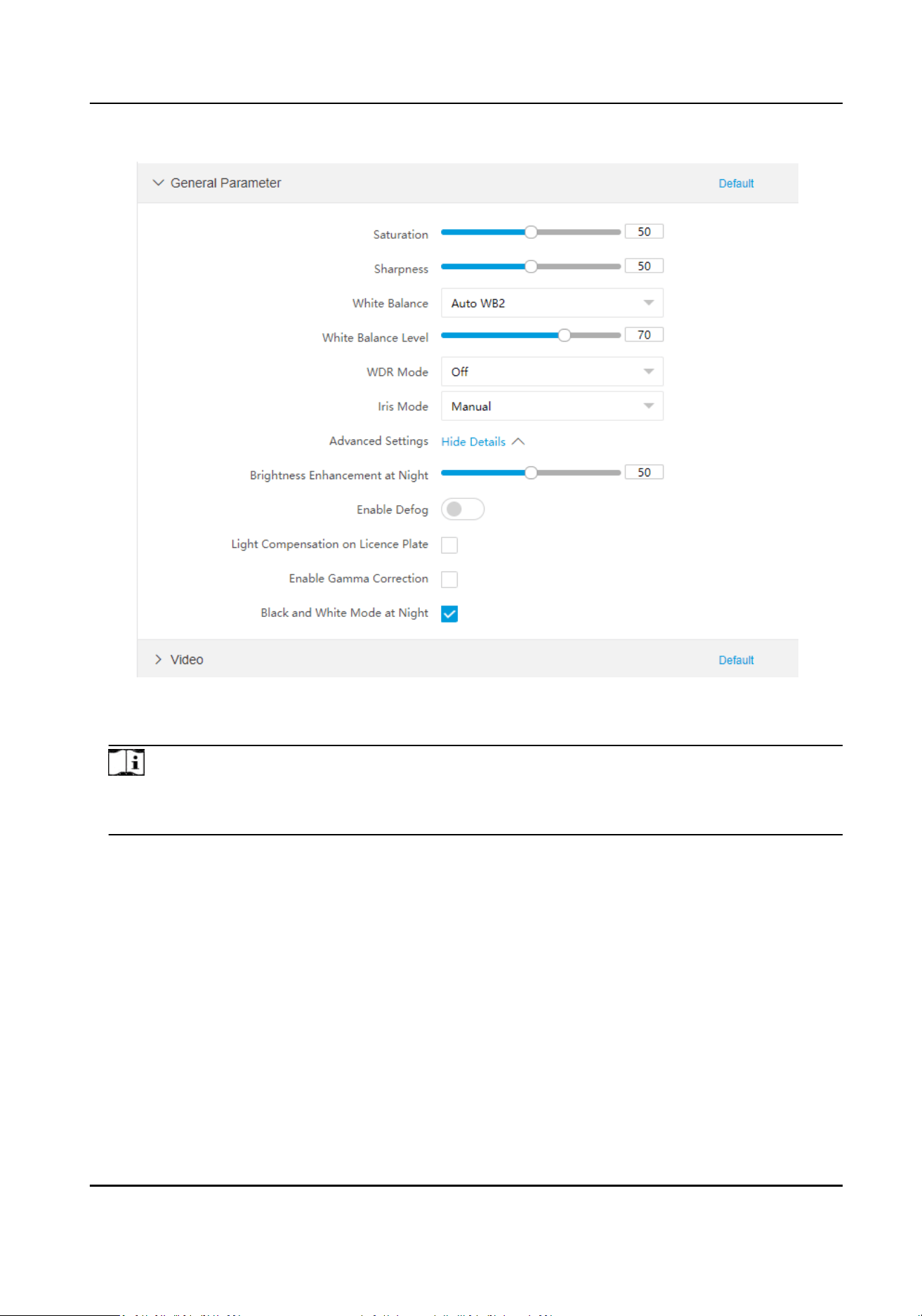
Figure 8-1 Set Image Parameters
2.
Set the camera parameters.
Note
●
The supported parameters vary with dierent models. The actual device prevails.
●
You can click Default to restore the parameters to default sengs.
General Parameter
Saturaon
It refers to the colorfulness of the image color.
Sharpness
It refers to the edge contrast of the image.
White Balance
It is the white rendion funcon of the device used to adjust the color temperature
according to the environment.
WDR Mode
Smart Monitoring Camera User Manual
61

Wide Dynamic Range (WDR) can be used when there is a high contrast of the bright area
and the dark area of the scene.
Select WDR Switch and set corresponding parameters according to your needs.
On
Set WDR Level. The higher the level is, the higher the WDR strength is.
Time
Enable WDR according to the set
me period and level.
Brightness
Set Light Threshold and WDR Level. When the brightness reaches the threshold, WDR
will be enabled.
Iris Mode
Select the iris mode according to your needs.
Brightness Enhancement at Night
The scene brightness will be enhanced at night automacally.
Enable Defog
Enable defog to get a clear image in foggy days.
Light Compensaon on License Plate
Check it. The plate brightness compensaon can be realized, and various light supplement
condions can be adapted via seng license plate expectant brightness and supplement
light
correcon coecient. The higher the sensivity is, the easier this funcon can be
enabled.
Enable Gamma Correcon
The higher the gamma correcon value is, the stronger the correcon strength is.
Black and White Mode at Night
When ICR is in night mode, you can check it to keep the video in black and white mode at
night.
Video
Brightness
It refers to the brightness the image.
Contrast
It refers to the contrast of the image. Set it to adjust the levels and permeability of the
image.
Shuer
If the shuer speed is quick, the details of the moving objects can be displayed beer. If
the shuer speed is slow, the outline of the moving objects will be fuzzy and trailing will
appear.
Smart Monitoring Camera User Manual
62

Gain
It refers to the upper limit value of liming image signal amplicaon. It is recommended
to set a high gain if the illuminaon is not enough, and set a low gain if the illuminaon is
enough.
Hue Range
Select the range to adapt to the display.
3D DNR
Digital Noise
Reducon (DNR) reduces the noise in the video stream.
In Normal Mode, the higher the 3D DNR Level is, the stronger the noise will be reduced.
But if it is too high, the image may become fuzzy.
In Expert Mode, set
Spaal Intensity and Time Intensity. If the space domain intensity is
too high, the outline of the image may become fuzzy and the details may lose. If the
me
domain intensity is too high, trailing may appear.
2D DNR
The higher the 2D DNR Level is, the stronger the noise will be reduced. But if it is too high,
the image may become fuzzy.
Slow Shuer
This funcon can be used in underexposure condion. It lengthens the shuer me to
ensure full exposure. The higher Slow
Shuer Level is, the slower the shuer speed is.
Video Standard
Select the video standard according to the actual power supply frequency.
3.
Oponal: You can click under the live view image to enable digital zoom. Refer to Enable
Digital Zoom for details.
4.
Oponal: Click Capture Test to check the image eect.
8.3 Set ROI
ROI (Region of Interest) encoding helps to assign more encoding resources to the region of
interest, thus to increase the quality of the ROI whereas the background
informaon is less
focused.
Before You Start
Please check the video encoding type. ROI is supported when the video encoding type is H.264 or
H.265.
Steps
1.
Go to
Conguraon → Video → Video Encoding → ROI .
Smart Monitoring Camera User Manual
63
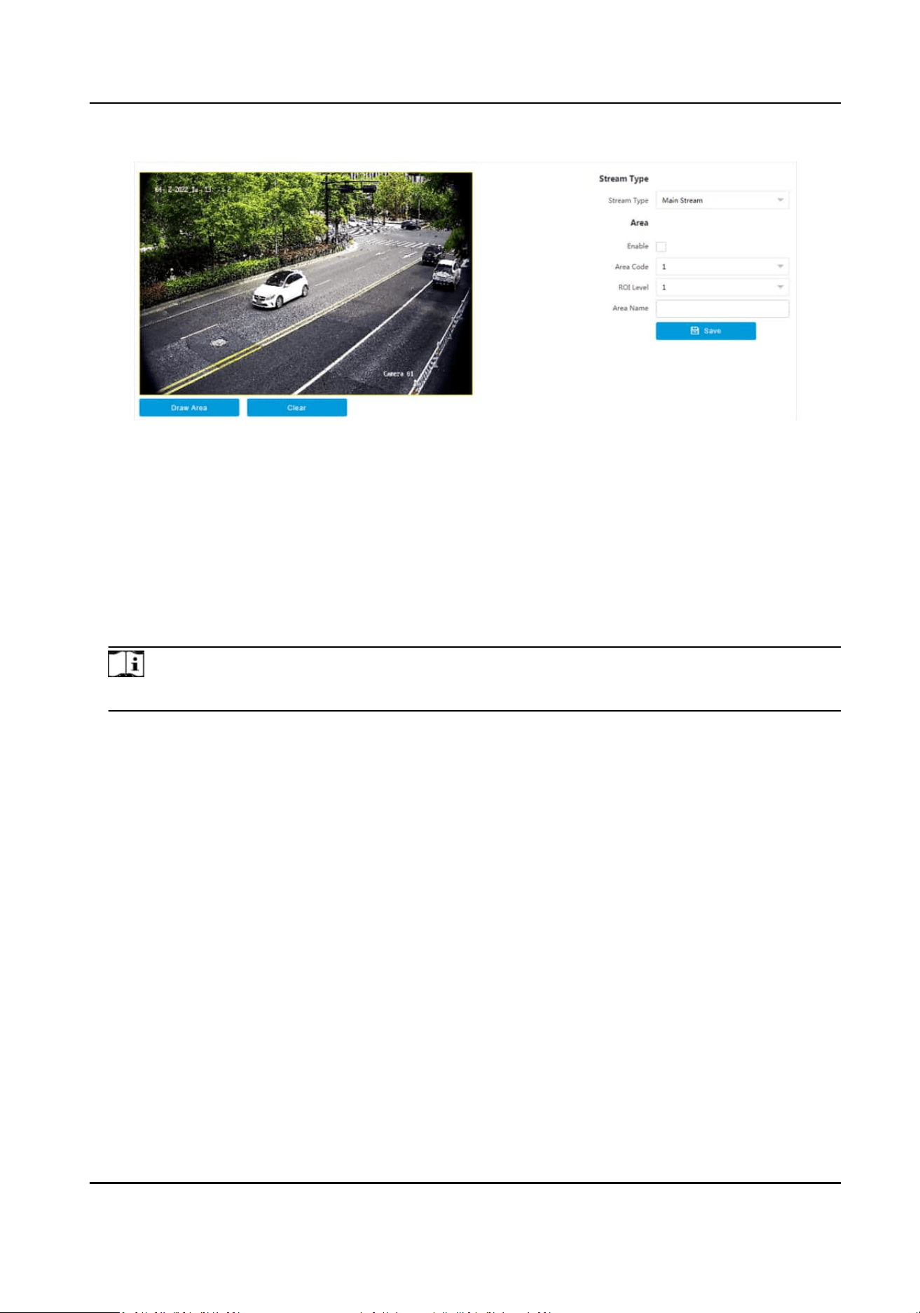
Figure 8-2 Set ROI
2.
Select Stream Type.
3.
Set ROI region.
1) Check Enable.
2) Select Area Code.
3) Click Draw Area.
4) Drag the mouse on the live view image to draw a
xed area.
5) Select the
xed area that needs to be adjusted and drag the mouse to adjust its posion.
4.
Select ROI Level and enter Area Name.
Note
The higher the ROI level is, the clearer the image of the detected area is.
5.
Click Save.
6.
Oponal: Select other area codes and repeat the steps above if you need to draw mulple xed
areas.
8.4 Set Privacy Mask
The privacy mask can be used to protect personal privacy by concealing parts of the image from
view or recording with a masked area.
Steps
1.
Go to
Conguraon → Video → Video Encoding → Privacy Mask .
Smart Monitoring Camera User Manual
64
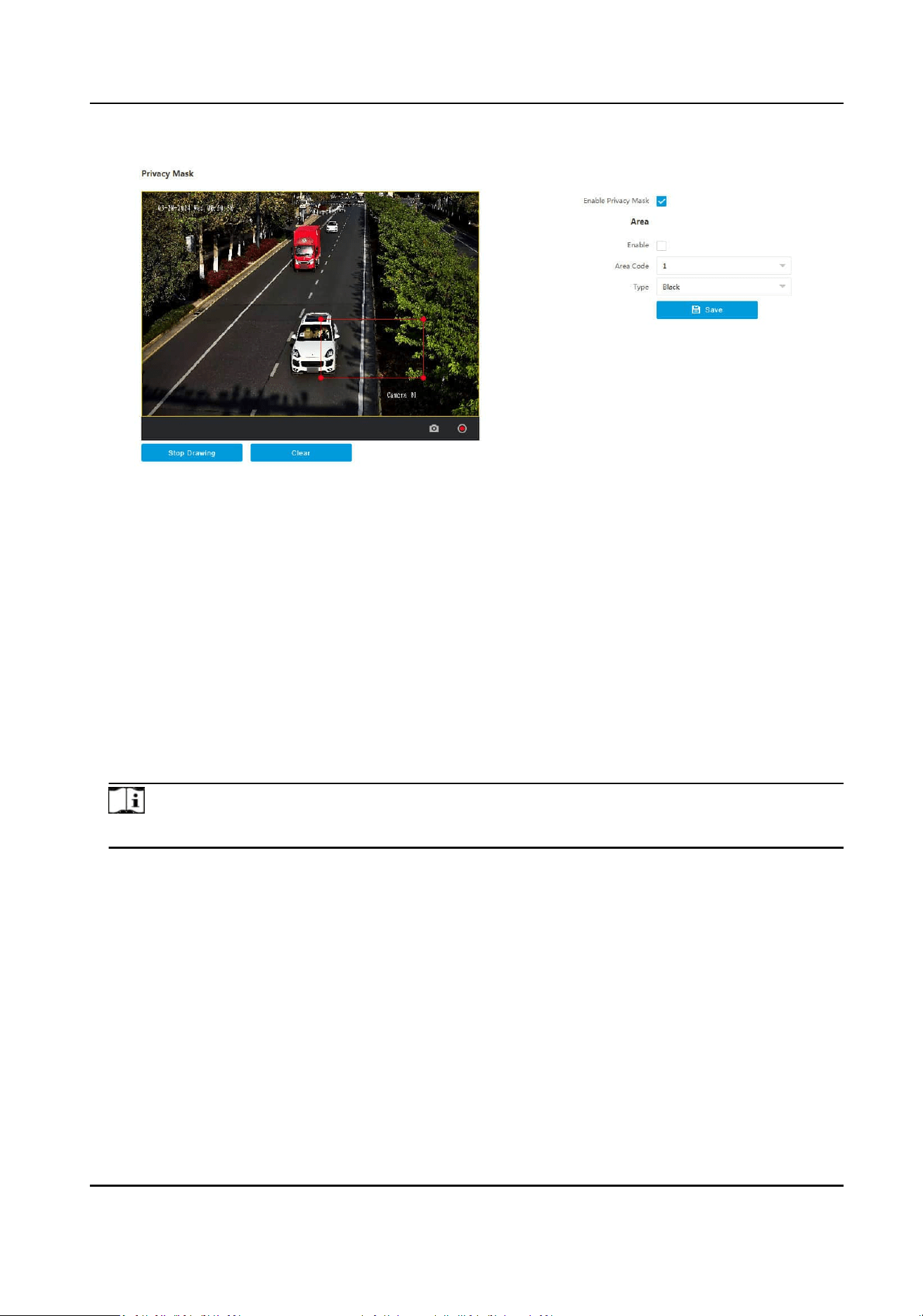
Figure 8-3 Set Privacy Mask
2.
Check Enable Privacy Mask.
3.
Enable the privacy mask area(s).
1) Check Enable.
2) Select Area Code.
3) Select Type.
4.
Draw the privacy mask area.
1) Click Draw Area.
2) In the live view image, drag the mouse to draw the privacy mask area of the selected area
code.
3) Click Stop Drawing.
4)
Oponal: Click Clear to clear all the drawn areas.
5.
Oponal: Repeat step 3 and 4 to draw more privacy mask areas.
Note
Up to four privacy mask areas are supported.
6.
Click Save.
8.5 Enable Regional Exposure
Enable regional exposure to adjust the brightness of the whole live view image according to the
drawn paral area.
Steps
1.
Go to Conguraon → Video → Video Encoding → BLC .
2.
Check Enable.
3.
Drag the mouse to draw an area.
Smart Monitoring Camera User Manual
65
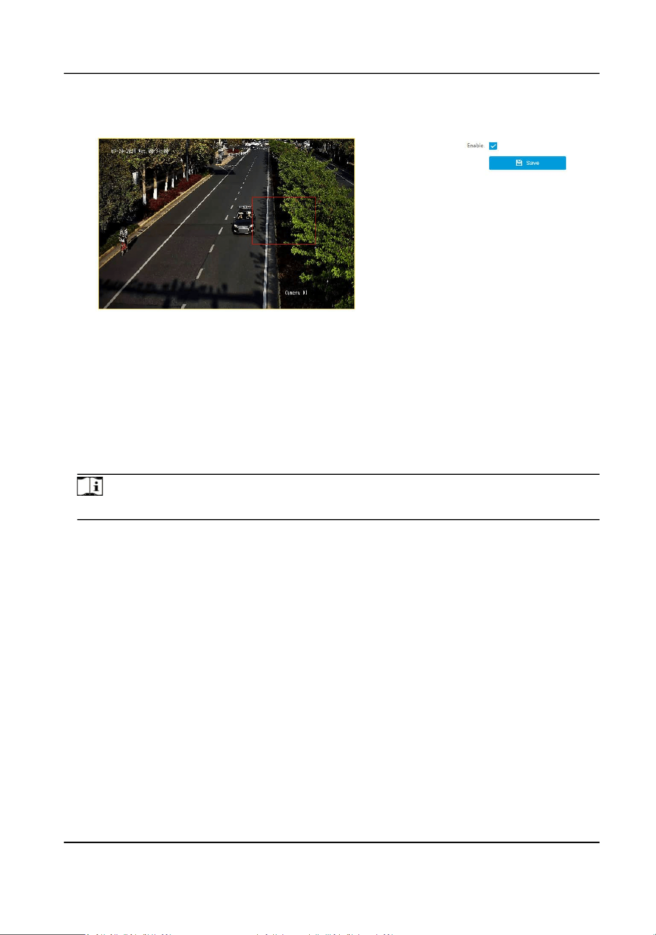
The brightness of the whole live view image will be adjusted according to the drawn area.
Figure 8-4 Enable Regional Exposure
4.
Click Save.
8.6 Set OSD
You can customize OSD informaon on the live view.
Steps
1.
Go to
Conguraon → Video → Text Overlay on Video → Text Overlay on Video .
Note
The supported funcons vary with dierent models. The actual device prevails.
Smart Monitoring Camera User Manual
66
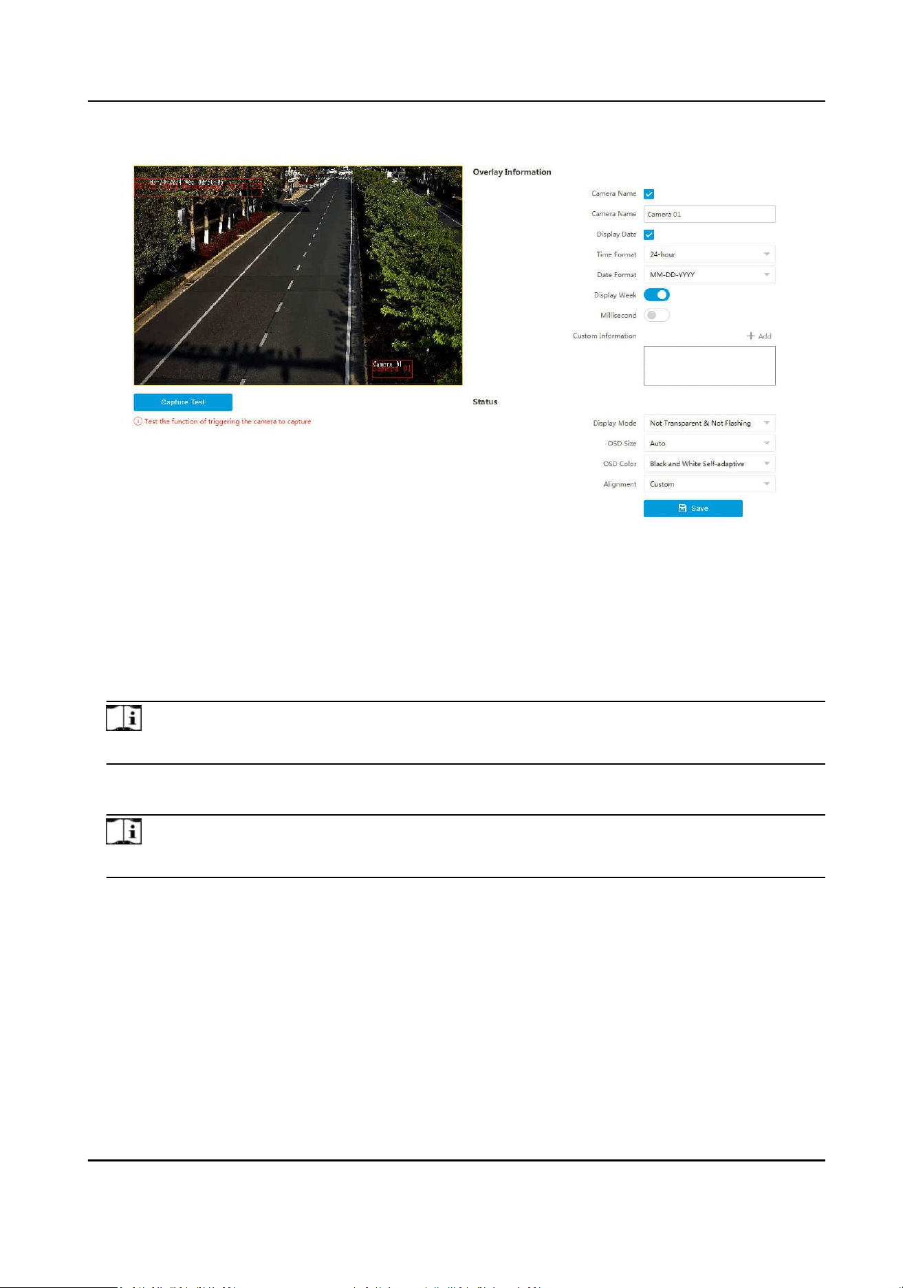
Figure 8-5 Set OSD
2.
Set display contents.
1) Check Camera Name.
2) Enter Camera Name.
3) Check Display Date, and set the
me and date format.
4) Enable Display Week or Millisecond according to your needs.
3.
Oponal: Click Add and enter informaon if you want to add custom informaon.
Note
Up to 6 items of custom informaon can be added.
4.
Set display properes (size, color, etc.).
5.
Select Alignment.
Note
If you select Align Le or Align Right, set Min. Horizontal Margin and Min. Vercal Margin.
6.
Drag the red frames on the live view image to adjust their posions.
7.
Click Save.
Result
The set OSD will be displayed in live view image and recorded videos.
Smart Monitoring Camera User Manual
67

Chapter 9 Network Conguraon
9.1 Set IP Address
IP address must be properly congured before you operate the device over network. IPv4 and IPv6
are both supported. Both versions can be congured simultaneously without conicng to each
other.
Steps
Note
The supported parameters vary with dierent models. The actual device prevails.
1.
Go to Conguraon → Network → Network Parameters → Network Interface .
Smart Monitoring Camera User Manual
68
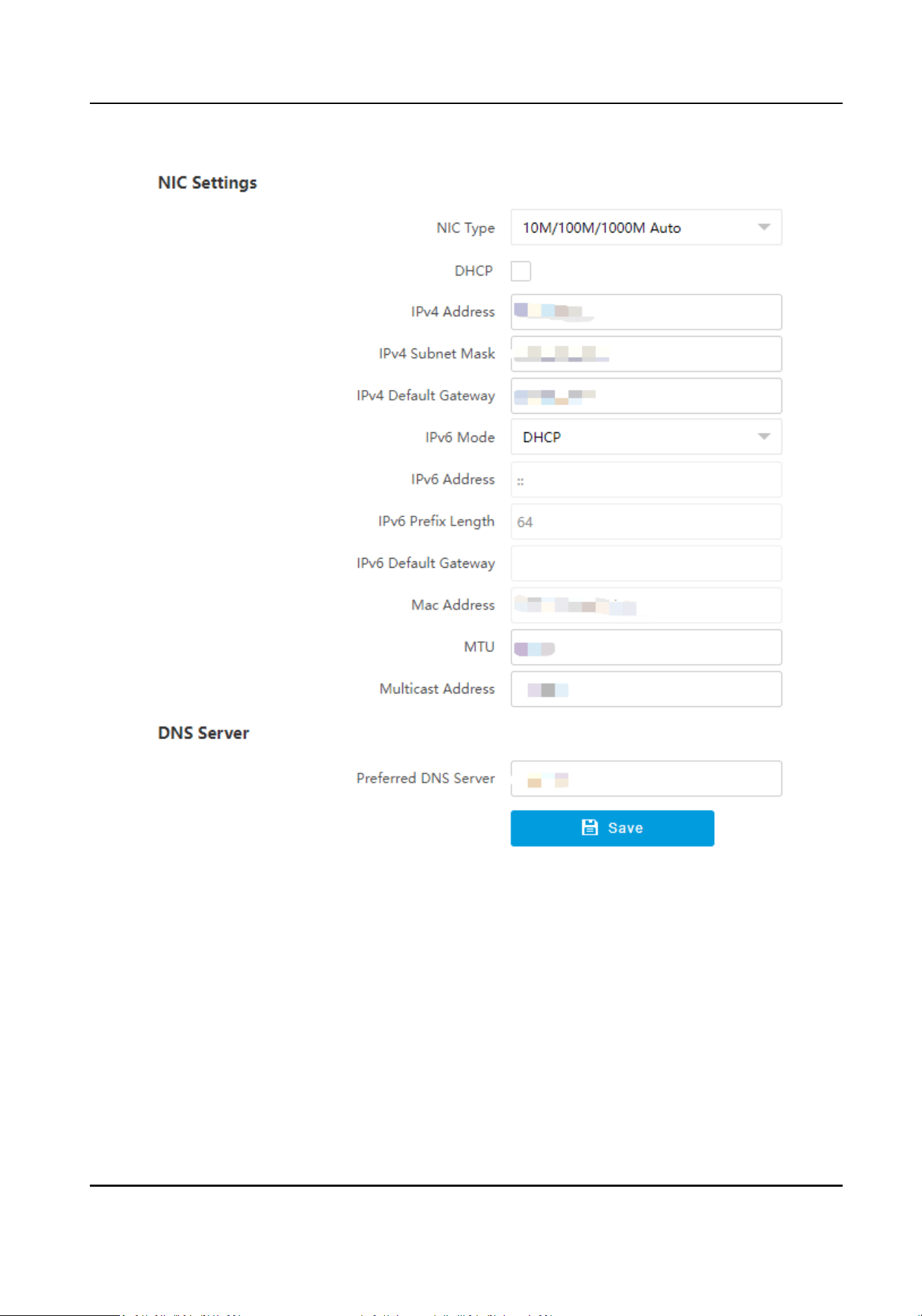
Figure 9-1 Set IP Address
2.
Set network parameters.
NIC Type
Select a NIC (Network Interface Card) type according to your network
condion.
IPv4
Two modes are available.
DHCP
Smart Monitoring Camera User Manual
69
The device automacally gets the IP parameters from the network if you check DHCP. The
device IP address is changed aer enabling the funcon. You can use SADP to get the device
IP address.
Note
The network that the device is connected to should support DHCP (Dynamic Host
Conguraon Protocol).
Manual
You can set the device IP parameters manually. Enter IPv4 Address, IPv4 Subnet Mask, and
IPv4 Default Gateway.
IPv6
Three IPv6 modes are available.
Route
Adversement
The IPv6 address is generated by combining the route adversement and the device Mac
address.
Note
Route adversement mode requires the support from the router that the device is
connected to.
DHCP
The IPv6 address is assigned by the server, router, or gateway.
Manual
Enter IPv6 Address, IPv6 Subnet Mask, and IPv6 Default Gateway. Consult the network
administrator for required
informaon.
MTU
It stands for maximum transmission unit. It is the size of the largest protocol data unit that
can be communicated in a single network layer transacon.
The valid value range of MTU is 1280 to 1500.
Mulcast
Mulcast is group communicaon where data transmission is addressed to a group of
desnaon devices simultaneously. Aer seng the IP address of the mulcast host, you can
send the source data
eciently to mulple receivers.
DNS
It stands for domain name server. It is required if you need to visit the device with domain
name. And it is also required for some applicaons (e.g., sending email). Set Preferred DNS
Address properly if needed.
3.
Click Save.
Smart Monitoring Camera User Manual
70
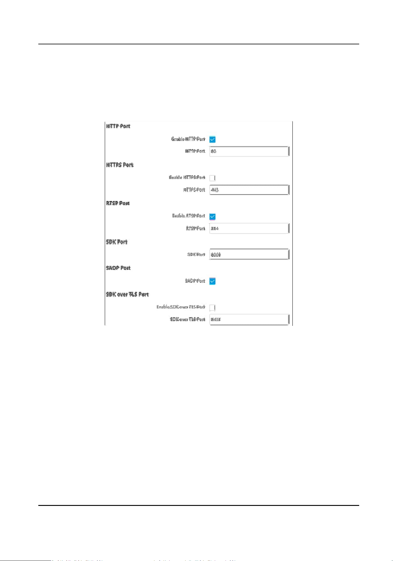
9.2 Set Port
The device port can be modied when the device cannot access the network due to port conicts.
Go to Conguraon → Network → Network Parameters → Port for port sengs.
Figure 9-2 Set Port
HTTP Port
It refers to the port through which the browser accesses the device. For example, when the
HTTP Port is
modied to 81, you need to enter hp://192.168.1.64:81 in the browser for login.
HTTPS Port
It refers to the port through which the browser accesses the device, but cercate vericaon is
needed.
RTSP Port
It refers to the port of
real-me streaming protocol.
SDK Port
It refers to the port through which the client adds the device.
SADP Port
Smart Monitoring Camera User Manual
71
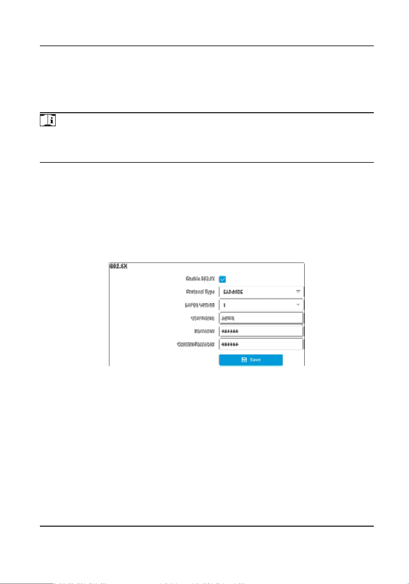
It refers to the port through which the SADP soware searches the device.
SDK over TLS Port
It refers to the port that adopts TLS protocol over the SDK service, to provide safer data
transmission.
Note
●
Aer eding the port, access to the device via the new port.
●
Reboot the device to bring the new sengs into eect.
●
The supported ports vary with dierent models. The actual device prevails.
9.3 Set IEEE 802.1X
IEEE 802.1X is a port-based network access control. It enhances the security level of the LAN/
WLAN. When devices connect to the network with IEEE 802.1X standard, the
authencaon is
needed.
Steps
1.
Go to Conguraon → Network → Network Parameters → 802.1X .
Figure 9-3 Set IEEE 802.1X
2.
Check Enable 802.1X.
3.
Select Protocol Type and EAPOL Version.
Protocol Type
The authencaon server must be congured. Register a user name and password for 802.1X
in the server in advance. Enter the user name and password for
authencaon.
EAPOL Version
The EAPOL version must be idencal with that of the router or the switch.
4.
Enter User Name and Password registered in the server.
5.
Conrm the password.
6.
Click Save.
Smart Monitoring Camera User Manual
72
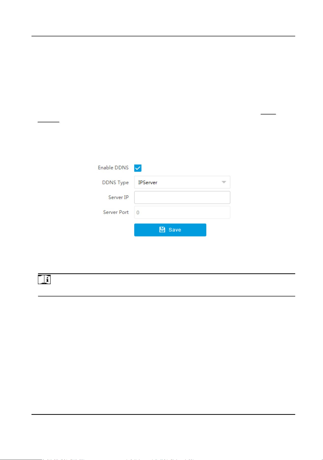
9.4 Set DDNS
You can use the Dynamic DNS (DDNS) for network access. The dynamic IP address of the device can
be mapped to a domain name resoluon server to realize the network access via domain name.
Before You Start
●
Register the domain name on the DDNS server.
●
Set the LAN IP address, subnet mask, gateway, and DNS server parameters. Refer to
Set IP
Address for details.
●
Complete port mapping. The default ports are 80, 8000, and 554.
Steps
1.
Go to Conguraon → Network → Network Parameters → DDNS .
Figure 9-4 Set DDNS
2.
Check Enable DDNS.
3.
Enter the server address and other informaon.
Note
You can select IPServer, DynDNS, and NO-IP for the DDNS type.
4.
Click Save.
5.
Access the device.
By Browsers
Enter the domain name in the browser address bar to access the device.
By Client Soware Add domain name to the client soware. Refer to the client soware
manual for specic adding methods.
9.5 Set SNMP
You can set the SNMP network management protocol to get the alarm event and excepon
messages in network transmission.
Smart Monitoring Camera User Manual
73
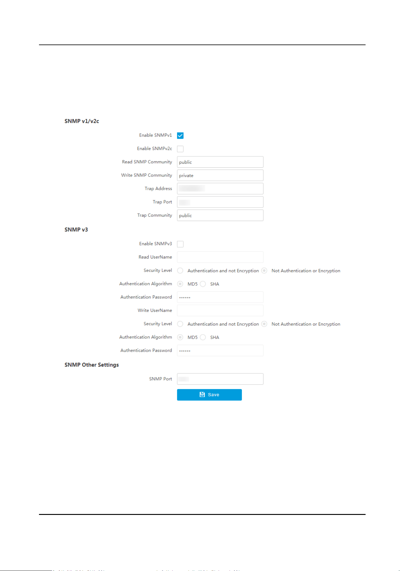
Before You Start
Download the SNMP soware and manage to receive the device informaon via SNMP port.
Steps
1.
Go to
Conguraon → Network → Network Parameters → SNMP .
Figure 9-5 Set SNMP
2.
Check Enable SNMPv1/Enable SNMP v2c/Enable SNMPv3.
Smart Monitoring Camera User Manual
74
Note
●
The SNMP version you select should be the same as that of the SNMP soware.
●
Use dierent versions according to the security levels required. SNMP v1 is not secure and
SNMP v2 requires password for access. SNMP v3 provides encrypon and if you use the third
version, HTTPS protocol must be enabled.
3.
Set the SNMP parameters.
4.
Click Save.
9.6 Set QoS
QoS (Quality of Service) can help improve the network delay and network
congeson by seng
the priority of data sending.
Note
QoS needs support from network devices such as routers and switches.
Steps
1.
Go to Conguraon → Network → Network Parameters → QoS .
2.
Enable DSCP according to the actual needs and set the value.
Note
Network can idenfy the priority of data transmission. The bigger the DSCP value is, the higher
the priority is. Same sengs need to be set in the router for conguraon.
3.
Click Save.
9.7 Connect to
Plaorm
9.7.1 Set Arm Host
The device can upload the captured pictures via the arm host.
Steps
Note
For level 1 arm, the pictures can be uploaded normally. If uploading failed, the device will upload
again. For level 2 arm, the pictures will be uploaded once. No more upload if uploading failed. For
level 3 arm, pictures will not be uploaded.
1.
Go to Conguraon → Network → Data Connecon → Arm Upload .
Smart Monitoring Camera User Manual
75
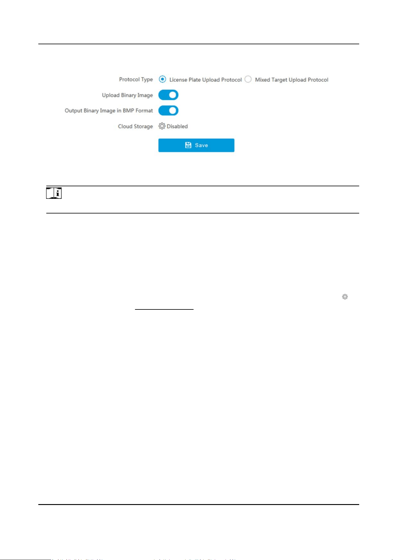
Figure 9-6 Set Arm Host
2.
Select Protocol Type.
Note
Supported funcons vary with dierent models. The actual device prevails.
License Plate Upload Protocol
Uploads arming alarm images of the license plate. You can enable Upload Binary Image if you
need to upload binary images full of black or white pixel points. Enable Output Binary Image
in BMP Format if you want to output images in this format.
Mixed Target Upload Protocol
Uploads images of mulple targets such as humans and vehicles. You can enable the body
property to recognize clothes, bags, and other
properes.
3.
Oponal: If you want to save the alarm informaon and pictures to the cloud storage, click to
set Cloud Storage. Refer to Set Cloud Storage for details.
4.
Click Save.
9.7.2 Set SDK Listening
The SDK listening can be used to receive the uploaded informaon and pictures of the device
arming alarm.
Before You Start
The listening service has been enabled for the SDK listening, and the network communicaon with
the device is normal.
Steps
1.
Go to
Conguraon → Network → Data Connecon → SDK Listening .
Smart Monitoring Camera User Manual
76
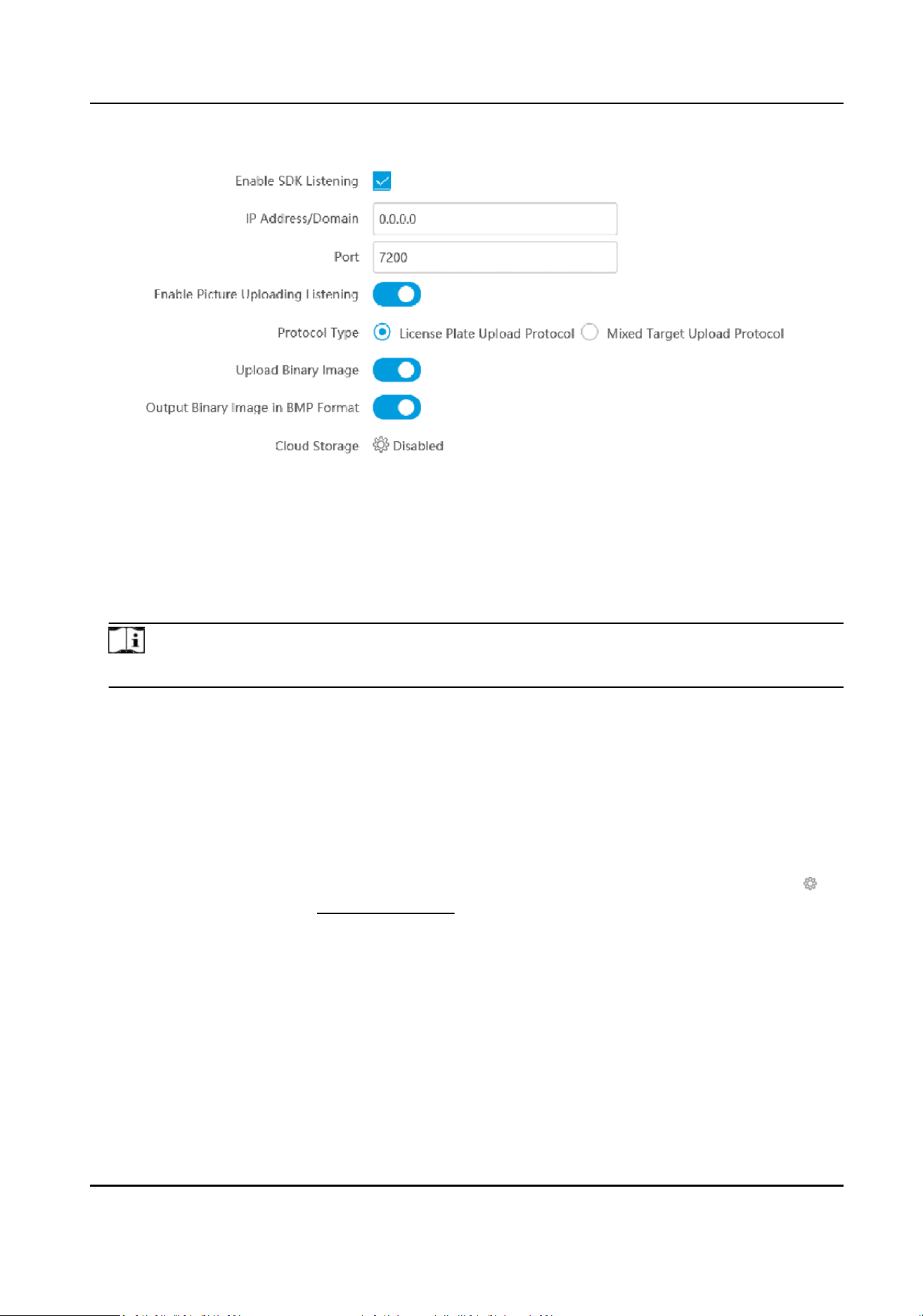
Figure 9-7 Set SDK Listening
2.
Enable SDK listening.
3.
Set IP Address/Domain and Port if you need to upload the alarm informaon and pictures.
4.
Oponal: The device will transmit images via the SDK listening if you enable the picture
uploading listening.
5.
Select Protocol Type.
Note
Supported funcons vary with dierent models. The actual device prevails.
License Plate Upload Protocol
Uploads arming alarm images of the license plate. You can enable Upload Binary Image if you
need to upload images which are full of black or white pixel points. Enable Output Binary
Image in BMP Format if you want to output images in this format.
Mixed Target Upload Protocol
Uploads images of
mulple targets such as humans and vehicles. You can enable the body
property to recognize clothes, bags, and other properes.
6.
Oponal: If you want to save the alarm informaon and pictures to the cloud storage, click to
set Cloud Storage. Refer to Set Cloud Storage for details.
7.
Click Save.
9.7.3 Set ISAPI Listening
ISAPI listening and SDK listening are mutually exclusive protocols. If you enable the picture
uploading listening, the device will transmit images via the SDK listening. If not, the device will
upload images via ISAPI protocol
aer the ISAPI parameters are set.
Smart Monitoring Camera User Manual
77
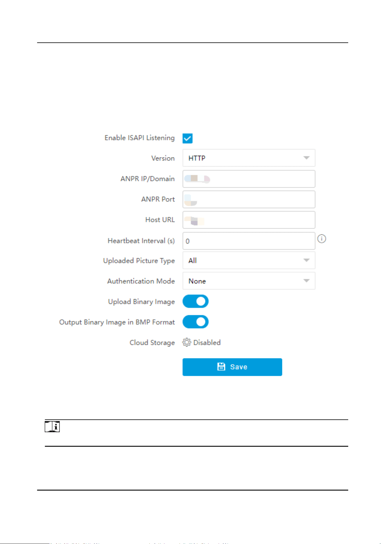
Before You Start
The listening service has been enabled for the ISAPI host, and the network communicaon with
the device is normal.
Steps
1.
Go to
Conguraon → Network → Data Connecon → ISAPI Listening .
2.
Enable the ISAPI listening.
Figure 9-8 Set ISAPI Listening
3.
Set ANPR IP/Domain, ANPR Port, and Host URL.
4.
Enter Heartbeat Interval.
Note
If you set it as 0, the heartbeat is disabled.
5.
Set Uploaded Picture Type.
Smart Monitoring Camera User Manual
78

6.
Select Authencaon Mode and set corresponding parameters to guarantee that only the
authorized users can access the device.
Note
If you select None, the device will not verify the authencaon condion of the access users. It
is recommended to select an authencaon mode to guarantee the device informaon security.
7.
Oponal: Enable Upload Binary Image if you need to upload images which are full of black or
white pixel points.
Note
Enable Output Binary Image in BMP Format if you want to output images in this format.
8.
Oponal: If you want to save the alarm informaon and pictures to the cloud storage, click to
set Cloud Storage. Refer to Set Cloud Storage for details.
9.
Click Save.
9.7.4 Connect to ISUP
Plaorm
ISUP is a plaorm access protocol. The device can be remotely accessed via this plaorm.
Before You Start
●
Create the device ID on ISUP plaorm.
●
Ensure the device can communicate with the plaorm normally.
Steps
1.
Go to
Conguraon → Network → Data Connecon → ISUP .
Smart Monitoring Camera User Manual
79
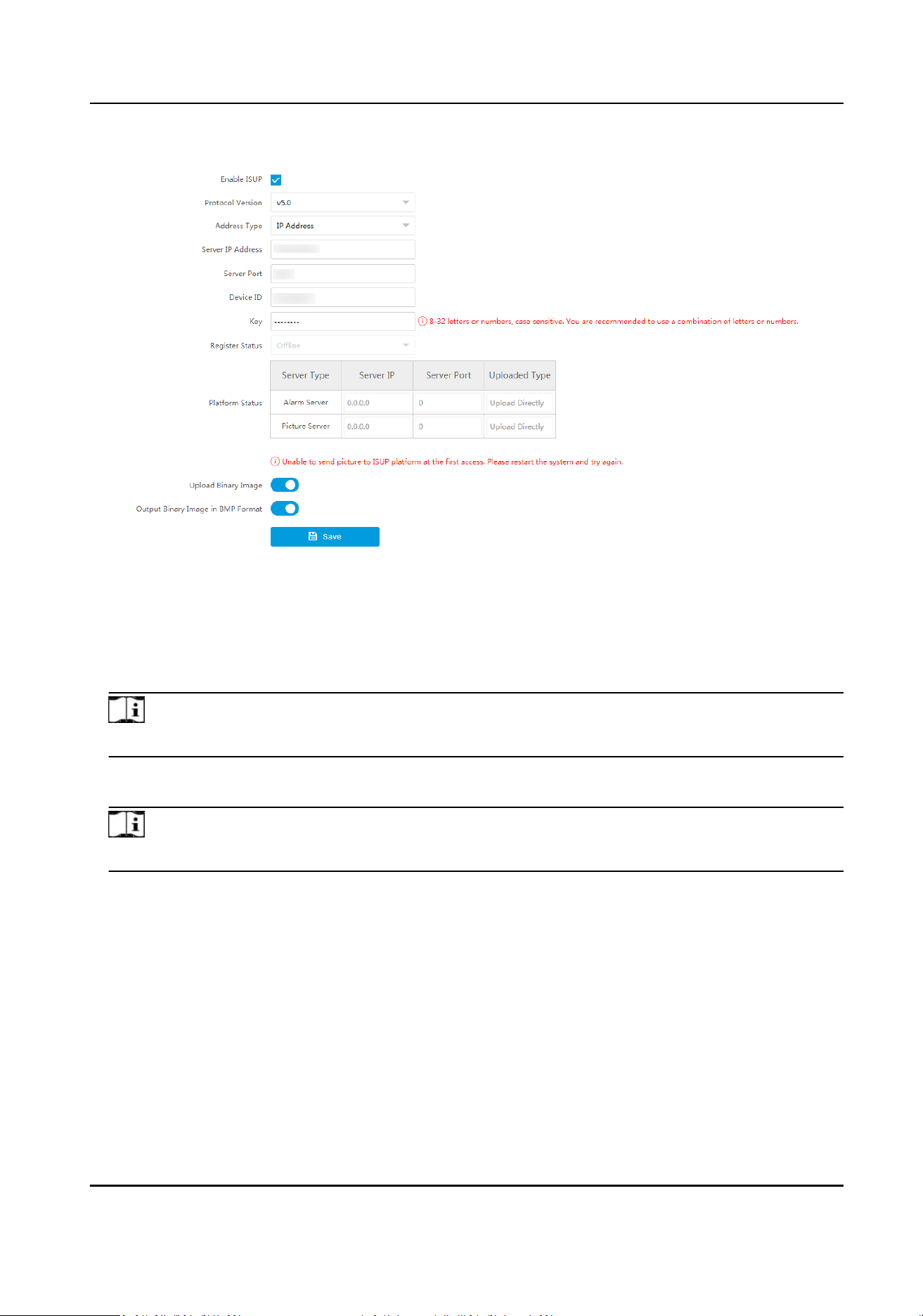
Figure 9-9 Connect to ISUP Plaorm
2.
Check Enable ISUP.
3.
Select Protocol Version.
4.
Select Address Type.
5.
Enter Sever IP Address, Server Port, and Device ID.
Note
You need to enter Key if you select Protocol Version as v5.0.
6.
Oponal: For protocol v5.0, you can enable Upload Binary Image if you need to upload images
which are full of black or white pixel points.
Note
Enable Output Binary Image in BMP Format if you want to output images in this format.
7.
Click Save.
What to do next
When the registraon status is online, you can manage the device via the plaorm or server.
9.7.5 Connect to OTAP
The device can be accessed to the ISC
plaorm via OTAP protocol to realize live view, view incident
informaon, manage the devices, etc. via the plaorm.
Smart Monitoring Camera User Manual
80
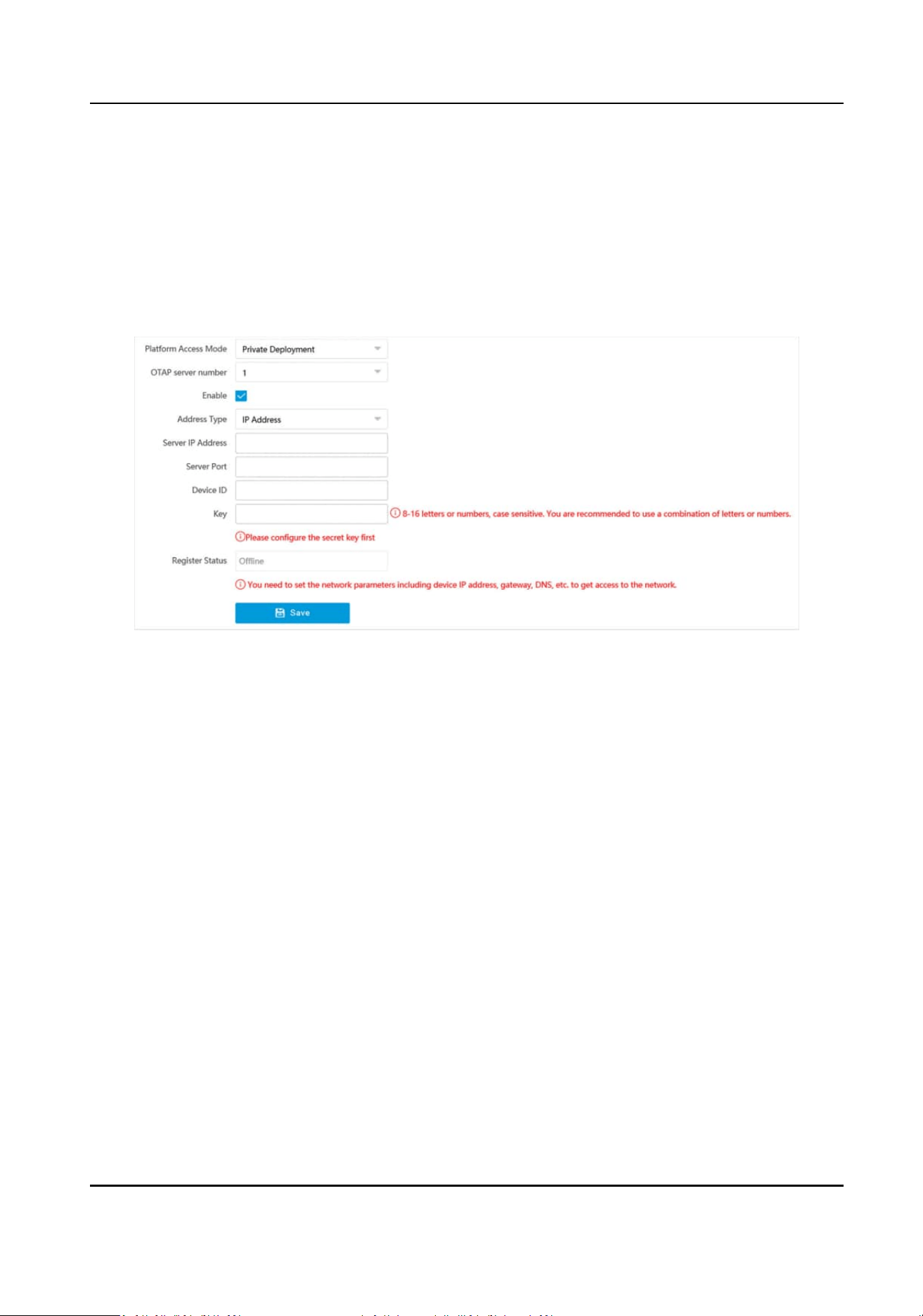
Before You Start
●
Ensure the device can communicate with the plaorm normally.
●
Disable the other plaorm accesses conicng with OTAP.
Steps
1.
Go to
Conguraon → Network → Data Connecon → OTAP .
2.
Select Plaorm Access Mode as Private Deployment.
3.
Check Enable.
Figure 9-10 Connect to OTAP
4.
Set corresponding parameters.
Address Type
Select the address type of the connected
plaorm or server.
Server IP Address/Server Domain Name
The IP address or domain name of the connected plaorm or server.
Server Port
The port of the connected plaorm or server.
Device ID
The device ID should be the same with the added one on the OTAP plaorm.
Key
Set a custom key to encrypt the data connecon between the device and the plaorm or
server.
5.
Click Save.
What to do next
When the
registraon status is online, you can manage the device via the plaorm or server.
Smart Monitoring Camera User Manual
81
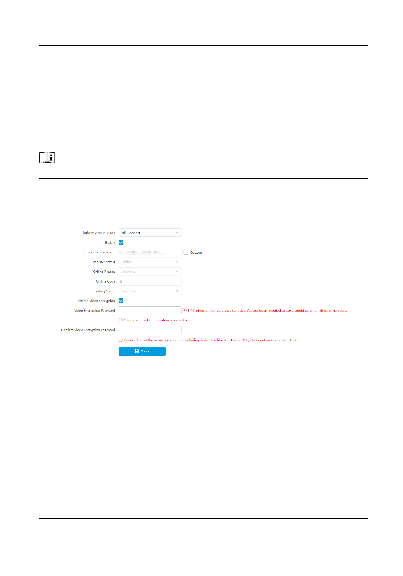
9.7.6 Connect to Hik-Connect
The device can be remotely accessed via Hik-Connect.
Before You Start
●
Connect the device to the Internet.
●
Set the IP address, subnet mask, gateway, and DNS server of the LAN.
Steps
Note
This funcon varies with dierent models. The actual device prevails.
1.
Enable Hik-Connect in two ways.
-
Get access to Hik-Connect V2.0. Go to Conguraon → Network → Data Connecon →
OTAP , and select Plaorm Access Mode as Hik-Connect. Check Enable.
Figure 9-11 Connect to Hik-Connect (V2.0)
-
Get access to Hik-Connect V3.0. Go to Conguraon → Network → Data Connecon → Hik-
Connect Plaorm . Check Enable Hik-Connect Plaorm.
Smart Monitoring Camera User Manual
82
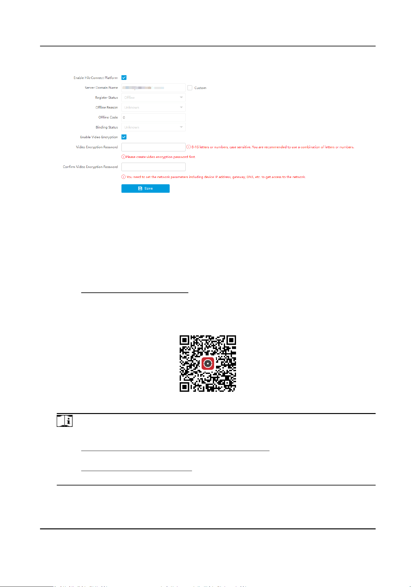
Figure 9-12 Connect to Hik-Connect (V3.0)
2.
Oponal: If you have allocated a custom server, check Custom and enter the custom Server
Domain Name.
3.
Oponal: Check Enable Video Encrypon and set Video Encrypon Password to encrypt the
videos transmission. Conrm the password.
4.
Click Save.
5.
Add the device to Hik-Connect.
1) Get and install Hik-Connect
applicaon by the following ways.
●
Visit hps://appstore.hikvision.com to download the applicaon according to your mobile
phone system.
●
Visit the
ocial site of our company. Then go to Support → Tools → Hikvision App Store .
●
Scan the QR code below to download the
applicaon.
Figure 9-13 Hik-Connect
Note
If errors like "Unknown app" occur during the installaon, solve the problem in two ways.
●
Visit hps://appstore.hikvision.com/stac/help/index.html to refer to the
troubleshoong.
●
Visit
hps://appstore.hikvision.com/ , and click Installaon Help at the upper right corner
of the interface to refer to the
troubleshoong.
2) Start the applicaon and register a user account to log in.
Smart Monitoring Camera User Manual
83

3) Add device by the serial No. on the device body and the vericaon code.
Note
Refer to the user manual of Hik-Connect applicaon for details.
9.8 Set Integraon Protocol
You can connect the device via ONVIF protocol.
Steps
1.
Go to Conguraon → Network → Data Connecon → Integraon Protocol .
2.
Check Enable.
3.
Add a user.
1) Click Add.
2) Set user name, password, and user level, and
conrm the password.
3) Click OK.
4)
Oponal: You can select the added user and click Modify to edit the user informaon, or click
Delete to delete the user.
4.
Click Save.
Result
Only the added users can access the device via ONVIF protocol.
Smart Monitoring Camera User Manual
84
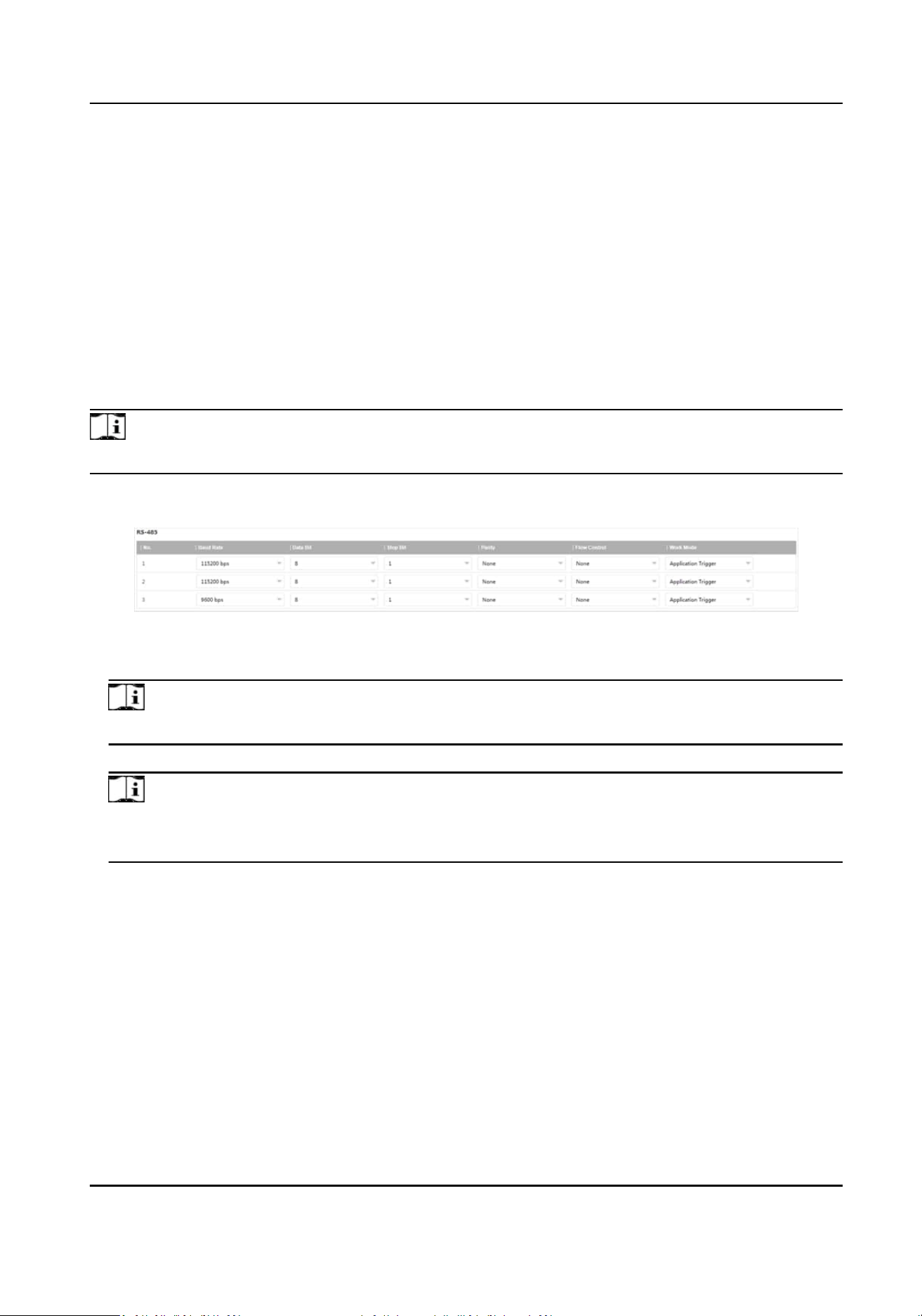
Chapter 10 Serial Port Conguraon
10.1 Set RS-485
Set RS-485 parameters if the device needs to be connected to other peripheral devices controlled
by RS-485 serial port.
Before You Start
The corresponding device has been connected via the RS-485 serial port.
Steps
Note
The number of available RS-485 serial port varies with dierent models.
1.
Go to Conguraon → System → System Sengs → Serial Port → RS-485 .
Figure 10-1 Set RS-485
2.
Set Baud Rate, Data Bit, Stop Bit, etc.
Note
The parameters should be same with those of the connected device.
3.
Set Work Mode.
Note
●
The supported work modes vary with dierent models. The actual device prevails.
●
You need to reboot the device aer eding the work mode to take eect.
Applicaon Trigger
Select it when a signal trigger device (such as a radar) is connected to the RS-485 serial port
of the device.
Transparent Channel
Select it when the other peripheral device is connected to the RS-485 serial port of the device
for
communicaon transmission.
GPS
Select it when a GPS device is connected to the RS-485 serial port of the device to receive
posioning informaon.
Smart Monitoring Camera User Manual
85
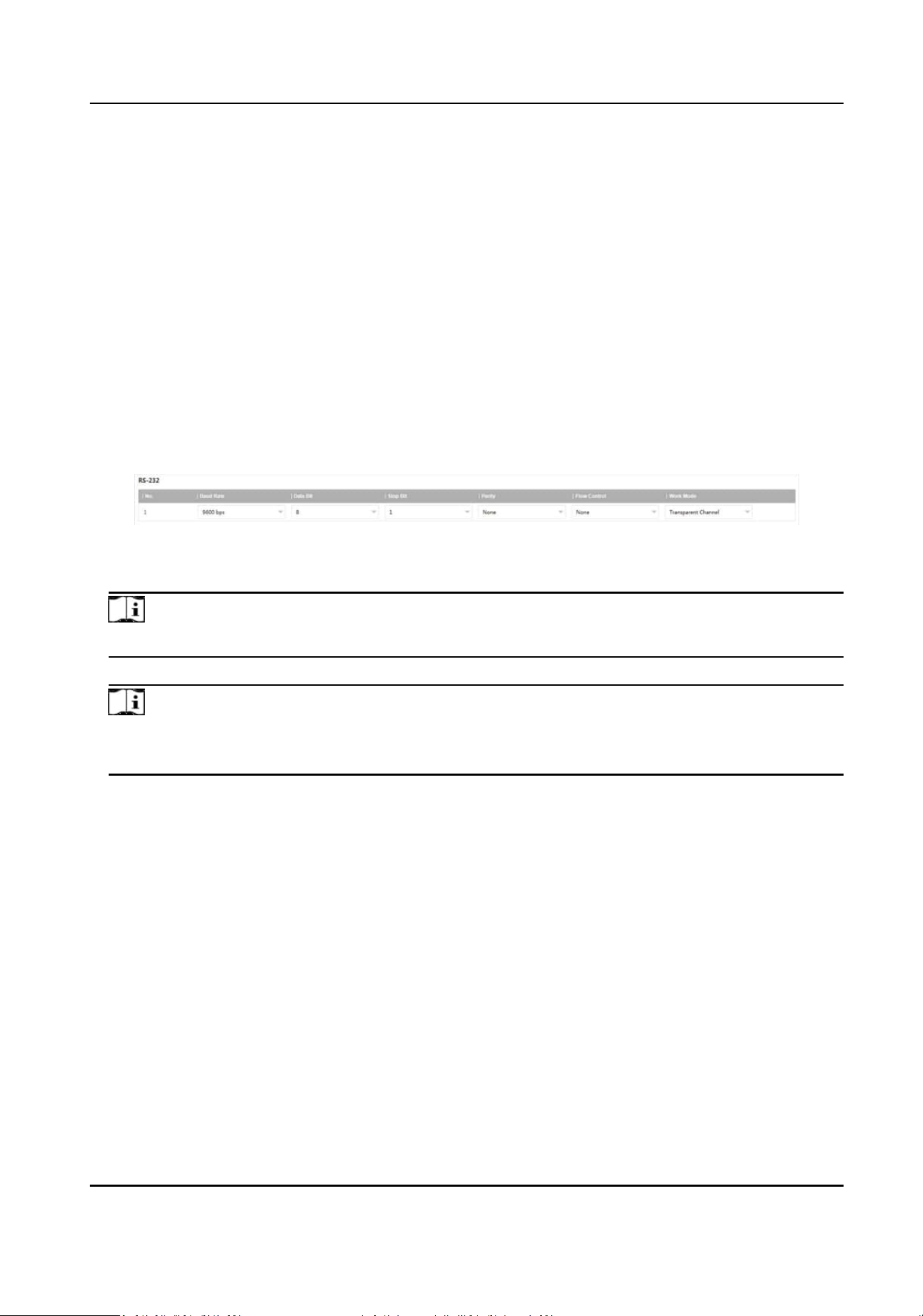
Trac Signal Controller Mode
Select it when a trac signal controller is connected to the RS-485 serial port of the device
for communicaon transmission.
4.
Click Save.
10.2 Set RS-232
Set RS-232 parameters if you need to debug the device via RS-232 serial port.
Before You Start
The debugging device has been connected via the RS-232 serial port.
Steps
1.
Go to
Conguraon → System → System Sengs → Serial Port → RS-232 .
Figure 10-2 Set RS-232
2.
Set Baud Rate, Data Bit, Stop Bit, etc.
Note
The parameters should be same with those of the connected device.
3.
Select Work Mode.
Note
●
The supported work modes vary with dierent models. The actual device prevails.
●
You need to reboot the device aer eding the work mode to take eect.
Console
Select it when you need to debug the device via RS-232 serial port.
Transparent Channel
Select it, and the network command can be transmied to RS-232 control command via the
RS-232 serial port.
Narrow Bandwidth Transmission
Reserved.
4.
Click Save.
Smart Monitoring Camera User Manual
86

Chapter 11 Event and Alarm
11.1 Excepon Alarm
Set excepon alarm when the network is disconnected, the IP address is conicted, etc.
Steps
Note
The supported excepon types vary with dierent models. The actual device prevails.
1.
Go to Conguraon → Event → Alarm Linkage → Excepon .
2.
Select the
excepon type(s) and the linkage method.
3.
Click Save.
11.2 Set Email
When the email is enabled and set, the device will send an email nocaon to all designated
receivers if an alarm event is detected.
Before You Start
Set the DNS server before using the email
funcon. Go to Conguraon → Network → Network
Parameters → Network Interface for DNS sengs.
Steps
1.
Go to
Conguraon → Network → Data Connecon → Email .
2.
Check Enable Email.
Smart Monitoring Camera User Manual
87
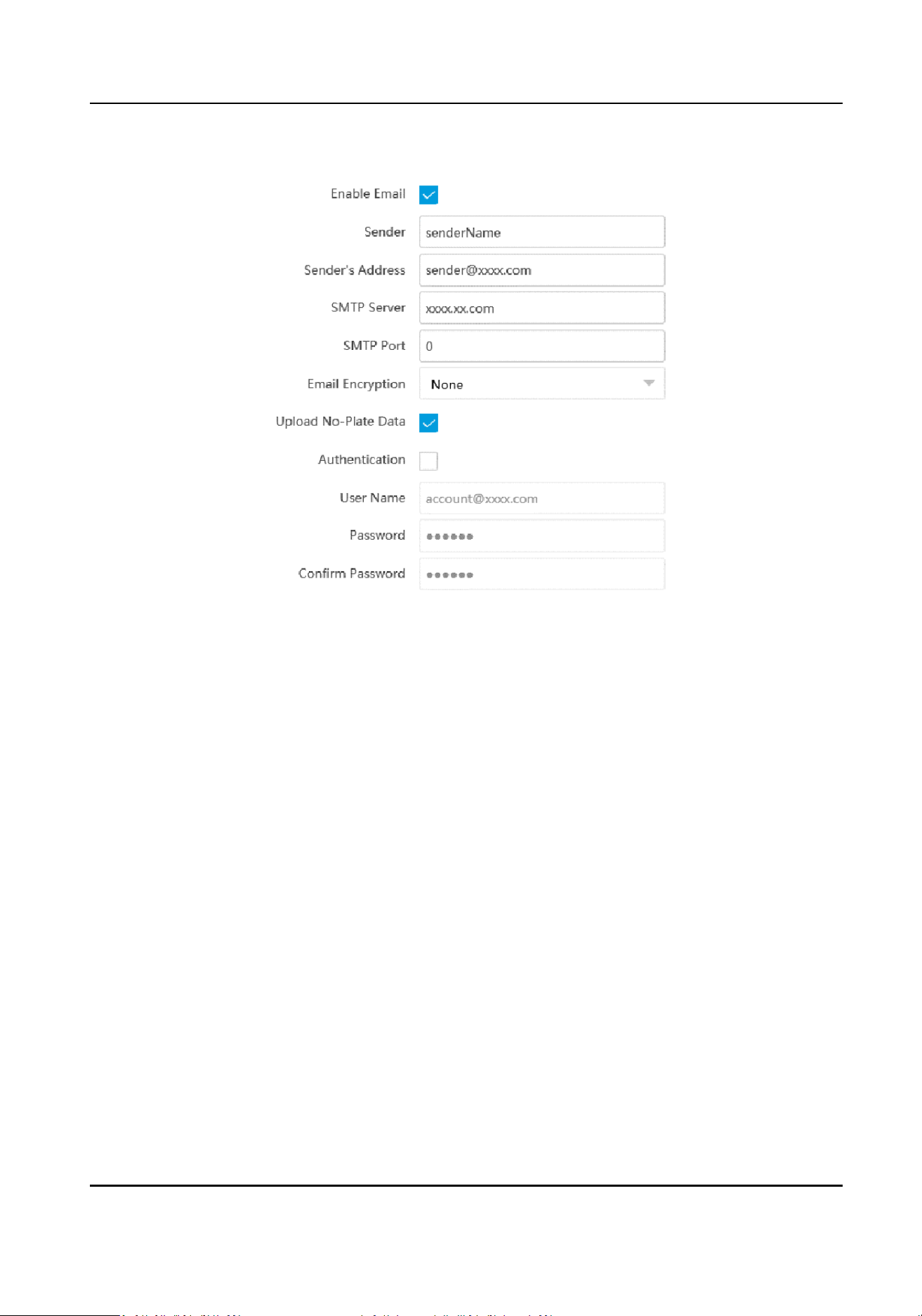
Figure 11-1 Set Email
3.
Set email parameters.
1) Enter the sender's email
informaon, including Sender, Sender's Address, SMTP Server, and
SMTP Port.
2) Select Email
Encrypon.
None
Emails are sent without encrypon.
TLS
Emails are sent aer being encrypted by TLS.
3)
Oponal: If you want to upload no-plate data, check Upload No-Plate Data.
4) Oponal: If your email server requires authencaon, check Authencaon and enter your
user name and password to log in to the server.
5) Enter the receiver's
informaon, including the receiver's name and address.
6) Oponal: Click Test to see if the funcon is well congured.
4.
Click Save.
11.3 Set Email Event
When the set event occurs, the device can be set to send an email with alarm informaon to the
user.
Smart Monitoring Camera User Manual
88

Before You Start
The email has been enabled and related email parameters have been congured.
Steps
1.
Go to
Conguraon → Event → Alarm Linkage → Email Event .
2.
Check Enable to trigger an email alarm.
3.
Click Save.
Smart Monitoring Camera User Manual
89

Chapter 12 Safety Management
12.1 Manage User
The administrator can add, modify, or delete other accounts, and grant dierent permissions to
dierent user levels.
Steps
1.
Go to Conguraon → System → User Management → User List .
2.
Select Password Level.
The password level of the added user should conform to the selected level.
3.
Add a user.
1) Click Add.
2) Enter User Name and select Type.
3) Enter Admin Password, New Password, and
conrm the password.
Cauon
To increase security of using the device on the network, please change the password of your
account regularly. Changing the password every 3 months is recommended. If the device is
used in high-risk environment, it is recommended that the password should be changed every
month or week.
4) Assign remote permission to users based on needs.
User
Users can be assigned permission of viewing live video and changing their own passwords,
but no permission for other
operaons.
Operator
Operators can be assigned all permission except for operaons on the administrator and
creang accounts.
5) Click OK.
4.
Oponal: You can do the following operaons.
Change the password and permission
Click to change the password and permission.
Delete the user Click to delete the user.
12.2 Enable User Lock
To raise the data security, you are recommended to lock the current IP address.
Steps
1.
Go to Conguraon → System → Security → Security Service → Soware .
2.
Check Enable User Lock.
Smart Monitoring Camera User Manual
90

3.
Click Save.
Result
When the
mes you entered incorrect passwords have reached the limit, the current IP address
will be locked
automacally.
12.3 Set SSH
To raise network security, you are recommended to disable SSH service. The conguraon is only
used to debug the device for the professionals.
Steps
1.
Go to
Conguraon → System → Security → Security Service → Soware .
2.
Enable or disable SSH Service, and set SSH Port if you enable the funcon.
3.
Click Save.
12.4 Prohibit PING
You can prohibit the external devices to operate network connecon volume test to the current
device.
Steps
1.
Go to Conguraon → System → Security → Security Service → Soware
2.
Enable Prohibit PING.
3.
Click Save.
12.5 Enable System Log Service
The security audit logs refer to the security operaon logs. You can search and analyze the security
log
les of the device so as to nd out the illegal intrusion and troubleshoot the security events.
Security audit logs can be saved on device internal storage. The log will be saved every half hour
aer device boong. Due to limited storage space, you are recommended to save the logs on a log
server.
Steps
1.
Go to Conguraon → System → Security → Security Service → Log Audit Service .
2.
Enable system log service.
3.
Enter IP Address and Port of the log server.
4.
Click Save.
Result
The device will upload the security audit logs to the log server regularly.
Smart Monitoring Camera User Manual
91

12.6 Set Timeout Logout
You can improve network access security by seng meout logout.
Steps
1.
Go to
Conguraon → System → Security → Security Service → Timeout Logout .
2.
Enable meout logout for stac page.
3.
Set Max. Timeout.
4.
Click Save.
Result
When the page
stac me exceeds the set me, the device will automacally log out.
12.7 Set Password Validity Period
You can improve network access security by seng password validity period.
Steps
1.
Go to Conguraon → System → Security → Security Service → Password Validity Period .
2.
Select Validity Type.
-
Select Permanent. The password will be permanently valid.
-
Select Daily and set Password Expiry Time. It will prompt you that the password is expired
according to the set password expiry me, and you need to set the new password.
3.
Click Save.
12.8 Set SDK Protocol
Authencaon Mode
When you need to operate development integraon or data collecon via SDK protocol, you are
recommended to enable SDK protocol authencaon to enhance the informaon security.
Steps
1.
Go to Conguraon → System → Security → Security Service → SDK Service Module .
2.
Select SDK Protocol
Authencaon Mode.
Note
You are recommended to select Safety Mode. In this mode, the device cannot be logged in via
an inverble password of SDK protocol, which can enhance the informaon security.
3.
Click Save.
Smart Monitoring Camera User Manual
92

12.9 Set RTSP Authencaon
You can improve network access security by seng RTSP authencaon.
Steps
1.
Go to
Conguraon → System → Security → Security Sengs .
2.
Select RTSP Authencaon.
digest
The device only supports digest
authencaon.
3.
Click Save.
12.10 Set IP Address Filtering
You can set the IP addresses allowable and not allowable to access the device.
Steps
1.
Go to
Conguraon → System → Security → Security Sengs .
2.
Check Enable IP Address Filtering.
3.
Set Filtering Mode.
Blocklist Mode
The added IP addresses are not allowed to access the device.
Allowlist Mode
The added IP addresses are allowed to access the device.
4.
Click Add, enter the IP address, and click OK.
Note
The IP address only refers to the IPv4 address.
5.
Oponal: Edit, delete, or clear the added IP addresses.
6.
Click Save.
12.11 Set HTTPS
12.11.1 Create and Install Self-signed Cercate
HTTPS is a network protocol that enables encrypted transmission and identy authencaon,
which improves the security of remote access.
Steps
1.
Go to Conguraon → Network → Network Parameters → HTTPS .
2.
Select Create Self-signed
Cercate.
Smart Monitoring Camera User Manual
93

3.
Click Create.
4.
Follow the prompt to enter Country/Region, Domain/IP, Validity, and other parameters.
5.
Click OK.
Result
The device will install the self-signed
cercate by default.
12.11.2 Install Authorized Cercate
If the demand for external access security is high, you can create and install authorized cercate
via HTTPS protocol to ensure the data transmission security.
Steps
1.
Go to
Conguraon → Network → Network Parameters → HTTPS .
2.
Select Create cercate request rst and connue the installaon.
3.
Click Create.
4.
Follow the prompt to enter Country/Region, Domain/IP, Validity, and other parameters.
5.
Click Download to download the
cercate request and submit it to the trusted authority for
signature.
6.
Import
cercate to the device.
-
Select Signed
cercate is available, start the installaon directly. Click Browse and Install to
import the cercate to the device.
-
Select Create the cercate request rst and connue the installaon. Click Browse and
Install to import the cercate to the device.
7.
Click Save.
Smart Monitoring Camera User Manual
94

Chapter 13 Maintenance
13.1 View Device Informaon
Basic Informaon and Algorithms Library Version
Go to Conguraon → System → System Sengs → Basic Informaon to view the basic
informaon and algorithms library version of the device.
You can edit Device Name and Device No. The device No. is used to control the device. It is
recommended to reserve the default value.
Device Status
Go to Conguraon → System → System Sengs → Device Status to view the device status.
13.2 Synchronize Time
Synchronize the device me when it is inconsistent with the actual me.
Steps
1.
Go to
Conguraon → System → System Sengs → Time Sengs .
2.
Select Time Zone.
3.
Select Sync Mode.
NTP
Synchronizaon
Select it to synchronize the device me with that of the NTP server. Set Server IP, NTP Port,
and Interval. Click NTP Test to test if the
connecon between the device and the server is
normal.
Manual Synchronizaon
Select it to synchronize the device me with that of the computer. Set me manually, or
check Sync. with computer
me.
Satellite Time
Select it to synchronize the device me with that of the satellite. Set Interval.
SDK
If the remote host has been set for the device, select it to synchronize me via the remote
host.
ONVIF
Select it to synchronize me via the third-party device.
PTP
Smart Monitoring Camera User Manual
95

Select it to synchronize me more accurately. Precision Time Protocol (PTP) is a protocol to
synchronize clocks in a computer network, similar to NTP. NTP is accurate, under ten
milliseconds. PTP, however, is accurate up to less than a microsecond and is measured in
nanoseconds.
No
Select it to disable
me synchronizaon.
All
Select it, and you can select any mode above.
Note
The me synchronizaon modes vary with dierent models. The actual device prevails.
4.
Click Save.
13.3 Set DST
If the region where the device is located adopts Daylight Saving Time (DST), you can set this
funcon.
Steps
1.
Go to Conguraon → System → System Sengs → DST .
2.
Check Enable DST.
3.
Set Start Time, End Time, and DST Bias.
4.
Click Save.
13.4 Reboot
When the device needs to be rebooted, reboot it via the soware instead of cung o the power
directly.
Steps
1.
Go to
Conguraon → System → Maintenance → Upgrade & Maintenance → Device
Maintenance .
2.
Click Reboot.
3.
Click OK to reboot the device.
Note
You can also click Reboot on the upper right corner of the page to reboot the device.
Smart Monitoring Camera User Manual
96

13.5 Restore Parameters
When the device is abnormal caused by the incorrect set parameters, you can restore the
parameters.
Steps
1.
Go to Conguraon → System → Maintenance → Upgrade & Maintenance → Device
Maintenance .
2.
Select the
restoraon mode.
-
Click Restore, and select the parameters to be saved instead of being restored. Click OK. Then
the parameters except the IP parameters, user parameters, and the saved parameters will be
restored to the default sengs.
-
Click Restore Factory Sengs and click OK to restore all the parameters to the factory
sengs.
3.
Click OK.
13.6 Export Parameters
You can export the parameters of one device, and import them to another device to set the two
devices with the same parameters.
Steps
1.
Go to
Conguraon → System → Maintenance → Upgrade & Maintenance → Data Export .
2.
Click Export aer Conguring Parameters.
3.
Set an
encrypon password, conrm the password, and click OK.
Note
The password is used for imporng the conguraon le of the current device to other devices.
4.
Select the saving path, and enter the le name.
5.
Click Save.
13.7 Export Debug File
The technicians can export the debug le to troubleshoot and maintain the device.
Steps
1.
Go to
Conguraon → System → Maintenance → Upgrade & Maintenance → Data Export .
2.
Click Export aer Debug File.
3.
Select the saving path, and enter the le name.
4.
Click Save.
Smart Monitoring Camera User Manual
97
13.8 Export Diagnosis Informaon
The technicians can export the diagnosis informaon to troubleshoot and maintain the device.
Steps
1.
Go to
Conguraon → System → Maintenance → Upgrade & Maintenance → Data Export .
2.
Click Export aer Diagnosis Informaon.
3.
Select the saving path, and enter the
le name.
4.
Click Save.
13.9 Upgrade
Upgrade the system when you need to update the device version.
Before You Start
Prepare the upgrade
le. If the upgrade le is a compressed package, it needs to be decompressed
into the .dav format.
Steps
1.
Go to Conguraon → System → Maintenance → Upgrade & Maintenance → Upgrade .
2.
Click Browse to select the upgrade
le.
3.
Click Upgrade.
4.
Click OK in the popup window.
Note
The upgrade process will take 1 to 10 minutes. Do not cut o the power supply.
Result
The device will reboot automacally aer upgrade.
13.10 Import
Conguraon File
Import the conguraon le of another device to the current device to set the same parameters.
Before You Start
Save the conguraon le to the computer.
Steps
Cauon
Imporng conguraon le is only available to the devices of the same model and same version.
1.
Go to Conguraon → System → Maintenance → Upgrade & Maintenance → Advanced
Sengs → Data Import .
Smart Monitoring Camera User Manual
98
2.
Select Imporng Method.
Note
If you select Import Part, check the parameters to be imported.
3.
Click Browse to select the conguraon le.
4.
Click Import.
5.
Enter the password which is set when the
conguraon le is exported, and click OK.
6.
Click OK on the popup window.
Result
The parameters will be imported, and the device will reboot.
13.11 Log
13.11.1 Enable Log According to Module
You can enable the log according to the module for debugging.
Steps
Note
The funcon varies with dierent models. The actual device prevails.
1.
Go to Conguraon → System → Maintenance → Debug → Log .
2.
Check the module(s) according to your needs.
Note
If you want to disable the log automacally, you can enable auto close log and set close me.
3.
Click Save.
13.11.2 Search Log
Log helps to locate and troubleshoot problems.
Steps
1.
Go to Conguraon → System → Maintenance → Log Search .
2.
Set search condions.
3.
Click Search.
The matched log les will be displayed on the log list.
4.
Oponal: Click Export to save the log les to your computer.
Smart Monitoring Camera User Manual
99
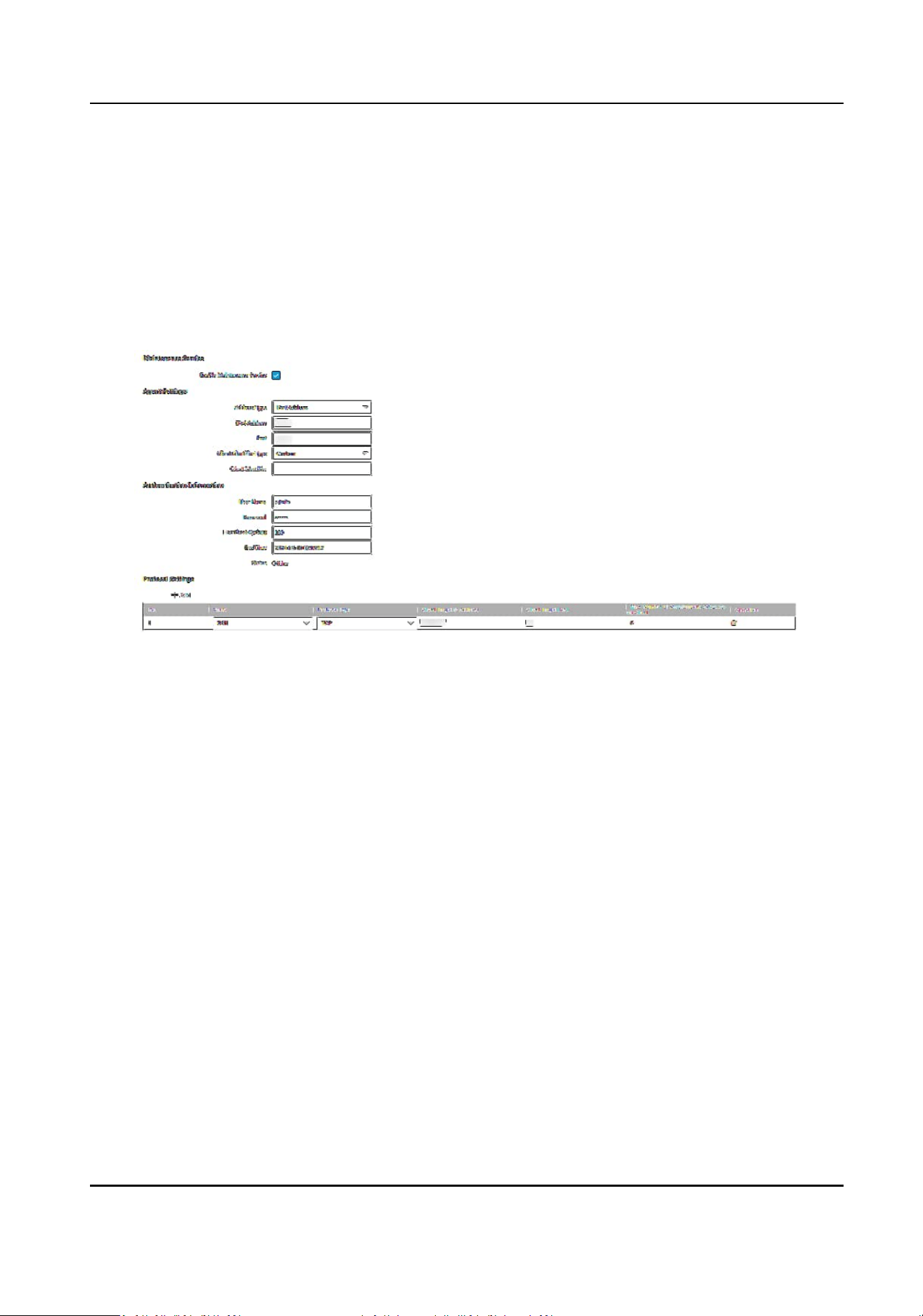
13.12 Enable Maintenance Service
If you want to realize remote camera maintenance and debug via the plaorm server, enable
maintenance service and set the access mode.
Steps
1.
Go to Conguraon → System → Maintenance → Maintenance Service .
2.
Enable maintenance service.
Figure 13-1 Maintenance Service
3.
Set agent parameters.
1) Select Address Type.
2) Set the IP address/domain name and port of the agent.
3) Select Client
Idener Type and set Client Idener according to the actual supporng
condions of the camera. The idener serves as a unique mark of the camera.
4.
Set the
authencaon informaon.
User Name/Password
The user name and password of the camera for the authencaon via the plaorm server
access.
Heartbeat Cycle(s)
You are recommended to keep the default value.
End Time
The camera will disconnect with the
plaorm server when reaching the set end me.
5.
Set protocol parameters.
1) Click Add to add a protocol.
2) Set the corresponding parameters of the protocol.
Smart Monitoring Camera User Manual
100

Note
You can login and access up to 5 cameras (clients) simultaneously via HTTP or SSH protocol.
6.
Click Save.
What to do next
Aer sengs, refresh the interface and check the authencaon status of the camera. If the status
is online, you can access and debug the camera via the
plaorm server.
Smart Monitoring Camera User Manual
101

UD37620B