

Monitor • User Manual
i
Legal Information
About this Product
This product can only enjoy the after-sales service support in the country or region where the
purchase is made.
Acknowledgment of Intellectual Property Rights
● Hikvision owns the copyrights and/or patents related to the technology embodied in the
Products described in this Document, which may include licenses obtained from third parties.
● Any part of the Document, including text, pictures, graphics, etc., belongs to Hikvision. No part
of this Document may be excerpted, copied, translated, or modified in whole or in part by any
means without written permission.
● and other Hikvision's trademarks and logos are the properties of Hikvision in
various jurisdictions.
● Other trademarks and logos mentioned are the properties of their respective owners.
● The terms HDMI and HDMI High-Definition Multimedia Interface, and the HDMI Logo
are trademarks or registered trademarks of HDMI Licensing Administrator, Inc. in the United
States and other countries.
LEGAL DISCLAIMER
● TO THE MAXIMUM EXTENT PERMITTED BY APPLICABLE LAW, THIS DOCUMENT AND THE
PRODUCT DESCRIBED, WITH ITS HARDWARE, SOFTWARE AND FIRMWARE, ARE PROVIDED "AS
IS" AND "WITH ALL FAULTS AND ERRORS". HIKVISION MAKES NO WARRANTIES, EXPRESS OR
IMPLIED, INCLUDING WITHOUT LIMITATION, MERCHANTABILITY, SATISFACTORY QUALITY, OR
FITNESS FOR A PARTICULAR PURPOSE. THE USE OF THE PRODUCT BY YOU IS AT YOUR OWN RISK.
IN NO EVENT WILL HIKVISION BE LIABLE TO YOU FOR ANY SPECIAL, CONSEQUENTIAL,
INCIDENTAL, OR INDIRECT DAMAGES, INCLUDING, AMONG OTHERS, DAMAGES FOR LOSS OF
BUSINESS PROFITS, BUSINESS INTERRUPTION, OR LOSS OF DATA, CORRUPTION OF SYSTEMS, OR
LOSS OF DOCUMENTATION, WHETHER BASED ON BREACH OF CONTRACT, TORT (INCLUDING
NEGLIGENCE), PRODUCT LIABILITY, OR OTHERWISE, IN CONNECTION WITH THE USE OF THE
PRODUCT, EVEN IF HIKVISION HAS BEEN ADVISED OF THE POSSIBILITY OF SUCH DAMAGES OR
LOSS.
● YOU ACKNOWLEDGE THAT THE NATURE OF THE INTERNET PROVIDES FOR INHERENT SECURITY
RISKS, AND HIKVISION SHALL NOT TAKE ANY RESPONSIBILITIES FOR ABNORMAL OPERATION,
PRIVACY LEAKAGE OR OTHER DAMAGES RESULTING FROM CYBER-ATTACK, HACKER ATTACK,
VIRUS INFECTION, OR OTHER INTERNET SECURITY RISKS; HOWEVER, HIKVISION WILL PROVIDE
TIMELY TECHNICAL SUPPORT IF REQUIRED.
● YOU AGREE TO USE THIS PRODUCT IN COMPLIANCE WITH ALL APPLICABLE LAWS, AND YOU ARE

Monitor • User Manual
ii
SOLELY RESPONSIBLE FOR ENSURING THAT YOUR USE CONFORMS TO THE APPLICABLE LAW.
ESPECIALLY, YOU ARE RESPONSIBLE, FOR USING THIS PRODUCT IN A MANNER THAT DOES NOT
INFRINGE ON THE RIGHTS OF THIRD PARTIES, INCLUDING WITHOUT LIMITATION, RIGHTS OF
PUBLICITY, INTELLECTUAL PROPERTY RIGHTS, OR DATA PROTECTION AND OTHER PRIVACY
RIGHTS. YOU SHALL NOT USE THIS PRODUCT FOR ANY PROHIBITED END-USES, INCLUDING THE
DEVELOPMENT OR PRODUCTION OF WEAPONS OF MASS DESTRUCTION, THE DEVELOPMENT OR
PRODUCTION OF CHEMICAL OR BIOLOGICAL WEAPONS, ANY ACTIVITIES IN THE CONTEXT
RELATED TO ANY NUCLEAR EXPLOSIVE OR UNSAFE NUCLEAR FUEL-CYCLE, OR IN SUPPORT OF
HUMAN RIGHTS ABUSES.
● IN THE EVENT OF ANY CONFLICTS BETWEEN THIS DOCUMENT AND THE APPLICABLE LAW, THE
LATTER PREVAILS.
© Hangzhou Hikvision Digital Technology Co., Ltd. All rights reserved.
Monitor • User Manual
iii
Applicable Models
This manual is applicable to the model: Monitor.
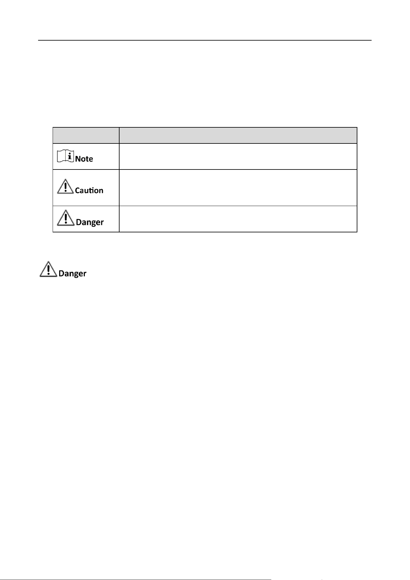
Symbol Conventions
The symbols that may be found in this document are defined as follows.
Safety Instructions
Caution: The device may generate radio interference in indoor environment. Necessary
precautions may be required.
In the use of the product, you must be in strict compliance with the electrical safety
regulations of the nation and region.
Provide a surge suppressor at the inlet opening of the device under special conditions such as
the mountain top, iron tower, and forest.
If the device uses a 3-prong power supply plug, it must be connected to an earthed mains
socket-outlet properly.
The socket-outlet shall be installed near the device and shall be easily accessible.
Do not touch the bare components (such as the metal contacts of the inlets) and wait for at
least 5 minutes, since electricity may still exist after the device is powered off.
CAUTION: Replace the fuse only with the same model to reduce the risk of fire or electric
shock.
The device must be connected to an earthed mains socket-outlet.
Make sure that the power has been disconnected before you wire, install, or disassemble the
device.
CAUTION: This device is for use only with specified bracket (Hikvision's monitor stand). Use
with other (carts, stands, or carriers) may result in instability causing injury.
If the device is equipped with personal music player function, to prevent possible hearing
damage, do not listen at high volume levels for long periods. Refer to datasheet for details.
The interface varies with the models. Please refer to the product datasheet for details.
Symbol
Description
Provides additional information to emphasize or supplement
important points of the main text.
Indicates a potentially hazardous situation, which if not avoided,
could result in equipment damage, data loss, performance
degradation, or unexpected results.
Indicates a hazard with a high level of risk, which if not avoided, will
result in death or serious injury.

Monitor • User Manual
iv
If the device needs to be wired by yourself, select the corresponding wire to supply power
according to the electric parameters labeled on the device. Strip off wire with a standard wire
stripper at corresponding position. To avoid serious consequences, the length of stripped wire
shall be appropriate, and conductors shall not be exposed.
If the device is not working properly, contact the store where the device was purchased or the
nearest service center and do not remove or modify the device in any way. (Our company is
not responsible for problems caused by unauthorized modifications or repairs.)
The device shall not be exposed to water dripping or splashing and that no objects filled with
liquids, such as vases, shall be placed on the equipment.
Ensure correct voltage and wiring of the terminals for connection to mains supply.
The device has been designed, when required, modified for connection to an IT power
distribution system.
identifies the battery holder itself and identifies the positioning of the cell(s) inside the
battery holder.
+ identifies the positive terminal(s) of equipment which is used with, or generates direct
current. - identifies the negative terminal(s) of device which is used with, or generates direct
current.
No naked flame sources, such as lighted candles, should be placed on the device.
The ventilation should not be impeded by covering the ventilation openings with items, such
as newspapers, tablecloths, curtains, etc. The openings shall never be blocked by placing the
equipment on a bed, sofa, rug or other similar surface.
Keep product surface clean and dry. Do not operate in humid or explosive environment.
Avoid contact with exposed circuits. Do not touch exposed contacts or components when
powering on the product.
The USB port of the device is used for connecting to a mouse, a keyboard, or a USB flash drive
only.
Install the device according to the instructions in this manual.
To prevent injury, this device must be securely attached to the installation surface in
accordance with the installation instructions.
Never place the device in an unstable location. The device may fall, causing serious personal
injury or death.
The additional force shall be equal to three times the weight of the device but not less than
50 N. The device and its associated mounting means shall remain secure during the
installation.
After the installation, the device, including any associated mounting plate, shall not be
damaged.
Do not cause objects to fall on the device or shake the device vigorously, and keep the device
away from areas where magnetic field interference exists. Avoid installing the device in a place
where the surface vibrates or is vulnerable to shock.

Monitor • User Manual
v
Do not install the device at high temperatures (above 40 °C) or low temperatures (below -
10 °C) or high humidity.
Keep vertical when moving or using the device.
Proper configuration of all passwords and other security settings is the responsibility of the
installer and/or end-user.
If a power adapter is provided in the device package, use the provided adapter only. Power
adapter models: ADS-26FSG-12 12024EPB, ADS-26FSG-12 12024EPG, ADS-26FSG-12
12024EPCU/EPC.
Monitor • User Manual
1
Chapter 1 Product Introduction
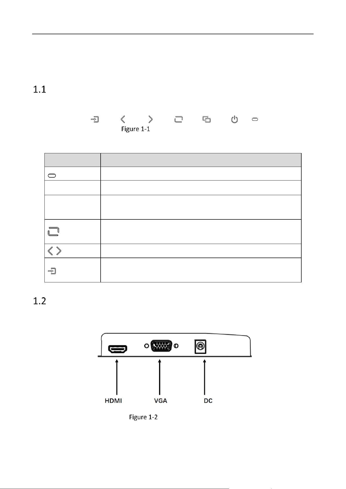
Buttons on the Front Panel
Buttons on the front panel of the device are shown as follows.
Buttons on the Front Panel
Tablet 1-1 Button Description
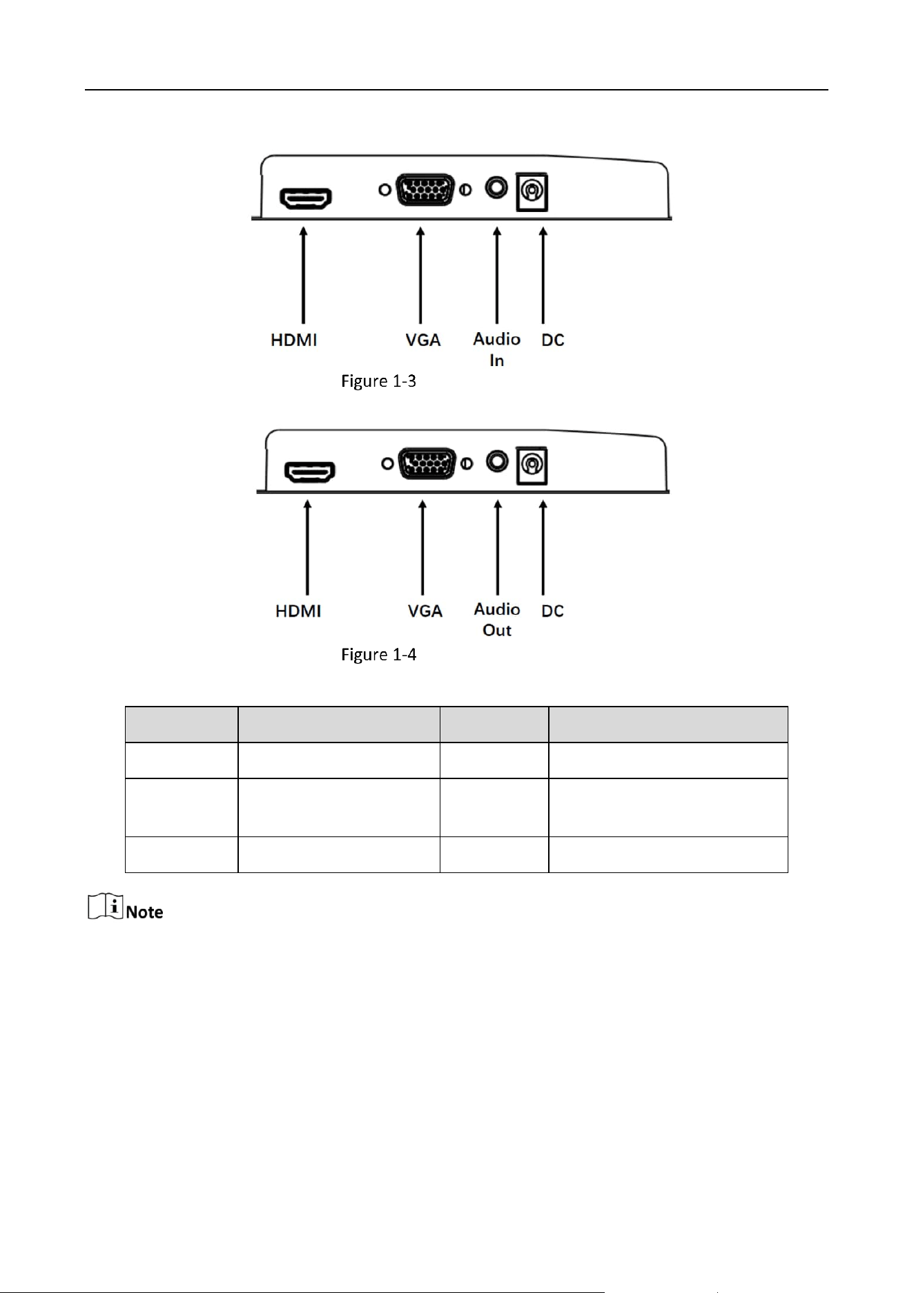
Interfaces on the Rear Panel
The interfaces that may be found on the rear panel of the device are defined as follows.
Rear Interface Type 1
Button
Description
Power Supply Indicator
Turn On/Off
MENU and Signal Source page: Exit MENU and Signal Source page.
Other pages: Show MENU page.
Show the current signal source
Other pages: Confirm
MENU secondary page: Add or Decrease the value
Show all signal sources on screen.
Other pages: Switch to the next page.
Monitor • User Manual
2
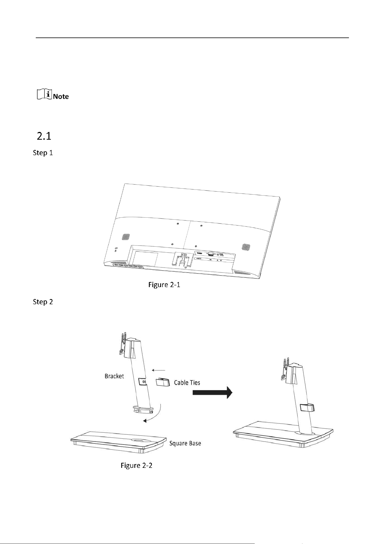
Rear Interface Type 2
Rear Interface Type 3
Table 1-2 Interface Description
The device supports power adapter to power on.
The figures are for reference only. The actual device prevails.
Interface
Description
Interface
Description
HDMI
HDMI digital signal input
VGA
VGA analog signal input
Audio In
3.5 mm Audio input
interface
Audio Out
3.5 mm Audio output
interface
DC
Power input interface
Monitor • User Manual
3
Chapter 2 Installation and Power On
The installation drawings are for reference only.
Install the Square Base
Gently lift the device. Place the screen down on a stable surface covered with a thick soft
cloth so that the bottom of the device is close to the edge of the surface for mounting the
bracket.
Place the Monitor
Take out the bracket, cable ties, and square base from the packing box. Align the cable ties
with the holes in the bracket and insert the cable ties into the bracket. Then align the
bracket with the buckle on the base and fix the bracket clockwise.
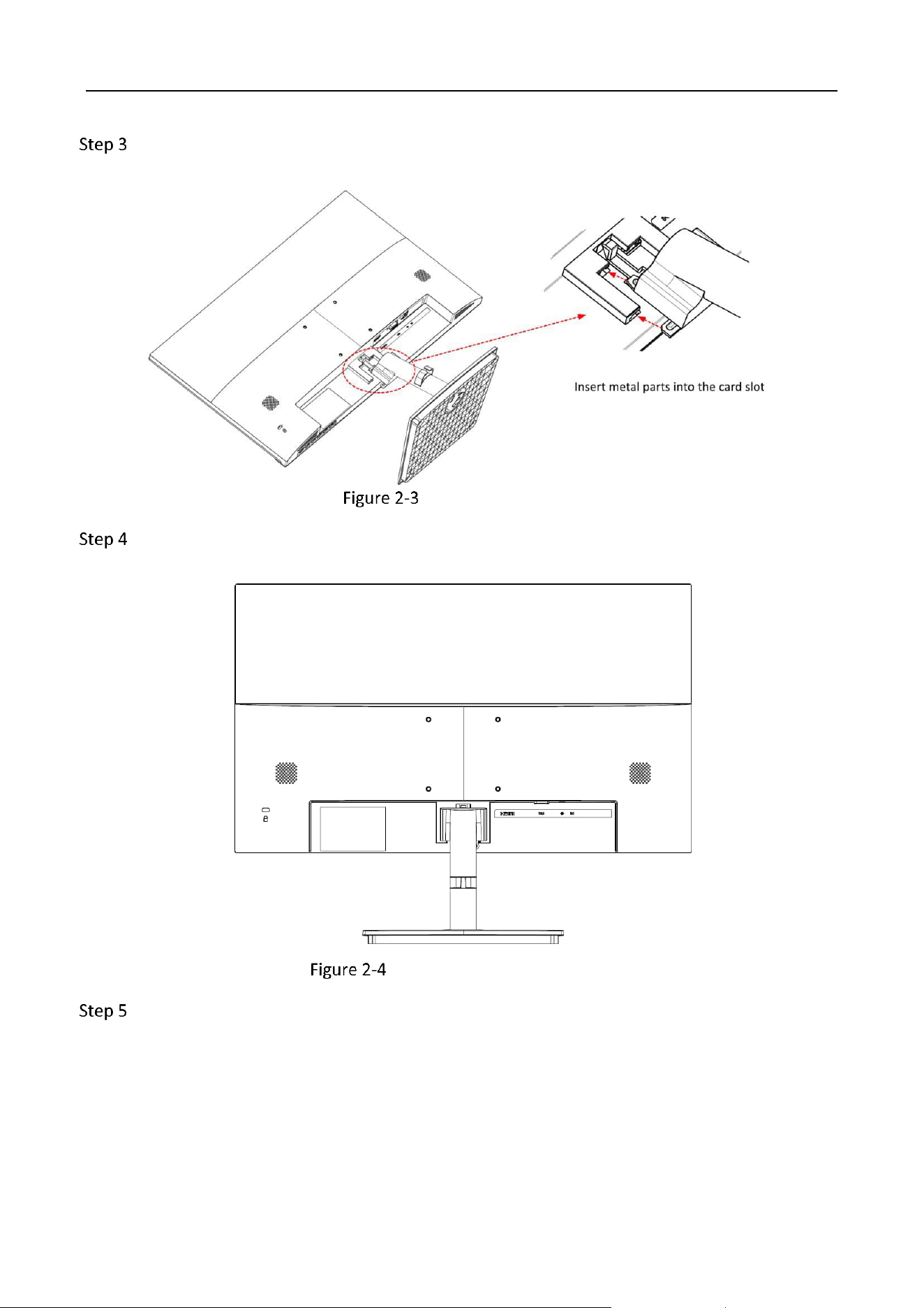
Fix the Bracket with the Square Base
Monitor • User Manual
4
Align the metal parts on the bracket of square base with the slots at the back of the device
and insert them.
Insert the Metal Parts
Installation finished.
Fix the Bracket with the Device
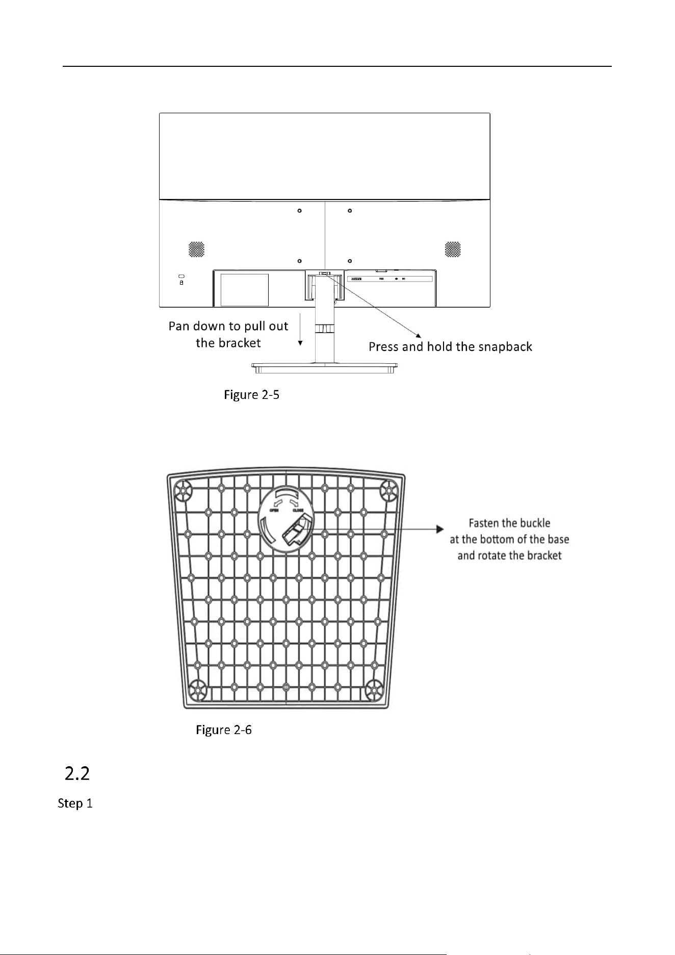
(Optional) To remove the square base, perform the following operations.
1) Press and hold the snapback on the back of the device, pan down and pull out the
bracket.
Monitor • User Manual
5
Remove the Device and Bracket
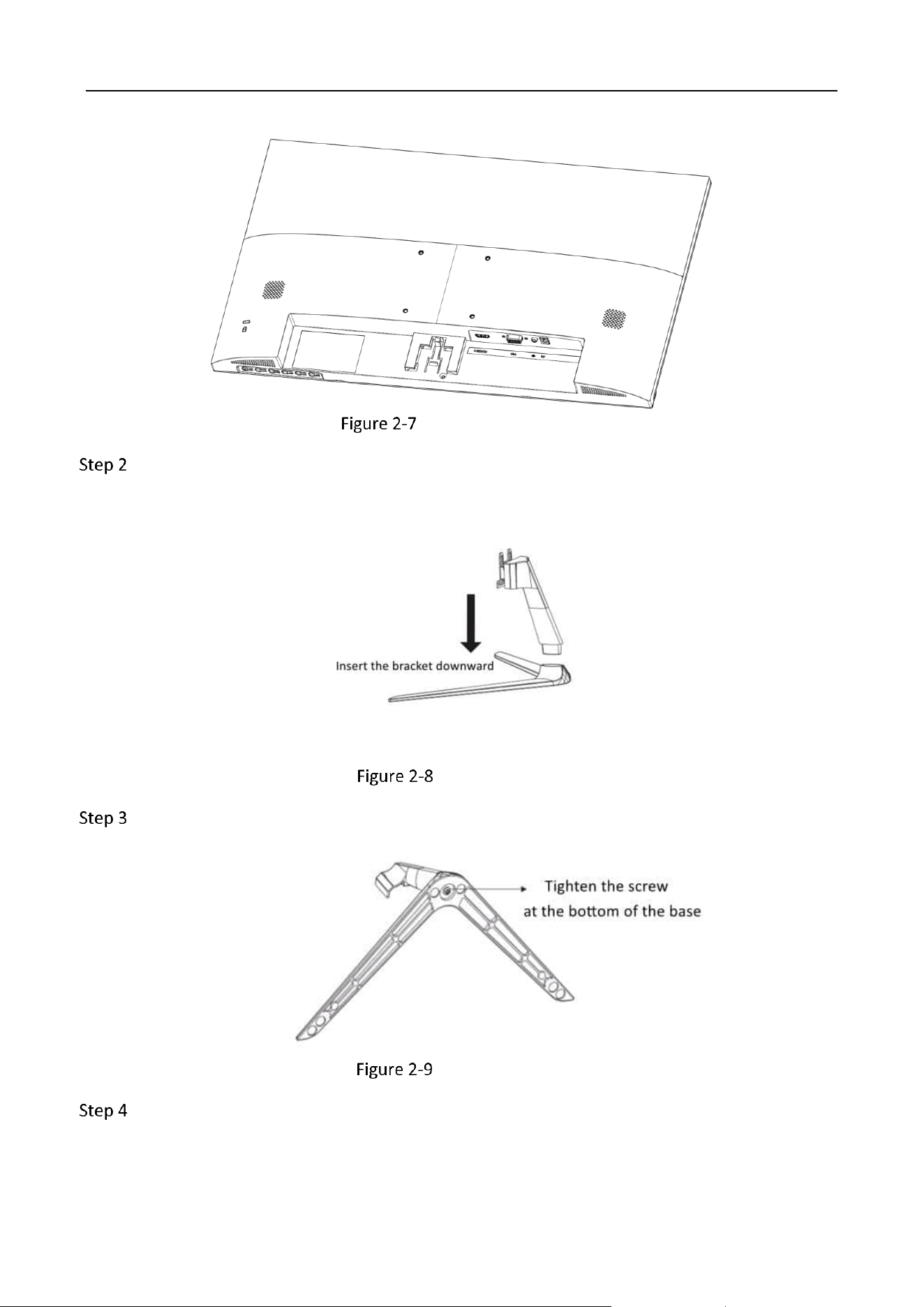
2) Fasten the buckle at the bottom of the base with your finger, and rotate the bracket in
the direction indicated by OPEN to remove it from the square base.
Remove the Bracket from the Square Base
Install the Herringbone Base
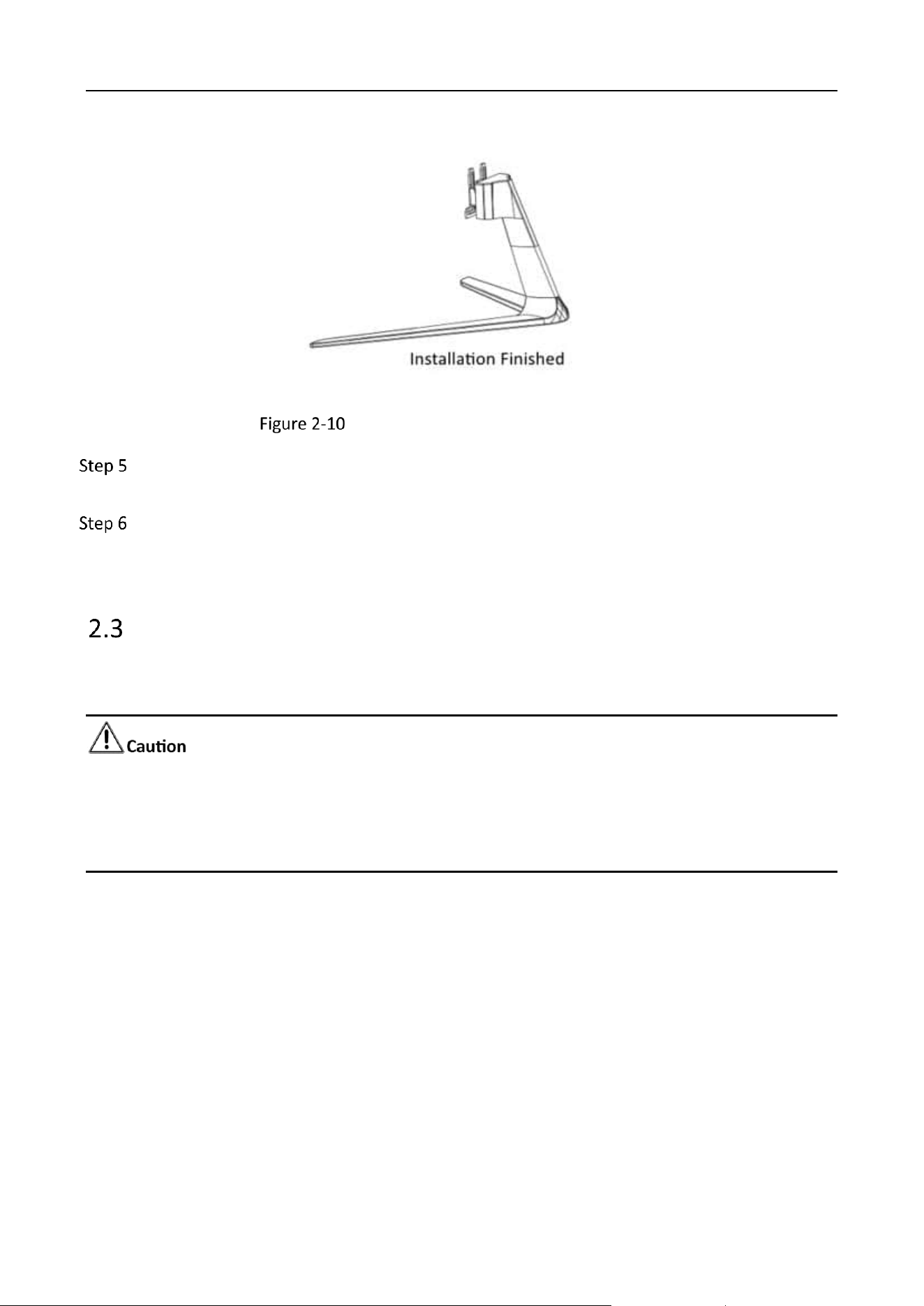
Gently lift the device and place the screen down on a stable surface covered with a thick soft
cloth so that the bottom of the device is close to the edge of the surface for mounting the
bracket.
Monitor • User Manual
6
Place the Device Flatly
Take out the bracket and the herringbone base from the packing box, and insert the bracket
downward into the grooves of the herringbone base.
Install the Bracket
Tighten the screw at the bottom of the base to secure the bracket to the base.
Tighten the Screw
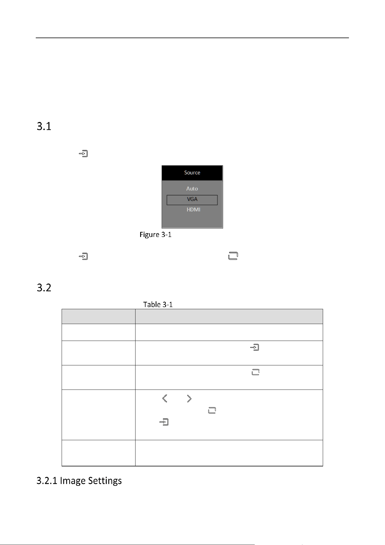
Install the bracket on the herringbone base.
Monitor • User Manual
7
Install the Bracket on the Herringbone Base
Fix the bracket with the device. For details about how to secure a square base, see 2.1 Step
3.
If the herringbone base needs to be removed, remove the bracket and device in the same
way as the square base. For details, see 2.1 Step 5. When removing the bracket and base,
loosen the screws at the bottom of the herringbone base and lift out the bracket.
Power On the Device
After connecting the adapter, plug the device into a well-grounded bar and turn on the switch to
power on.
Power supply: DC 12 V, 2 A.
If you do not use the device for a long time, turn off the display switch and remove the power
plug from the power socket.
Monitor • User Manual
8
Chapter 3 Basic Operations
The user interface may vary depending on the device model. The following image is used as an
example.
Select the Signal Source
Connect the power cable and confirm that there is a video signal input, turn on the display.
Step 1 Press and show the signal source menu.
Select the Signal Source
Step 2 Press again to select the signal source and press to confirm.
Main Menu
Operation Description
Operation
Description
Enter MENU page
Press to enter the main menu page.
View the first-level
MENU
On the main menu page, press to switch to the
different first-level menu.
View Parameters
On the first-level menu page, press to enter the right-
side parameters page.
Adjust Parameters
Press or to adjust the value of the current
parameter and press to confirm.
Press to switch to other parameters on the current
page.
Back to the upper-
level menu
Press to return to the upper-level menu on any
page.
Monitor • User Manual
9
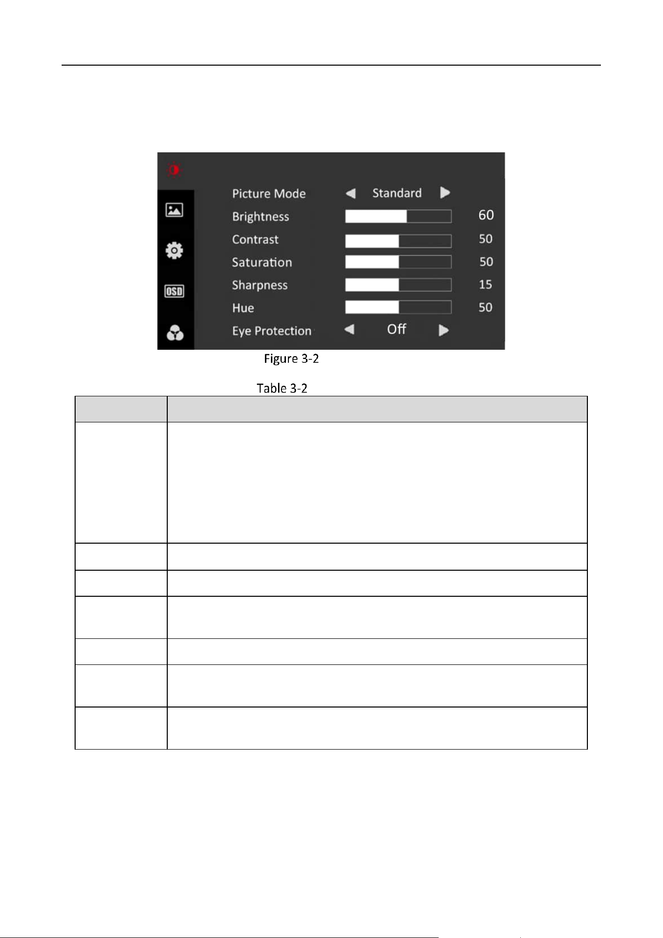
You can switch picture modes and adjust image parameters including contrast, brightness,
saturation, sharpness, and hue. The adjustable parameters will change when you switch picture
modes.
Image Settings
Image Parameters
Parameter
Description
Picture Mode
Standard: Suitable for a normal environment. It is the default picture
mode.
Soft: Suitable for a dark room.
Dynamic: Suitable for a bright room.
User: Customize the brightness, contrast, color, sharpness or hue to adjust
display effect.
Brightness
Ranges from 0 to 100. The higher the value is, the brighter the image will be.
Contrast
Ranges from 0 to 100. The higher the value is, the clearer the image will be
Saturation
Ranges from 0 to 100. The higher the value is, the more colorful the image
will be.
Sharpness
Ranges from 0 to 30. Rise the value up to make the image more vivid.
Hue
Ranges from 0 to 100. It determines the contrast degree between the bright
and dark.
Eye Protection
Off/Weak/Medium/Strong. It can effectively reduce blue light radiation,
alleviate eye fatigue, and protect vision.
Monitor • User Manual
10
Under other modes, only brightness and contrast are adjustable.
Parameters in white bar are adjustable. If the parameter bar is gray, it indicates that the
parameter is not adjustable under the current mode or input source.
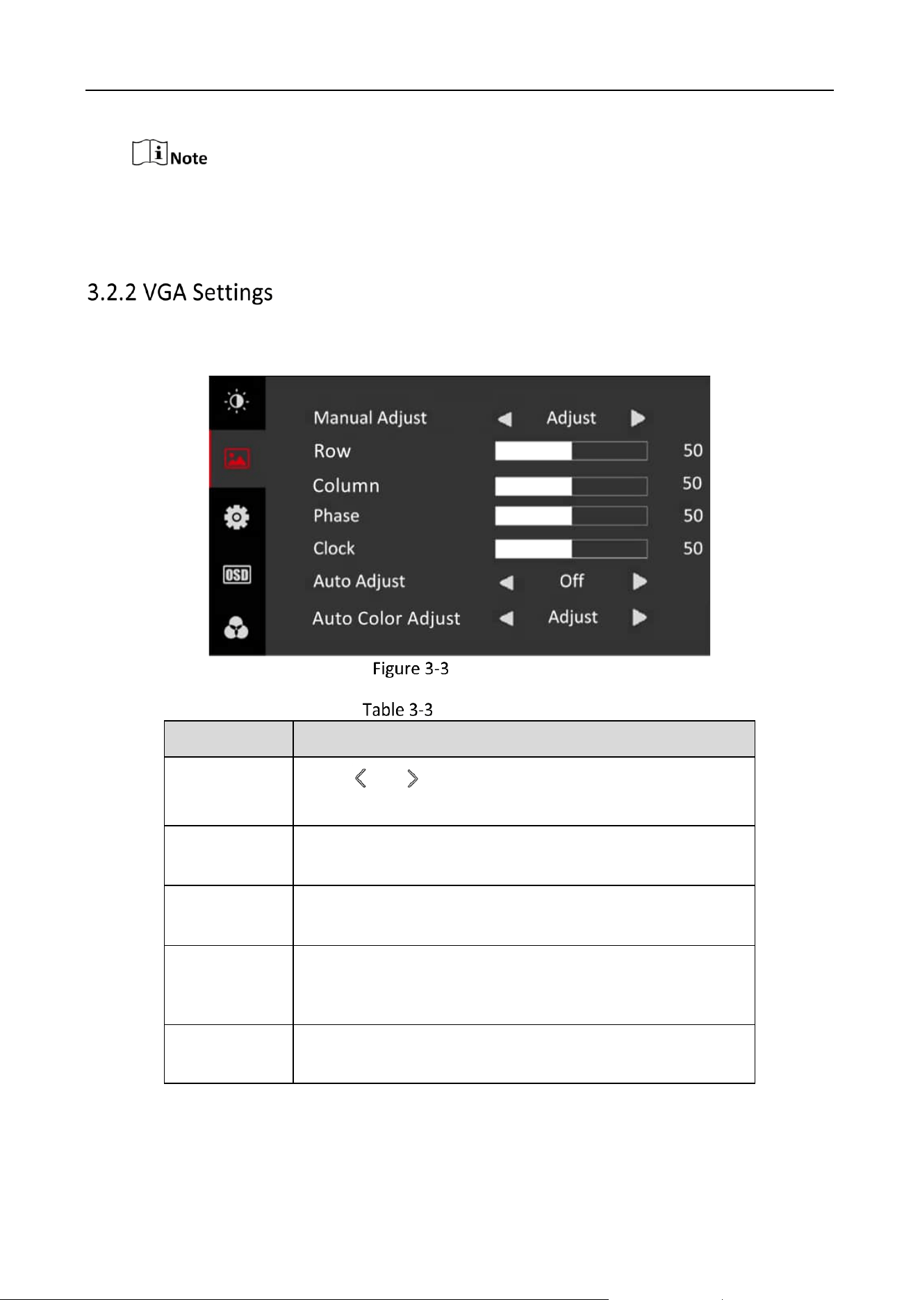
When you select VGA as the input source, you can adjust VGA parameters to make the picture
shown in the correct position.
VGA Settings
VGA Parameters
Parameter
Description
Manual Adjust
Press or to enable or disable. Adjust the size and
position of the image.
Row
Ranges from 0 to 100. Move the image position to the left
or right.
Column
Ranges from 0 to 100. Move the image position to the top
or bottom.
Phase
Ranges from 0 to 100. Adjust the value of Phase to change
the image position in a slight extent at the horizontal level.
Clock
Ranges from 0 to 100. Change the value of Clock to stretch
or narrow the image.
Monitor • User Manual
11
Parameter
Description
Auto Adjust
Off/On. If Auto Adjust is enabled, the related parameters
will self-adjust under the following 3 circumstances. The
device is restarted, a VGA input source is accessed, and the
input source is switched to VGA. VGA parameters cannot be
changed when Auto Adjust is disabled.
Auto Color
Adjust
Adjust/Off. When Auto Color Adjsut is enabled, the level
change of analog signal will be readjusted to ensure the
best display effect of the image.
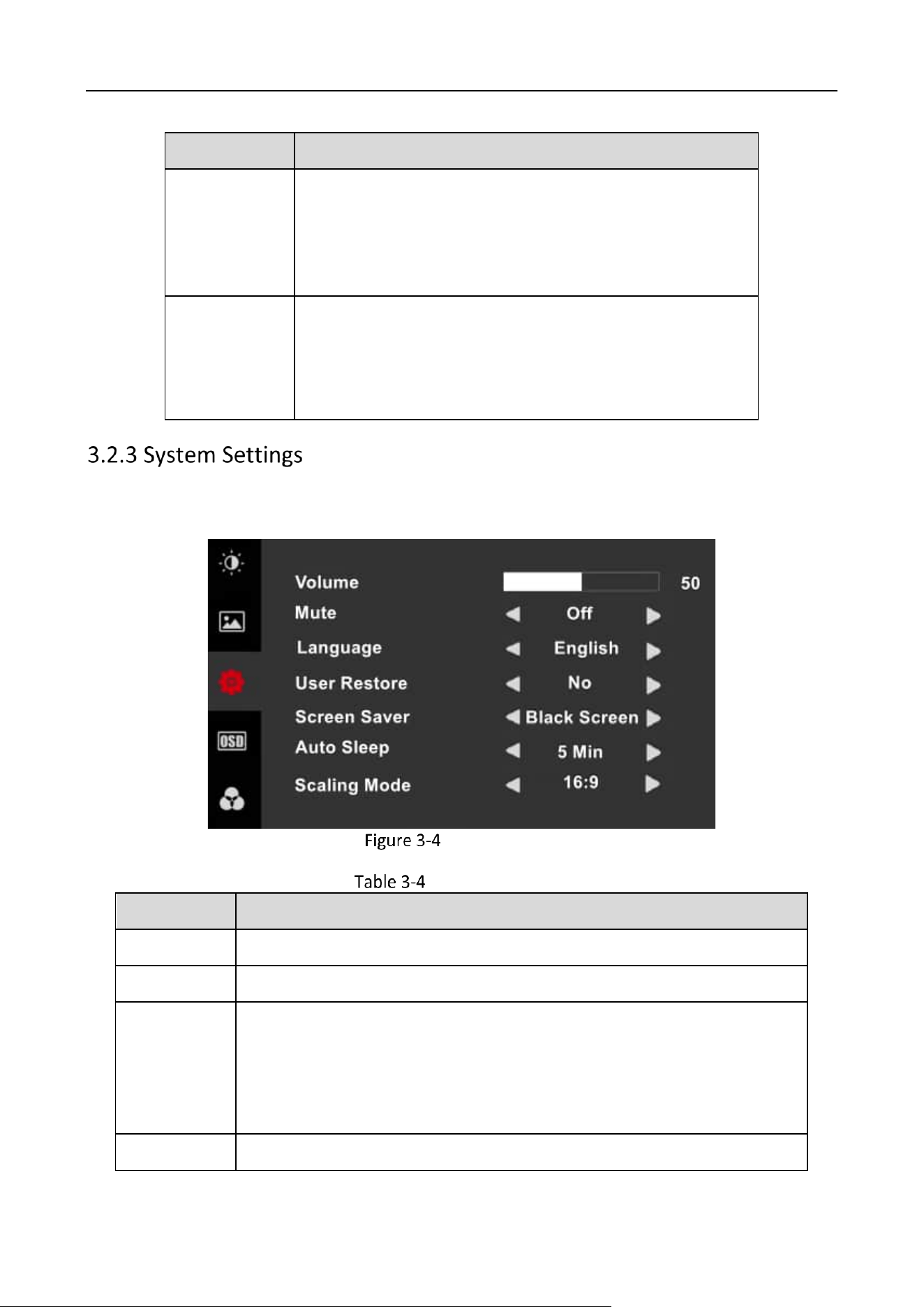
You can change the settings of language, screen saver, volume, and other parameters on the
system settings page. Volume settings is only available to part of the product models.
System Settings
System Parameters
Parameter
Description
Volume
Ranges from 0 to 100. Adjust the volume of the monitor.
Mute
OFF/ON
Language
中文/English/Русский/Deutsch/Italiano/Français/
Nederlands/Português/Español/Tiếng Việt/
Български/Magyar/Ελληνικά/Čeština/Slovenčina/
Polski/Română/Dansk/Svenska/Norsk/Suomi/Hrvatski/Srpski
User Restore
No/Yes. Restore default settings except Language.
Monitor • User Manual
12
Parameter
Description
Screen Saver
Black Screen/Blue Screen. The background color of the screen when there
is no signal.
Auto Sleep
Off/30 S/1 Min/5 Min/10 Min/30 Min/1 H
Scaling Mode
16:9/4:3. Adjust the image scale: the ratio between the width and height
of the image.
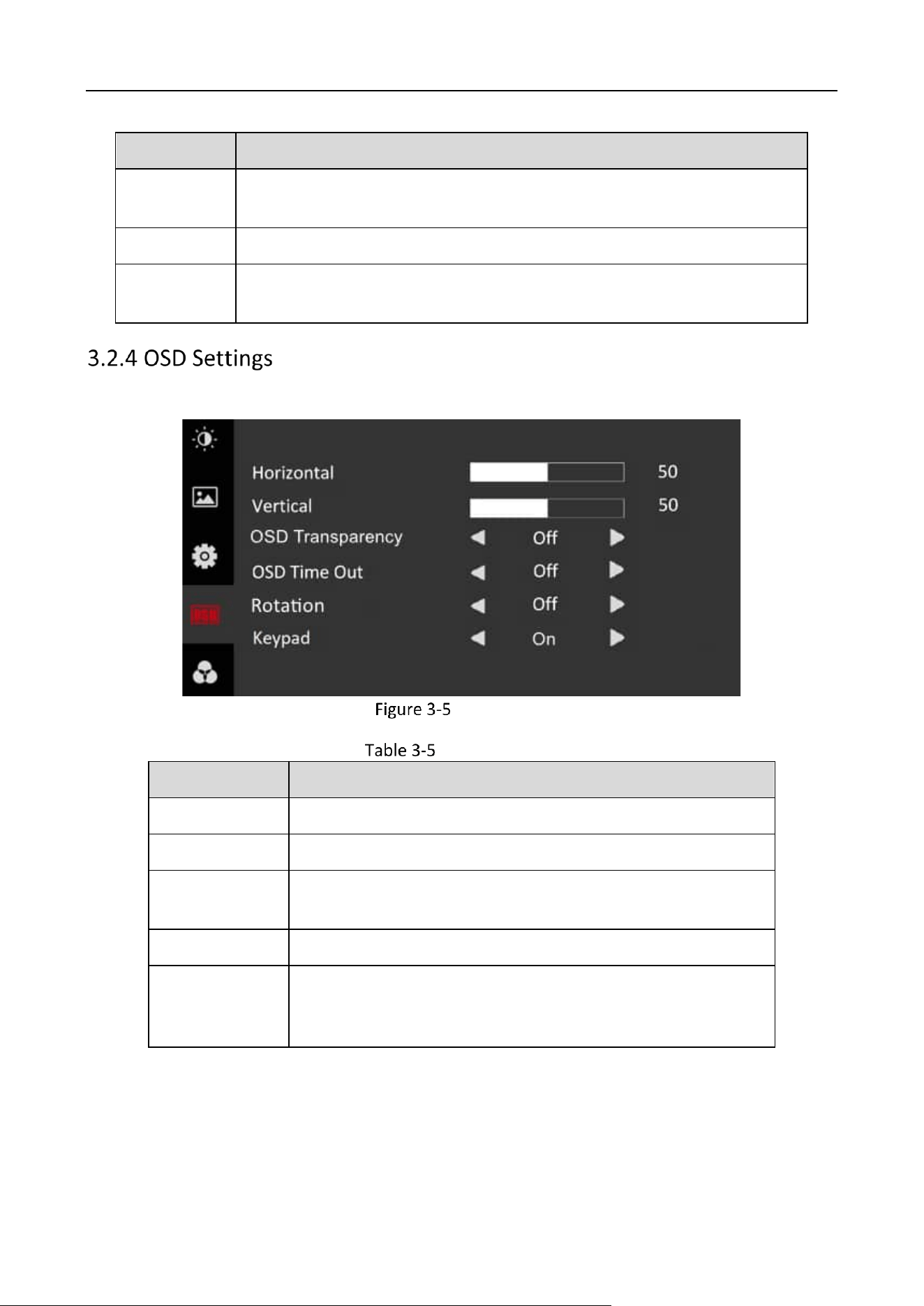
OSD parameters concern the display effect of OSD, such as position, transparency, and rotation.
OSD Settings
OSD Parameters
Parameter
Description
Horizontal
Ranges from 0 to 100. Adjust the OSD at the horizontal level.
Vertical
Ranges from 0 to 100. Adjust the OSD at the vertical level.
OSD
Transparency
Off/Weak/Medium/Strong. Adjust the transparent degree of
the OSD.
OSD Time Out
Off/5 S/15 S/30 S/1 Min
Rotation
Off/On. If Rotation is enabled, the OSD will rotate 270 degrees
clockwise, and the point (0, 0) represents the original point and
is at the bottom-left corner.
Monitor • User Manual
13
Parameter
Description
Keypad
Set to On by default. If set to Off, OSD will change within 5
seconds. If there is no operation within 5 seconds, the system
will exit OSD mode and you can press any button to see
unlocking prompt. You can follow the prompt and hold Menu
to unlock.
Software Version

UD38627B