
DS-K281X Series Access Controller
User Manual

Legal Informaon
©2022 Hangzhou Hikvision Digital Technology Co., Ltd. All rights reserved.
About this Manual
The Manual includes instrucons for using and managing the Product. Pictures, charts, images and
all other informaon hereinaer are for descripon and explanaon only. The informaon
contained in the Manual is subject to change, without noce, due to rmware updates or other
reasons. Please nd the latest version of this Manual at the Hikvision website ( hps://
www.hikvision.com/ ).
Please use this Manual with the guidance and assistance of professionals trained in
supporng the
Product.
Trademarks
and other Hikvision's trademarks and logos are the properes of
Hikvision in various jurisdicons.
Other trademarks and logos menoned are the properes of their respecve owners.
Disclaimer
TO THE MAXIMUM EXTENT PERMITTED BY APPLICABLE LAW, THIS MANUAL AND THE PRODUCT
DESCRIBED, WITH ITS HARDWARE, SOFTWARE AND FIRMWARE, ARE PROVIDED "AS IS" AND "WITH
ALL FAULTS AND ERRORS". HIKVISION MAKES NO WARRANTIES, EXPRESS OR IMPLIED, INCLUDING
WITHOUT LIMITATION, MERCHANTABILITY, SATISFACTORY QUALITY, OR FITNESS FOR A PARTICULAR
PURPOSE. THE USE OF THE PRODUCT BY YOU IS AT YOUR OWN RISK. IN NO EVENT WILL HIKVISION
BE LIABLE TO YOU FOR ANY SPECIAL, CONSEQUENTIAL, INCIDENTAL, OR INDIRECT DAMAGES,
INCLUDING, AMONG OTHERS, DAMAGES FOR LOSS OF BUSINESS PROFITS, BUSINESS
INTERRUPTION, OR LOSS OF DATA, CORRUPTION OF SYSTEMS, OR LOSS OF DOCUMENTATION,
WHETHER BASED ON BREACH OF CONTRACT, TORT (INCLUDING NEGLIGENCE), PRODUCT LIABILITY,
OR OTHERWISE, IN CONNECTION WITH THE USE OF THE PRODUCT, EVEN IF HIKVISION HAS BEEN
ADVISED OF THE POSSIBILITY OF SUCH DAMAGES OR LOSS.
YOU ACKNOWLEDGE THAT THE NATURE OF THE INTERNET PROVIDES FOR INHERENT SECURITY
RISKS, AND HIKVISION SHALL NOT TAKE ANY RESPONSIBILITIES FOR ABNORMAL OPERATION,
PRIVACY LEAKAGE OR OTHER DAMAGES RESULTING FROM CYBER-ATTACK, HACKER ATTACK, VIRUS
INFECTION, OR OTHER INTERNET SECURITY RISKS; HOWEVER, HIKVISION WILL PROVIDE TIMELY
TECHNICAL SUPPORT IF REQUIRED.
YOU AGREE TO USE THIS PRODUCT IN COMPLIANCE WITH ALL APPLICABLE LAWS, AND YOU ARE
SOLELY RESPONSIBLE FOR ENSURING THAT YOUR USE CONFORMS TO THE APPLICABLE LAW.
ESPECIALLY, YOU ARE RESPONSIBLE, FOR USING THIS PRODUCT IN A MANNER THAT DOES NOT
INFRINGE ON THE RIGHTS OF THIRD PARTIES, INCLUDING WITHOUT LIMITATION, RIGHTS OF
PUBLICITY, INTELLECTUAL PROPERTY RIGHTS, OR DATA PROTECTION AND OTHER PRIVACY RIGHTS.
YOU SHALL NOT USE THIS PRODUCT FOR ANY PROHIBITED END-USES, INCLUDING THE
DS-K281X Series Access Controller User Manual
i

DEVELOPMENT OR PRODUCTION OF WEAPONS OF MASS DESTRUCTION, THE DEVELOPMENT OR
PRODUCTION OF CHEMICAL OR BIOLOGICAL WEAPONS, ANY ACTIVITIES IN THE CONTEXT RELATED
TO ANY NUCLEAR EXPLOSIVE OR UNSAFE NUCLEAR FUEL-CYCLE, OR IN SUPPORT OF HUMAN
RIGHTS ABUSES.
IN THE EVENT OF ANY CONFLICTS BETWEEN THIS MANUAL AND THE APPLICABLE LAW, THE LATTER
PREVAILS.
DS-K281X Series Access Controller User Manual
ii

Available Model
Product Name Model
Access Controller DS-K2811
DS-K2812
DS-K2814
DS-K281X Series Access Controller User Manual
iii

Regulatory Informaon
FCC Informaon
Please take aenon that changes or modicaon not expressly approved by the party responsible
for compliance could void the user’s authority to operate the equipment.
FCC compliance: This equipment has been tested and found to comply with the limits for a Class B
digital device, pursuant to part 15 of the FCC Rules. These limits are designed to provide
reasonable
protecon against harmful interference in a residenal installaon. This equipment
generates, uses and can radiate radio frequency energy and, if not installed and used in accordance
with the
instrucons, may cause harmful interference to radio communicaons. However, there is
no guarantee that interference will not occur in a parcular installaon. If this equipment does
cause harmful interference to radio or television
recepon, which can be determined by turning
the equipment o and on, the user is encouraged to try to correct the interference by one or more
of the following measures:
—Reorient or relocate the receiving antenna.
—Increase the
separaon between the equipment and receiver.
—Connect the equipment into an outlet on a circuit
dierent from that to which the receiver is
connected.
—Consult the dealer or an experienced radio/TV technician for help
This equipment should be installed and operated with a minimum distance 20cm between the
radiator and your body.
FCC
Condions
This device complies with part 15 of the FCC Rules. Operaon is subject to the following two
condions:
1. This device may not cause harmful interference.
2. This device must accept any interference received, including interference that may cause
undesired
operaon.
EU Conformity Statement
This product and - if applicable - the supplied accessories too are marked with "CE"
and comply therefore with the applicable harmonized European standards listed
DS-K281X Series Access Controller User Manual
iv

under the EMC Direcve 2014/30/EU, RE Direcve 2014/53/EU,the RoHS Direcve
2011/65/EU
2012/19/EU (WEEE direcve): Products marked with this symbol cannot be disposed
of as unsorted municipal waste in the European Union. For proper recycling, return
this product to your local supplier upon the purchase of equivalent new equipment,
or dispose of it at designated
collecon points. For more informaon see:
www.recyclethis.info
2006/66/EC (baery direcve): This product contains a baery that cannot be
disposed of as unsorted municipal waste in the European Union. See the product
documentaon for specic baery informaon. The baery is marked with this
symbol, which may include
leering to indicate cadmium (Cd), lead (Pb), or mercury
(Hg). For proper recycling, return the
baery to your supplier or to a designated
collecon point. For more informaon see:www.recyclethis.info
Industry Canada ICES-003 Compliance
This device meets the CAN ICES-3 (B)/NMB-3(B) standards requirements.
This device complies with Industry Canada licence-exempt RSS standard(s). Operaon is subject to
the following two
condions:
1. this device may not cause interference, and
2. this device must accept any interference, including interference that may cause undesired
operaon of the device.
Le présent appareil est conforme aux CNR d'Industrie Canada applicables aux appareils
radioexempts de licence.
L'exploitaon est autorisée aux deux condions suivantes :
1. l'appareil ne doit pas produire de brouillage, et
2.
l'ulisateur de l'appareil doit accepter tout brouillage radioélectrique subi, même si le brouillage
est suscepble d'en compromere le fonconnement.
Under Industry Canada regulaons, this radio transmier may only operate using an antenna of a
type and maximum (or lesser) gain approved for the transmier by Industry Canada. To reduce
potenal radio interference to other users, the antenna type and its gain should be so chosen that
the equivalent isotropically radiated power (e.i.r.p.) is not more than that necessary for successful
communicaon.
Conformément à la réglementaon d'Industrie Canada, le présent émeeur radio peut fonconner
avec une antenne d'un type et d'un gain maximal (ou inférieur) approuvé pour l'émeeur par
Industrie Canada. Dans le but de réduire les risques de brouillage radioélectrique à l'intenon des
autres ulisateurs, il faut choisir le type d'antenne et son gain de sorte que la puissance isotrope
rayonnée équivalente (p.i.r.e.) ne dépasse pas l'intensité nécessaire à l'établissement d'une
communicaon sasfaisante.
This equipment should be installed and operated with a minimum distance 20cm between the
radiator and your body.
DS-K281X Series Access Controller User Manual
v

Cet équipement doit être installé et ulisé à une distance minimale de 20 cm entre le radiateur et
votre corps.
DS-K281X Series Access Controller User Manual
vi
Safety Instrucon
These instrucons are intended to ensure that user can use the product correctly to avoid danger
or property loss.
The
precauon measure is divided into Dangers and Cauons:
Dangers: Neglecng any of the warnings may cause serious injury or death.
Cauons: Neglecng any of the cauons may cause injury or equipment damage.
Dangers: Follow these safeguards to prevent
serious injury or death.
Cauons: Follow these precauons to prevent
potenal injury or material damage.
Danger:
●
All the electronic operaon should be strictly compliance with the electrical safety regulaons,
re prevenon regulaons and other related regulaons in your local region.
●
Please use the power adapter, which is provided by normal company. The power consumpon
cannot be less than the required value.
●
Do not connect several devices to one power adapter as adapter overload may cause over-heat
or
re hazard.
●
Please make sure that the power has been disconnected before you wire, install or dismantle the
device.
●
When the product is installed on wall or ceiling, the device shall be
rmly xed.
●
If smoke, odors or noise rise from the device, turn
o the power at once and unplug the power
cable, and then please contact the service center.
●
Do not ingest baery, Chemical Burn Hazard.
This product contains a
coin/buon cell baery. If the coin/buon cell baery is swallowed, it
can cause severe internal burns in just 2 hours and can lead to death.
Keep new and used
baeries away from children. If the baery compartment does not close
securely, stop using the product and keep it away from children. If you think baeries might have
been swallowed or placed inside any part of the body, seek immediate medical
aenon.
●
If the product does not work properly, please contact your dealer or the nearest service center.
Never
aempt to disassemble the device yourself. (We shall not assume any responsibility for
problems caused by unauthorized repair or maintenance.)
DS-K281X Series Access Controller User Manual
vii

Cauons:
●
Do not drop the device or subject it to physical shock, and do not expose it to high
electromagnesm radiaon. Avoid the equipment installaon on vibraons surface or places
subject to shock (ignorance can cause equipment damage).
●
Do not place the device in extremely hot (refer to the specicaon of the device for the detailed
operang temperature), cold, dusty or damp locaons, and do not expose it to high
electromagnec radiaon.
●
The device cover for indoor use shall be kept from rain and moisture.
●
Exposing the equipment to direct sun light, low venlaon or heat source such as heater or
radiator is forbidden (ignorance can cause re danger).
●
Do not aim the device at the sun or extra bright places. A blooming or smear may occur
otherwise (which is not a malfuncon however), and aecng the endurance of sensor at the
same me.
●
Please use the provided glove when open up the device cover, avoid direct contact with the
device cover, because the acidic sweat of the ngers may erode the surface coang of the device
cover.
●
Please use a so and dry cloth when clean inside and outside surfaces of the device cover, do
not use alkaline detergents.
●
Please keep all wrappers
aer unpack them for future use. In case of any failure occurred, you
need to return the device to the factory with the original wrapper. Transportaon without the
original wrapper may result in damage on the device and lead to addional costs.
●
Improper use or replacement of the
baery may result in hazard of explosion. Replace with the
same or equivalent type only. Dispose of used baeries according to the instrucons provided by
the
baery manufacturer.
DS-K281X Series Access Controller User Manual
viii

Contents
Chapter 1 Prevenve and Cauonary Tips .................................................................................. 1
Chapter 2 Product Descripon .................................................................................................... 2
Chapter 3 Main Board Descripon .............................................................................................. 3
3.1 Single-Door Access Controller Main Board Descripon ......................................................... 3
3.2 Two-Door Access Controller Main Board Descripon ............................................................ 4
3.2.1 Four-Door Access Controller Main Board Descripon .................................................. 5
3.3 Component Descripon ......................................................................................................... 5
3.4 Baery Charging Board .......................................................................................................... 7
Chapter 4 Terminal
Descripon .................................................................................................. 8
4.1 Single-Door Access Controller Terminal Descripon .............................................................. 8
4.2 Two-Door Access Controller Terminal Descripon ............................................................... 10
4.3 Four-Door Access Controller Terminal
Descripon .............................................................. 13
Chapter 5 Installaon ............................................................................................................... 17
5.1 Wall Mounng ..................................................................................................................... 17
Chapter 6 Terminal Wiring ........................................................................................................ 19
6.1 Main Board Wiring ............................................................................................................... 19
6.2 Wiegand Card Reader Wiring ............................................................................................... 20
6.3 RS-485 Card Reader Wiring .................................................................................................. 20
6.4 Cathode Lock Wiring ............................................................................................................ 21
6.5 Anode Lock Wiring ............................................................................................................... 22
6.6 Alarm Output Wiring ........................................................................................................... 23
6.7 Exit
Buon Wiring ................................................................................................................ 23
6.8 Door Contact Wiring ............................................................................................................ 24
6.9 Power Supply Wiring ............................................................................................................ 24
Chapter 7
Sengs .................................................................................................................... 26
7.1 Inializaon (Opon 1) ........................................................................................................ 26
DS-K281X Series Access Controller User Manual
ix

7.2 Inializaon (Opon 2) ........................................................................................................ 26
7.3 Relay Output NO/NC Sengs .............................................................................................. 27
7.3.1 Lock Relay Output
Sengs ......................................................................................... 27
7.3.2 Alarm Relay Output Sengs ....................................................................................... 28
Chapter 8 Acvaon ................................................................................................................. 30
8.1 Acvate via SADP ................................................................................................................. 30
8.2 Acvate Device via Client Soware ...................................................................................... 31
Chapter 9 Client Soware Conguraon ................................................................................... 33
9.1 Conguraon Flow of Client Soware ................................................................................. 33
9.2 Device Management ............................................................................................................ 34
9.2.1 Add Device .................................................................................................................. 34
9.2.2 Reset Device Password ................................................................................................ 37
9.2.3 Manage Added Devices .............................................................................................. 38
9.3 Group Management ............................................................................................................. 39
9.3.1 Add Group ................................................................................................................... 39
9.3.2 Import Resources to Group ......................................................................................... 40
9.4 Person Management ............................................................................................................ 40
9.4.1 Add
Organizaon ........................................................................................................ 40
9.4.2 Import and Export Person Idenfy Informaon .......................................................... 41
9.4.3 Get Person
Informaon from Access Control Device .................................................. 43
9.4.4 Issue Cards to Persons in Batch ................................................................................... 44
9.4.5 Report Card Loss ......................................................................................................... 45
9.4.6 Set Card Issuing Parameters ........................................................................................ 45
9.5
Congure Schedule and Template ....................................................................................... 46
9.5.1 Add Holiday ................................................................................................................. 46
9.5.2 Add Template .............................................................................................................. 47
9.6 Set Access Group to Assign Access
Authorizaon to Persons .............................................. 49
9.7
Congure Advanced Funcons ............................................................................................ 50
DS-K281X Series Access Controller User Manual
x

9.7.1 Congure Remaining Unlocked/Locked ...................................................................... 50
9.7.2 Congure An-Passback ............................................................................................. 51
9.7.3
Congure Mul-door Interlocking .............................................................................. 52
9.7.4 Congure First Person In ............................................................................................. 53
9.7.5 Congure Mul-Factor Authencaon ....................................................................... 54
9.7.6 Congure Card Reader Authencaon Mode and Schedule ...................................... 56
9.7.7 Congure Device Parameters ...................................................................................... 58
9.7.8 Congure Device Parameters ...................................................................................... 62
9.8 Door Control ........................................................................................................................ 63
9.8.1 Control Door Status ..................................................................................................... 63
9.8.2 Check Real-Time Access Records ................................................................................ 64
Appendix A. Tips for Scanning Fingerprint ................................................................................ 65
Appendix B. DIP Switch
Descripon .......................................................................................... 67
Appendix C. Custom Wiegand Rule
Descripons ....................................................................... 68
Appendix D. Communicaon Matrix and Device Command ...................................................... 70
DS-K281X Series Access Controller User Manual
xi
Chapter 1 Prevenve and Cauonary Tips
Before connecng and operang your device, please be advised of the following ps:
●
Ensure unit is installed in a well-venlated, dust-free environment.
●
Keep all liquids away from the device.
●
Ensure environmental
condions meet factory specicaons.
●
Ensure unit is properly secured to a rack or shelf. Major shocks or jolts to the unit as a result of
dropping it may cause damage to the sensive electronics within the unit.
●
Use the device in conjuncon with an UPS if possible.
●
Power down the unit before
connecng and disconnecng accessories and peripherals.
●
A factory recommended HDD should be used for this device.
●
Improper use or replacement of the
baery may result in hazard of explosion. Replace with the
same or equivalent type only. Dispose of used baeries according to the instrucons provided by
the manufacturer.
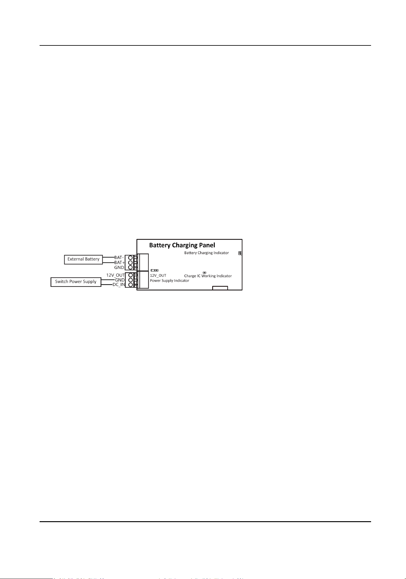
●
It is recommended to choose a 12 V 7 AH lead-acid baery that meets the IEC 60896 standard.
The baery wiring method is shown in the following gure.
DS-K281X Series Access Controller User Manual
1

Chapter 2 Product Descripon
●
32-bit high-speed processor
●
Supports TCP/IP communicaon. The communicaon data is specially encrypted to relieve the
concern of privacy leak
●
Supports
recognion and storage of card No. with maximum length of 20
●
Supports up to 10,000 cards and 50,000 card presenng records
●
Supports
mul-door interlock funcon, inner-device an-passback funcon, mulple
authencaons
funcon, open door with rst card funcon, super password funcon, M1 card
encrypon, online upgrade funcon and remote control of the doors
●
IP address
conict detecon
●
Supports RS-485 interface and Wiegand interface for accessing card reader. Wiegand interface
supports W26, W34 and is compable with the third-party card reader with Wiegand interface
●
Various indicators to show dierent status
●
Supports record storage
funcon when the device is oine and insucient storage space
storage alarm funcon
●
Data can be permanently saved aer the access controller is powered o
●
Supports I/O linkage and event linkage
DS-K281X Series Access Controller User Manual
2
Chapter 3 Main Board Descripon
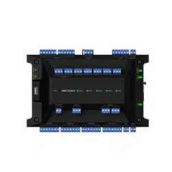
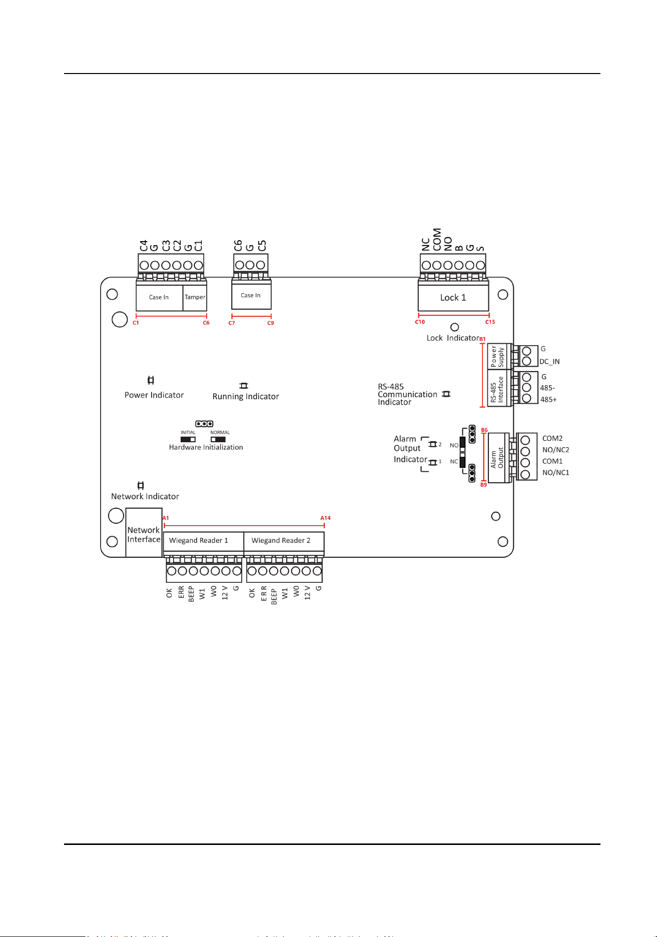
3.1 Single-Door Access Controller Main Board Descripon
Figure 3-1 Single-Door Access Controller Main Board
DS-K281X Series Access Controller User Manual
3
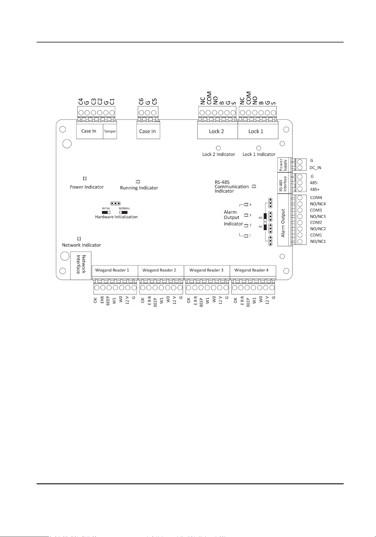
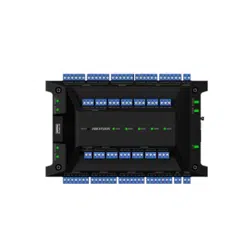
3.2 Two-Door Access Controller Main Board Descripon
Figure 3-2 Two-Door Access Controller Main Board
DS-K281X Series Access Controller User Manual
4
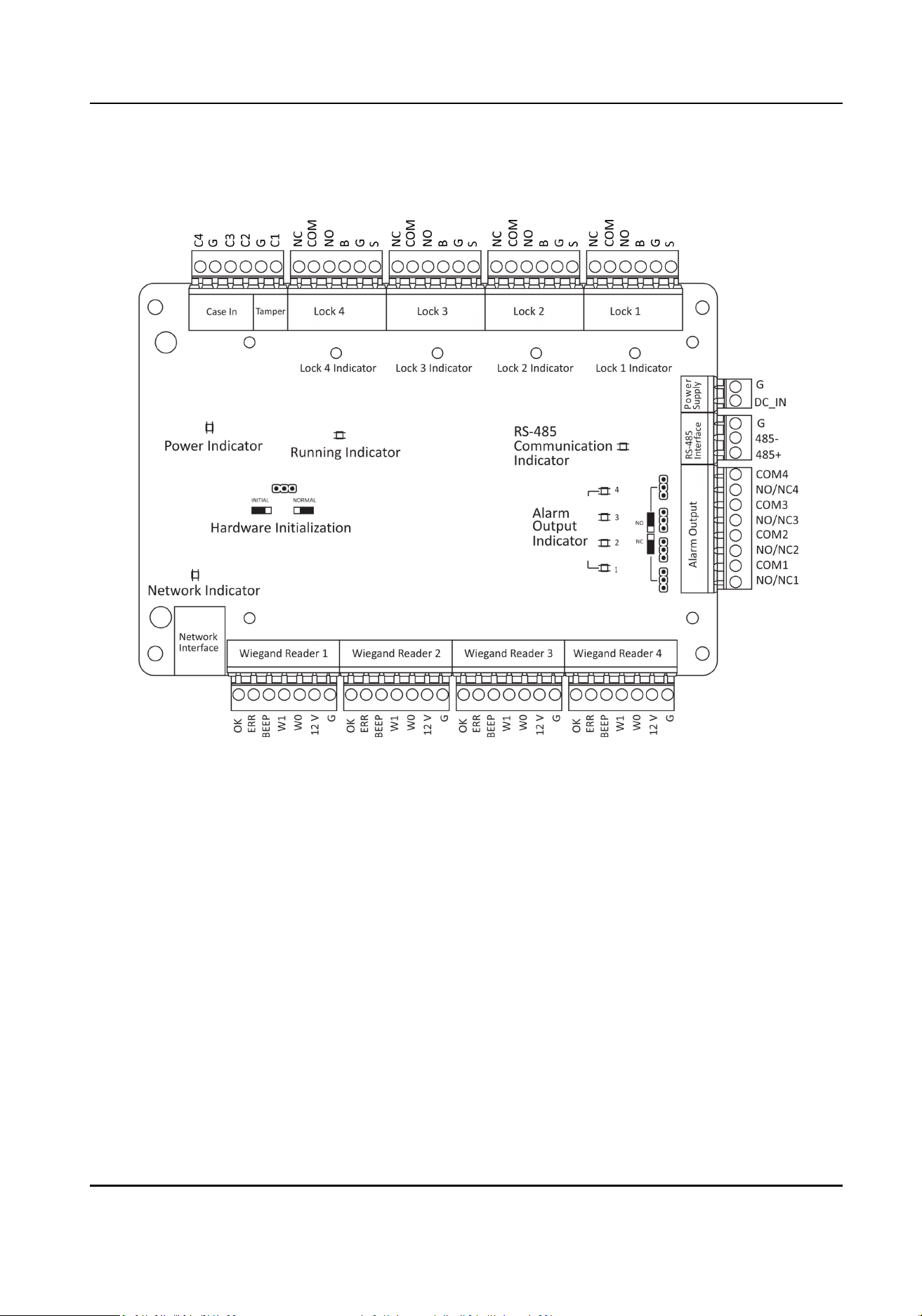
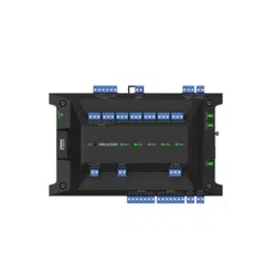
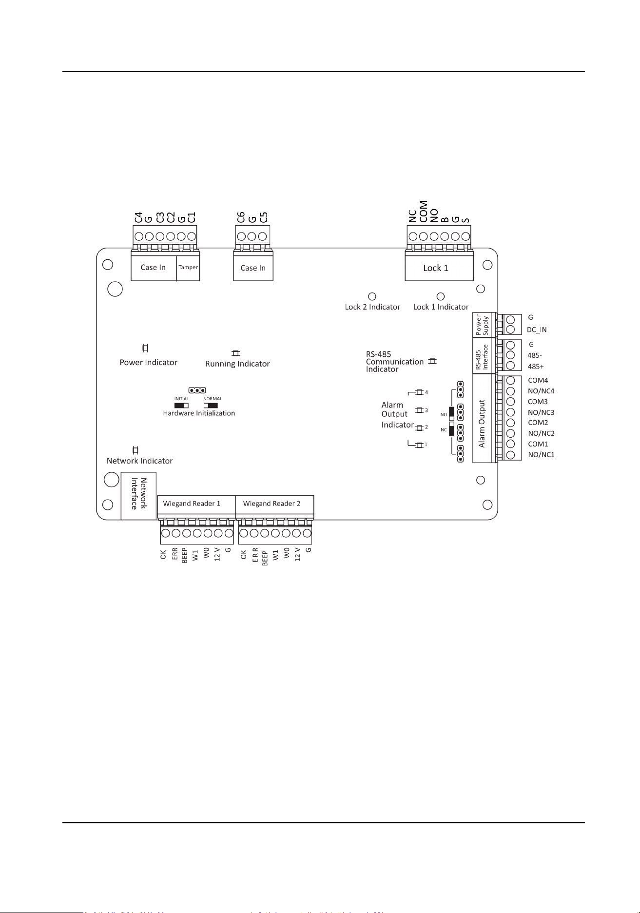
3.2.1 Four-Door Access Controller Main Board Descripon
Figure 3-3 Four-Door Access Controller Main Board
3.3 Component
Descripon
You can view the device's components and their descripons.
Take four-door access controller as an example, the component diagram is shown below.
DS-K281X Series Access Controller User Manual
5
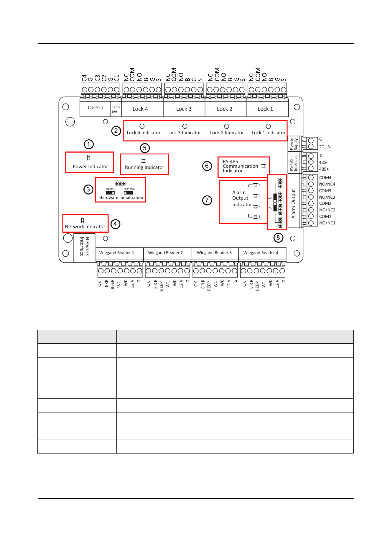
Figure 3-4 Four-Door Access Controller Component Diagram
Table 3-1 Four-Door Access Controller Component
Descripon
No. Component Descripon
1 Power Indicator
2 Lock Indicator
3 Hardware Inializaon and Normal Working Choice
4 Network Indicator
5 Running Indicator
6 RS-485 Communicaon Indicator
7 Alarm Output Indicator
8 Door Relay Output Status (NC/NO) Choice
DS-K281X Series Access Controller User Manual
6
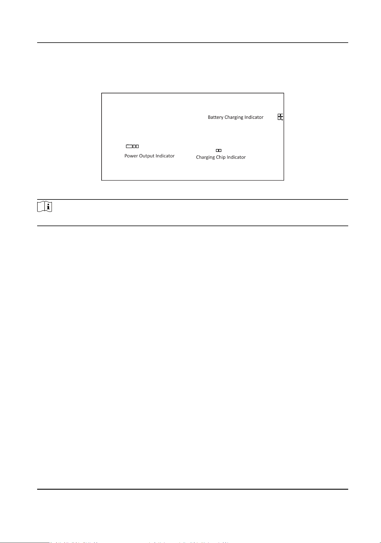
3.4 Baery Charging Board
Figure 3-5 Baery Charging Board
Note
The baery charging boards are only for devices that support baery.
DS-K281X Series Access Controller User Manual
7
Chapter 4 Terminal Descripon
4.1 Single-Door Access Controller Terminal Descripon
You can view the single-door access controller's terminal descripon.
Figure 4-1 Single-Door Access Controller Main Board
DS-K281X Series Access Controller User Manual
8

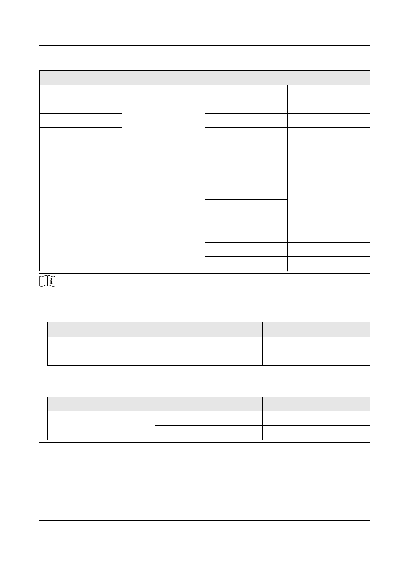
Table 4-1 Single-Door Access Controller Terminal Descripon
No. Four-Door Access Controller
A1~A28 Wiegand Reader 1~4 OK Indicator of Card
Reader Control Output
(Valid Card Output)
ERR Indicator of Card
Reader Control Output
(Invalid Card Output)
BEEP Card Reader Buzzer
Control Output
W1 Wiegand Card Reader
Data Input Data1
W0 Wiegand Card Reader
Data Input Data0
12 V Wiegand Card Reader
Data Input Data0
G Grounding
B1 Power Supply G Grounding
B2 DC_IN Power In
B3 RS-485 Interface G Grounding
B4 485- Card Reader 485-
B5 485+ Card Reader 485+
B6~B13 Alarm Output COM4 Alarm Relay 4Output
(Dry Contact)
NO/NC4
COM3 Alarm Relay 3 Output
(Dry Contact)
NO/NC3
COM2 Alarm Relay 2 Output
(Dry Contact)
NO/NC2
COM1 Alarm Relay 1 Output
(Dry Contact)
NO/NC1
C1 Event In C4 Event In 4
C2 G Grounding
DS-K281X Series Access Controller User Manual
9
No. Four-Door Access Controller
C3 C3 Event In 3
C4 Tamper C2 Reserved
C5 G Grounding
C6 C1 Tamper
C7 Event In C6 Event In 6
C8 G Grounding
C9 C5 Event In 5
C10~C15 Lock 1 NC Lock Relay Output (Dry
Contact)
COM
NO
B Exit Buon In
G Grounding
S Door Contact
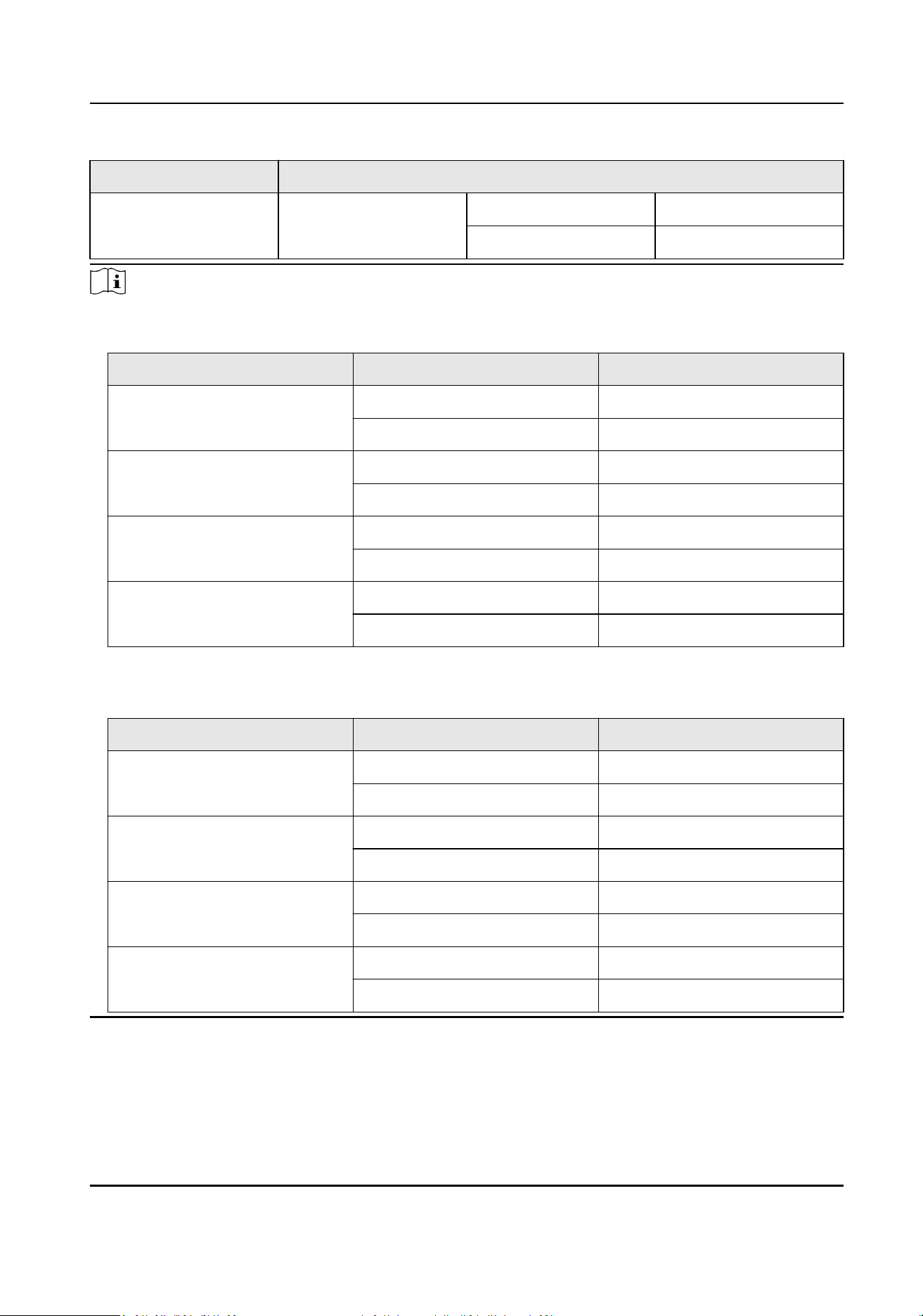
Note
●
RS-485 card reader ID should be set as 1to 2. The table displayed below shows the relaonship
between the door No. and the ID.
Door No. RS-485 Card Reader ID Descripon
Door 1 1 Enter
2 Exit
●
For single-door access controller, the Wiegand card reader and door's relaonship is as follows
by default.
Door No. Wiegand Card Reader Descripon
Door 1 1 Enter
2 Exit
4.2 Two-Door Access Controller Terminal Descripon
You can view the two-door access controller's terminal descripon.
DS-K281X Series Access Controller User Manual
10
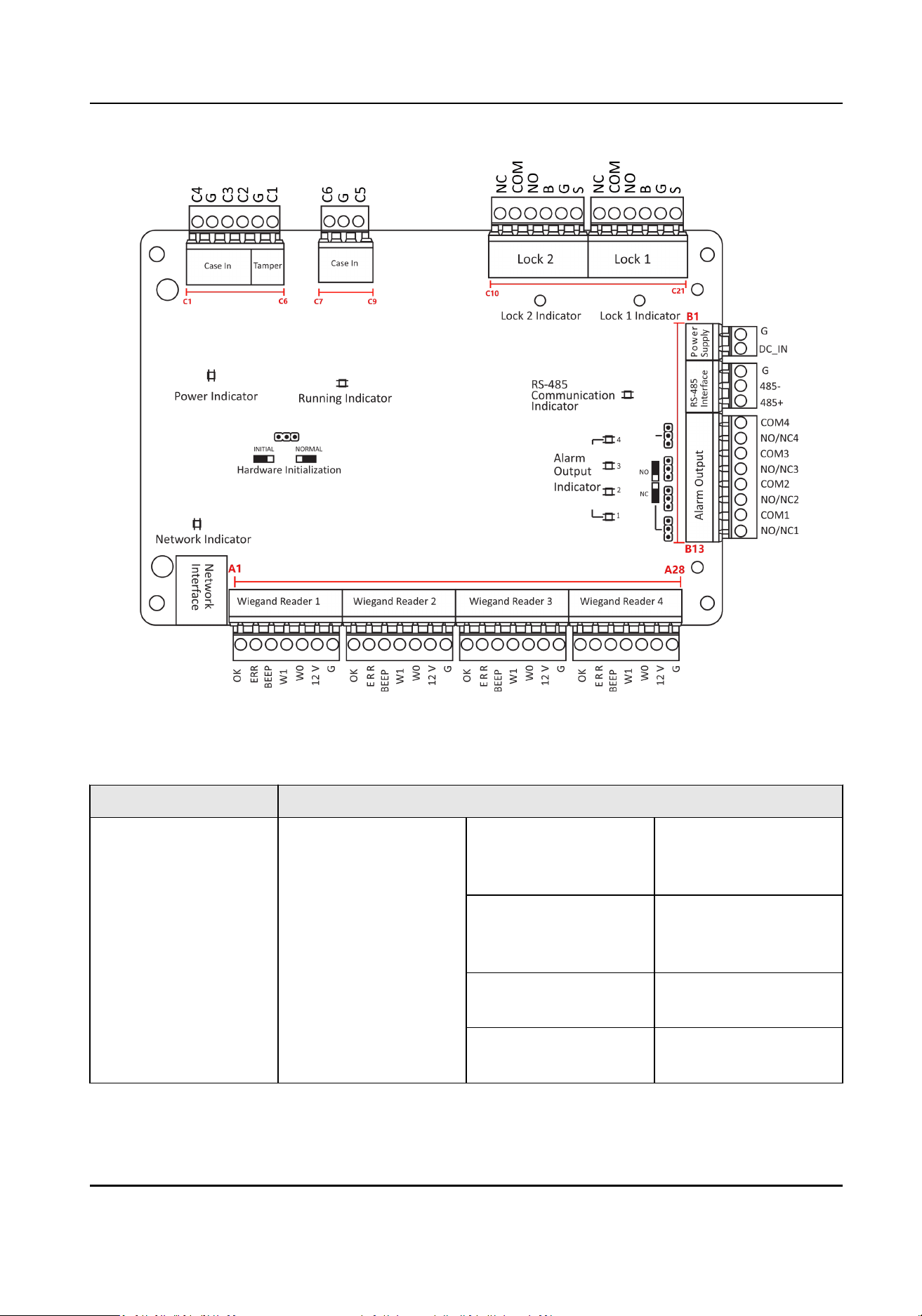
Figure 4-2 Two-Door Access Controller Main Board
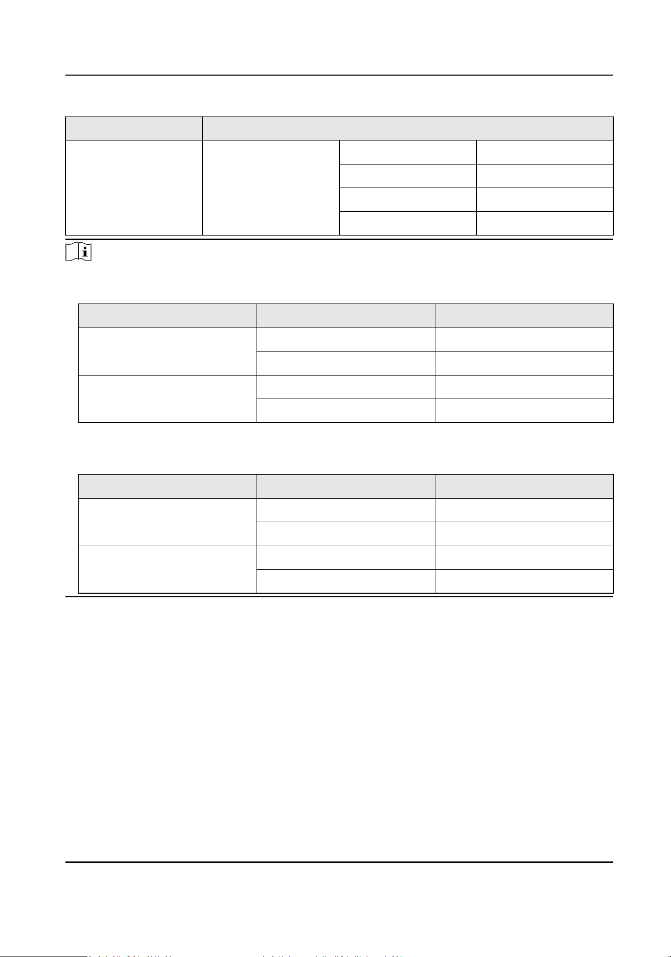
Table 4-2 Two-Door Access Controller Terminal
Descripon
No. Four-Door Access Controller
A1~A28 Wiegand Reader 1~4 OK Indicator of Card
Reader Control Output
(Valid Card Output)
ERR Indicator of Card
Reader Control Output
(Invalid Card Output)
BEEP Card Reader Buzzer
Control Output
W1 Wiegand Card Reader
Data Input Data1
DS-K281X Series Access Controller User Manual
11

No. Four-Door Access Controller
W0 Wiegand Card Reader
Data Input Data0
12 V Wiegand Card Reader
Data Input Data0
G Grounding
B1 Power Supply G Grounding
B2 DC_IN Power In
B3 RS-485 Interface G Grounding
B4 485- Card Reader 485-
B5 485+ Card Reader 485+
B6~B13 Alarm Output COM4 Alarm Relay 4Output
(Dry Contact)
NO/NC4
COM3 Alarm Relay 3 Output
(Dry Contact)
NO/NC3
COM2 Alarm Relay 2 Output
(Dry Contact)
NO/NC2
COM1 Alarm Relay 1 Output
(Dry Contact)
NO/NC1
C1 Event In C4 Event In 4
C2 G Grounding
C3 C3 Event In 3
C4 Tamper C2 Reserved
C5 G Grounding
C6 C1 Tamper
C7 Event In C6 Event In 6
C8 G Grounding
C9 C5 Event In 5
C10~C21 Lock 1~Lock 2 NC Lock Relay Output (Dry
Contact)
COM
DS-K281X Series Access Controller User Manual
12
No. Four-Door Access Controller
NO
B Exit Buon In
G Grounding
S Door Contact
Note
●
RS-485 card reader ID should be set as 1 to 8.
Door No. RS-485 Card Reader ID Descripon
Door 1 1 Enter
2 Exit
Door 2 3 Enter
4 Exit
●
For two-door access controller, the Wiegand card reader and door's relaonship is as follows by
default.
Door No. Wiegand Card Reader Descripon
Door 1 1 Enter
2 Exit
Door 2 3 Enter
4 Exit
4.3 Four-Door Access Controller Terminal Descripon
You can view the four-door access controller's terminal descripon.
DS-K281X Series Access Controller User Manual
13

Figure 4-3 Four-Door Access Controller Main Board
Table 4-3 Four-Door Access Controller Terminal
Descripon
No. Four-Door Access Controller
A1~A28 Wiegand Reader 1~4 OK Indicator of Card
Reader Control Output
(Valid Card Output)
ERR Indicator of Card
Reader Control Output
(Invalid Card Output)
BEEP Card Reader Buzzer
Control Output
W1 Wiegand Card Reader
Data Input Data1
DS-K281X Series Access Controller User Manual
14

No. Four-Door Access Controller
W0 Wiegand Card Reader
Data Input Data0
12 V Wiegand Card Reader
Data Input Data0
G Grounding
B1 Power Supply G Grounding
B2 DC_IN Power In
B3 RS-485 Interface G Grounding
B4 485- Card Reader 485-
B5 485+ Card Reader 485+
B6~B13 Alarm Output COM4 Alarm Relay 4Output
(Dry Contact)
NO/NC4
COM3 Alarm Relay 3 Output
(Dry Contact)
NO/NC3
COM2 Alarm Relay 2 Output
(Dry Contact)
NO/NC2
COM1 Alarm Relay 1 Output
(Dry Contact)
NO/NC1
C1 Event In C4 Event In 4
C2 G Grounding
C3 C3 Event In 3
C4 Tamper C2 Reserved
C5 G Grounding
C6 C1 Tamper
C7~C30 Lock 1~4 NC Lock Relay Output (Dry
Contact)
COM
NO
B Exit Buon In
DS-K281X Series Access Controller User Manual
15
No. Four-Door Access Controller
G Grounding
S Door Contact
Note
●
RS-485 card ID should be set as 1 to 8.
Door No. RS-485 Card Reader ID Descripon
Door 1 1 Enter
2 Exit
Door 2 3 Enter
4 Exit
Door 3 5 Enter
6 Exit
Door4 7 Enter
8 Exit
●
For four-door access controller, the Wiegand card reader and door's relaonship is as follows by
default.
Door No. Wiegand Card Reader Descripon
Door 1 1 Enter
/ Exit
Door 2 2 Enter
/ Exit
Door 3 3 Enter
/ Exit
Door 4 4 Enter
/ Exit
DS-K281X Series Access Controller User Manual
16

Chapter 5 Installaon
5.1 Wall Mounng
The access controller can be installed on the wall.
Steps
1.
Note
In the process of installing, aer roung the cable through the knockout, the knockout should be
sealed with ame-retardant clay or a plug that achieves the rang of V-1.
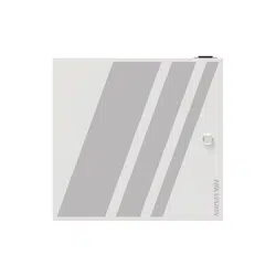
Open and take o the case door.
Figure 5-1 Open the case door
2.
Secure the device on the wall with expansion screws.
DS-K281X Series Access Controller User Manual
17
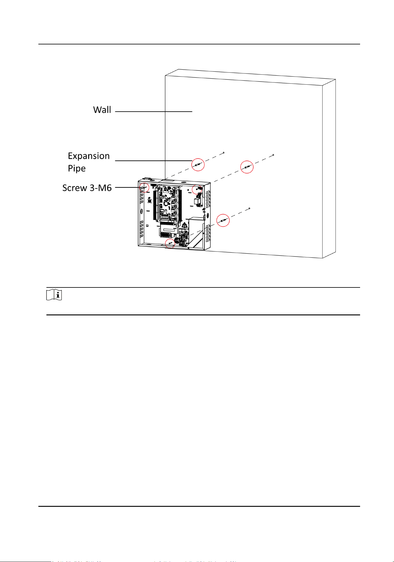
Figure 5-2 Secure the device
3.
Aer wiring, recover the case door and boom.
Note
When wiring, you can open knockouts to your actual needs.
DS-K281X Series Access Controller User Manual
18
Chapter 6 Terminal Wiring
Terminal Wiring Descripon of the Access Controller.
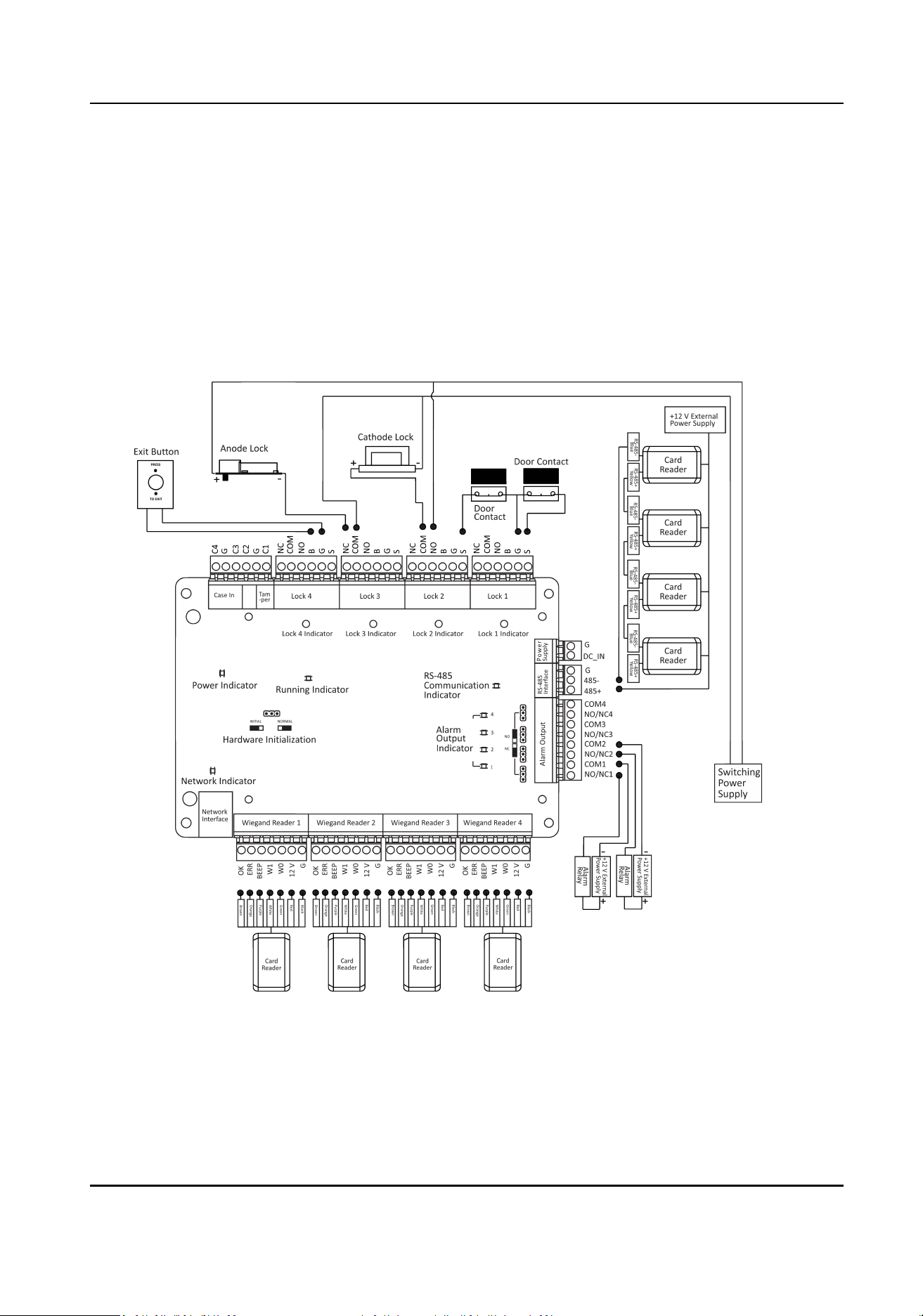
6.1 Main Board Wiring
You can view the main board wiring diagram.
Figure 6-1 Access Controller Main Board Wiring
DS-K281X Series Access Controller User Manual
19
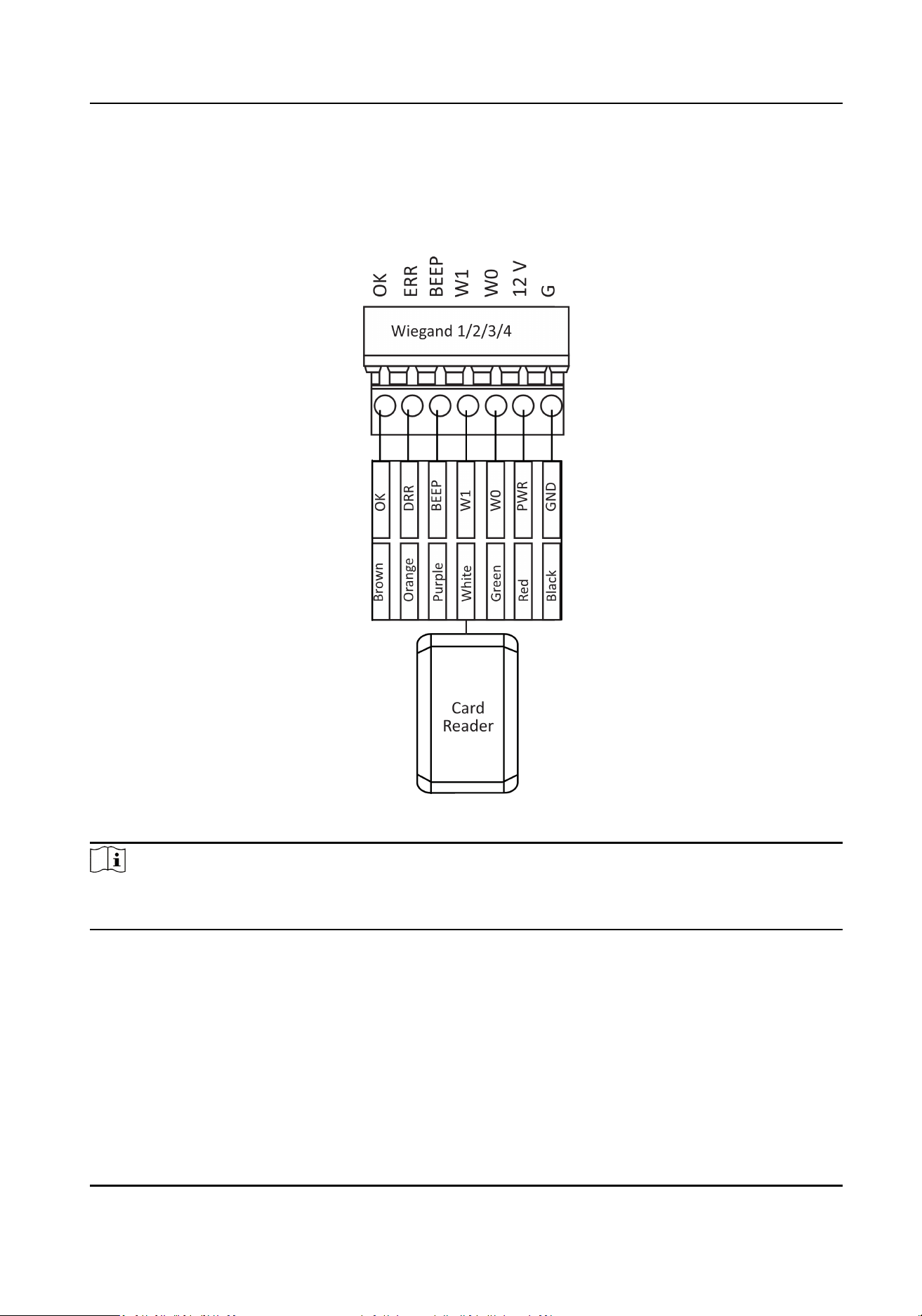
6.2 Wiegand Card Reader Wiring
You can view the Wiegand card reader wiring diagram.
Figure 6-2 Wiegand Card Reader Wiring Diagram
Note
You must connect the OK/ERR/BZ, if using access controller to control the LED and buzzer of the
Wiegand card reader.
6.3 RS-485 Card Reader Wiring
You can view the RS-485 card reader wiring diagram.
DS-K281X Series Access Controller User Manual
20
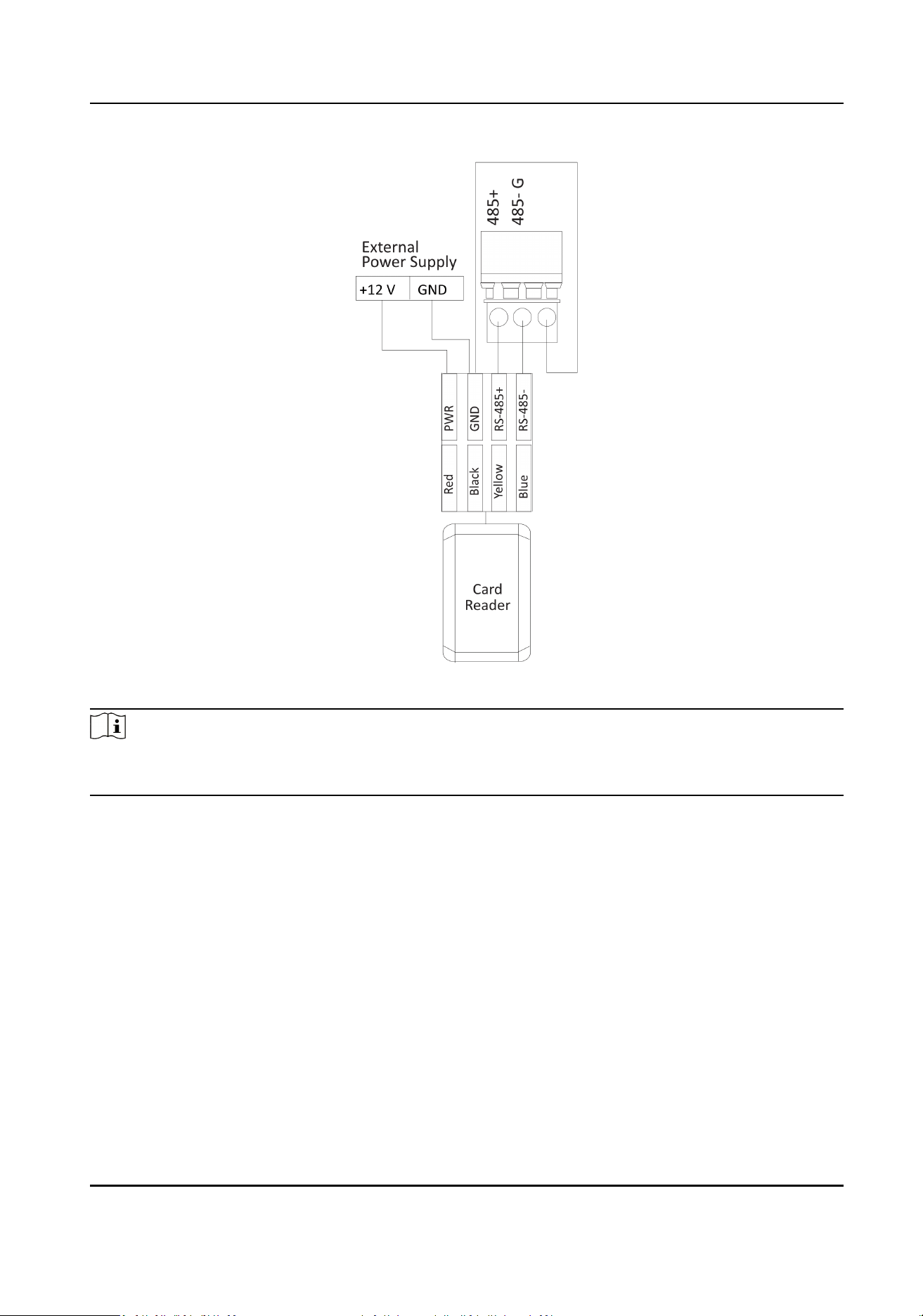
Figure 6-3 RS-485 Card Reader Wiring Diagram
Note
If the card reader is installed too far away from the access controller, you can use an external
power supply.
6.4 Cathode Lock Wiring
You can view the cathode lock wiring diagram.
DS-K281X Series Access Controller User Manual
21
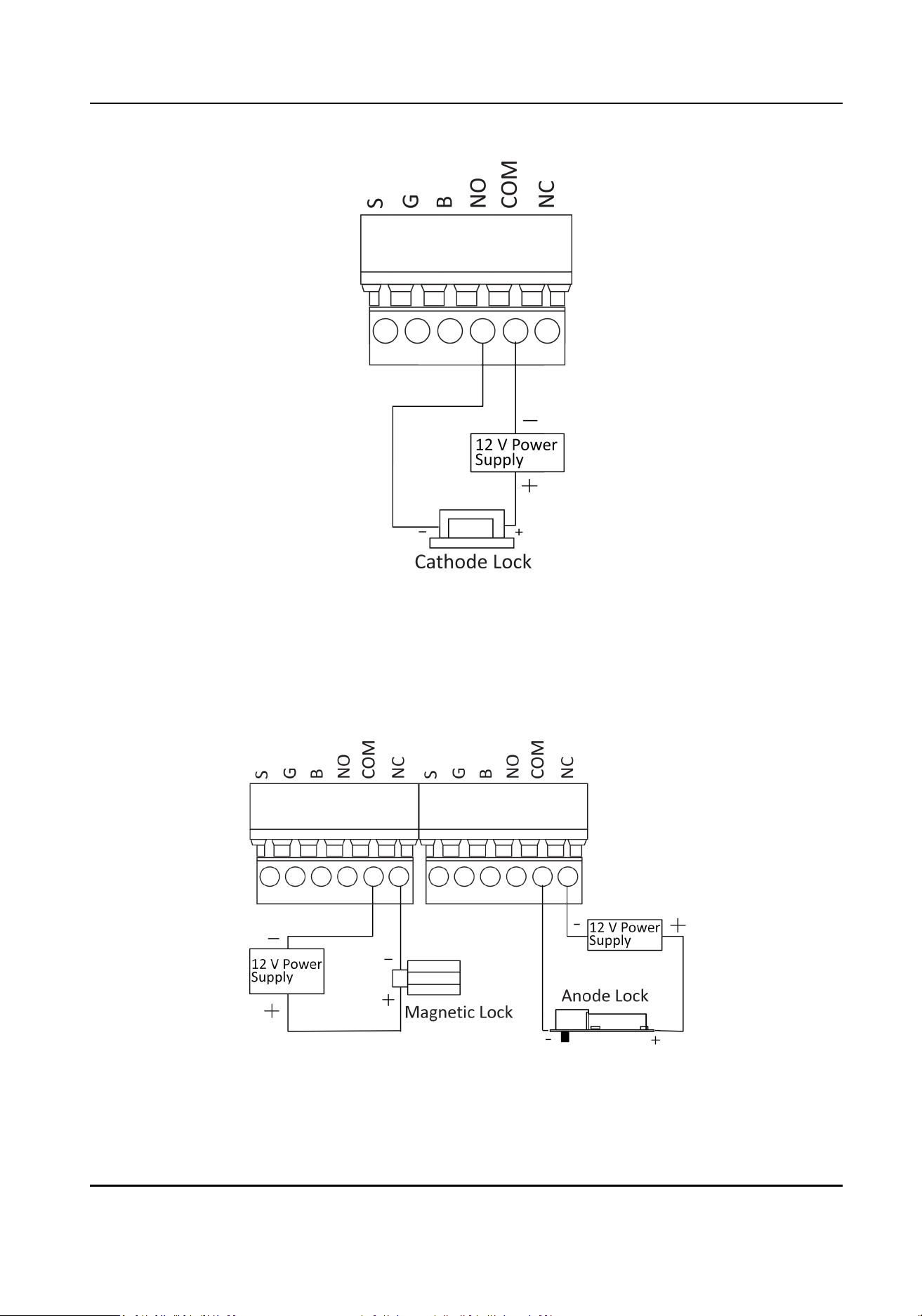
Figure 6-4 Wiring Diagram of Cathode Lock
6.5 Anode Lock Wiring
You can view the anode lock wiring diagram.
Figure 6-5 Wiring Diagram of Anode Lock
DS-K281X Series Access Controller User Manual
22
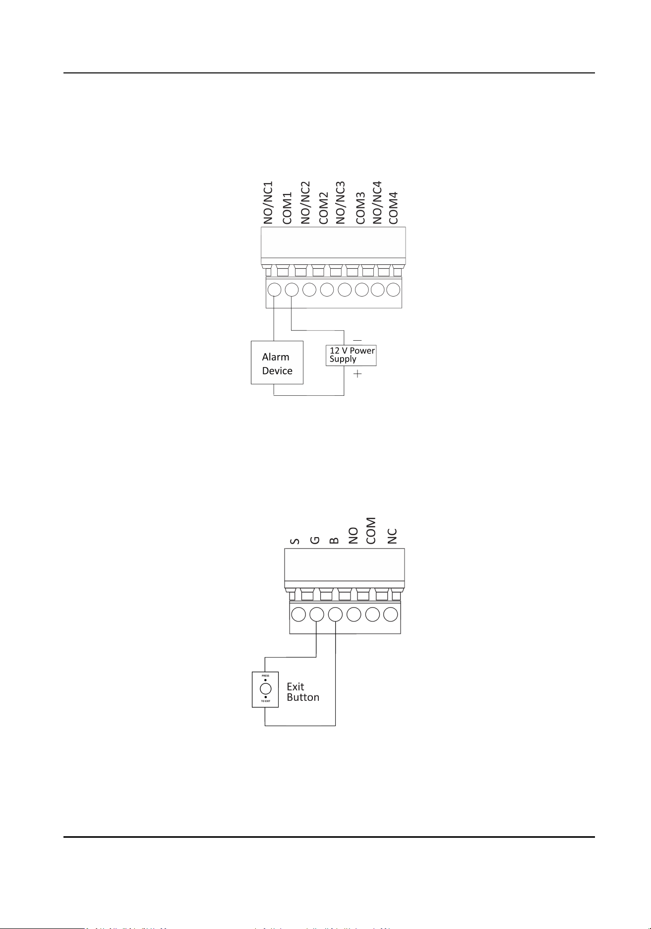
6.6 Alarm Output Wiring
You can view the Alarm Output Wiring diagram.
Figure 6-6 Alarm Output Wiring
6.7 Exit
Buon Wiring
You can view the exit buon wiring diagram
Figure 6-7 Exit Buon Wiring
DS-K281X Series Access Controller User Manual
23
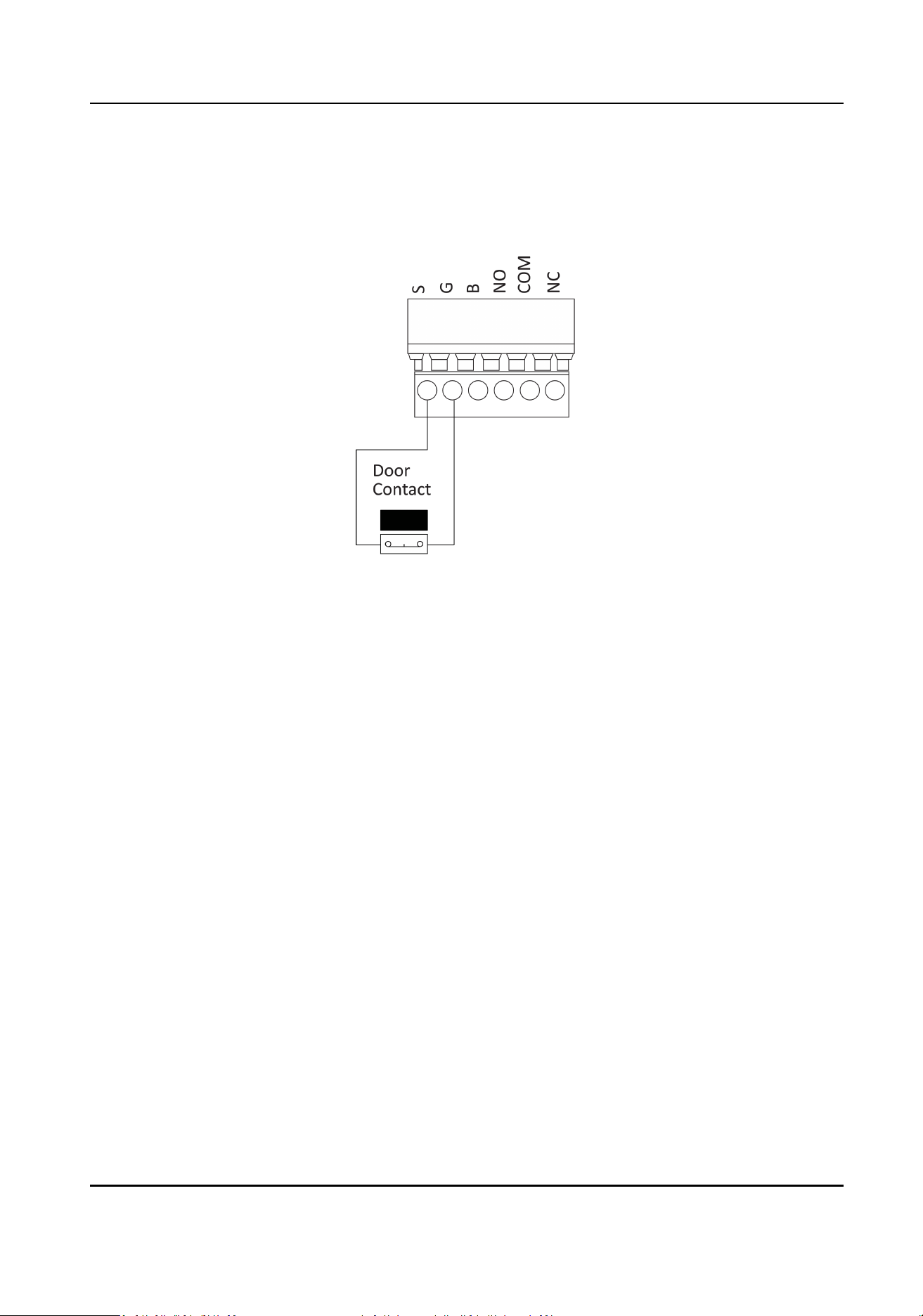
6.8 Door Contact Wiring
You can view the door contact wiring diagram.
Figure 6-8 Door Contact Wiring
6.9 Power Supply Wiring
You can view the power supply wiring diagram.
DS-K281X Series Access Controller User Manual
24
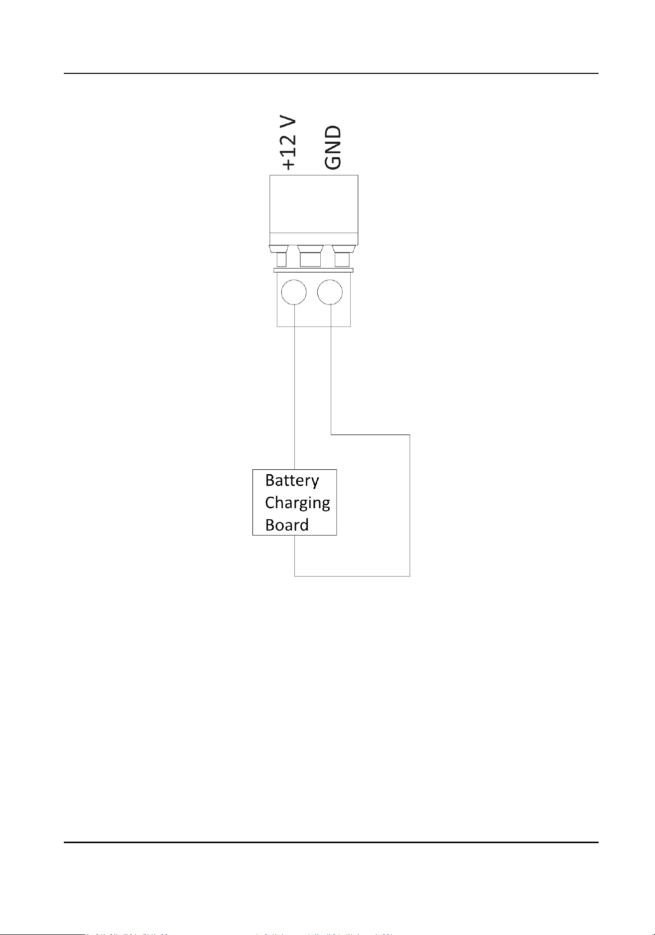
Figure 6-9 Power Supply Wiring
DS-K281X Series Access Controller User Manual
25
Chapter 7 Sengs
7.1 Inializaon (Opon 1)
You can inialize the device with the jumper cap.
Steps
1.
Remove the jumper cap from the Normal terminal.
2.
Cut o the power and restart the access controller.
The controller buzzer buzzes a long beep.
3.
When the beep stopped, plug the jumper cap back to Normal.
4.
Cut
o the power and restart the access controller.
Figure 7-1 Inializaon Jumper
Note
The device inializaon will restore all the parameters to the default sengs and all the device
event logs will be deleted.
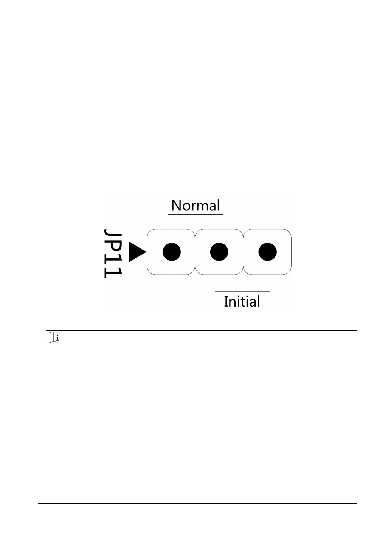
7.2 Inializaon (Opon 2)
You can inialize the device with the jumper cap.
Steps
1.
Move the jumper cap from Normal to Inial.
2.
Cut o the power and restart the access controller.
The controller buzzer buzzes a long beep.
3.
When the beep stopped, move the jumper cap back to Normal.
4.
Cut
o the power and restart the access controller.
DS-K281X Series Access Controller User Manual
26
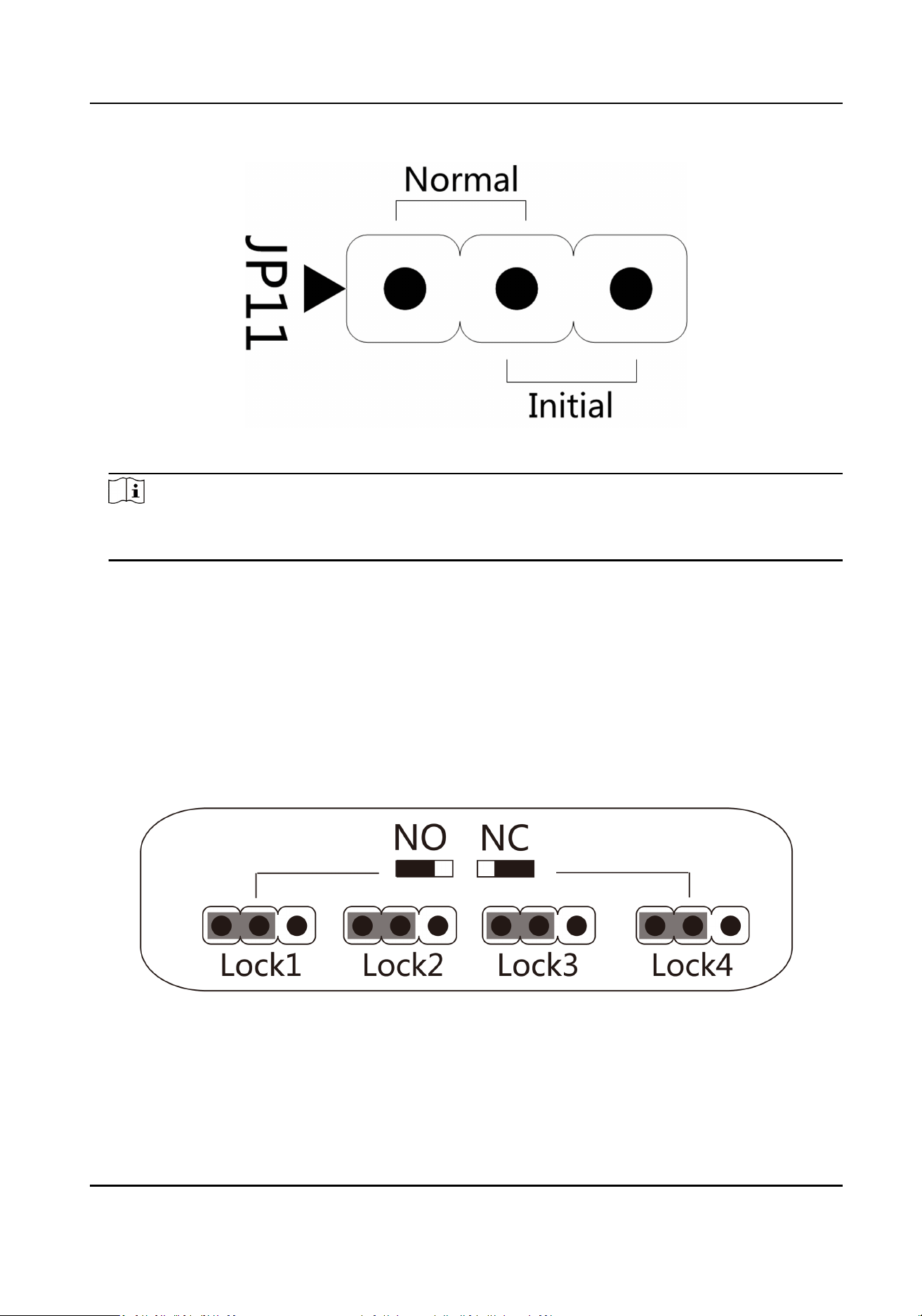
Figure 7-2 Inializaon Jumper
Note
The device inializaon will restore all the parameters to the default sengs and all the device
event logs will be deleted.
7.3 Relay Output NO/NC Sengs
7.3.1 Lock Relay Output Sengs
You can view the NO/NC status of the lock relay.
Lock Relay NO Status
Figure 7-3 NO Status
DS-K281X Series Access Controller User Manual
27
Lock Relay NC Status
Figure 7-4 NC Status
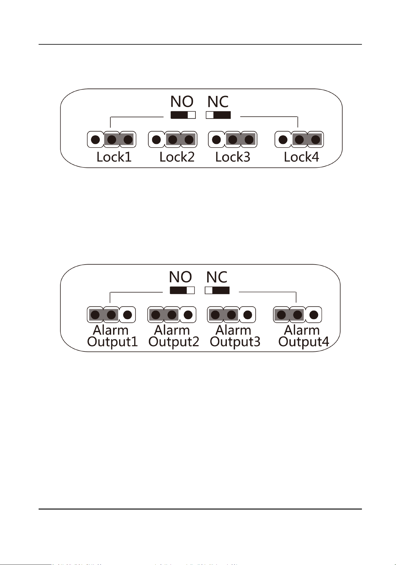
7.3.2 Alarm Relay Output
Sengs
You can view the NO/NC status of the alarm relay.
Alarm Relay Output NO Status
Figure 7-5 NO Status
DS-K281X Series Access Controller User Manual
28
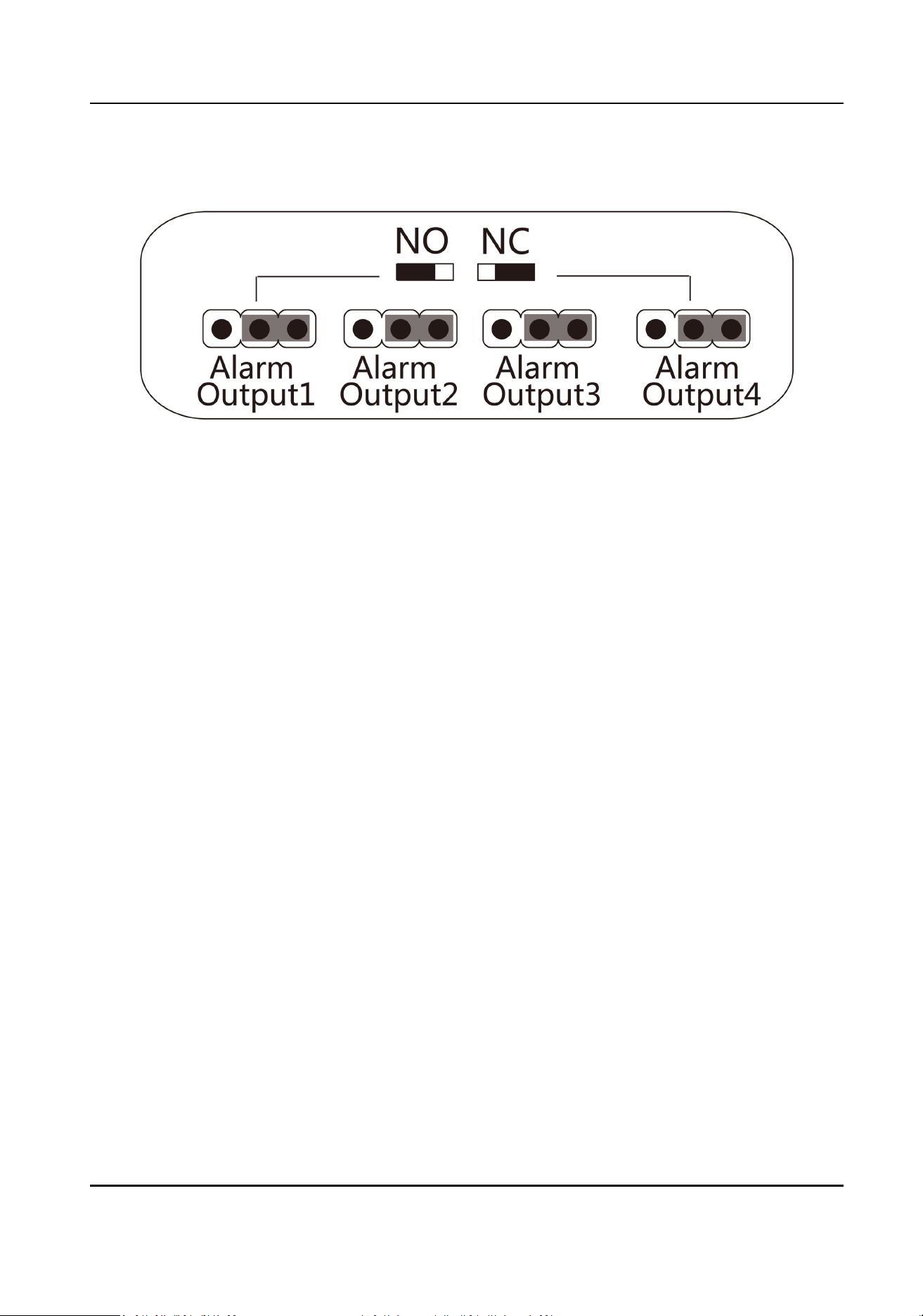
Alarm Relay Output NC Status
Figure 7-6 NC Status
DS-K281X Series Access Controller User Manual
29

Chapter 8 Acvaon
You should acvate the device before the rst login. Aer powering on the device, the system will
switch to Device
Acvaon page.
Acvaon via the device, SADP tool and the client soware are supported.
The default values of the device are as follows:
●
The default IP address: 192.0.0.64
●
The default port No.: 8000
●
The default user name: admin
8.1
Acvate via SADP
SADP is a tool to detect, acvate and modify the IP address of the device over the LAN.
Before You Start
●
Get the SADP soware from the supplied disk or the ocial website hp://
www.hikvision.com/en/ , and install the SADP according to the prompts.
●
The device and the PC that runs the SADP tool should be within the same subnet.
The following steps show how to acvate a device and modify its IP address. For batch acvaon
and IP addresses modicaon, refer to User Manual of SADP for details.
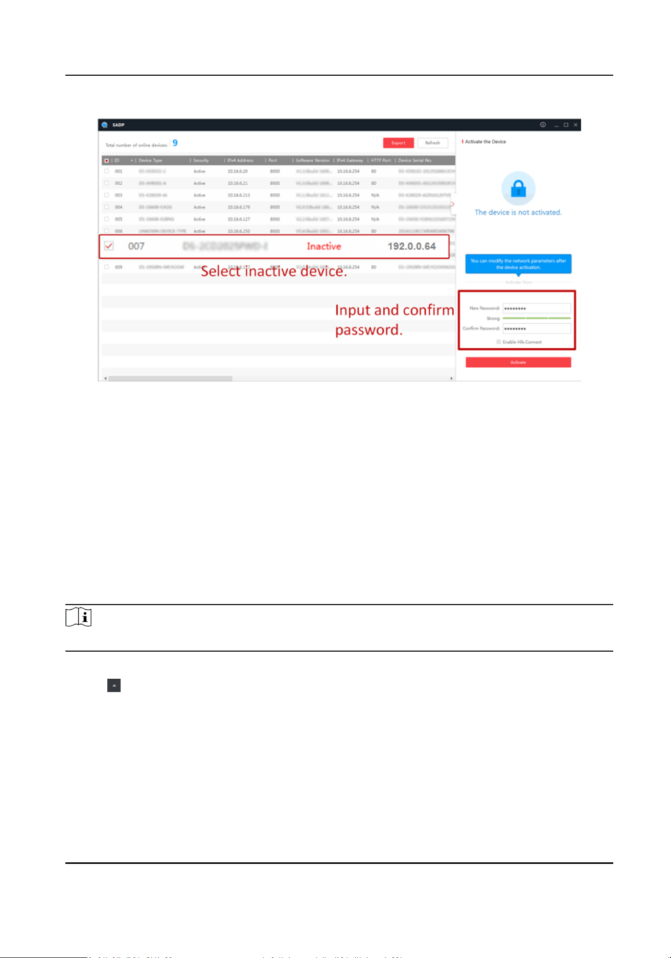
Steps
1.
Run the SADP soware and search the online devices.
2.
Find and select your device in online device list.
3.
Input new password (admin password) and
conrm the password.
Cauon
STRONG PASSWORD RECOMMENDED-We highly recommend you create a strong password of
your own choosing (using a minimum of 8 characters, including upper case leers, lower case
leers, numbers, and special characters) in order to increase the security of your product. And
we recommend you reset your password regularly, especially in the high security system,
reseng the password monthly or weekly can beer protect your product.
Note
Characters containing admin and nimda are not supported to be set as acvaon password.
4.
Click Acvate to start acvaon.
DS-K281X Series Access Controller User Manual
30
Status of the device becomes Acve aer successful acvaon.
5.
Modify IP address of the device.
1) Select the device.
2) Change the device IP address to the same subnet as your computer by either modifying the IP
address manually or checking Enable DHCP.
3) Input the admin password and click Modify to
acvate your IP address modicaon.
8.2
Acvate Device via Client Soware
For some devices, you are required to create the password to acvate them before they can be
added to the
soware and work properly.
Steps
Note
This funcon should be supported by the device.
1.
Enter the Device Management page.
2.
Click on the right of Device Management and select Device.
3.
Click Online Device to show the online device area.
The searched online devices are displayed in the list.
4.
Check the device status (shown on Security Level column) and select an
inacve device.
5.
Click
Acvate to open the Acvaon dialog.
6.
Create a password in the password eld, and conrm the password.
DS-K281X Series Access Controller User Manual
31
Cauon
The password strength of the device can be automacally checked. We highly recommend you
change the password of your own choosing (using a minimum of 8 characters, including at least
three kinds of following categories: upper case leers, lower case leers, numbers, and special
characters) in order to increase the security of your product. And we recommend you reset your
password regularly, especially in the high security system, reseng the password monthly or
weekly can
beer protect your product.
Proper conguraon of all passwords and other security sengs is the responsibility of the
installer and/or end-user.
Note
Characters containing admin and nimda are not supported to be set as acvaon password.
7.
Click OK to acvate the device.
DS-K281X Series Access Controller User Manual
32
Chapter 9 Client Soware Conguraon
You can call the hotline to get the iVMS-4200 client soware installaon package.
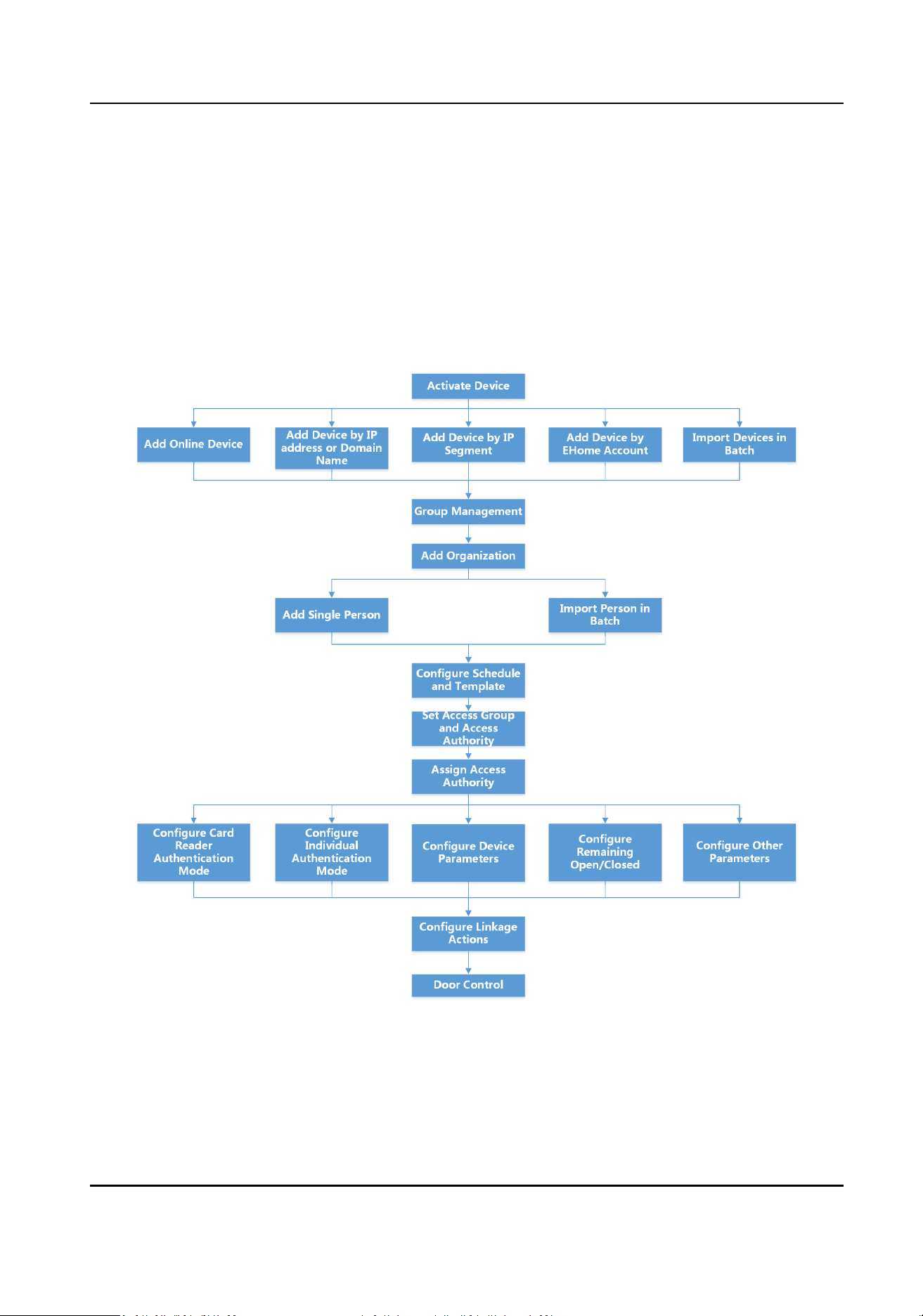
9.1 Conguraon Flow of Client Soware
Follow the ow diagram below to congure on the client soware.
Figure 9-1 Flow Diagram of Conguraon on Client Soware
DS-K281X Series Access Controller User Manual
33

9.2 Device Management
The client supports managing access control devices and video intercom devices.
Example
You can control entrance & exit and manage aendance aer adding access control devices to the
client; you can perform video intercom with the indoor staons and door staons.
9.2.1 Add Device
Aer
running the client, devices should be added to the client for the remote conguraon and
management.
Aer adding device(s), you can select a device and click Remote Conguraon to congure further
parameters of the selected device if needed. You can also
Note
For some models of devices, you can open its general or advanced parameters conguraon
window. To open the original remote conguraon window, press CTRL and click Remote
Conguraon.
Aer adding access control devices, you can select access control device from the list and click
Device Status to view the device status.
Add Device by IP Address or Domain Name
You can add device by IP address or domain name.
Perform this task if you need to add device by IP address or domain name.
Steps
1.
Open the Device Management module.
2.
Click Device tab and select Hikvision Device as the device type.
3.
Click Add to open the Add window.
4.
Select IP/Domain as the adding mode.
5.
Input the required
informaon, including nickname, IP address, port number, user name, and
password.
Address
Input the device IP addresss or domain name.
Port
Input the device port No. The default value is 8000.
User Name
DS-K281X Series Access Controller User Manual
34
Input the device user name. By default, the user name is admin.
Password
Input the device password.
Cauon
The password strength of the device can be automacally checked. We highly recommend you
change the password of your own choosing (using a minimum of 8 characters, including at
least three kinds of following categories: upper case leers, lower case leers, numbers, and
special characters) in order to increase the security of your product. And we recommend you
reset your password regularly, especially in the high security system, reseng the password
monthly or weekly can
beer protect your product.
Proper conguraon of all passwords and other security sengs is the responsibility of the
installer and/or end-user.
6.
Oponal: Check Synchronize Device Time to synchronize the device me with the PC running
the client
aer adding the device to the client.
7.
Oponal: Check Export to Group to create a group by the device name.
Note
You can import all the channels of the device to the corresponding group by default.
8.
Oponal: Add the oine devices.
1) Check Add Oine Device.
2) Input the required
informaon, including the device channel number and alarm input
number.
3) Click Add.
When the
oine device comes online, the soware will connect it automacally.
9.
Click Add to add the device.
Import Devices in a Batch
The devices can be added to the soware in batch by inpung the device informaon in the pre-
dened
CSV le.
Perform this task to import devices in a batch.
Steps
1.
Enter the Device Management page
2.
Click Device → Hikvision Device → Add to open the adding device window.
3.
Select Batch Import as the adding mode.
4.
Click Export Template and then save the
pre-dened template (CSV le) on your PC.
5.
Open the exported template
le and input the required informaon of the devices to be added
on the corresponding column.
Adding Mode
DS-K281X Series Access Controller User Manual
35

You can input 0, 2, 3, 4, 5, or 6 which indicated dierent adding modes. 0 indicates that the
device is added by IP address or domain name; 2 indicates that the device is added via IP
server; 3 indicates that the device is added via HiDDNS; 4 indicates that the device is added via
EHome protocol; 5 indicates that the device is added by serial port; 6 indicates that the device
is added via Hik-Connect.
Address
Edit the address of the device. If you set 0 as the adding mode, you should input the IP address
or domain name of the device; if you set 2 as the adding mode, you should input the IP
address of the PC that installs the IP Server; if you set 3 as the adding mode, you should input
www.hik-online.com.
Port
Input the device port No. The default value is 8000.
Device
Informaon
If you set 0 as the adding mode, this eld is not required; if you set 2 as the adding mode, input
the device ID registered on the IP Server; if you set 3 as the adding mode, input the device
domain name registered on HiDDNS server; if you set 4 as the adding mode, input the EHome
account; if you set 6 as the adding mode, input the device serial No.
User Name
Input the device user name. By default, the user name is admin.
Password
Input the device password.
Cauon
The password strength of the device can be automacally checked. We highly recommend you
change the password of your own choosing (using a minimum of 8 characters, including at
least three kinds of following categories: upper case leers, lower case leers, numbers, and
special characters) in order to increase the security of your product. And we recommend you
reset your password regularly, especially in the high security system, reseng the password
monthly or weekly can
beer protect your product.
Proper conguraon of all passwords and other security sengs is the responsibility of the
installer and/or end-user.
Add Oine Device
You can input 1 to enable adding the
oine device, and then the soware will automacally
connect it when the oine device comes online. 0 indicates disabling this funcon.
Export to Group
You can input 1 to create a group by the device name (nickname). All the channels of the
device will be imported to the corresponding group by default. 0 indicates disabling this
funcon.
DS-K281X Series Access Controller User Manual
36

Channel Number
If you set 1 for Add Oine Device, input the channel number of the device. If you set 0 for Add
Oine Device, this eld is not required.
Alarm Input Number
If you set 1 for Add
Oine Device, input the alarm input number of the device. If you set 0 for
Add Oine Device, this eld is not required.
Serial Port No.
If you set 5 as the adding mode, input the serial port No. for the access control device.
Baud Rate
If you set 5 as the adding mode, input the baud rate of the access control device.
DIP
If you set 5 as the adding mode, input the DIP address of the access control device.
Hik-Connect Account
If you set 6 as the adding mode, input the Hik-Connect account.
Hik-Connect Password
If you set 6 as the adding mode, input the Hik-Connect account password.
6.
Click
and select the template le.
7.
Click Add to import the devices.
9.2.2 Reset Device Password
If you forgot the password of the detected online devices, you can reset the device password via
the client.
Steps
1.
Enter Device Management page.
2.
Click Online Device to show the online device area.
All the online devices sharing the same subnet will be displayed in the list.
3.
Select the device from the list and click
on the Operaon column.
4.
Reset the device password.
-
Click Generate to pop up the QR Code window and click Download to save the QR code to
your PC. You can also take a photo of the QR code to save it to your phone. Send the picture
to our technical support.
Note
For the following operaons for reseng the password, contact our technical support.
DS-K281X Series Access Controller User Manual
37

Cauon
The password strength of the device can be automacally checked. We highly recommend you
change the password of your own choosing (using a minimum of 8 characters, including at least
three kinds of following categories: upper case leers, lower case leers, numbers, and special
characters) in order to increase the security of your product. And we recommend you reset your
password regularly, especially in the high security system, reseng the password monthly or
weekly can
beer protect your product.
Proper conguraon of all passwords and other security sengs is the responsibility of the
installer and/or end-user.
9.2.3 Manage Added Devices
Aer adding devices to device list, you can manage the added devices including eding device
parameters, remote conguraon, viewing device status, etc.
Table 9-1 Manage Added Devices
Edit Device Click to edit device informaon including device name, address, user
name, password, etc.
Delete Device Check one or more devices, and click Delete to delete the selected
devices.
Remote Conguraon On the device list page, click in the Operaon column to perform
remote conguraon for a device. The is in the rightmost column of
the Device page. For details, refer to the user manual of device.
View Device Status Click to view device status, including door No., door status, etc.
Note
For dierent devices, you will view dierent informaon about device
status.
View Online User Click to view the details of online user who access the device,
including user name, user type, IP address and login me.
Refresh Device
Informaon
Click to refresh and get the latest device informaon.
Upgrade Device View device status in the Firmware Upgrade column, check one or more
upgradable devices, and click Upgrade Device Firmware to upgrade the
selected devices. For details, refer to .
DS-K281X Series Access Controller User Manual
38
Get Events from Device Check one device, and click Get Events from Device to synchronize
events. For details, refer to .
Export Device Click Export Device, set the saving path and select device type to export
the device details (such as device type, IP address, and port No.) to your
local PC.
Note
The super user can enable Password Protecon and enter the
password, then the exported le of device informaon will be
encrypted.
9.3 Group Management
The client provides groups to manage the added resources in dierent groups. You can group the
resources into dierent groups according to the resources' locaons.
Example
For example, on the 1st oor, there mounted 16 doors, 64 alarm inputs, and 16 alarm outputs. You
can organize these resources into one group (named 1st Floor) for convenient management. You
can control door status, and do some other
operaons of the devices aer managing the resources
by groups.
9.3.1 Add Group
You can add group to organize the added device for convenient management.
Steps
1.
Enter the Device Management module.
2.
Click Device Management → Group to enter the group management page.
3.
Create a group.
-
Click Add Group and enter a group name as you want.
-
Click Create Group by Device Name and select an added device to create a new group by the
name of the selected device.
Note
The resources (such as alarm inputs/outputs, access points, etc.) of this device will be
imported to the group by default.
DS-K281X Series Access Controller User Manual
39
9.3.2 Import Resources to Group
You can import the device resources (such as alarm inputs/outputs, access points, etc.) to the
added group in a batch.
Before You Start
Add a group for managing devices. Refer to
Add Group .
Steps
1.
Enter the Device Management module.
2.
Click Device Management → Group to enter the group management page.
3.
Select a group from the group list and select the resource type as Access Point, Alarm Input,
Alarm Output, etc.
4.
Click Import.
5.
Select the thumbnails/names of the resources in the thumbnail/list view.
Note
You can click or to switch the resource display mode to thumbnail view or to list view.
6.
Click Import to import the selected resources to the group.
9.4 Person Management
You can add person informaon to the system for further operaons such as access control, video
intercom, me and aendance, etc. You can manage the added persons such as issuing cards to
them in a batch,
imporng and exporng person informaon in a batch, etc.
9.4.1 Add
Organizaon
You can add an organizaon and import person informaon to the organizaon for eecve
management of the persons. You can also add a surbodinate organizaon for the added one.
Steps
1.
Enter Person module.
2.
Select a parent organizaon in the le column and click Add in the upper-le corner to add an
organizaon.
3.
Create a name for the added organizaon.
Note
Up to 10 levels of organizaons can be added.
4.
Oponal: Perform the following operaon(s).
Edit
Organizaon Hover the mouse on an added organizaon and click to edit its name.
DS-K281X Series Access Controller User Manual
40
Delete
Organizaon
Hover the mouse on an added organizaon and click to delete it.
Note
●
The lower-level organizaons will be deleted as well if you delete an
organizaon.
●
Make sure there is no person added under the organizaon, or the
organizaon cannot be deleted.
Show Persons in
Sub Organizaon
Check Show Persons in Sub Organizaon and select an organizaon to
show persons in its sub organizaons.
9.4.2 Import and Export Person Idenfy Informaon
You can import the informaon of mulple persons to the client soware in a batch. Meanwhile,
you can also export the person informaon and save them in your PC.
Import Person
Informaon
You can import the informaon of mulple persons (including identy informaon, ngerprint
data, and ngerprint linked card number) to the client soware in a batch by imporng an Excel
le from the local PC.
Perform this task when you need to import the person informaon to the client in a batch.
Steps
1.
Enter Access Control → Person and Card .
2.
Click Import Persons and select Person
Informaon as the content to import.
3.
In the pop-up window, click Download Template for Imporng Person to download the
template
rst.
4.
Input the person informaon in the downloaded template.
f1 to f10
The person's
ngerprint data.
f1card to f10card
The ngerprint's linked card number. If it links to no card, leave it empty.
Note
If the person has mulple cards, separate the card No. with semicolon.
5.
Enter Access Control → Person and Card , click Import Person and select the Excel le with
person informaon.
6.
Click OK to start imporng.
DS-K281X Series Access Controller User Manual
41

Note
If the person No. already exists in the client soware's database, it will replace the person
informaon automacally aer imporng.
Import Person Pictures
Aer imporng face pictures for the added persons to the client, the persons in the pictures can be
idened by an added face recognion terminal. You can either import person pictures one by
one, or import
mulple pictures at a me according to your need.
Before You Start
Be sure to have imported person informaon to the client beforehand.
Steps
1.
Enter the Person module.
2.
Select an added
organizaon in the list, or click Add in the upper-le corner to add an
organizaon and then select it.
3.
Click Import to open the Import panel and check Face.
4.
Oponal: Enable Verify by Device to check whether face recognion device managed in the
client can recognize the face in the photo.
5.
Click
to select a face picture le.
Note
●
The (folder of) face pictures should be in ZIP format.
●
Each picture le should be in JPG format and should be no larger than 200 KB.
●
Each picture le should be named as "Person ID_Name". The Person ID should be the same
with that of the imported person
informaon.
6.
Click Import to start imporng.
The imporng progress and result will be displayed.
Export Person
Informaon
You can export the added persons' informaon to the local PC in an Excel le.
Perform this task when you need to export the added person informaon in a batch.
Steps
1.
Enter Access Control → Person and Card module.
2.
Click Export Person and select Person
Informaon as the content to export.
3.
Select the path for saving the exported Excel le.
4.
Select the items of person informaon to export.
5.
Click OK to start
exporng.
DS-K281X Series Access Controller User Manual
42
f1 to f10
The person's ngerprint data.
f1card to f10card
The ngerprint's linked card number. If it links to no card, leave it empty.
Export Person Pictures
You can export face picture le of the added persons and save in your PC.
Before You Start
●
Make sure you have added persons and their face pictures to an
organizaon.
●
Make sure you have enabled the Export Person Informaon funcon to display the Export
buon. See for details.
Steps
1.
Enter the Person module.
2.
Oponal: Select an organizaon in the list.
Note
All persons' face pictures will be exported if you do not select any organizaon.
3.
Click Export on the top menu bar.
4.
Enter the super user name and password for vericaon.
The Export panel is displayed.
5.
Check Face as the content to export.
6.
Click Export and set an
encrypon key to encrypt the exported le.
Note
●
The exported le is in ZIP format.
●
The exported face picture is named as "Person ID_Name_0" ("0" is for a full-frontal face).
9.4.3 Get Person Informaon from Access Control Device
If the access control device has been congured with person informaon (including person details,
ngerprint, and issued card informaon), you can get the person informaon from the added
device and import them to the client for further operaons.
DS-K281X Series Access Controller User Manual
43

Steps
Note
●
If the person name stored in the device is empty, the person name will be lled with the issued
card No. aer imporng to the client.
●
If the card number or person ID (employee ID) stored on the device already exists in the client
database, the person with this card number or person ID will not be imported to the client.
1.
Enter Person module.
2.
Select an
organizaon to import the persons.
3.
Click Get from Device.
4.
Select an added access control device or the enrollment staon from the drop-down list.
Note
If you select the enrollment staon, you should click Login, and enter IP address, port No., user
name and password of the device.
5.
Select the Geng Mode.
Note
The geng mode varies according to dierent devices. The access control device supports
geng the person informaon by employee ID. Up to 5 employee IDs can be specied each
me.
6.
Click Import to start imporng the person informaon to the client.
Note
Up to 2,000 persons and 5,000 cards can be imported.
The person informaon, including person details, person's ngerprint informaon (if
congured), and the linked cards (if congured), will be imported to the selected organizaon.
9.4.4 Issue Cards to Persons in Batch
The client provides a convenient way to issue cards to mulple persons in a batch.
Steps
1.
Enter Person module.
2.
Click Batch Issue Cards.
All the added persons with no card issued will display.
3.
Set the card issuing parameters. For details, refer to
Set Card Issuing Parameters .
4.
Click Inialize to inialize the card enrollment staon or card reader to make it ready for issuing
cards.
5.
Click the card number column and enter the card number.
-
Place the card on the card enrollment
staon.
DS-K281X Series Access Controller User Manual
44

-
Swipe the card on the card reader.
-
Enter the card number manually and press Enter key on your keyboard.
The card number will be read automacally and the card will be issued to the person in the list.
6.
Repeat the above step to issue the cards to the persons in the list in sequence.
9.4.5 Report Card Loss
If the person lost his/her card, you can report the card loss so that the card's related access
authorizaon will be inacve.
Steps
1.
Enter Person module.
2.
Select the person you want to report card loss for and click Edit to open the Edit Person window.
3.
In the
Credenal → Card panel, click on the added card to set this card as lost card.
Aer reporng card loss, the access authorizaon of this card will be invalid and inacve. Other
person who gets this card cannot access the doors by swiping this lost card.
4.
Oponal: If the lost card is found, you can click to cancel the loss.
Aer cancelling card loss, the access authorizaon of the person will be valid and acve.
5.
If the lost card is added in one access group and the access group is applied to the device
already,
aer reporng card loss or cancelling card loss, a window will pop up to nofy you to
apply the changes to the device. Aer applying to device, these changes can take eect on the
device.
9.4.6 Set Card Issuing Parameters
The client provides two modes for reading a card's number: via card enrollment staon or via the
card reader of the access control device. If a card enrollment
staon is available, connect it to the
PC running the client by USB interface or COM, and place the card on the card enrollment to read
the card number. If not, you can also swipe the card on the card reader of the added access control
device to get the card number. As a result, before issuing a card to one person, you need to set the
card issuing parameters including the issuing mode and related parameters.
When adding a card to one person, click
Sengs to open the Card Issuing Sengs window.
Local Mode: Issue Card by Card Enrollment
Staon
Connect a card enrollment staon to the PC running the client. You can place the card on the card
enrollment staon to get the card number.
Card Enrollment
Staon
Select the model of the connected card enrollment staon
DS-K281X Series Access Controller User Manual
45

Note
Currently, the supported card enrollment staon models include DS-K1F100-D8, DS-K1F100-M,
DS-K1F100-D8E, and DS-K1F180-D8E.
Card Type
This eld is only available when the model is DS-K1F100-D8E or DS-K1F180-D8E.
Select the card type as EM card or IC card according to the actual card type.
Serial Port
It is only available when the model is DS-K1F100-M.
Select the COM the card enrollment
staon connects to.
Buzzing
Enable or disable the buzzing when the card number is read successfully.
Card No. Type
Select the type of the card number according to actual needs.
M1 Card Encrypon
This eld is only available when the model is DS-K1F100-D8, DS-K1F100-D8E, or DS-K1F180-D8E.
If the card is M1 card, and if you need to enable the M1 Card
Encrypon funcon, you should
enable this funcon and select the sector of the card to encrypt.
Remote Mode: Issue Card by Card Reader
Select an access control device added in the client and swipe the card on its card reader to read
the card number.
9.5
Congure Schedule and Template
You can congure the template including holiday and week schedule. Aer seng the template,
you can adopt the
congured template to access groups when seng the access groups, so that
the access group will take eect in the me duraons of the template.
Note
For access group sengs, refer to Set Access Group to Assign Access Authorizaon to Persons .
9.5.1 Add Holiday
You can create holidays and set the days in the holidays, including start date, end date, and holiday
duraon in one day.
DS-K281X Series Access Controller User Manual
46
Steps
Note
You can add up to 64 holidays in the soware system.
1.
Click Access Control → Schedule → Holiday to enter the Holiday page.
2.
Click Add on the le panel.
3.
Create a name for the holiday.
4.
Oponal: Enter the descripons or some nocaons of this holiday in the Remark box.
5.
Add a holiday period to the holiday list and
congure the holiday duraon.
Note
Up to 16 holiday periods can be added to one holiday.
1) Click Add in the Holiday List eld.
2) Drag the cursor to draw the me duraon, which means in that duraon of me, the
congured access group is acvated.
Note
Up to 8 me duraons can be set to one holiday period.
3) Oponal: Perform the following operaons to edit the me duraons.
●
Move the cursor to the
me duraon and drag the me duraon on the meline bar to the
desired posion when the cursor turns to .
●
Click the
me duraon and directly edit the start/end me in the appeared dialog.
●
Move the cursor to the start or the end of me duraon and drag to lengthen or shorten
the me duraon when the cursor turns to .
4)
Oponal: Select the me duraon(s) that need to be deleted, and then click in the
Operaon column to delete the selected me duraon(s).
5) Oponal: Click in the Operaon column to clear all the me duraon(s) in the me bar.
6) Oponal: Click in the Operaon column to delete this added holiday period from the
holiday list.
6.
Click Save.
9.5.2 Add Template
Template includes week schedule and holiday. You can set week schedule and assign the me
duraon of access authorizaon for dierent person or group. You can also select the added
holiday(s) for the template.
Steps
Note
You can add up to 255 templates in the soware system.
DS-K281X Series Access Controller User Manual
47
1.
Click Access Control → Schedule → Template to enter the Template page.
Note
There are two default templates: All-Day Authorized and All-Day Denied, and they cannot be
edited or deleted.
All-Day Authorized
The access authorizaon is valid in each day of the week and it has no holiday.
All-Day Denied
The access authorizaon is invalid in each day of the week and it has no holiday.
2.
Click Add on the le panel to create a new template.
3.
Create a name for the template.
4.
Enter the descripons or some nocaon of this template in the Remark box.
5.
Edit the week schedule to apply it to the template.
1) Click Week Schedule tab on the lower panel.
2) Select a day of the week and draw
me duraon(s) on the meline bar.
Note
Up to 8 me duraon(s) can be set for each day in the week schedule.
3) Oponal: Perform the following operaons to edit the me duraons.
●
Move the cursor to the me duraon and drag the me duraon on the meline bar to the
desired
posion when the cursor turns to .
●
Click the me duraon and directly edit the start/end me in the appeared dialog.
●
Move the cursor to the start or the end of me duraon and drag to lengthen or shorten
the
me duraon when the cursor turns to .
4) Repeat the two steps above to draw more me duraons on the other days of the week.
6.
Add a holiday to apply it to the template.
Note
Up to 4 holidays can be added to one template.
1) Click Holiday tab.
2) Select a holiday in the
le list and it will be added to the selected list on the right panel.
3) Oponal: Click Add to add a new holiday.
Note
For details about adding a holiday, refer to Add Holiday .
4) Oponal: Select a selected holiday in the right list and click to remove the selected one, or
click Clear to clear all the selected holiday(s) in the right list.
7.
Click Save to save the
sengs and nish adding the template.
DS-K281X Series Access Controller User Manual
48
9.6 Set Access Group to Assign Access Authorizaon to Persons
Aer adding the person and conguring the person's credenals, you can create the access groups
to dene which person(s) can get access to which door(s) and then apply the access group to the
access control device to take eect.
Steps
●
For one person, you can add up to 4 access groups to one access control point of one device.
●
You can add up to 128 access groups in total.
●
When the access group
sengs are changed, you need to apply the access groups to the devices
again to take
eect. The access group changes include changes of template, access group
sengs, person's access group sengs, and related person details (including card number,
ngerprint, face picture, linkage between card number and ngerprint, linkage between card
number and ngerprint, card password, card eecve period, etc).
1.
Click Access Control → Access Group to enter the Access Group interface.
2.
Click Add to open the Add window.
3.
In the Name text
eld, create a name for the access group as you want.
4.
Select a template for the access group.
Note
You should congure the template before access group sengs. Refer to Congure Schedule
and Template for details.
5.
In the le list of the Select Person eld, select person(s) and the person(s) will be added to the
selected list .
6.
In the
le list of the Select Door eld, select door(s) or door staon(s) for the selected persons
to access, and the selected door(s) or door staon(s) will be added to the selected list.
7.
Click OK.
8.
Aer adding the access groups, you need to apply them to the access control device to take
eect.
1) Select the access group(s) to apply to the access control device.
To select
mulple access groups, you can hold the Ctrl or Shi key and select access groups.
2) Click Apply All to Devices to start applying all the selected access group(s) to the access
control device or door staon.
Cauon
●
Be careful to click Apply All to Devices, since this operaon will clear all the access groups
of the selected devices and then apply the new access group, which may brings risk to the
devices.
●
You can click Apply Changes to Devices to only apply the changed part of the selected
access group(s) to the device(s).
3) View the apply status in the Status column or click Applying Statusto view all the applied
access group(s).
DS-K281X Series Access Controller User Manual
49

The selected persons in the applied access groups will have the authorizaon to enter/exit the
selected doors/door staons with their linked card(s) or ngerprints.
9.
Oponal: Click to edit the access group if necessary.
9.7 Congure Advanced Funcons
You can congure the advanced funcons of access control to meet some special requirements in
dierent scene.
Note
●
For the card related funcons(the type of access control card), only the card(s) with access group
applied will be listed when adding cards.
●
The advanced funcons should be supported by the device.
●
Hover the cursor on the Advanced
Funcon, and then Click to customize the advanced
funcon(s) to be displayed.
9.7.1 Congure Remaining Unlocked/Locked
You can set the status of the door as unlocked or locked and set the elevator controller as free and
controlled. For example, you can set the door remaining locked in the holiday, and set the door
remaining unlocked in the
specied period of the work day.
Before You Start
Add the access control devices to the system.
Steps
1.
Click Access Control → Advanced Funcon → Remain Locked/Unlocked to enter the Remain
Locked/Unlocked page.
2.
Select the door or elevator controller that need to be
congured on the le panel.
3.
To set the door or elevator controller status during the work day, click the Week Schedule and
perform the following
operaons.
1) For door, click Remain Unlocked or Remain Locked.
2) For elevator controller, click Free or Controlled.
3) Drag the cursor to draw the
me duraon, which means in that duraon of me, the
congured access group is acvated.
Note
Up to 8 me duraons can be set to each day in the week schedule.
4) Oponal: Perform the following operaons to edit the me duraons.
DS-K281X Series Access Controller User Manual
50
●
Move the cursor to the me duraon and drag the me duraon on the meline bar to the
desired posion when the cursor turns to .
●
Click the me duraon and directly edit the start/end me in the appeared dialog.
●
Move the cursor to the start or the end of
me duraon and drag to lengthen or shorten
the
me duraon when the cursor turns to .
5) Click Save.
Related
Operaons
Copy to Whole
Week
Select one duraon on the me bar, click Copy to Whole Week to copy all
the duraon sengs on this me bar to other week days.
Delete Selected Select one duraon on the me bar, click Delete Selected to delete this
duraon.
Clear Click Clear to clear all the duraon sengs in the week schedule.
4.
To set the door status during the holiday, click the Holiday and perform the following operaons.
1) Click Remain Unlocked or Remain Locked.
2) Click Add.
3) Enter the start date and end date.
4) Drag the cursor to draw the
me duraon, which means in that duraon of me, the
congured access group is acvated.
Note
Up to 8 me duraons can be set to one holiday period.
5) Perform the following operaons to edit the me duraons.
●
Move the cursor to the me duraon and drag the me duraon on the meline bar to the
desired posion when the cursor turns to .
●
Click the
me duraon and directly edit the start/end me in the appeared dialog.
●
Move the cursor to the start or the end of me duraon and drag to lengthen or shorten
the
me duraon when the cursor turns to .
6) Oponal: Select the me duraon(s) that need to be deleted, and then click in the
Operaon column to delete the selected me duraon(s).
7) Oponal: Click in the Operaon column to clear all the me duraon(s) in the me bar.
8) Oponal: Click in the Operaon column to delete this added holiday period from the
holiday list.
9) Click Save.
5.
Oponal: Click Copy to to copy the door status sengs of this door to other door(s).
9.7.2
Congure An-Passback
You can set to only pass the access control point according to the specied path and only one
person could pass the access control point
aer swiping the card.
Before You Start
Enable the an-passing back funcon of the access control device.
DS-K281X Series Access Controller User Manual
51
Perform this task when you want to congure the an-passing back for the access control device.
Steps
Note
Either the an-passing back or mul-door interlocking funcon can be congured for an access
control device at the same me. For the conguraon of mul-door interlocking, refer to
Congure Mul-door Interlocking .
1.
Click Access Control → Advanced Funcon → An-Passback to enter the An-Passpack Sengs
page.
2.
Select an access control device on the
le panel.
3.
Select a card reader as the beginning of the path in the First Card Reader eld.
4.
Click of the selected rst card reader in the Card Reader Aerward column to open the select
card reader dialog.
5.
Select the
aerward card readers for the rst card reader.
Note
Up to four aerward card readers can be added as aerward card readers for one card reader.
6.
Click OK in the dialog to save the selecons.
7.
Click Save in the An-Passback Sengs page to save the sengs and take eect.
Example
Set Card Swiping Path
If you select Reader In_01 as the beginning, and select Reader In_02, Reader Out_04 as the linked
card readers. Then you can only get through the access control point by swiping the card in the
order as Reader In_01, Reader In_02 and Reader Out_04.
9.7.3
Congure Mul-door Interlocking
You can set the mul-door interlocking between mulple doors of the same access control device.
To open one of the doors, other doors must keep closed. That means in the interlocking combined
door group, up to one door can be opened at the same
me.
Before You Start
Add access control device to the client, and make sure the device supports the
mul-door
interlocking funcon.
DS-K281X Series Access Controller User Manual
52
Steps
Note
●
Mul-door Interlocking funcon is only supported by the access control device which has more
than one access control points (doors).
●
Either the an-passing back or mul-door interlocking funcon can be congured for an access
control device at the same
me. For the conguraon of an-passing back funcon, refer to
Congure An-Passback .
1.
Click Access Control → Advanced Funcon → Mul-door Interlocking .
2.
Select an access control device on the le panel.
3.
Click Add on the Mul-door Interlocking List panel to open Add Access Control Point to open the
Add window.
4.
Select at least two access control points(doors) from the list.
Note
Up to four doors can be added in one mul-door interlocking combinaon.
5.
Click OK to add the selected access control point(s) for interlocking.
The congured mul-door interlocking combinaon will list on the Mul-door Interlocking List
panel.
6.
Oponal: Select an added mul-door interlocking combinaon from the list and click Delete to
delete the combinaon.
7.
Click Apply to apply the sengs to the access control device.
9.7.4
Congure First Person In
You can set mulple rst persons for one access control point. Aer the rst person is authorized,
it allows mulple persons access the door or other authencaon acons.
Before You Start
●
Add access control device to the client, and make sure the device supports the rst person in
funcon.
●
Add person and assign access authorizaon to designed person. For details, refer to Person
Management and Set Access Group to Assign Access Authorizaon to Persons .
Steps
1.
Click Access Control → Advanced
Funcon → First Person In to enter the First Person In page.
2.
Select an access control device in the list on the le panel.
3.
Select the current mode as Enable Remaining Open aer First Person, Disable Remaining Open
aer First Person, or Authorizaon by First Person from the drop-down list for each access
control point of the selected device.
Enable Remaining Open
aer First Person
DS-K281X Series Access Controller User Manual
53
The door remains open for the congured me duraon aer the rst person is authorized
unl the remain open duraon ends. If you select this mode, you should set the consecuve
authencaon mes and interval of consecuve authencaon.
Note
The remain open duraon should be between 0 and 1440 minutes. By default, the remain
open duraon is 10 minutes.
Disable Remaining Open aer First Person
Disable the funcon of rst person in, namely normal authencaon.
Authorizaon by First Person
All authencaons (except for the authencaons of super card, super password, duress
card, and duress code) are allowed only
aer the rst person authorizaon.
Note
You can authencate by the rst person again to disable the rst person mode.
4.
Click Add on the First Person List panel.
5.
Select person(s) in the
le list and the person(s) will be add to the selected persons as the rst
person(s) of the doors.
The added rst person(s) will list in the First Person List
6.
Oponal: Select a rst person from the list and click Delete to remove the person from the rst
person list.
7.
Click Save.
9.7.5
Congure Mul-Factor Authencaon
You can manage the persons by group and set the authencaon for mulple persons of one
access control point (door).
Before You Start
Set access group and apply the access group to the access control device. For details, refer to
Set
Access Group to Assign Access Authorizaon to Persons .
Perform this task when you want to set
authencaons for mulple cards of one access control
point (door).
Steps
1.
Click Access Control → Advanced Funcon → Mul-Factor Auth .
2.
Select an access control device in device list on the
le panel.
3.
Add a person/card group for the access control device.
1) Click Add on the right panel.
2) Create a name for the group as desired.
3) Specify the start
me and end me of the eecve period for the person/card group.
DS-K281X Series Access Controller User Manual
54
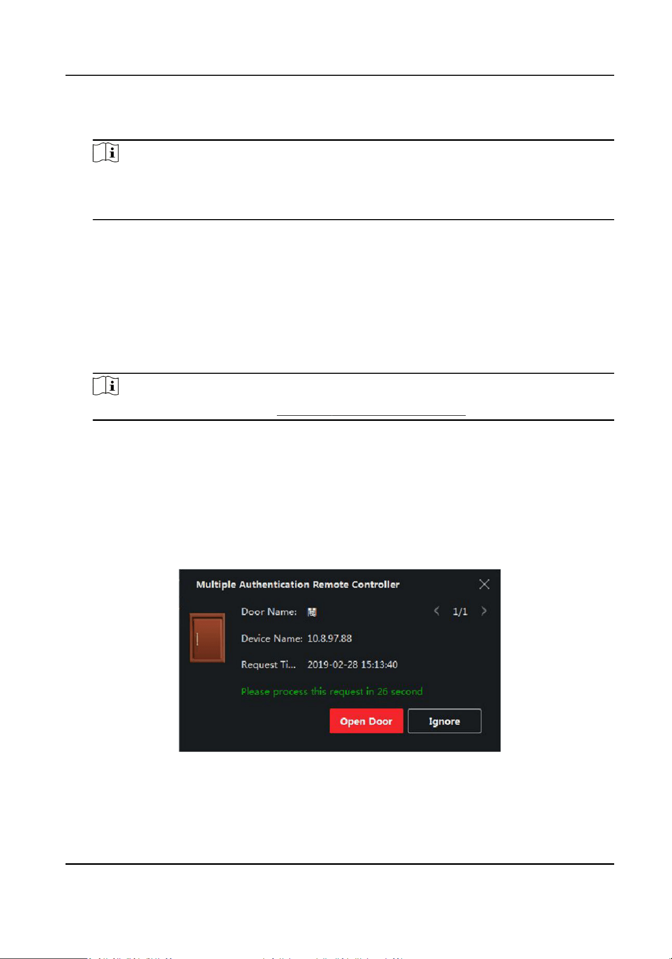
4) Select members(s) and card(s) in the Available list, and the selected member(s) and card(s)
will be added to the Selected list.
Note
Make sure you have issue card to the person.
Make sure you have set access group and apply the access group to the access control device
successfully.
5) Click Save.
6)
Oponal: Select the person/card group(s), and then click Delete to delete it(them).
7) Oponal: Select the person/card group(s), and then click Apply to re-apply access group that
failed to be applied previously to the access control device.
4.
Select an access control point (door) of selected device on the
le panel.
5.
Enter the maximum interval when entering password.
6.
Add an
authencaon group for the selected access control point.
1) Click Add on the Authencaon Groups panel.
2) Select a
congured template as the authencaon template from the drop-down list.
Note
For seng the template, refer to Congure Schedule and Template .
3) Select the authencaon type as Local Authencaon, Local Authencaon and Remotely
Open Door, or Local Authencaon and Super Password from the drop-down list.
Local
Authencaon
Authencaon by the access control device.
Local Authencaon and Remotely Open Door
Authencaon by the access control device and by the client. When the person swipes the
card on the device, a window will pop up. You can unlock the door via the client.
Figure 9-2 Remotely Open Door
DS-K281X Series Access Controller User Manual
55
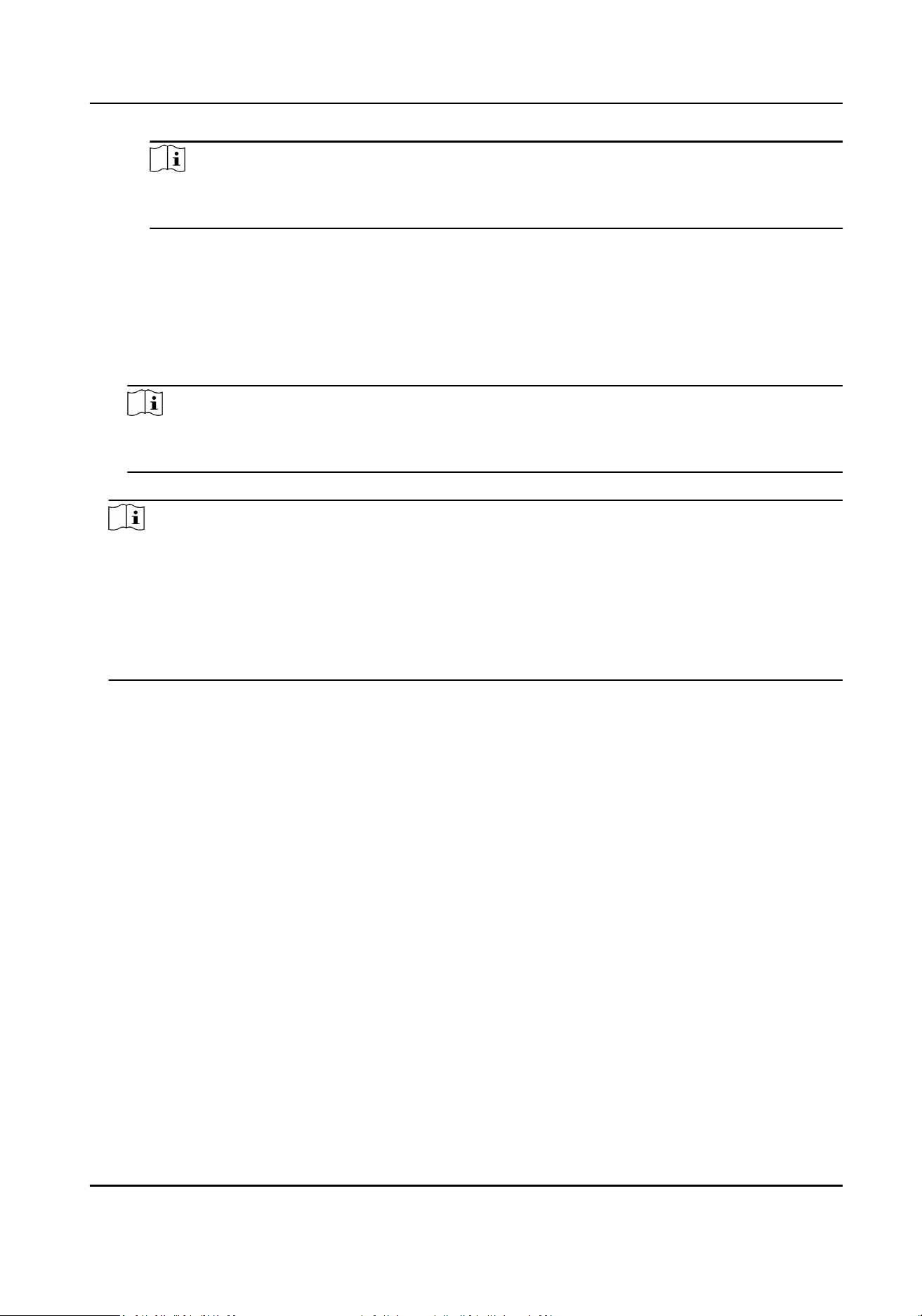
Note
You can check Oine Authencaon to enable the super password authencaon when
the access control device is disconnected with the client.
Local Authencaon and Super Password
Authencaon by the access control device and by the super password.
4) Select the added person/card group in the
le list below and it will be added to the Selected
list on the right as the authencaon group.
5) Click the added authencaon group in the right list to set authencaon mes in the Auth
Times column.
Note
The authencaon mes should be larger than 0 and smaller than the added personnel
quanty in the personnel group.
6) Click Save.
Note
●
For each access control point (door), up to four authencaon groups can be added.
●
For the authencaon group of which authencaon type is Local Authencaon, up to 8
person/card groups can be added to the authencaon group.
●
For the
authencaon group of which authencaon type is Local Authencaon and Super
Password or Local
Authencaon and Remotely Open Door, up to 7 person/card groups can
be added to the
authencaon group.
7.
Click Save.
9.7.6
Congure Card Reader Authencaon Mode and Schedule
You can set the passing rules for the card reader of the access control device according to your
actual needs.
Steps
1.
Click Access Control → Advanced Funcon → Authencaon to enter the authencaon mode
conguraon page.
2.
Select a card reader on the le to congure.
3.
Set card reader authencaon mode.
1) Click Conguraon.
DS-K281X Series Access Controller User Manual
56
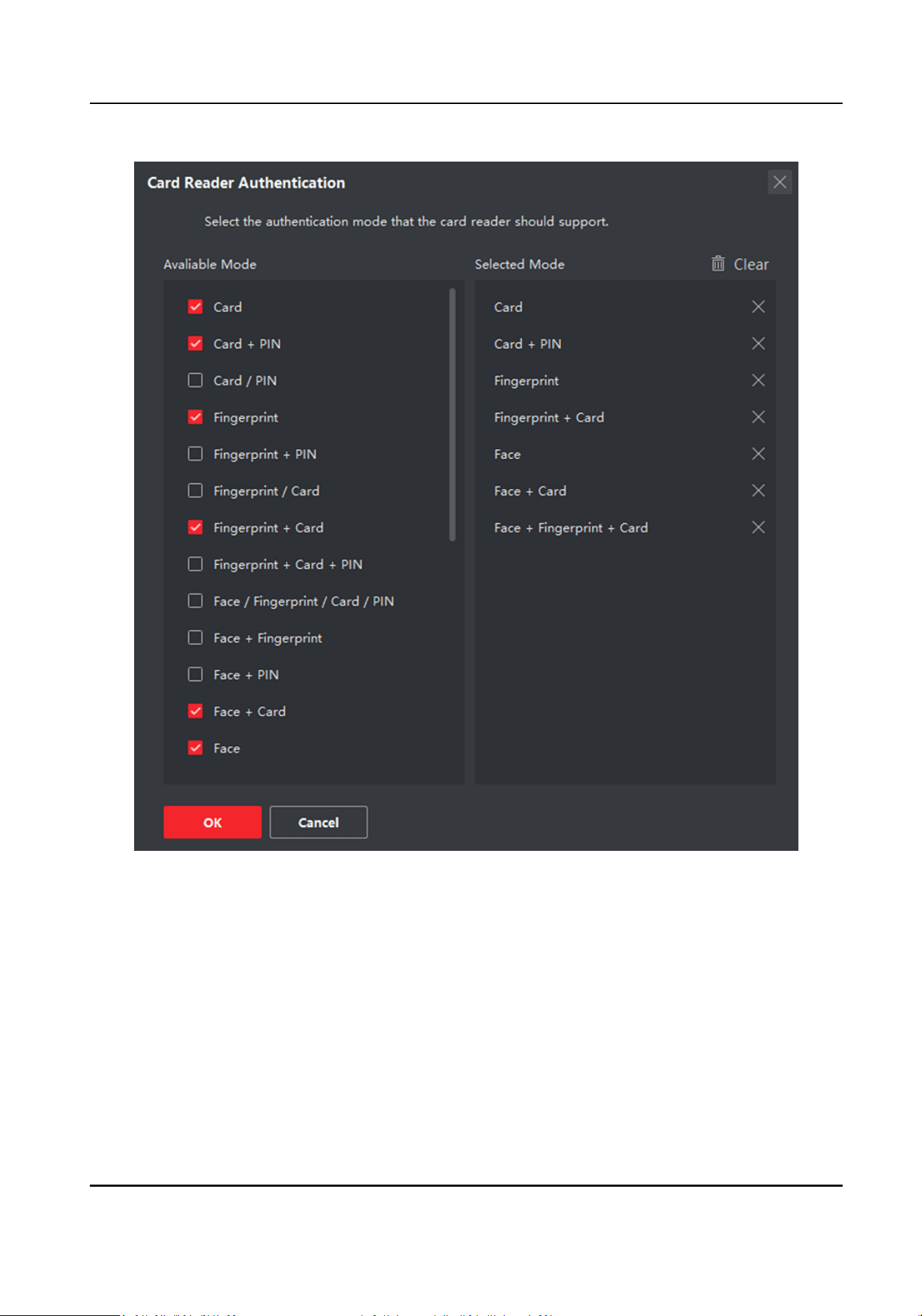
Figure 9-3 Select Card Reader Authencaon Mode
2) Check the modes in the Available Mode list and they will be added to the selected modes list.
3) Click OK.
Aer selecng the modes, the selected modes will display as icons with dierent color.
4.
Click the icon to select a card reader authencaon mode, and drag the cursor to draw a color
bar on the schedule, which means in that period of me, the card reader authencaon is valid.
5.
Repeat the above step to set other
me periods.
6.
Oponal: Select a congured day and click Copy to Week to copy the same sengs to the whole
week.
7.
Oponal: Click Copy to to copy the sengs to other card readers.
8.
Click Save.
DS-K281X Series Access Controller User Manual
57
9.7.7 Congure Device Parameters
Aer adding the access control device, you can congure the parameters of access control device,
access control points.
Congure Parameters for Access Control Device
Aer adding the access control device, you can congure its parameters, including overlaying user
informaon on picture, uploading pictures aer capturing, saving captured pictures, etc.
Before You Start
Add access control device to the client.
Steps
1.
Click Access Control → Advanced
Funcon → Device Parameters .
Note
If you can not nd Device Parameter in the Advanced Funcon list, hover the cursor on the
Advanced Funcon, and then Click to select the Device Parameter to be displayed.
2.
Select an access device to show its parameters on the right page.
3.
Turn the switch to ON to enable the corresponding
funcons.
Note
●
The displayed parameters may vary for dierent access control devices.
●
Some of the following parameters are not listed in the Basic Informaon page, click More to
edit the parameters.
Enable NFC
If enable the funcon, the device can recognize the NFC card. You can present NFC card on
the device.
Enable M1 Card
If enable the funcon, the device can recognize the M1 card. You can present M1 card on the
device.
Enable EM Card
If enable the
funcon, the device can recognize the EM card. You can present EM card on the
device.
Enable CPU Card
Reserved. If enable the funcon, the device can recognize the CPU card. You can present CPU
card on the device.
Enable ID Card
DS-K281X Series Access Controller User Manual
58

Reserved. If enable the funcon, the device can recognize the ID card. You can present ID
card on the device.
4.
Click OK.
5.
Oponal: Click Copy to, and then select the access control device(s) to copy the parameters in
the page to the selected device(s).
Congure Parameters for Door
Aer adding the access control device, you can congure its access point (door) parameters.
Steps
1.
Click Access Control → Advanced
Funcon → Device Parameter .
2.
Select an access control device on the le panel, and then click to show the doors or oors of
the selected device.
3.
Select a door or
oor to show its parameters on the right page.
4.
Edit the door or oor parameters.
Note
●
The displayed parameters may vary for dierent access control devices.
●
Some of the following parameters are not listed in the Basic Informaon page, click More to
edit the parameters.
Name
Edit the card reader name as desired.
Door Contact
You can set the door sensor as remaining closed or remaining open. Usually, it is remaining
closed.
Exit
Buon Type
You can set the exit buon as remaining closed or remaining open. Usually, it is remaining
open.
Open Duraon
The door contact can be enabled with appropriate delay aer person with extended accesss
needs swipes her/his card.
Door
Le Open Timeout Alarm
The alarm can be triggered if the door has not been closed in a congured me period. If it is
set as 0, no alarm will be triggered.
Super Password
The specic person can open the door by inpung the super password.
5.
Click Advanced to
congure advanced parameters.
Extended Open Duraon
DS-K281X Series Access Controller User Manual
59
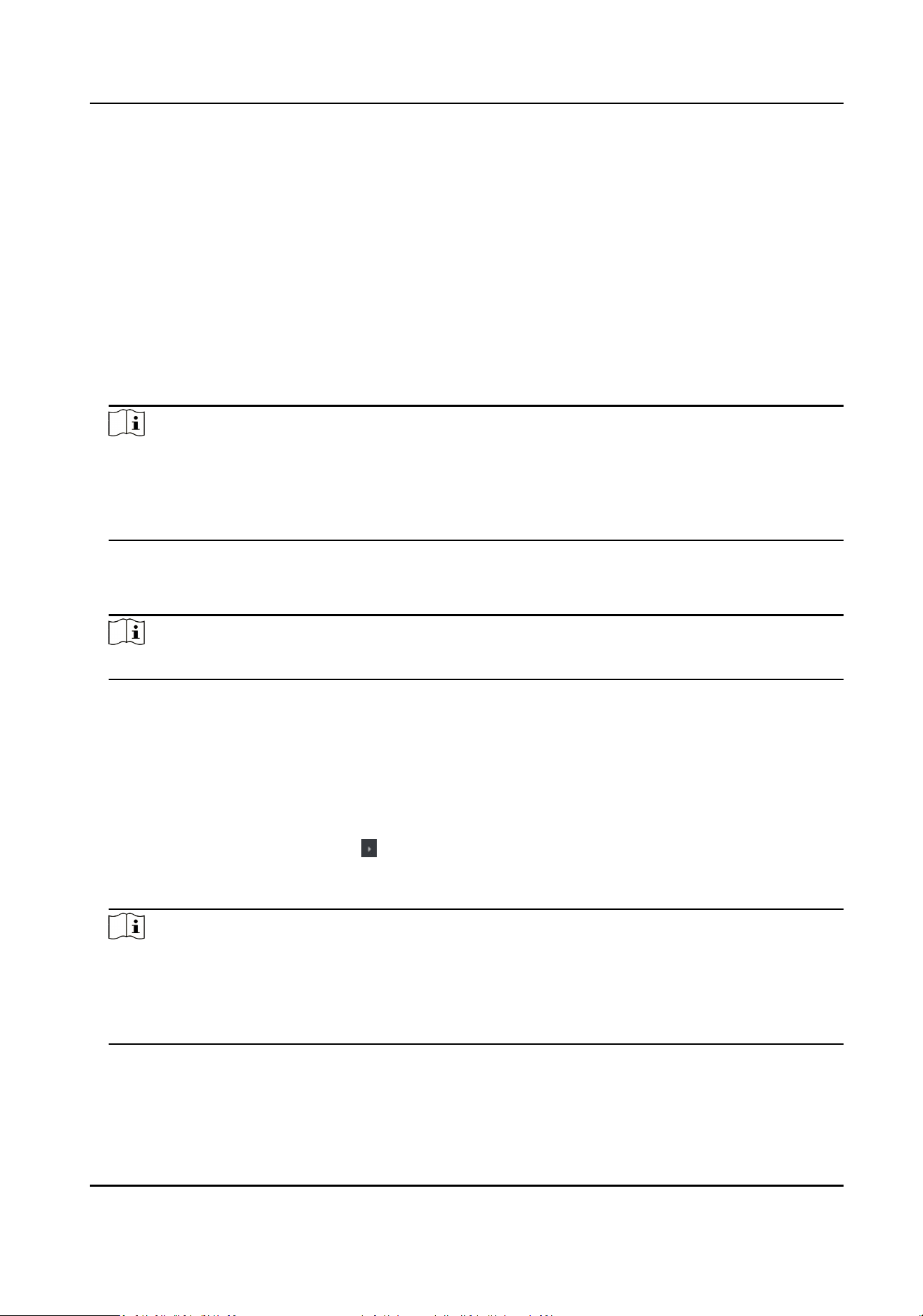
The door contact can be enabled with appropriate delay aer person with extended accesss
needs swipes her/his card.
Duress Code
The door can open by inpung the duress code when there is duress. At the same me, the
client can report the duress event.
Enable Locking Door when Door Closed
The door can be locked once it is closed even if the Door Locked Time is not reached.
Dismiss Code
Create a dismiss code which can be used to stop the buzzer of the card reader (by entering
the dismiss code on the keypad).
Note
●
The duress code and super password should be dierent.
●
The duress code and super password should be dierent from the authencaon password.
●
The length of duress code and super password is according the device, usually it should
contains 4 to 8 digits.
6.
Click OK.
7.
Oponal: Click Copy to , and then select the door to copy the parameters in the page to the
selected doors.
Note
The door or oor's status duraon sengs will be copied to the selected door as well.
Congure Parameters for Card Reader
Aer adding the access control device, you can congure its card reader parameters.
Steps
1.
Click Access Control → Advanced Funcon → Device Parameter .
2.
In the device list on the le, click to expand the door, select a card reader and you can edit the
card reader's parameters on the right.
3.
Edit the card reader basic parameters in the Basic
Informaon page.
Note
●
The displayed parameters may vary for dierent access control devices. There are part of
parameters listed as follows. Refer to the user manual of the device for more details.
●
Some of the following parameters are not listed in the Basic Informaon page, click More to
edit the parameters.
Name
Edit the card reader name as desired.
DS-K281X Series Access Controller User Manual
60

Card Authencaon Interval
If the interval between card swiping of the same card is less than the set value, the card
swiping is invalid. You can set it as 0 to 255.
Enable Failed Aempts Limit of Authencaon
Enable to report alarm when the card reading aempts reach the set value.
Card Reader Type/Card Reader Descripon
Get card reader type and descripon. They are read-only.
4.
Click Advanced and you can congure more parameters.
Enable Card Reader
Enable the funcon and you can operate the funcons below on the card reader.
OK LED Polarity/Error LED Polarity/Buzzer Polarity
Set OK LED Polarity/Error LED Polarity/Buzzer LED Polarity of main board according to the
card reader parameters. Generally, adopts the default
sengs.
Buzzer Polarity
Set Buzzer Polarity of main board according to the card reader parameters. Generally, adopts
the default sengs.
Buzzing Time
Set the card reader buzzing me. The available me ranges from 0 to 5,999s. 0 represents
connuous buzzing.
Max. Interval When Entering PWD
When you inpung the password on the card reader, if the interval between pressing two
digits is larger than the set value, the digits you pressed before will be cleared automacally.
Tampering Detecon
Enable the an-tamper detecon for the card reader.
Communicate with Controller Every
When the access control device cannot connect with the card reader for longer than the set
me, the card reader will turn oine automacally.
Fingerprint Recognion Level
Select the ngerprint recognion level from the drop-down list.
5.
Click OK.
6.
Oponal: Click Copy to, and then select the card reader(s) to copy the parameters in the page to
the selected card reader(s).
Congure
Parameters for Alarm Output
Aer adding the access control device, if the device links to alarm outputs, you can congure the
parameters.
DS-K281X Series Access Controller User Manual
61

Before You Start
Add access control device to the client, and make sure the device supports alarm output.
Steps
1.
Click Access Control → Advanced
Funcon → Device Parameter to enter access control
parameter conguraon page.
2.
In the device list on the le, click to expand the door, select an alarm input and you can edit
the alarm input's parameters on the right.
3.
Set the alarm output parameters.
Name
Edit the card reader name as desired.
Alarm Output
Acve Time
How long the alarm output will last aer triggered.
4.
Click OK.
5.
Oponal: Set the switch on the upper right corner to ON to trigger the alarm output.
9.7.8
Congure Device Parameters
Aer adding the access control device, you can set its parameters such as network parameters.
Enable M1 Card
Encrypon
M1 card encrypon can improve the security level of authencaon.
Steps
Note
The funcon should be supported by the access control device and the card reader.
1.
Enter the Access Control module.
2.
On the navigaon bar on the le, enter Advanced Funcon → More Parameters .
3.
Select an access control device in the device list and click M1 Card
Encrypon to enter the M1
Card Encrypon page.
4.
Set the switch to on to enable the M1 card encrypon funcon.
5.
Set the sector ID.
The sector ID ranges from 1 to 100.
6.
Click Save to save the
sengs.
DS-K281X Series Access Controller User Manual
62
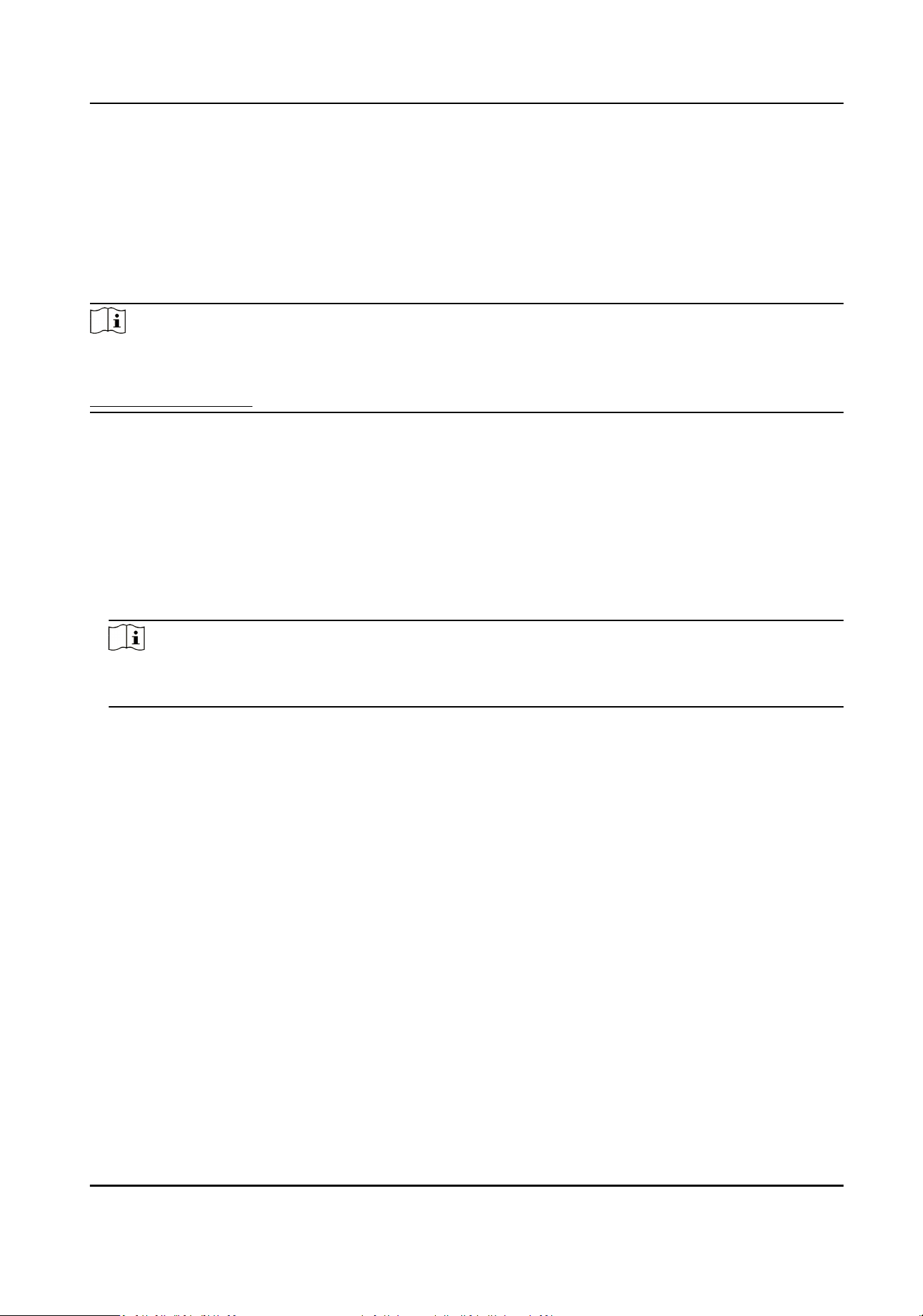
9.8 Door Control
In Monitoring module, you can view the real-me status of the doors managed by the added
access control device. You can also control the doors such as open/close the door, or remain the
door open/closed via the client remotely. The real-me access event are displayed in this module.
You can view the access details and person details.
Note
For the user with door control permission, the user can enter the Monitoring module and control
the door. Or the icons used for control will not show. For seng the user permission, refer to
Person Management .
9.8.1 Control Door Status
You can control the status for a single door, including opening door, closing door, remaining the
door open, and remaining the door closed.
Steps
1.
Click Monitoring to enter the status monitoring page.
2.
Select an access point group on the upper-right corner.
Note
For managing the access point group, refer to Group Management in the user manual of the
client soware.
The doors in the selected access control group will display.
3.
Click a door icon to select a door, or press Ctrl and select
mulple doors.
4.
Click the following buons to control the door.
Open Door
When the door is locked, unlock it and it will be open for once.
Aer the open duraon, the
door will be closed and locked again automacally.
Close Door
When the door is unlocked, lock it and it will be closed. The person who has the access
authorizaon can access the door with credenals.
Remain Open
The door will be unlocked (no maer closed or open). All the persons can access the door
with no credenals required.
Remain Closed
The door will be closed and locked. No person can access the door even if he/she has the
authorized credenals, except the super users.
DS-K281X Series Access Controller User Manual
63

Capture
Capture a picture manually.
Note
The Capture buon is available when the device supports capture funcon. The picture is
saved in the PC running the client. For seng the saving path, refer to Set File Saving Path in
the user manual of the client soware.
Result
The icon of the doors will change in real-me according to the operaon if the operaon is
succeeded.
9.8.2 Check Real-Time Access Records
The access records will display in real me, including card swiping records, ngerprint comparison
records, etc. You can view the person informaon and view the picture captured during access.
Steps
1.
Click Monitoring and select a group from the drop-down list on the upper-right corner.
The access records triggered at the doors in the selected group will display in real
me. You can
view the details of the records, including card No., person name, organizaon, event me, etc.
2.
Oponal: Check the event type and event status so that these events will show in the list if the
events are detected. The events of unchecked type or status will not be displayed in the list.
3.
Oponal: Check Show Latest Event and the latest access record will be selected and displayed at
the top of the record list.
4.
Oponal: Click the event to view the accessed person details, including person pictures
(captured picture and
prole), person No., person name, organizaon, phone, contact address,
etc.
Note
You can double click the captured picture to enlarge it to view the details.
5.
Oponal: Right click on the column name of the access event table to show or hide the column
according to actual needs.
DS-K281X Series Access Controller User Manual
64
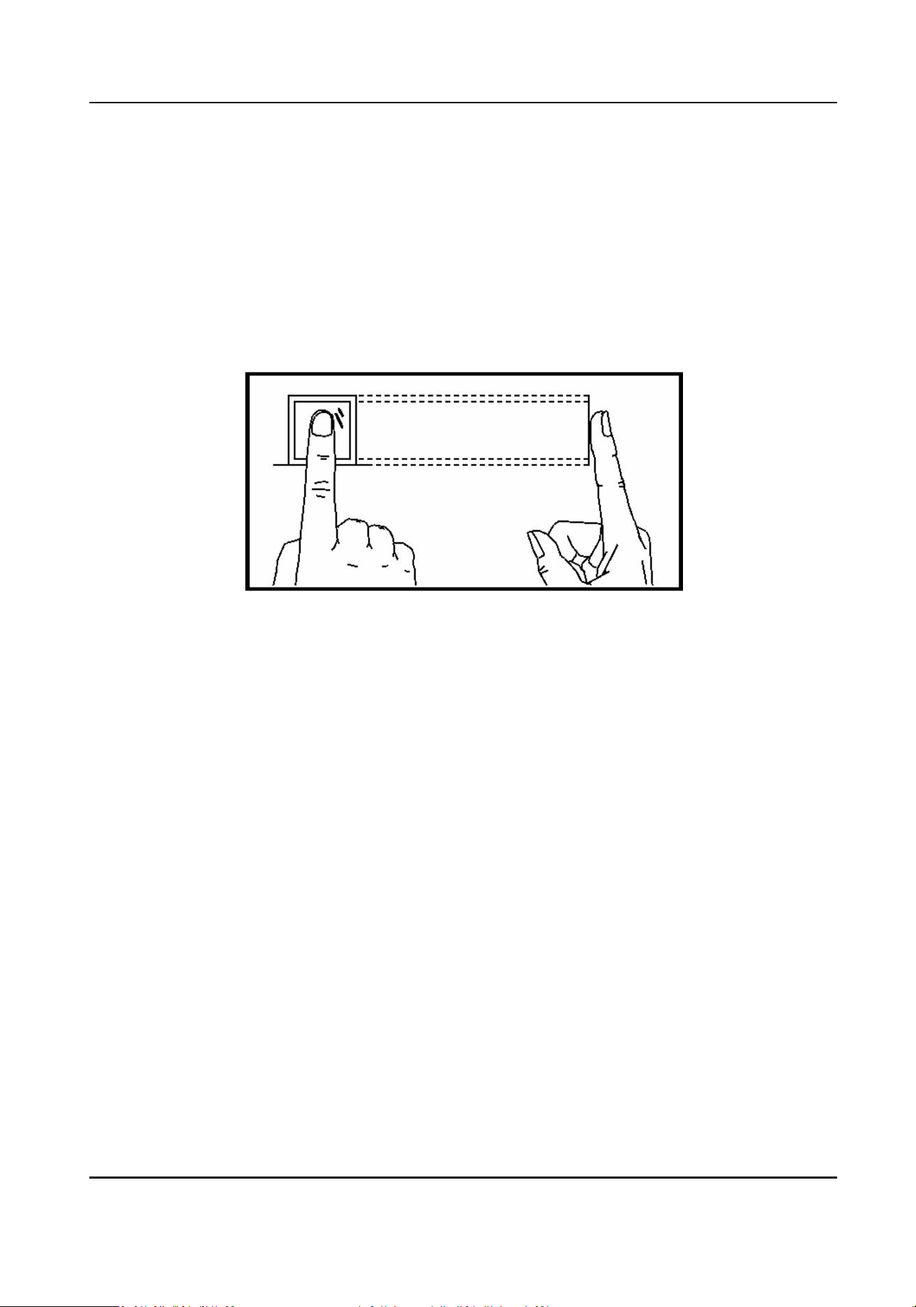
Appendix A. Tips for Scanning Fingerprint
Recommended Finger
Forenger, middle nger or the third nger.
Correct Scanning
The gure displayed below is the correct way to scan your nger:
You should press your nger on the scanner horizontally. The center of your scanned nger should
align with the scanner center.
Incorrect Scanning
The gures of scanning ngerprint displayed below are incorrect:
DS-K281X Series Access Controller User Manual
65
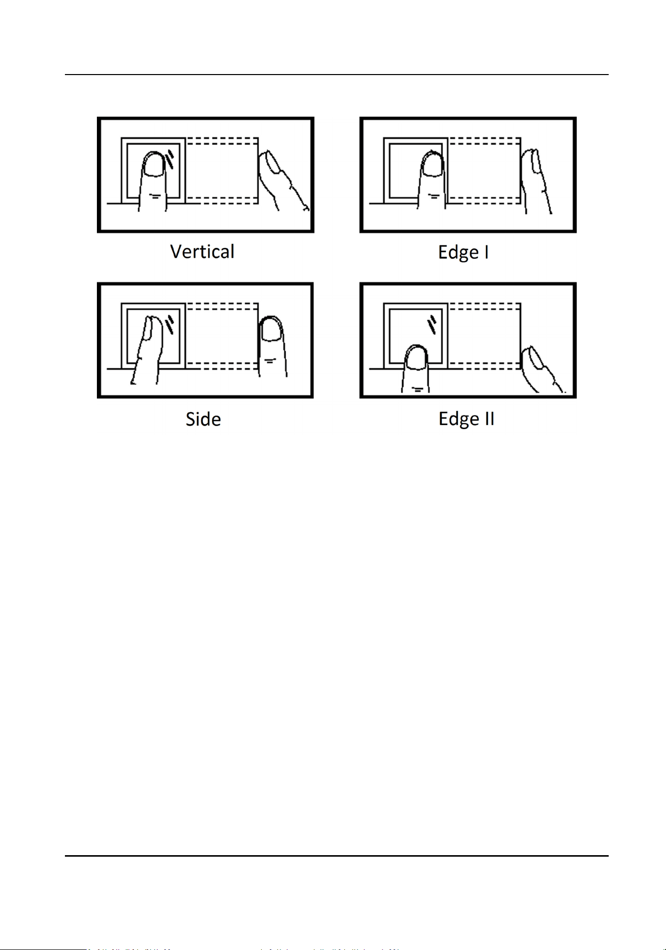
Environment
The scanner should avoid direct sun light, high temperature, humid condions and rain.
When it is dry, the scanner may not recognize your
ngerprint successfully. You can blow your
nger and scan again.
Others
If your ngerprint is shallow, or it is hard to scan your ngerprint, we recommend you to use other
authencaon methods.
If you have injuries on the scanned nger, the scanner may not recognize. You can change another
nger and try again.
DS-K281X Series Access Controller User Manual
66
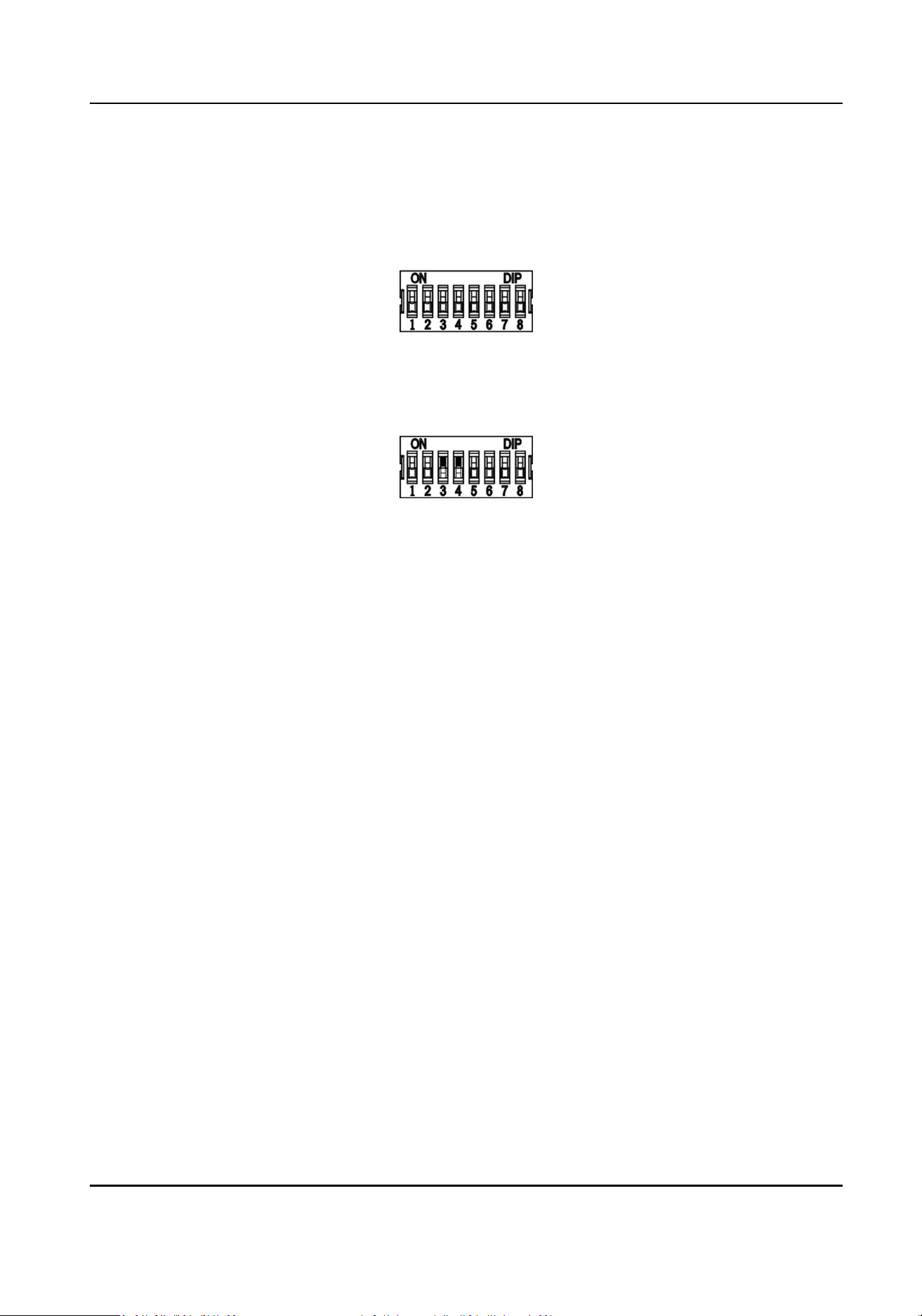
Appendix B. DIP Switch Descripon
No.1 to No 8 is from the low bit to the high bit.
When the switch is towards ON, it means the switch is enabled, otherwise, the switch is o. If you
set the DIP switch like the gure displayed below, its binary value is 00001100, and its decimal
value is 12.
DS-K281X Series Access Controller User Manual
67

Appendix C. Custom Wiegand Rule Descripons
Take Wiegand 44 as an example, the seng values in the Custom Wiegand tab are as follows:
Custom Wiegand
Name
Wiegand 44
Total Length 44
Transformaon Rule
(Decimal Digit)
byFormatRule[4]=[1][4][0][0]
Parity Mode XOR Parity
Odd Parity Start Bit Length
Even Parity Start Bit Length
XOR Parity Start Bit 0 Length per Group 4 Total Length 40
Card ID Start Bit 0 Length 32 Decimal Digit 10
Site Code Start Bit Length Decimal Digit
OEM Start Bit Length Decimal Digit
Manufacturer Code
Start Bit
32 Length 8 Decimal Digit 3
Wiegand Data
Wiegand Data = Valid Data + Parity Data
Total Length
Wiegand data length.
Transportaon
Rule
4 bytes. Display the combinaon types of valid data. The example displays the combinaon of Card
ID and Manufacturer Code. The valid data can be single rule, or
combinaon of mulple rules.
Parity Mode
Valid parity for Wiegand data. You can select either odd parity or even parity.
Odd Parity Start Bit, and Length
If you select Odd Parity, these items are available. If the odd parity start bit is 1, and the length is
12, then the system will start odd parity calculaon from bit 1. It will calculate 12 bits. The result
will be in bit 0. (Bit 0 is the
rst bit.)
DS-K281X Series Access Controller User Manual
68

Even Parity Start Bit, and Length
If you select Even Parity, these items are available. If the even parity start bit is 12, and the length is
12, then the system will start even parity calculaon from bit 12. It will calculate 12 bits. The result
will be in the last bit.
XOR Parity Start Bit, Length per Group, and Total Length
If you select XOR Parity, these items are available. Depending on the table displayed above, the
start bit is 0, the length per group is 4, and the total length is 40. It means that the system will
calculate from bit 0, calculate every 4 bit, and calculate 40 bits in total (10 groups in total). The
result will be in the last 4 bits. (The result length is the same as the length per group.)
Card ID Start Bit, Length, and Decimal Digit
If you use the transformaon rule, these items are available. Depending on the table displayed
above, the card ID start bit is 0, the length is 32, and the decimal digit is 10. It represents that from
bit 0, there are 32 bits represent the card ID. (The length here is calculated by bit.) And the decimal
digit length is 10 bits.
Site Code Start Bit, Length, and Decimal Digit
If you use the transformaon rule, these items are available. For detailed informaon, see the
explanaon of the card ID.
OEM Start Bit, Length, and Decimal Digit
If you use the transformaon rule, these items are available. For detailed informaon, see the
explanaon of the card ID.
Manufacturer Code Start Bit, Length, and Decimal Digit
If you use the transformaon rule, these items are available. Depending on the table displayed
above, the manufacturer code start bit is 32, length is 8, and decimal digit is 3. It represents that
from bit 32, there are 8 bits are manufacturer code. (The length here is calculated by bit.) And the
decimal length is 3.
DS-K281X Series Access Controller User Manual
69
Appendix D. Communicaon Matrix and Device
Command
Communicaon Matrix
Scan the following QR code to get the device communicaon matrix.
Note that the matrix contains all
communicaon ports of Hikvision access control and video
intercom devices.
Figure D-1 QR Code of Communicaon Matrix
Device Command
Scan the following QR code to get the device common serial port commands.
Note that the command list contains all commonly used serial ports commands for all Hikvision
access control and video intercom devices.
Figure D-2 Device Command
DS-K281X Series Access Controller User Manual
70

UD31244B-A