Jeep Wrangler
i509-WRA-JK 20220404v1
1/22
Jeep Wrangler
i509-WRA-JK
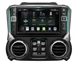
9” Restyle Installation Manual
Model: Wrangler JK
Model Year: 2011-2018
Note:
Design and specifications are subject to change without notice for improvement.
To Ensure Safe Use, Always Follow These Precautions
The installation of this product requires specialized skills and experience. We recommend that you have the
product installed by an Alpine authorized dealer.
Before you use this product, be sure to carefully read this installation manual and the separate user's manual
so that you can use the product correctly. Alpine Electronics bears no responsibility for problems that arise as
a result of failure to follow the instructions in the manuals.
This manual includes a number of symbols that are intended to help you use the product safely, to prevent
harm to you and others, and to protect against damage to property. These symbols and their meanings are
listed below. Make sure you fully understand these symbols before you begin reading the main text.
Explanations of Injury and Damage That May Result from Incorrect Use
Warning
Ignoring the content marked by this indication and using the product incorrectly is
expected to lead to death or serious injury.
Caution
Ignoring the content marked by this indication and using the product incorrectly is only
expected to lead to injury or property damage.
Jeep
Model Year
Wrangler JK 2011 - 2018
* The specified vehicles have been tested and have met compatibility specs at the time of testing. Compatibility is
not guaranteed if the manufacturer has made production changes to the listed vehicles above.
Warning: Before you begin wiring, remove the ground wire from the negative
terminal of the battery. Failing to do so can lead to electric shock, injury or damage
to equipment.
Introduction
Congratulations on purchasing the i509-WRA-JK. This installation manual is designed to take you through the
step-by-step installation of the i509-WRA-JK into a 2011-2018 Jeep Wrangler. Please familiarize yourself with
the owners manual and if you still have additional questions please call 1-800-TECH-101.
Jeep Wrangler
i509-WRA-JK 20220404v1
2/22
Forbidden
Indicates actions that are
forbidden (must not be
performed)
Forbidden
Indicates that disassembly is
forbidden.
Mandatory
Indicates actions that are
mandatory (must be performed)
Marks content that should receive
your full attention.
Warning
Do not disassemble or modify the product.
Doing so could lead to an accident, fire, or
electric shock.
Forbidden
Store screws and other small objects where
children cannot reach them. If one of thse
small objects is swallowed, consult with a
doctor immediately.
When replacing fuses be sure to
use the fuses with the specified current
rating. Failing to do so could lead to
an accident or fire.
Forbidden
Only connect the product to a 12 VDC negative
ground car. Failing to do so could lead to an
accident or fire.
Mandatory
Before you begin wiring, remove the ground
wire from the negative terminal of the battery.
Failing to do so could lead to electric shock or
injury.
Do not cut the insulation on a cord and take
power from another device. Doing so could
lead to fire or electric shock.
Forbidden
Do not install the product in a location where
it willl obstruct the driver’s forward view;
interfere with the operation of the steering
wheel, gear shift, or the like; or pose a threat
to passengers. Doing so could lead to an ac-
cident or injury.
Forbidden
When making a hole in the vehicle body, be
careful to avoid damaging pipes, the fuel tank,
electrical wiring, and the like. This kind of
damage could lead to an accident or fire.
When installing and grounding the product, do
not use any of the bolts or nuts of the steering
wheel, brakes, fuel tank, or the like. Doing so
could make the brakes stop working or could
lead to fire.
Forbidden
Do not install athe product near the passen-
ger-side airbag. Doing so could interfere with
the operation of the airbag and lead to an
accident or injury.
Forbidden
Bundle cords so that they don’t interfere with
driving. Wrapping cords around the steer-
ing wheel, gearshift, brake pedal, or the like
could lead to an accident or damage equip-
ment.
Caution
Connect the product properly according to the
instructions. Failing to do so could lead to fire
or an accident.
Forbidden
Do not sandwich cords between the seat
railing or allow them to touch protrusions. Re-
sulting breaks or shorts could lead to electric
shock or fire.
Do not block vents or heat sinks. Doing so
could lead to fire or damage equipment.
Use the accessories according to the instruc-
tions, and attach them securely. Failing to
do so could lead to an accident or damage
equipment.
Forbidden
Do not install the product where it may be ex-
posed to water or in a place with high levels
of humidity or dust. Doing so could lead to fire
or damage equipment.
Forbidden
The installation and wiring of this product re-
quires specialized skills and experience. Have
the product installed by an Alpine authorized
dealer.
Types of Precautions
Mandatory
Jeep Wrangler
i509-WRA-JK 20220404v1
3/22
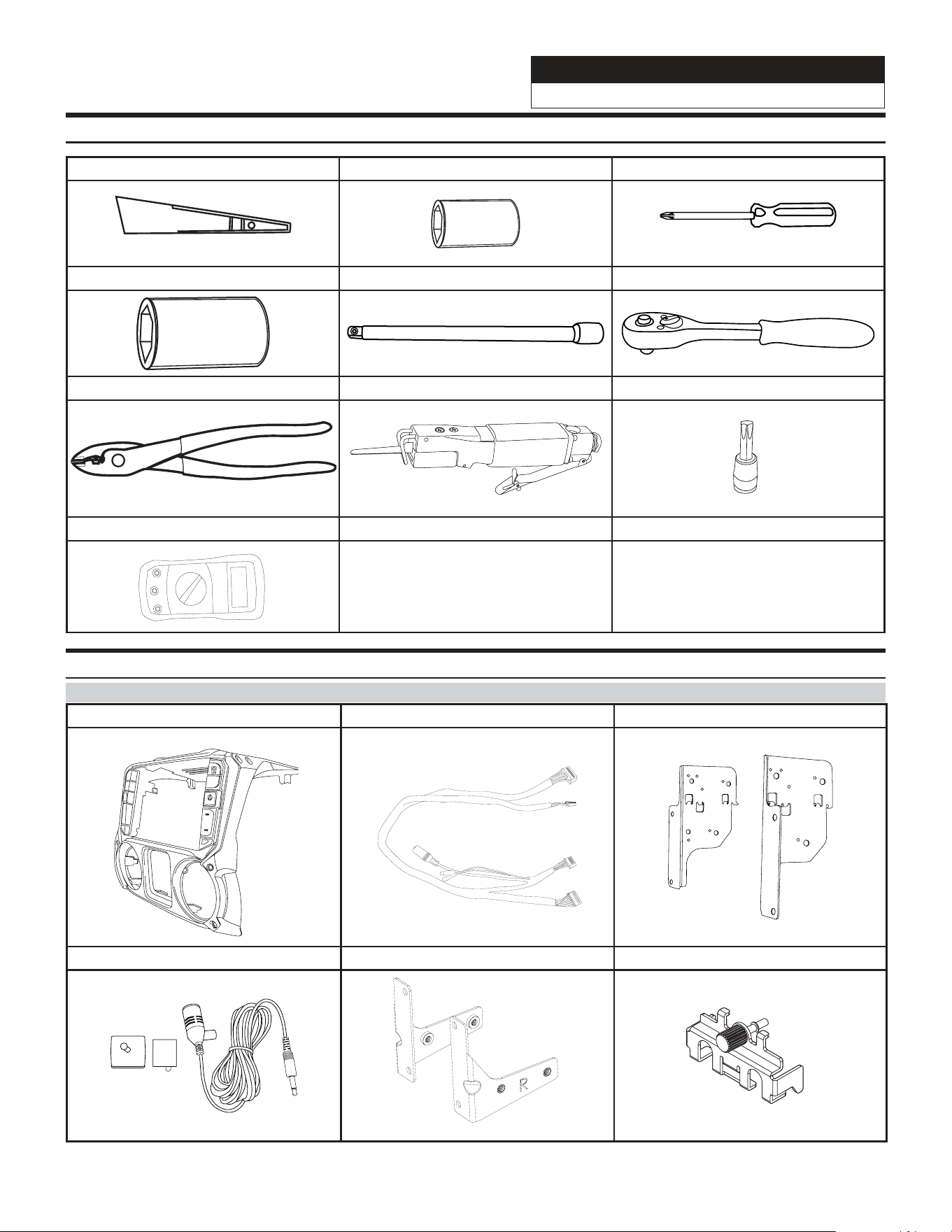
Tools Required
Panel Removing Tool 7mm Sockets #2 Phillips Screwdriver
10mm Sockets Extension Ratchet
Wire Cutters Air Saw T20 Torx
Digital Multimeter
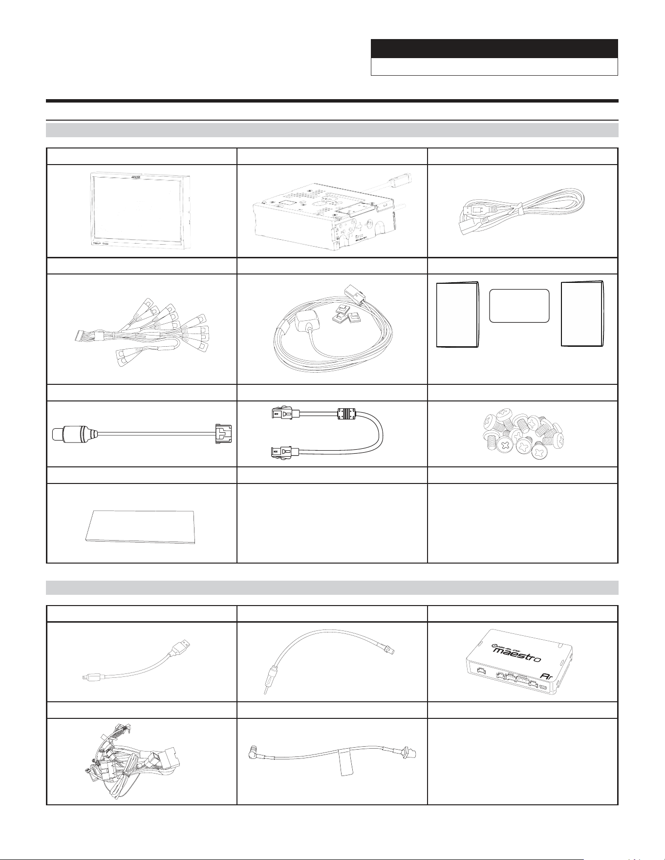
Accessory List
Installation Kit Parts
i509-WRA-JK Radio Dash Bezel Display Power/Key Harness Side Mounting Brackets
MENU
Microphone Display Mounting Brackets Source Unit HDMI Bracket
Jeep Wrangler
i509-WRA-JK 20220404v1
4/22
Accessory List
Head Unit Box Parts (i509)
i509 Display Unit i509 Source Unit USB Extension Cable
AUX/Pre Out Harness GPS Antenna Documents
Alpine
Registration Card
QRG Navigation
OM QR Card
Direct Camera Adapter Display Cable
Screws (12pcs)
Anti-Vibration Foam
iDatalink Maestro Box Parts (ALP-MRR4/ALP-HRN-WRA5)
Maestro Flashing Cable Antenna Adapter iDatalink Maestro Module
Main Harness SAT Radio Antenna Adapter
Jeep Wrangler
i509-WRA-JK 20220404v1
5/22
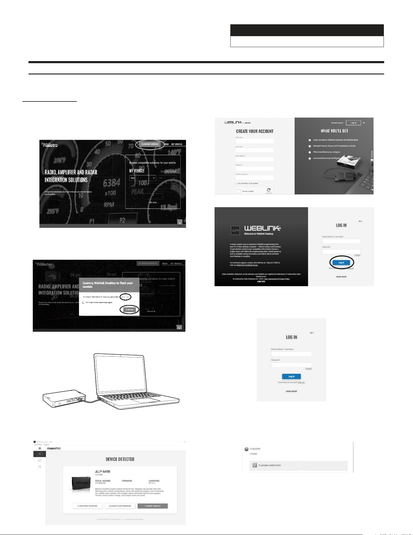
Programming the iDatalink Maestro Module
1 INSTALL THE WEBLINK PLUG-IN
Go to:
idatalinkmaestro.com and follow the installation steps. The
Maestro module must be programmed specifically for each vehicle
and radio. Take care to enter the correct vehicle information,
factory options, head unit model, and head unit serial number.
The head units serial number is an alphanumeric value which is
found on the head units label, underneath the bar code.
If the plugin is already installed, Click "Continue" and follow the
prompts to open. If Plug in is not installed Click "Get it now" and
follow prompts to downlaod and install the plug-in
3 CONNECT YOUR MAESTRO MODULE
Use your Maestro module to connect to your PC.
5 PROGRAM YOUR MODULE
Follow the programming steps for your vehicle.
2 REGISTER A WEBLINK ACCOUNT
Go to:
Sign Up and complete the registration process.
A conrmation email will be sent to you requiring validation.
For existing customers, click log in.
4 LOG INTO WEBLINK
Go to:
Enter your username and password, then click OK.
6 Once Programing is complete “FLASHING
COMPLETED!” will be displayed.
Proceed to the next page to complete installation.
NOTE: If serial number is invalid, Call ADS at
1-866-427-2999 with the serial number.
Jeep Wrangler
i509-WRA-JK 20220404v1
6/22
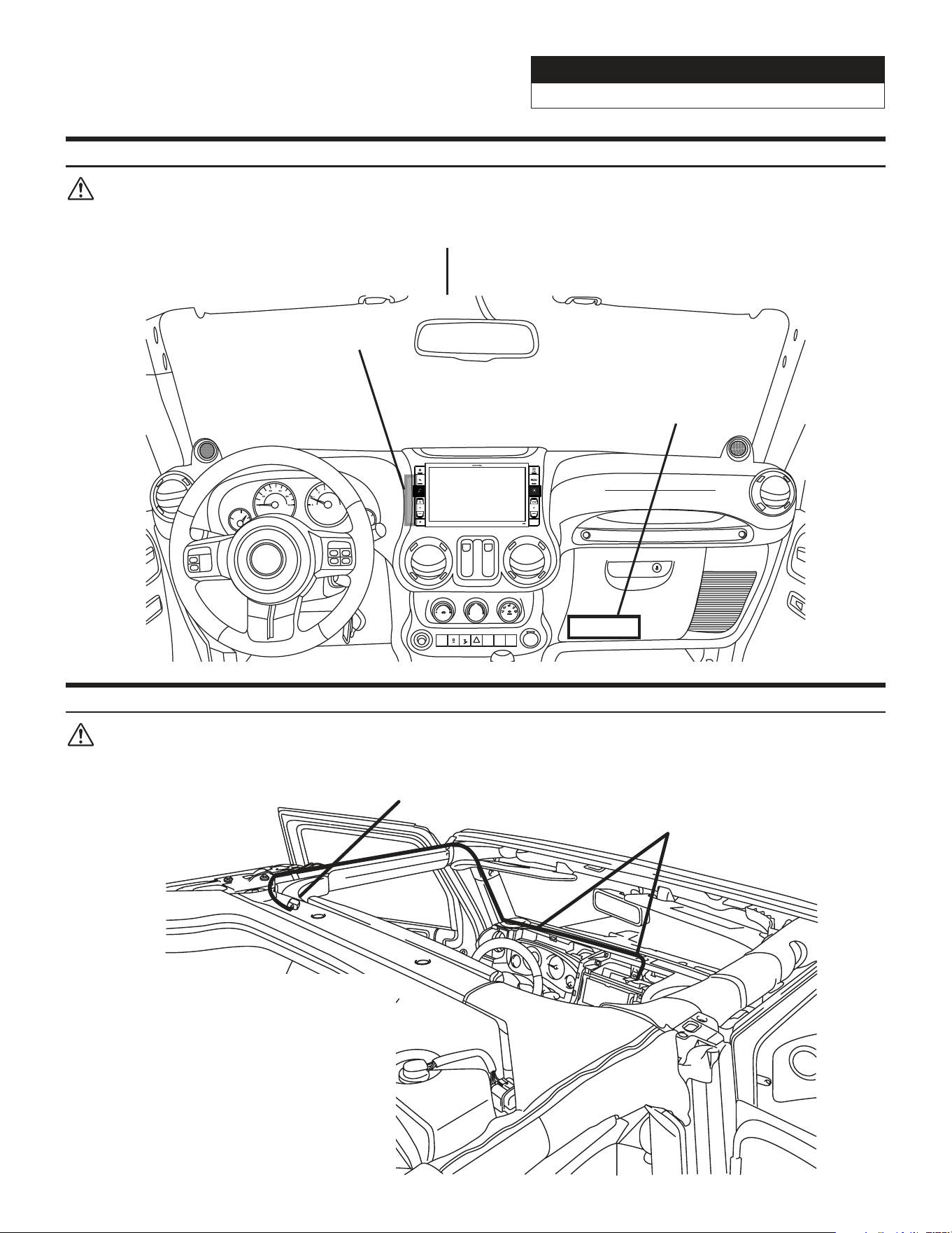
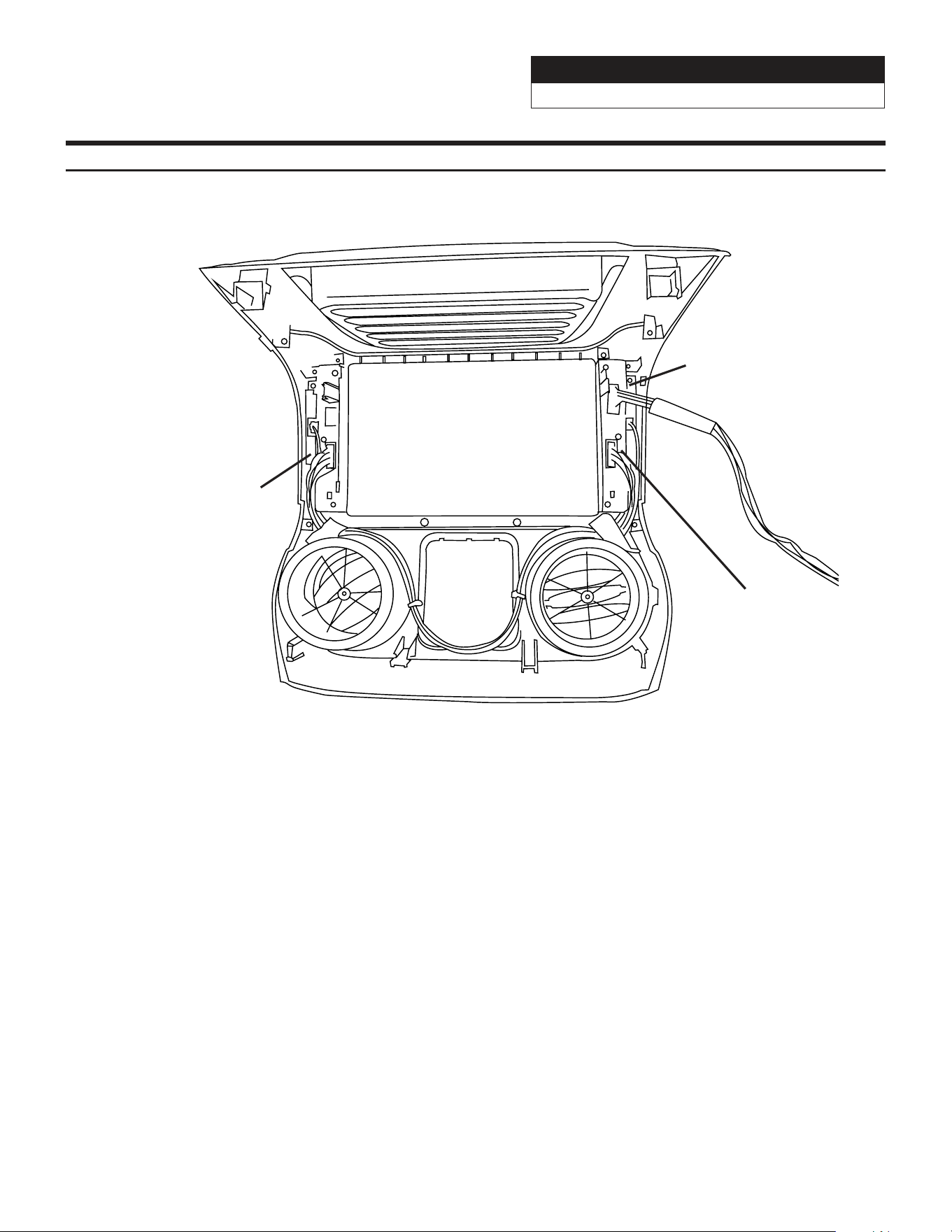
Component Locations
IMPORTANT: Follow the recommended component location shown below. Failure to do so, will result in poor
GPS performance.
Jeep
Jeep SINCE 1941
Add-on Microphone
iDatalink Maestro Module
SiriusXM Tuner
(Sold Separately)
GPS Antenna Installation
IMPORTANT: Follow the GPS antenna installation procedure shown below. Failure to do so will result in poor
GPS performance for CarPlay, Android Auto, and Navigation.
Wire Hook
GPS Antenna
Peel the plastic layer
off from the double
side tape of the GPS
antenna and place the
GPS antenna on top of
the driver side roof
frame. T20 Torx to
remove the visor.
Jeep Wrangler
i509-WRA-JK 20220404v1
7/22
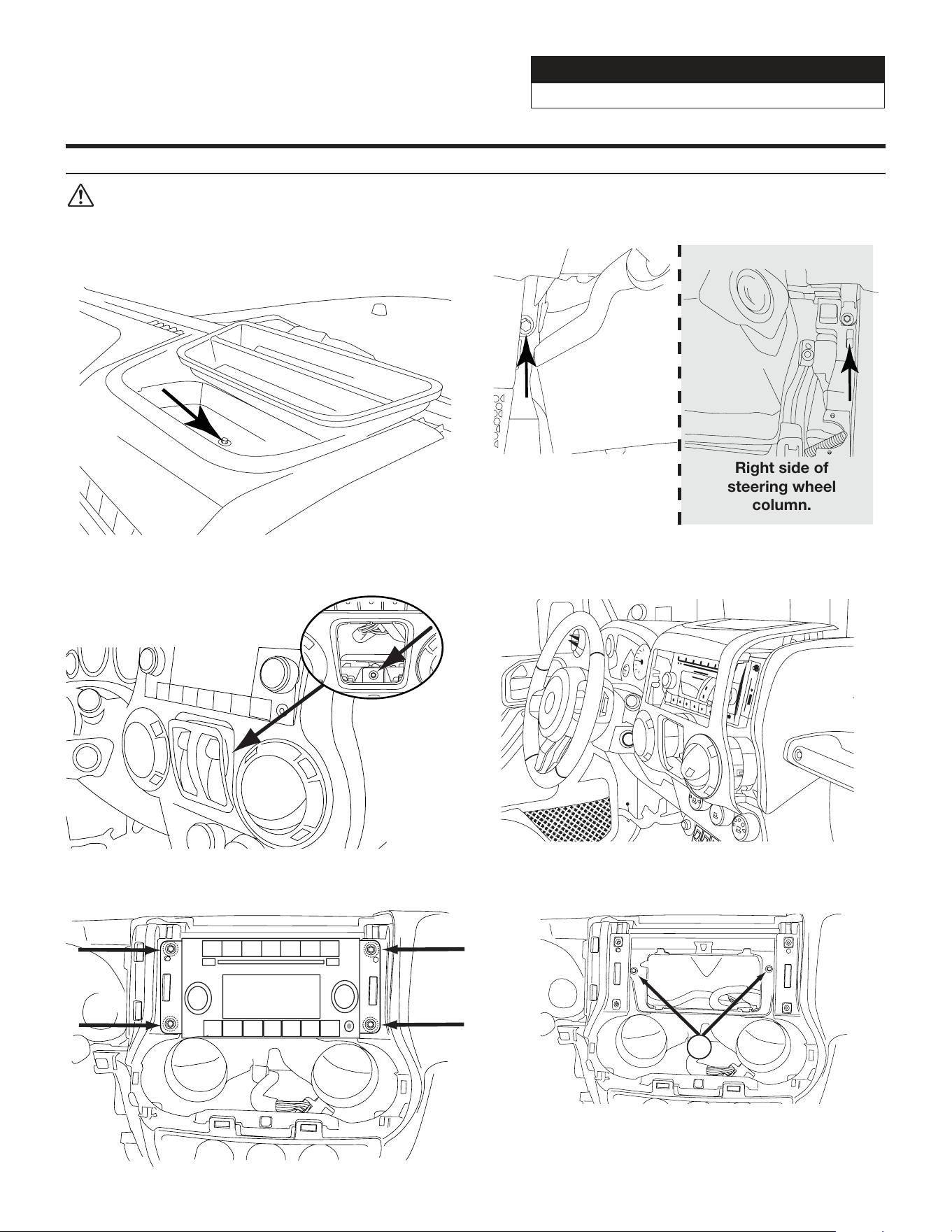
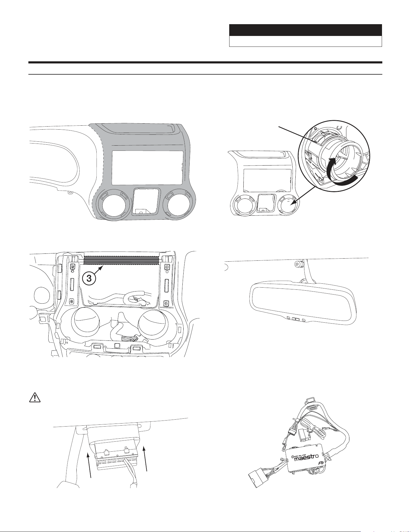
Factory Unit Disassembly Process
DISCONNECT THE BATTERY BEFORE
CONTINUING. FAILURE TO DO SO WILL
DISABLE MANY FEATURES.
1 Remove the rubber cover from the top center
storage area and extract (1) 7mm screw.
3 Remove the window switch pod using a panel
removing tool and extract (1) 7mm screw.
5 Extract (4) 7 mm screws and remove the factory
radio.
2 Remove the knee cover panel and extract (2) 7mm
screws located to the right and left sides of the
steering wheel column.
Right side of
steering wheel
column.
Left side of
steering wheel
column.
4 Remove the dash panel.
6 Extract (2) 7 mm screws from the factory radio
bracket and remove it.
2
Jeep Wrangler
i509-WRA-JK 20220404v1
8/22
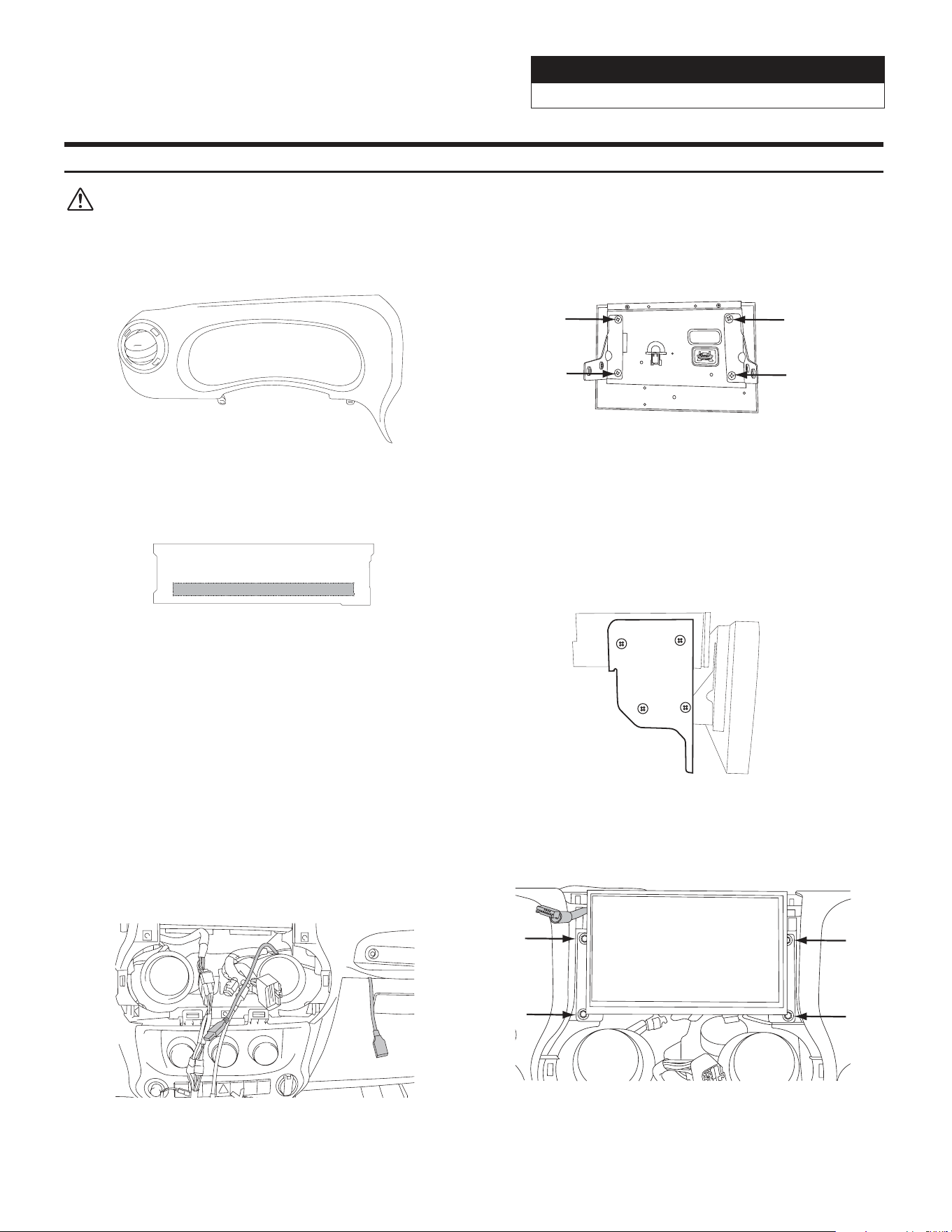
Installation Instructions
2 Remove the vents from the radio section on the
OEM dash panel by pressing down on the lock tab
and turning right. Mount vents on to the i509-WRA-
JK bezel.
Lock tab
Rear view
4 Mount the microphone as illustrated and run the
cable to the radio cavity.
6 Attach the Maestro to the main harness.
*See page 13 for more details.
1 The factory dash panel needs to be trimmed to
allow the new i509-WRA-JK bezel to fit into place.
Remove the highlighted area by cutting along the
dashed line.
3 Use a cutting tool to trim the highlighted area
shown below.
5 Plug the OBDII connector on to the OBDII port
below the driver side dash and run the extension to
the radio cavity.
Avoid any sharp edges or interfering with
any safety equipment.
Jeep Wrangler
i509-WRA-JK 20220404v1
9/22
Installation Instructions
2 Put monitor face down on a soft, scratch free
surface and attach Display Monitor Brackets using
(4) 8mm screws (provided). Plug in the Display
Cable and Display Power Harness.
4 Attach the display and source unit with the 8mm
screws (supplied) as shown below.
Route the display cable and power harness
from the display to the source unit and
plug into the W. Remote and Display Out.
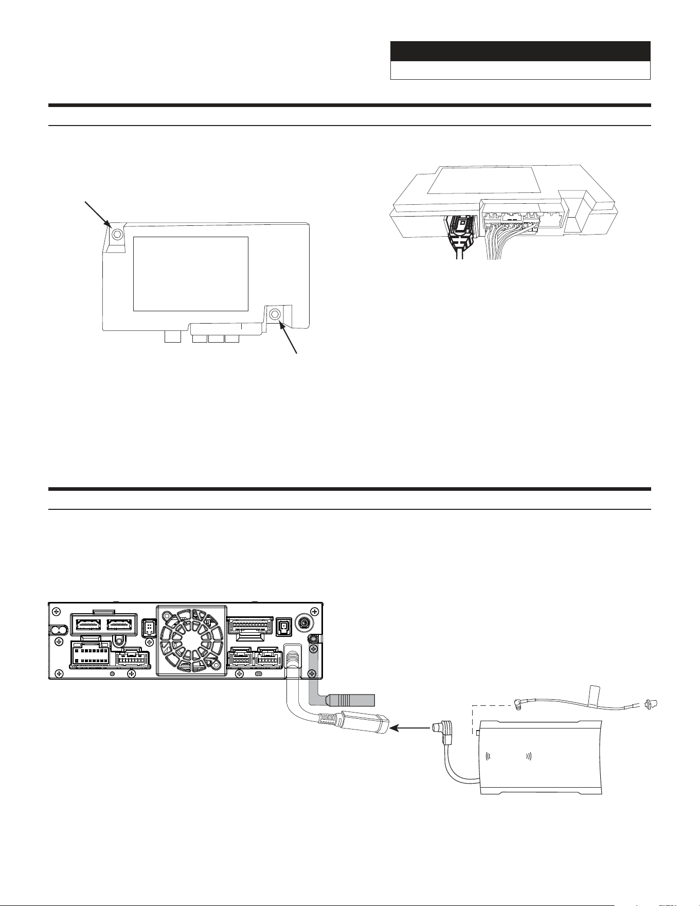
6 Route the key harness through the top-left side of
the i509 source unit. Mount the i509 source unit
using (4) 7mm factory screws.
DISCONNECT THE BATTERY BEFORE
CONTINUING. FAILURE TO DO SO WILL
DISABLE MANY FEATURES.
1 Attach the modified panel using the factory screws.
3 Apply Insulating pad by removing the paper
backing. See diagram below.
5 Route the USB extension cables to the glove box
or center console area. The black USB is for data
and the gray USB is for charging only. The black
USB is used for CarPlay and Android Auto. Connect
the main harness and other adapters to the factory
harness and secure them.
Jeep Wrangler
i509-WRA-JK 20220404v1
10/22
Removing the Uconnect® (only for vehicles with factory Uconnect®)
1 Remove the factory climate control panel. It is
clipped on and can be removed with a panel
removing tool. Extract the (2) 7mm bolts from
Uconnect® module.
3 Secure the Uconnect® module to the original
location using the 7mm bolts.
2 Disconnect the 24pin OEM connector.
4. NOTE: If Uconnect® module is not disconnected
the Uconnect® system will stay paired with
previously paired phones. The user’s phone may
connect to both Bluetooth devices simultaneously
resulting in unpredictable and potentially distracting
behavior. The feature is not retained by the i509 and
the OEM USB should not be used.
There is no way to integrate the factory SiriusXM tuner. Once the radio is removed, the factory SiriusXM is
removed. As the title states, SiriusXM requires a tuner sold separately. This diagram shows how to integrate the
antenna connection. For vehicles with factory SiriusXM connect the adapter to the factory SiriusXM antenna in the
radio cavity. The factory SiriusXM antenna is located on the passenger side B-pillar. For vehicles without factory
SiriusXM use the antenna that is included with the SXV300 SiriusXM Tuner.
Connecting A SiriusXM Module (Sold Separately)
SiriusXm
connect
PREOUT
USB
CAMERA
ANTENNA
MAIN
REMOTE
SXM
DISPLAY
EX KEY
GPS
OUT
IN
Jeep Wrangler
i509-WRA-JK 20220404v1
11/22
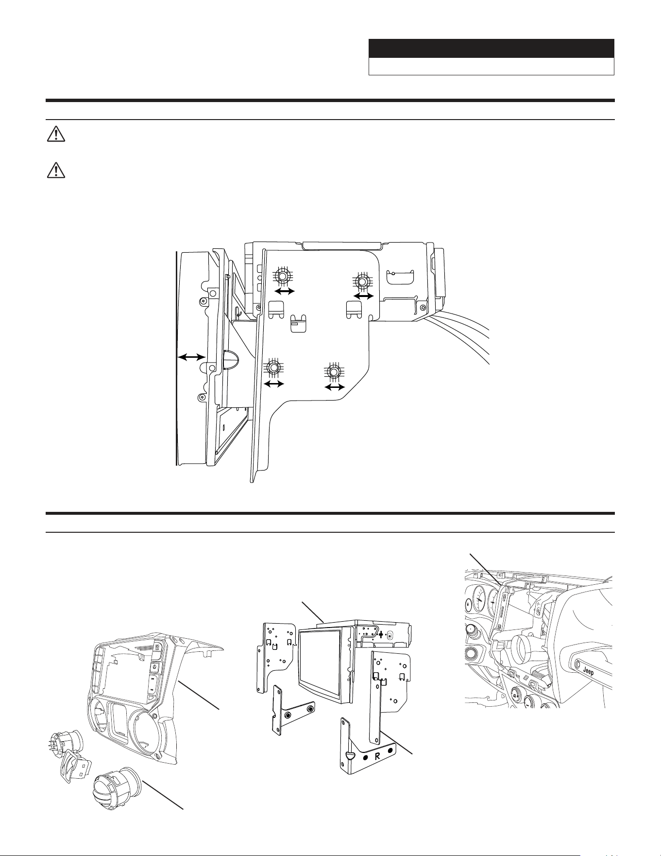
Mounting Brackets
DISCONNECT THE BATTERY BEFORE CONTINUING. FAILURE TO DO SO WILL DISABLE MANY
FEATURES.
IMPORTANT: During the research and development of this product it was discovered that mounting
tolerance may vary from the vehicle’s trim level to year built. We have added a 1mm tolerance to the
mounting brackets to compensate for such variance in mounting tolerance. Use the guides below as
reference if there are any required adjustments.
Adjust the rear bracket as needed when the top or bottom is protruding or not flushed.
Adjust the side brackets as needed when either side is protruding or not flushed.
Exploded-View Diagram
Dash Board
A
/C
i509-WRA
Radio Dash
Bezel
Factory Vents and Window
Switch Pod (not included)
i509 Source Unit
Side Mounting
Brackets
MENU
Jeep Wrangler
i509-WRA-JK 20220404v1
12/22
Bezel Wiring Diagram
8 Pin Harness
20 Pin Harness
(Connect to i509)
8 Pin Harness
Jeep Wrangler
i509-WRA-JK 20220404v1
13/22
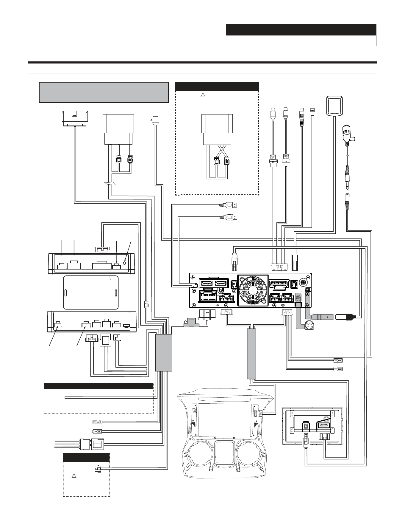
i509-WRA-JK Wiring Diagram
PREOUT
USB
CAMERA
ANTENNA
MAIN
REMOTE
SXM
DISPLAY
EX KEY
GPS
OUT
IN
To Vehicle Connectors
Rear Camera Input
To SXM Tuner
See Page 10
Direct Camera Adapter
i509 Source Unit
Power Harness
i509 - Display
Front
Rear
Rear
Front
For factory amplified vehicles switch the
speaker connectors, front to rear and
rear to front.
AMPLIFIED VEHICLES
Failure to follow this procedure will
result in no audio from Navigation and
Bluetooth sources.
Microphone
WARNING!
iDatalink MAESTRO Module
18-pin Black
Connector
10-pin Green
Connector
(Vehicle signals)
3-pin Black
Connector
(Power)
4-pin Black
Connector
(Data)
Blue Power Antenna
Blue/White Amp Turn-on
AUX Power
3-pin Black Connector
Black - Ground
Yellow -12V+
Red - Acc 12V+
To OBDII Connector
Power/Speaker
16-pin Green Connector
Front
Rear
Rear
Front
Rear View Camera
6-pin Black Connector
White/Gray Manual Transmission Reverse Input
For manual transmission vehicles ONLY. Connect the
White/Gray wire to the White/Gray wire located
on the passenger side kick panel.
Rear View Camera
WARNING!
The use of this connection
is intended for Alpine
HCE-TCAM1-WRA rear
view camera ONLY.
MANUAL TRANSMISSION VEHICLES
18-PinChime10-Pin
Red
Not
Used
Reset
Button
3-Pin 4-Pin 3-Pin 4-Pin10-Pin
Blue
Not
Used
Not
Used
If using
HCE-TCAM1-WRA
see page 17
Main Harness
Rear
Not
Used
Not
Used
Front Camera Input
Direct Camera Adapter
GPS
Antenna
Antenna
Connection
AUX Remote Out
HDMI Remote Out
Dash Cam Video In
Dash Cam Data
Black (Data) USB
Gray (Charging Only) USB
USB’s get ran to where you want to plug in
at in the vehicle. OEM and flush mount adapters
may cause issues. Plug directly into the extension.
To Dash Cam
See Page 10
To Optional
Cameras
Display Power/Key Harness
Jeep Wrangler
i509-WRA-JK 20220404v1
14/22
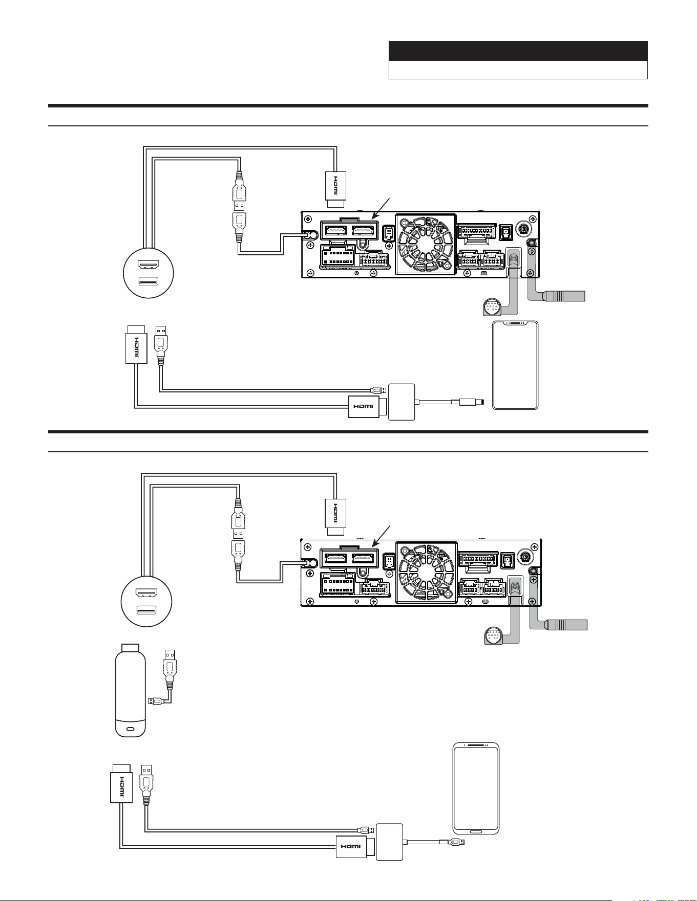
i509-WRA-JK HDMI Usage With An iPhone
Lightning To HDMI
adapter needs to be
purchased from Apple.
Third party adapters may
not work
iPhone
USB
i509-WRA-JK Source Unit
To HDMI In
The black USB is the
only one you can plug
the HDMI adapter into.
That is 2.4A and the
only USB that will power
on the HDMI adapter.
The gray USB will NOT
power on the device. This
also means that you can not
use CarPlay/Android Auto and
HDMI at the same time.
PREOUT
USB
CAMERA
ANTENNA
MAIN
REMOTE
SXM
DISPLAY
EX KEY
GPS
OUT
IN
Most HDMI devices use
copyright protections
which means it can’t be
output from the Source
Unit (a phone would be
an example of this).
i509-WRA-JK HDMI Usage With An Android Phone
For Android users some Android
phones do not have HDMI adapters.
If the phone can cast video
then you can use a Miracast adapter
(for example a Roku Stick
or Amazon Firestick).
Or
Android Phone
Some Android phones may
have a HDMI adapter. That
would be sold separately by
the phone manufacturer. Third
party adapters will not work.
USB
i509-WRA-JK Source Unit
To HDMI In
The black USB is the
only one you can plug
the HDMI adapter into.
That is 2.4A and the
only USB that will power
on the HDMI adapter.
The gray USB will NOT
power on the device. This
also means that you can not
use CarPlay/Android Auto and
HDMI at the same time.
PREOUT
USB
CAMERA
ANTENNA
MAIN
REMOTE
SXM
DISPLAY
EX KEY
GPS
OUT
IN
Most HDMI devices use
copyright protections
which means it can’t be
output from the Source
Unit (a phone would be
an example of this).
Jeep Wrangler
i509-WRA-JK 20220404v1
15/22
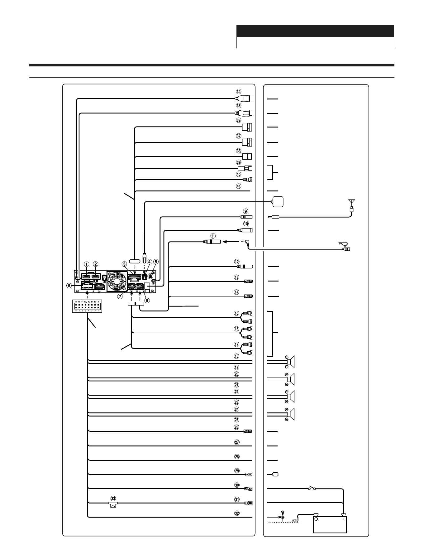
i509-WRA-JK Wiring Diagram
Antenna
Microphone (included)
To amplifier or equalizer
To plus side of the back lamp signal
lead of the car
To the parking brake signal lead
Ignition key
Battery
Power cable
PRE OUT cable
Speakers
Rear Left
Front Left
Front Right
Rear Right
To input terminal of amplifier
when adding an external
amplifier
REAR OUT
REMO
(Blue/White)
REVERSE
(Violet/White)
PARKING BRAKE
(Yellow/Blue)
ACC
(Red)
BATT
(Yellow)
GND
(Black)
(Green)
(Green/Black)
(White)
(White/Black)
(Gray/Black)
(Gray)
(Violet/Black)
(Violet)
SUBW
FRONT OUT
P. ANT
(Blue)
To power antenna
STEERING REMOTE
HDMI-REMO-OUT
AUX-REMO-OUT
To steering remote control
interface
To HDMI Selector Interface
To AUX device (TV Tuner, etc.)
REMOTE cable
(Brown)
(Gray)
MIC IN
To SiriusXM Tuner
To USB flash drive, iPhone or
Android smartphone.
To iPhone or Android smartphone
(For charging only).
To Rear camera
To Front or Side camera
To iDataLink module
To Dash Cam
GPS Antenna (Included)
USB cable 2.4A (Black)
USB cable 1.5A (Gray)
REAR CAMERA
FRONT CAMERA
IDATALINK I/F
LIN
DRIVE RECORDER IN
CAMERA cable
To the vehicle speed pulse line
SPEED SENSOR
(Green/White)
Jeep Wrangler
i509-WRA-JK 20220404v1
16/22
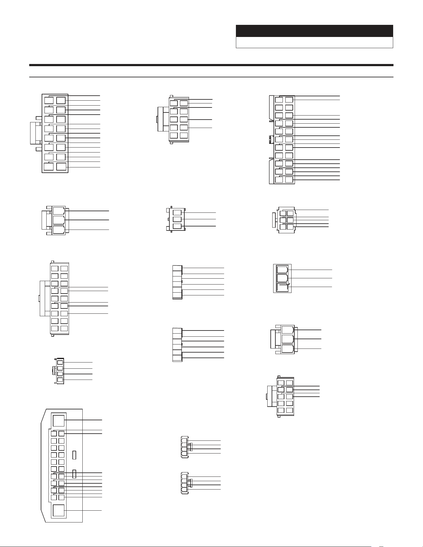
Wire Harness Pin Outs
Cam Aux Data
Red 22AWG
Purple 22AWG
Black 22AWG
Black 22AWG
Blue 22AWG
Red/White 22AWG
White 22AWG
Purple 22AWG
White 22AWG
White 22AWG
Black 22AWG
Black 22AWG
1
2
3
4
5
6
7
8
9
10
11
12
13
14
15
16
Radio Main
Blue 22AWG
Red 20AWG
Blue/White 22AWG
Orange/White 22AWG
Yellow/Blue 22AWG
Purple 20AWG
Gray 20AWG
Purple/Black 20AWG
Gray/Black 20AWG
Green 20AWG
White 20AWG
Green/Black 20AWG
White/Black 20AWG
Yellow 18AWG
Black 18AWG
1
2
3
4
5
6
Front Camera
Black 22AWG
Black 22AWG
Red 22AWG
Blue 22AWG
Black 22AWG
White 22AWG
3
5
1
4
6
2
Rear Camera
Black 22AWG
Yellow/Black 22AWG
Red 22AWG
Orange/White 22AWG
Orange 22AWG
1
2
3
Key Harness
Black/Silver 22AWG
Orange/Silver 22AWG
Pink/Silver 22AWG
1
2
3
Power/ACC
Yellow 18AWG
Red 18AWG
Black 18AWG
1
2
3
Yellow 18AWG
Red 18AWG
Black 18AWG
AUX Power Pigtail
Data SWC
12
11
13
14
16
15
17
18
1
2
4
3
6
5
8
7
9
10
Brown/Red 22AWG
Brown/Yellow 22AWG
Red/Brown 22AWG
Yellow/Brown 22AWG
Yellow/Black 22AWG
1 2
43
6
5
87
9 10
Audio In
White/Red 22AWG
White/Brown 22AWG
Grey/Red 22AWG
White/Brown 22AWG
4
6
87
9 10
1 2
3
5
Radio I/O
Orange 22AWG
White/Grey 22AWG
Orange/White 22AWG
Yellow/Blue 22AWG
Blue/White 22AWG
1
2
3
Yellow 18AWG
Red 18AWG
Black 18AWG
AUX Power
4
1
2
3
iDatalink
Blue 22AWG
White 22AWG
Black 22AWG
Red 22AWG
1
2
3
4
5
6
7
8
9
10
11
12
13
14
15
16
17
18
19
20
21
22
Brown/Yellow 22AWG
Gray 20AWG
Brown/Red 22AWG
Yellow 18AWG
Black 18AWG
Green 20AWG
Gray/Black 20AWG
Green/Black 20AWG
White 20AWG
Purple 20AWG
White/Black 20AWG
Purple/Black 20AWG
1
2
3
4
Wrangler Harness
Purple 20AWG
Purple/Black 20AWG
Green 20AWG
Green/Black 20AWG
Speaker Harness
1
2
3
4
Gray 20AWG
Gray/Black 20AWG
White 20AWG
White/Black 20AWG
Speaker Harness
1
2
3
4
5
6
Rear Camera
Black 22AWG
Black 22AWG
Red 22AWG
Blue 22AWG
Black 22AWG
White 22AWG
1 2
3
9
11
13
15
17
4
8
10
12
14
16
18
5
7
6
19
20
21
22
Blue/White 22AWG
Black/White 22AWG
Black/White 22AWG
Blue/White 22AWG
Jeep Wrangler
i509-WRA-JK 20220404v1
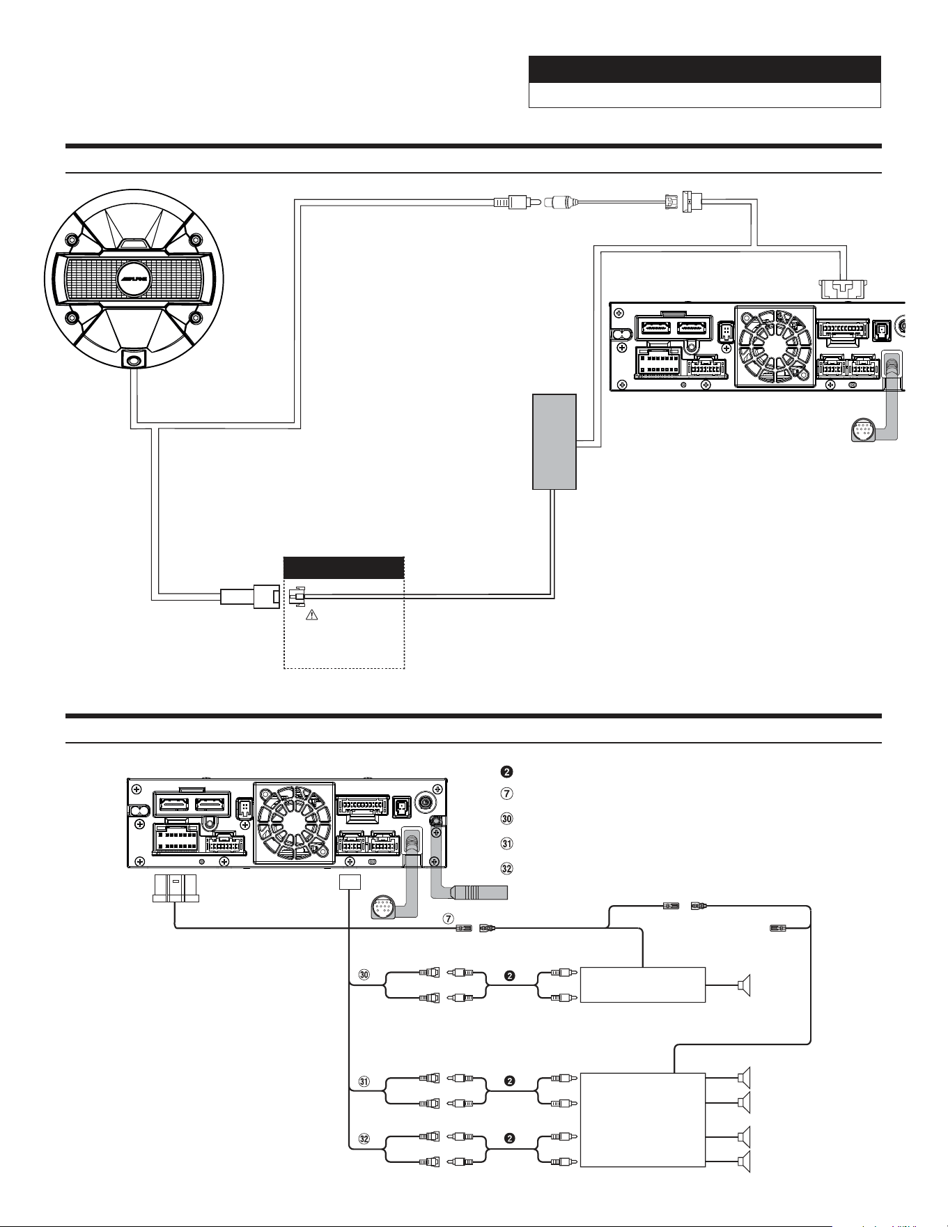
17/22
Remote Turn-On Lead (Blue/White)
Subwoofer RCA Connectors
Front Output RCA Connectors
Rear Output RCA Connectors
RCA Extension Cable (sold separately)
(Blue/White)
REMOTE ON
(Blue/White)
Subwoofer
REMOTE
Amplifier for subwoofer
(sold separately)
To subwoofer input terminal
(Red)
(White)
SUBW
FRONT OUT
REAR OUT
To front input terminal
Amplifier 4 ch
(sold separately)
To rear input terminal
Front speaker
Rear speaker
REMOTE ON
(Blue/White)
(Red)
(White)
(Red)
(White)
PREOUT
USB
CAMERA
ANTENNA
MAIN
REMOTE
SXM
DISPLAY
EX KEY
GPS
OUT
IN
Connection Of An External Amplifier
Connection Of HCE-TCAM1-WRA (Sold Separately)
i509-WRA-JK Source Unit
To HCE-TCAM1-WRA
Direct Camera Input
Direct Camera Adapter
i509 JK Source Unit
Rear View Camera
6-pin Black Connector
Main Harness
Rear View Camera
WARNING!
The use of this connection
is intended for Alpine
HCE-TCAM1-WRA rear
view camera ONLY.
To HCE-TCAM1-WRA
This connection goes to
the direct video input of
the head unit through the
adapter. If you do not make
this connection there will be
no video to your i509-WRA-JK
This connection goes to
the camera connector on
the main harness. This
handles the power, ground,
reverse light, and illumination
connections.
PREOUT
USB
CAMERA
MAIN
REMOTE
SXM
DISPLAY
EX KEY
GPS
OUT
IN
Jeep Wrangler
i509-WRA-JK 20220404v1
18/22
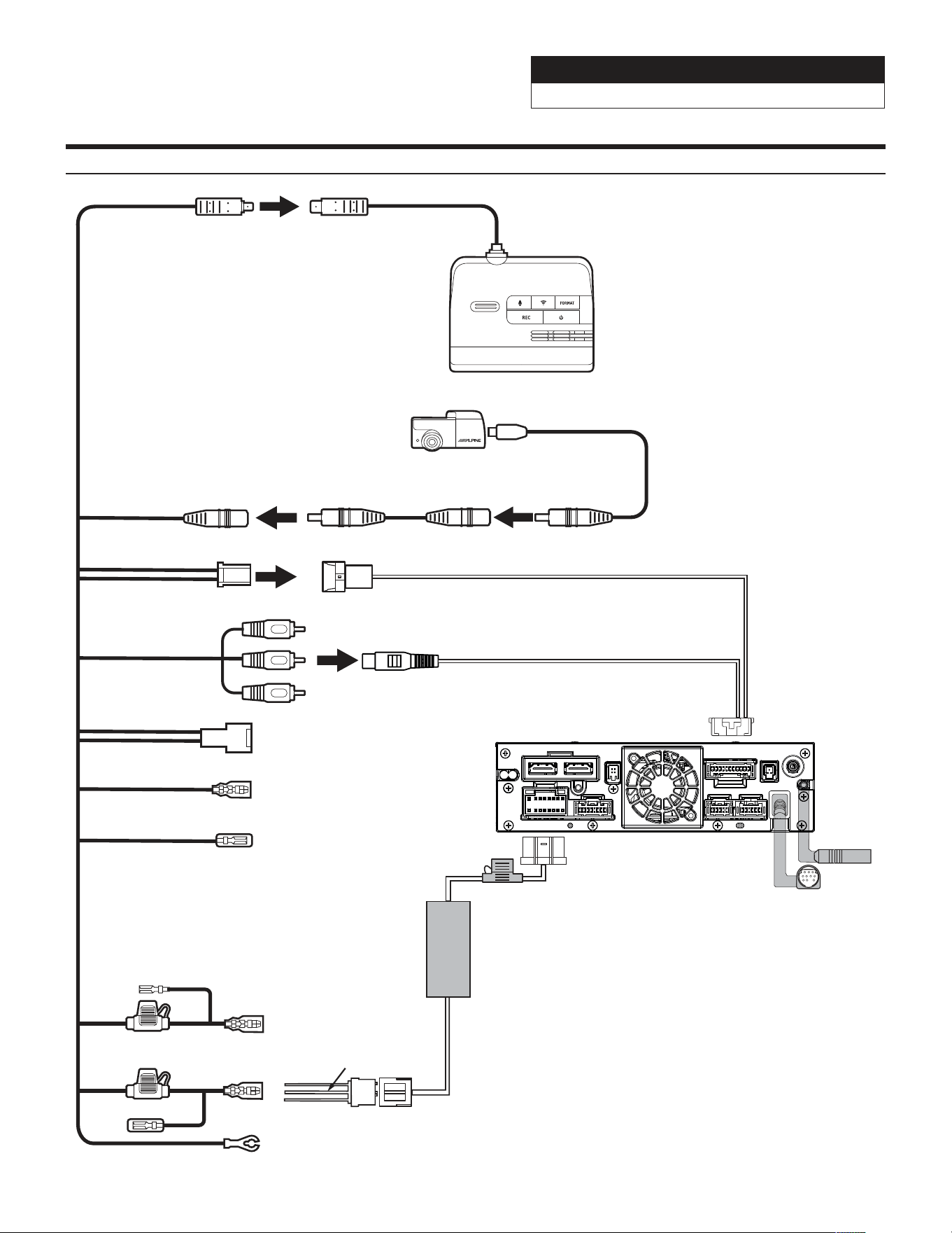
Connection Of DVR-C320R/C310R (Sold Separately)
PREOUT
USB
CAMERA
ANTENNA
MAIN
REMOTE
SXM
DISPLAY
EX KEY
GPS
OUT
IN
i509 Source Unit
Power Harness
AUX Power
3-pin Black Connector
Black - Ground
Yellow -12V+
Red - Acc 12V+
Main Harness
Yellow
Red
Black
Cut the terminals.
Solder and heat shrink
to AUX Power Connector.
Remocon Out
Remocon In
Lin Cable
Lin Cable
F Cam
R Cam
Hardwiring Cable
DVR-C320R/C310R
Dash Cam Video In
Dash Cam Data
Not Used
Rear Camera Cable
Rear Camera
Extension Cable
Rear Camera
Not Used
Not Used
Jeep Wrangler
i509-WRA-JK 20220404v1
19/22
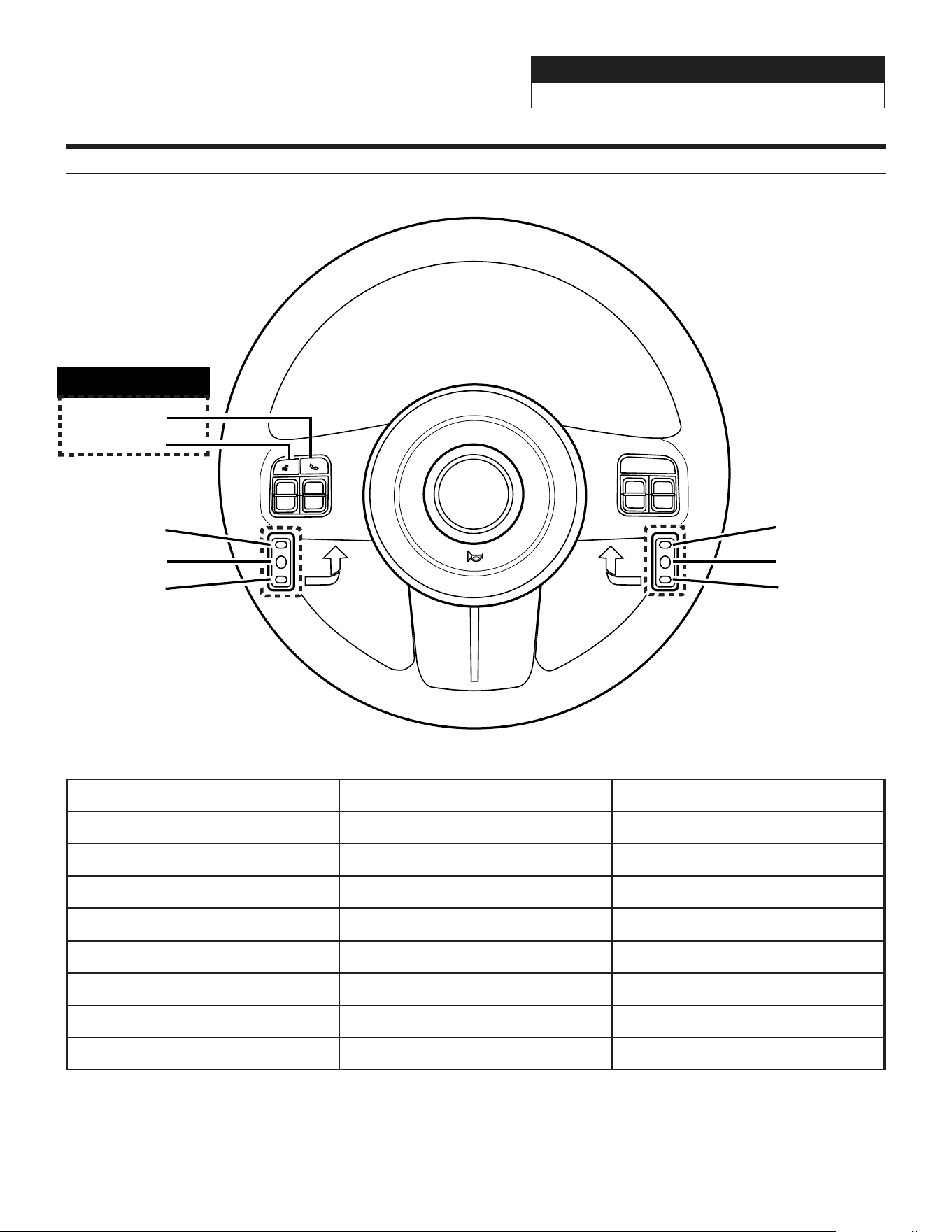
Steering Wheel Configuration
Button Press Once Press And Hold
Volume Up Volume + None
Volume Down Volume - None
Seek Up Track + None
Seek Down Track - None
Source Source Band
Next Preset Preset & Folder + Preset & Folder -
Voice Voice Or Siri None
Phone Answer Call Hang Up & Reject Call
VR
Seek Up
Preset Up
Seek Down
Volume Up
Volume Down
Source
Phone
Voice
Factory Option
Jeep Wrangler
i509-WRA-JK 20220404v1
20/22
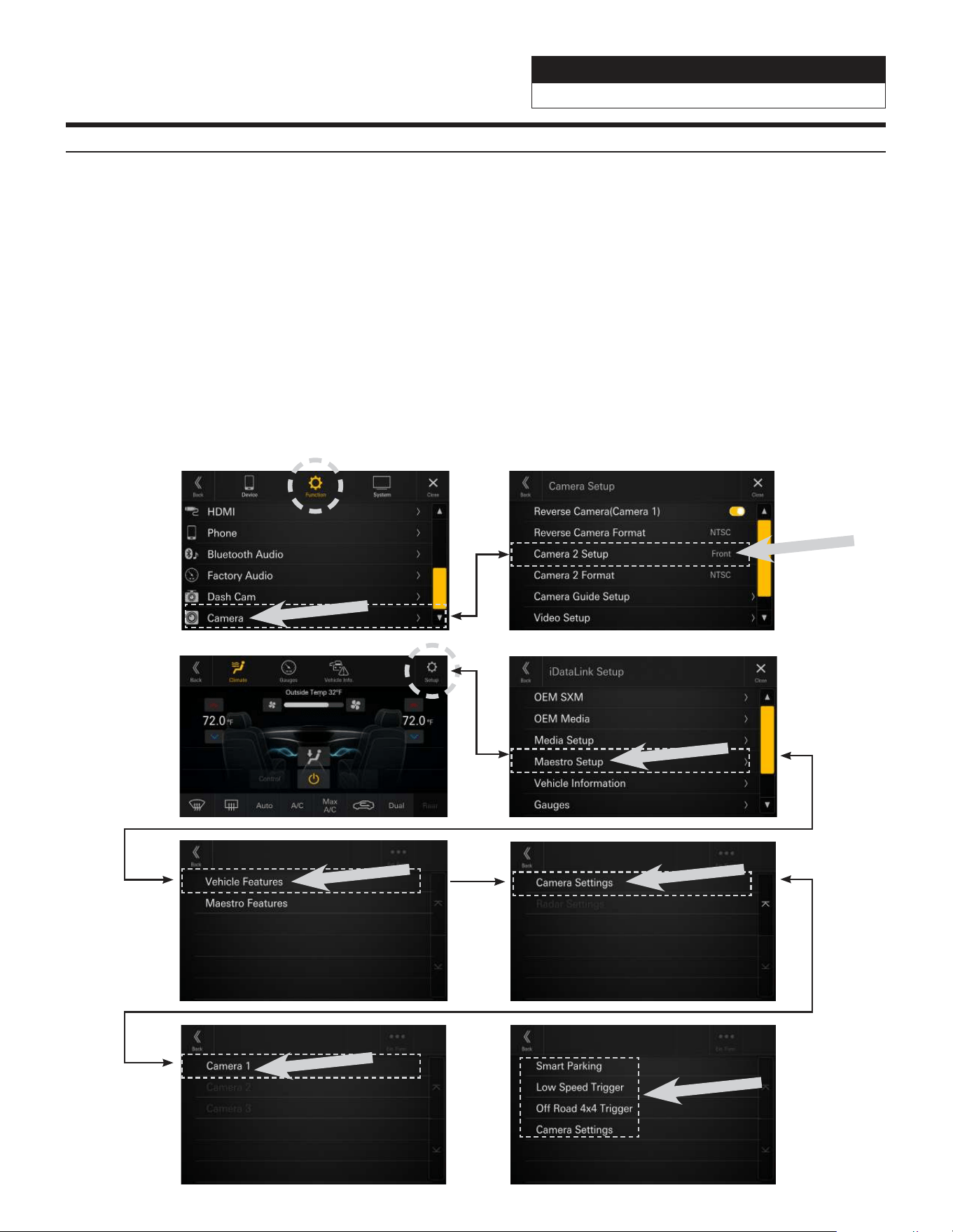
Setting Up Advanced Camera Features
1 Once in the setup menu (see page 21) select FUNCTION and then CAMERA.
2 Select CAMERA 2 SETUP. The camera 2 input needs to be set to FRONT or SIDE. This will let the Maestro
module know the second camera is active and that will enable the CAMERA SETTINGS in the Maestro Setup
Menu.
3 In the Maestro screen select SETUP.
4 Select MAESTRO SETUP. (Note this path in the settings can vary slightly with different Maestro firmwares).
5 Select VEHICLE FEATURES.
6 Select CAMERA SETTINGS.
7 Select Camera Assignment then CAMERA 1. The available options are FRONT CAMERA, RIGHT LANE WATCH
CAMERA, and LEFT LANE WATCH CAMERA.
8 Once CAMERA 1 is set the corresponding camera settings will then be available.
1 2
3 4
5 6
7 8

Jeep Wrangler
i509-WRA-JK 20220404v1
21/22
Set Up Guide
1 Turn the vehicle’s Ignition switch to ACC.
2 Turn ON the i509-WRA-JK by pressing any key.
4 To get into the settings the parking brake sequence needs to be done. Engage the parking brake, release
the parking brake, and engage the parking brake again.
5 Vehicle information- Set the desired gauge information. (HOME/VEHICLE INFO/SETUP).
6 If a rear camera is present, turn it ON in the system menu. (HOME/FUNCTION/CAMERA/REVERSE CAMERA).
Troubleshooting Guide
Symptom Possible Cause Remedy
1
iPhone not working with
HDMI.
Not using Apple HDMI to Lightning
adapter.
Purchase the HDMI to Lightning adapter
directly from Apple. Not all 3rd party
adapters work the same.
Didn’t plug USB power into a 2A
source.
Do not plug into the USB from the Alpine
head unit. A third party USB adapter will
need to be used that is 2A.
2
Android phone is not working
with HDMI.
Using incorrect HDMI adapter.
If the phone has the feature to use an HDMI
adapter it must be the one purchased from
the manufacturer of the phone, not a third
party adapter.
Miracast adapter isn’t plugged into
a 2A source.
Do not plug into the USB from the Alpine
head unit. A third party USB adapter will
need to be used that is 2A.
Miracast adapter has resolution
settings that are too high.
Plug the adapter into another monitor (for
example a television in the home) and reduce
the resolution settings.
3
iDatalink website says serial
number is invalid.
Incorrect serial number is being
used.
In the i509-WRA-JK settings confirm the
serial number. MENU/SETUP/GENERAL/
ABOUT.
Serial number may not be in
iDatalink database.
Call ADS at 1-866-427-2999 and verify.
4 No output from RCA’s
Maestro module is flashed for
amplified system.
Re-flash module for non-amplified system.

Jeep Wrangler
i509-WRA-JK 20220404v1
22/22
Troubleshooting Guide Continued
Symptom Possible Cause Remedy
5
Headunit will not turn on.
Incorrect serial number was used
when flashing maestro.
Flash Maestro with correct serial number.
4 pin Maestro data cable is
disconnected or damaged.
Check for proper connection or
disconnected pins.
OBD2 cable is not plugged in. Connect OBD2 connector to the OBD2 port.
Monitor or main harness are not
connected.
Check for proper connection or
disconnected pins.
6
Cannot enter SETTINGS
MENU.
Vehicle is in motion or parking
brake is not engaged.
With vehicle in (P)PARK engage the parking
brake. Release the parking brake and
engage the parking brake a second time, as
shown in the Setup Guide on page 21.
8
Only the front speakers are on
for SXM Radio.
SXM Tuner has not been activated. Activate SXM Tuner.
9
The vehicle is incorrectly
positioned on the Navigation
display.
Poor GPS signal.
Ensure the recommeded GPS antenna route
was used. See page 6.
10
CarPlay, Android Auto, or
off-road navigation map
positioning issues.
GPS antenna is positioned
incorrectly.
GPS antenna is obstructed and doesn’t have
line of sight to the sky. Perform a factory
reset. The unit will automatically recalibrate.
11
CarPlay, Android Auto, or
off-road navigation vehicle
position icon heading in
wrong direction
Reverse Signal is not connected or
not reliable.
Ensure that Reverse wire is connected. Also
ensure that no 3rd party interface module(s)
interfere with the Reverse Signal. The head
unit uses the Reverse Signal to achieve
optimal positioning performance.
12
iPhone or Android phone is
not recognized
when connected to the
USB cable.
Loose or disconnected USB cable.
Check the USB connection behind
the headunit.
Non-compatible cable.
Use the cable supplied with the
iPhone or Android phone. Third party
adapters and long extensions may not work.
Only use USB extension that came with the
head unit.
Dirty charging port on phone. Clean charging port.
13
Rear camera doesn’t activate
when vehicle is in reverse.
The rear camera wasn’t turned on
in the settings
Follow the setup guide on the previous page.
14
Rear camera just shows
cones in reverse.
The rear camera that was used
either is not powered on properly
or there is an issue with the video
connection.
Test the power wires of the rear camera with
a digital multimeter to ensure they have the
proper voltage. Test the video output of the
camera with a test monitor to make sure it is
outputting a picture.
