Jeep Wrangler
i509-WRA-JL 20220401v1
1/29
Jeep Wrangler
i509-WRA-JL
9” Restyle In-Dash System
Installation Manual
Model: Wrangler JL 2018-Up
Model: Gladiator JT 2020-Up
Note
Design and specifications are subject to change without notice for improvement.
To Ensure Safe Use, Always Follow These Precautions
The installation of this product requires specialized skills and experience. This is an installation that is
challenging and time consuming even for installers with experience. A professional installer would typically
take a minimum of 3-4 hours to complete this installation. We recommend that you have the product installed
by an Alpine authorized dealer.
Before you use this product, be sure to carefully read this installation manual and the separate user's manual
so that you can use the product correctly. Alpine Electronics bears no responsibility for problems that arise as
a result of failure to follow the instructions in the manuals.
This manual includes a number of symbols that are intended to help you use the product safely, to prevent
harm to you and others, and to protect against damage to property. These symbols and their meanings are
listed below. Make sure you fully understand these symbols before you begin reading the main text.
Explanations of Injury and Damage That May Result from Incorrect Use
Warning
Ignoring the content marked by this indication and using the product incorrectly is
expected to lead to death or serious injury.
Caution
Ignoring the content marked by this indication and using the product incorrectly is only
expected to lead to injury or property damage.
Jeep
Model Year
Wrangler JL** 2018 - Up
Gladiator JT** 2020 - Up
** OEM amplified vehicles require the KCX-F200INT (sold separately)
* The specified vehicles have been tested and have met compatibility specs at the time of testing. Compatibility is
not guaranteed if the manufacturer has made production changes to the listed vehicles above.
Introduction
Congratulations on purchasing the i509-WRA-JL. This installation manual is designed to take you through
the step-by-step installation of i509-WRA-JL into a 2018-Up Jeep Wrangler JL or Jeep Gladiator JT 2020-
Up. Please familiarize yourself with the owners manual as this is a challenging installation. If you still have
additional questions please call 1-800-TECH-101.
Jeep Wrangler
i509-WRA-JL 20220401v1
2/29
Forbidden
Indicates actions that are
forbidden (must not be
performed)
Forbidden
Indicates that disassembly is
forbidden.
Mandatory
Indicates actions that are
mandatory (must be performed)
Marks content that should receive
your full attention.
Warning
Do not disassemble or modify the product.
Doing so could lead to an accident, fire, or
electric shock.
Forbidden
Store screws and other small objects where
children cannot reach them. If one of those
small objects is swallowed, consult with a
doctor immediately.
When replacing fuses be sure to
use the fuses with the specified current
rating. Failing to do so could lead to
an accident or fire.
Forbidden
Only connect the product to a 12 VDC negative
ground car. Failing to do so could lead to an
accident or fire.
Mandatory
Since this vehicle has two batteries, discon-
necting the battery is not a good option. Take
caution when testing circuits. Failing to do so
could lead to electric shock or injury.
Do not cut the insulation on a cord and take
power from another device. Doing so could
lead to fire or electric shock.
Forbidden
Do not install the product in a location where
it willl obstruct the driver’s forward view;
interfere with the operation of the steering
wheel, gear shift, or the like; or pose a threat
to passengers. Doing so could lead to an ac-
cident or injury.
Forbidden
When making a hole in the vehicle body, be
careful to avoid damaging pipes, the fuel tank,
electrical wiring, and the like. This kind of
damage could lead to an accident or fire.
When installing and grounding the product, do
not use any of the bolts or nuts of the steering
wheel, brakes, fuel tank, or the like. Doing so
could make the brakes stop working or could
lead to fire.
Forbidden
Do not install the product near the passenger-
side airbag. Doing so could interfere with the
operation of the airbag and lead to an acci-
dent or injury.
Forbidden
Bundle cords so that they don’t interfere with
driving. Wrapping cords around the steer-
ing wheel, gearshift, brake pedal, or the like
could lead to an accident or damage equip-
ment.
Caution
Connect the product properly according to the
instructions. Failing to do so could lead to fire
or an accident.
Forbidden
Do not sandwich cords between the seat
railing or allow them to touch protrusions. Re-
sulting breaks or shorts could lead to electric
shock or fire.
Do not block vents or heat sinks. Doing so
could lead to fire or damage equipment.
Use the accessories according to the instruc-
tions, and attach them securely. Failing to
do so could lead to an accident or damage
equipment.
Forbidden
Do not install the product where it may be ex-
posed to water or in a place with high levels
of humidity or dust. Doing so could lead to fire
or damage equipment.
Forbidden
The installation and wiring of this product re-
quires specialized skills and experience. Have
the product installed by an Alpine authorized
dealer.
Types of Precautions
Mandatory
Jeep Wrangler
i509-WRA-JL 20220401v1
3/29
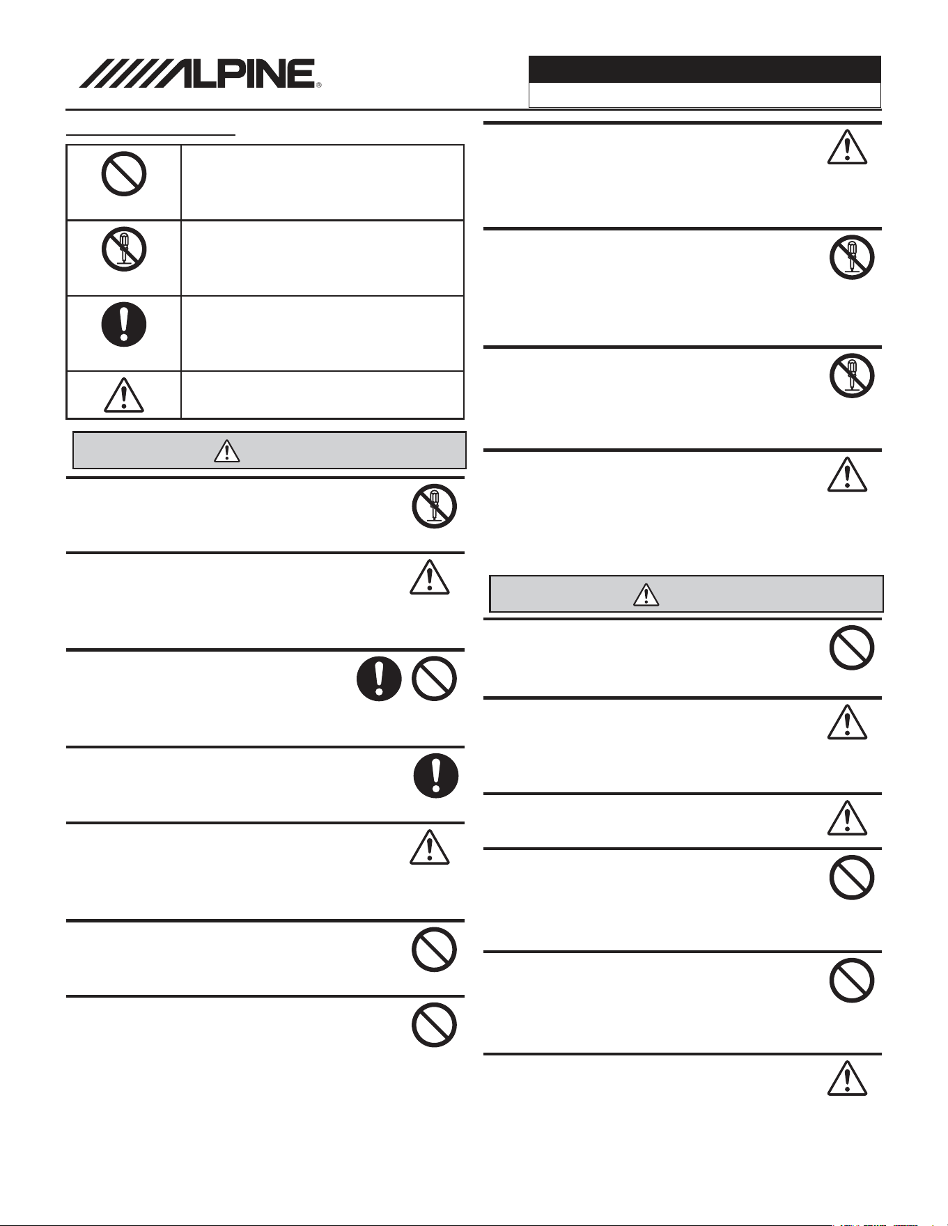
Tools Required
10mm Socket 8mm Socket 7mm Socket
Wire Cutters Extension Ratchet
#2 Phillips Screwdriver Torx T20 Torx T47
Panel Removal Tools Wire Fishing Tool Cordless Power Drill
Digital Multimeter
Jeep Wrangler
i509-WRA-JL 20220401v1
4/29
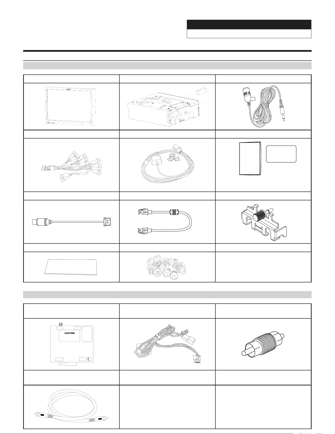
Accessory List
Head Unit Box Parts (i509)
i509 Display Unit i509 Source Unit External Bluetooth Mic
AUX/Pre Out Harness GPS Antenna Documents
Alpine
Registration Card
Quick
Reference
Guide
Direct Camera Adapter Display Cable Source Unit HDMI Bracket
Anti-Vibration Foam
Screws M5X8LMM x 12
Rear Camera Retention (SGS-BSV1-WJL V2.0)
Camera Module Camera Power Harness Camera Male To Male RCA
Coupler
SGS-BSV1-WJL
FACTORY CAMERA BSV INTERFACE
LVDS INUSB Flash
DIP1:
UP=Wrangler
Down=Gladiator
DIP 2,3,4,5,6,7,8
All up
DIP7:
Down=Firmware Update
VIDEO OUT
Power & CAN
IN
Can1
Can2
Rear Camera RCA
(Not Used)
Jeep Wrangler
i509-WRA-JL 20220401v1
5/29
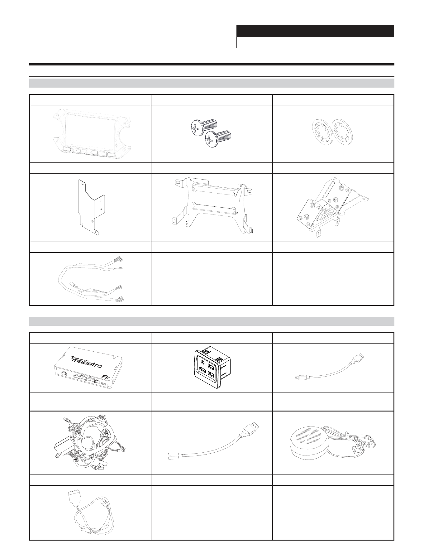
Accessory List
Installation Kit
i509-WRA-JL Display Bezel Screws M5X10LMM x 2 Lock Washers x 2
Power Inverter Bracket Display Bracket Tuner Bracket
Display Power/Key Harness
iDatalink Maestro Box Parts (ALP-MRR/ALP-HRN-WJL3)
iDatalink Maestro Module USB, HDMI, Aux Interface Maestro Flashing Cable
Main Harness
Mini USB To USB For Center
Console Power
Chime Speaker
USB Power Adapter
Jeep Wrangler
i509-WRA-JL 20220401v1
6/29
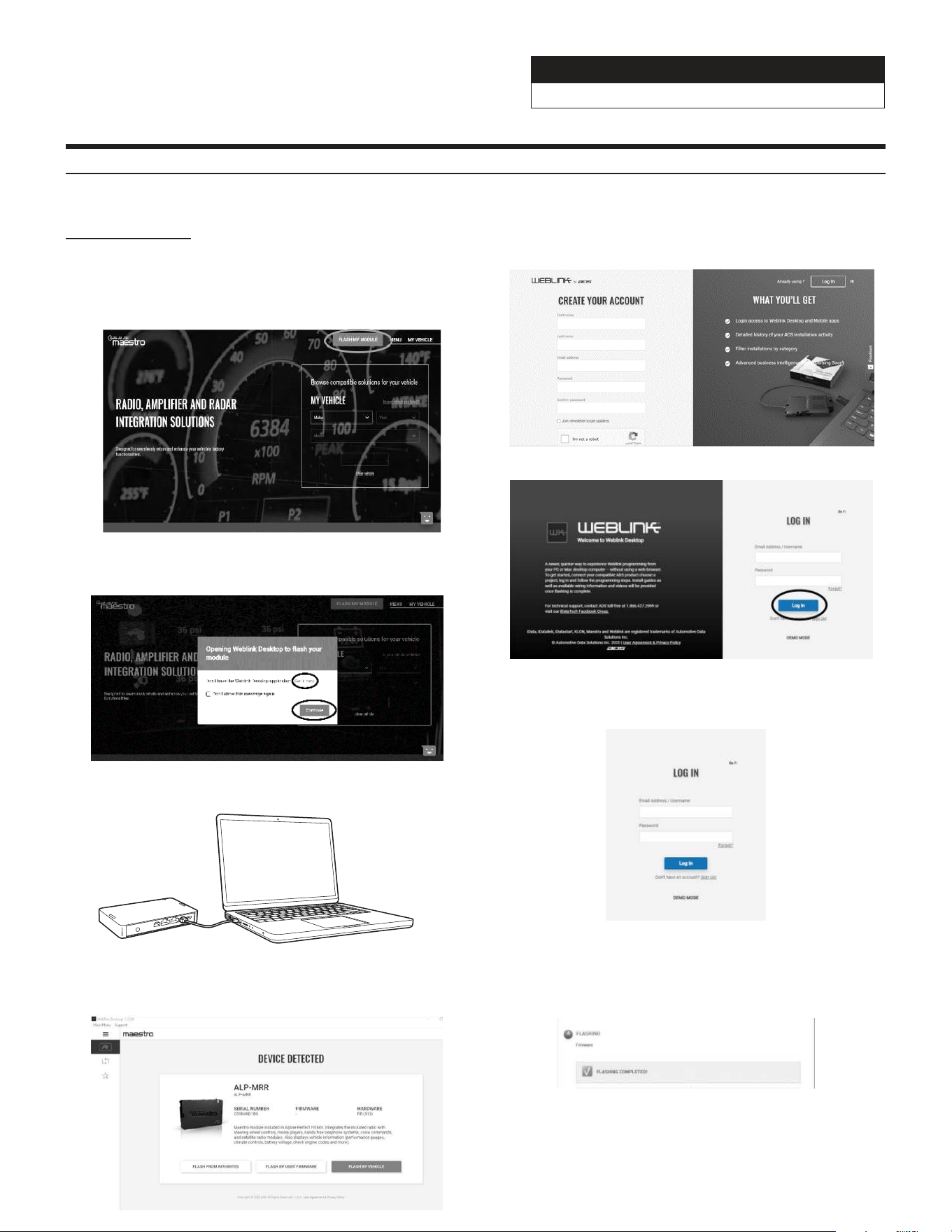
1 INSTALL THE WEBLINK PLUG-IN
Go to:
3 CONNECT YOUR MAESTRO MODULE
Use your Maestro module to connect to your PC.
5 PROGRAM YOUR MODULE
Follow the programming steps for your vehicle.
A conrmation email will be sent to you requiring validation.
For existing customers, click log in.
4 LOG INTO WEBLINK
Enter your username and password, then click OK.
6 Once Programing is complete “FLASHING
COMPLETED!” will be displayed.
Proceed to the next page to complete installation.
NOTE: If serial number is invalid, Call ADS at
1-866-427-2999 with the serial number.
Programming The iDatalink Maestro Module
idatalinkmaestro.com and follow the installation steps. The
Maestro module must be programmed specifically for each vehicle
and radio. Take care to enter the correct vehicle information,
factory options, head unit model, and head unit serial number.
The head units serial number is an alphanumeric value which is
found on the head units label, underneath the bar code.
If the plugin is already installed, Click "Continue" and follow the
prompts to open. If Plug in is not installed Click "Get it now" and
follow prompts to downlaod and install the plug-in
2 REGISTER A WEBLINK ACCOUNT
Go to:
Sign Up and complete the registration process.

Jeep Wrangler
i509-WRA-JL 20220401v1
7/29
About The Installation
2019 Jeep
Wrangler
Sport Sport S Sport
Altitude
Sahara Rubicon Sahara
Altitude
MOAB
5.0” Touchscreen
Display
Standard Standard Standard Not Available Not Available Not Available Not Available
7.0” Touchscreen
Display
Not Available Not Available Not Available Standard Standard Standard Standard
115V Power
Outlet
Not Available Not Available Not Available Standard Standard Standard Standard
Cold Weather
Group
Not Available Optional Optional Optional Optional Optional Optional
The different trim levels of the Wragler JL and the Gladiator JT come with different options which will make
the installation vary slightly. If the vehicle has the 115V Power outlet or the Cold Weather Group package
then there are different brackets that will need to be used. If your vehicle does not have those then you will
not need to use those. If you are installing the i509-WRA-JL in a Gladiator JT then a few of the steps will vary
slightly so please take notice to this as you go through the installation. Also the screen size in the pictures may
be different if you have the 5.0” display. The following chart shows which options are available on the different
trim levels for the Wrangler JL.
Retained Features
STEERING WHEEL CONTROLS
Two Functions on Each Button
■
Standard and Expanded Radio Functions
■
NAVIGATION OUTPUTS
Accessory Power Output (15A)
■
Parking Brake Output
■
Reverse Light Output
■
Vehicle Speed Pulse Output
■
Foot Brake Output
■
FACTORY AMPLIFIER
Amplifier Turn on
■
Speed Compensated Volume (Premium Audio)
■
Digital Fader (Premium Audio)
■
DSP Settings (Premium Audio)
■
Gain Adjustment (Premium Audio)
■
SECONDARY VEHICLE DISPLAY (IF EQUIPPED)
Audio Information Display
■
Hands Free Info Display
■
Navigation Info Display
■
VEHICLE SETTINGS
Access And Modify Vehicle Settings
■
CLIMATE CONTROL
Climate Display And Control On Radio
■
GAUGES
Selectable Performance Gauges
■
“Track Pack” Gauges
■
Read/Reset Check Engine Codes
■
PARK ASSIST
Retain Parking Assist Chimes
■
Distance Display On Screen
■
VEHICLE INFO
Tire Pressure Display
■
Battery Voltage Display
■
Read/Reset Check Engine Codes
■
Door open Status and Warning
■
ACCESSORIES
OEM Accessory Control Integration
■
ADVANCED CAMERA FEATURES
Front Camera Auto Control
A) Smart Parking
B) Low Speed Trigger
■
Side Camera Auto Control
A) Right Lane Watch
B) Left Lane Watch
■
4X4 Front Camera Control
A) Offroad 4X4 Trigger
■
Jeep Wrangler
i509-WRA-JL 20220401v1
8/29
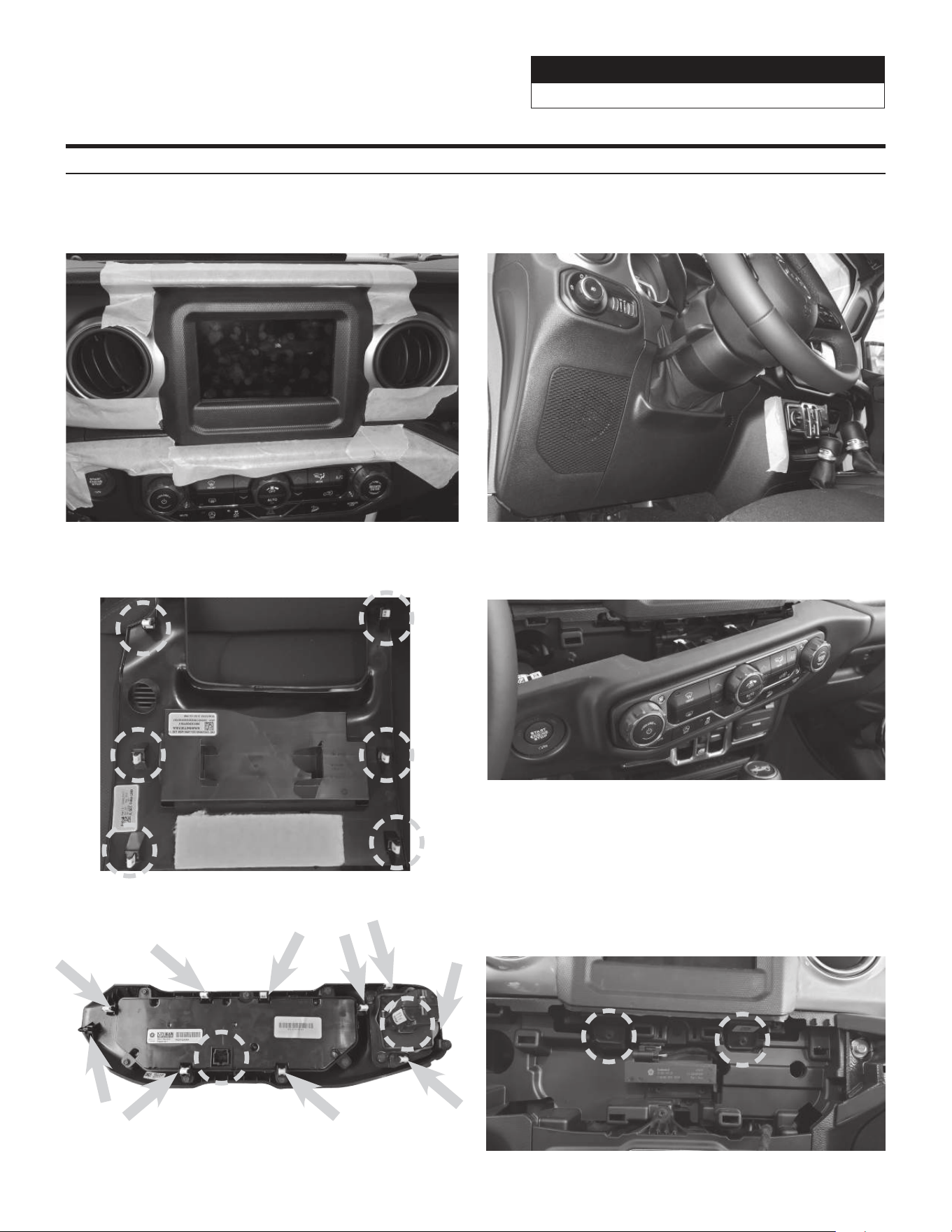
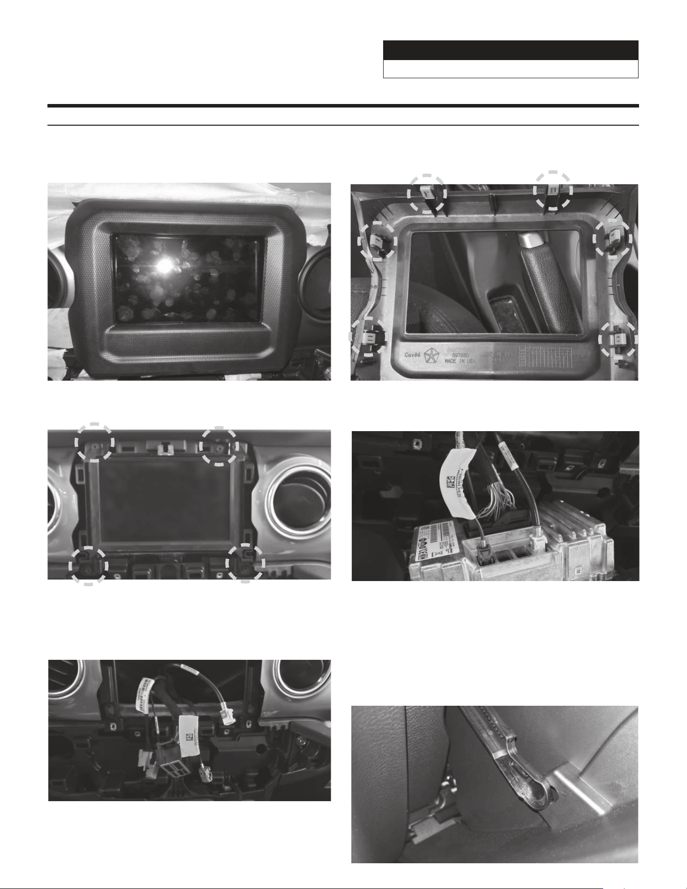
Factory Unit Disassembly Process
1 As a precautionary measure it’s a good idea to
mask out the dashboard and panels to prevent
scratches.
2 Unsnap the 6 clips and remove the knee panel
under the steering wheel using a panel removal
tool.
3 The locations of the 6 clips from the previous step. 4 Unsnap 10 clips, unplug the 2 harnesses, and
remove HVAC panel using a panel removal tool.
5 Locations of the clips and harnesses of the HVAC
controls from the previous step.
6 Use #2 Phillips Screwdriver to extract (2) screws
from the bottom of the radio bezel.
Jeep Wrangler
i509-WRA-JL 20220401v1
9/29
Factory Unit Disassembly Process (Continued)
7 Unsnap 6 clips and remove radio bezel using a
panel removal tool.
8 Unsnap the 6 clips and remove the knee panel
under the steering wheel using a panel removal
tool.
9 Use #2 Phillips Screwdriver to extract (4) screws
from head unit. Disconnect and remove the radio.
10 Disconnect the harnesses behind the OEM head
unit.
11 The disconnected harnesses from the previous
step. These will be used later to connect to the
main harness in the installation.
12 Open the glove compartment and remove
all contents, push up the glove compartment
travel stop and lower the door, pivot the glove
compartment downward, release latch on left side
of the glove compartment by pushing it upward,
pull the glove compartment upward to remove it
from the pivot.
Jeep Wrangler
i509-WRA-JL 20220401v1
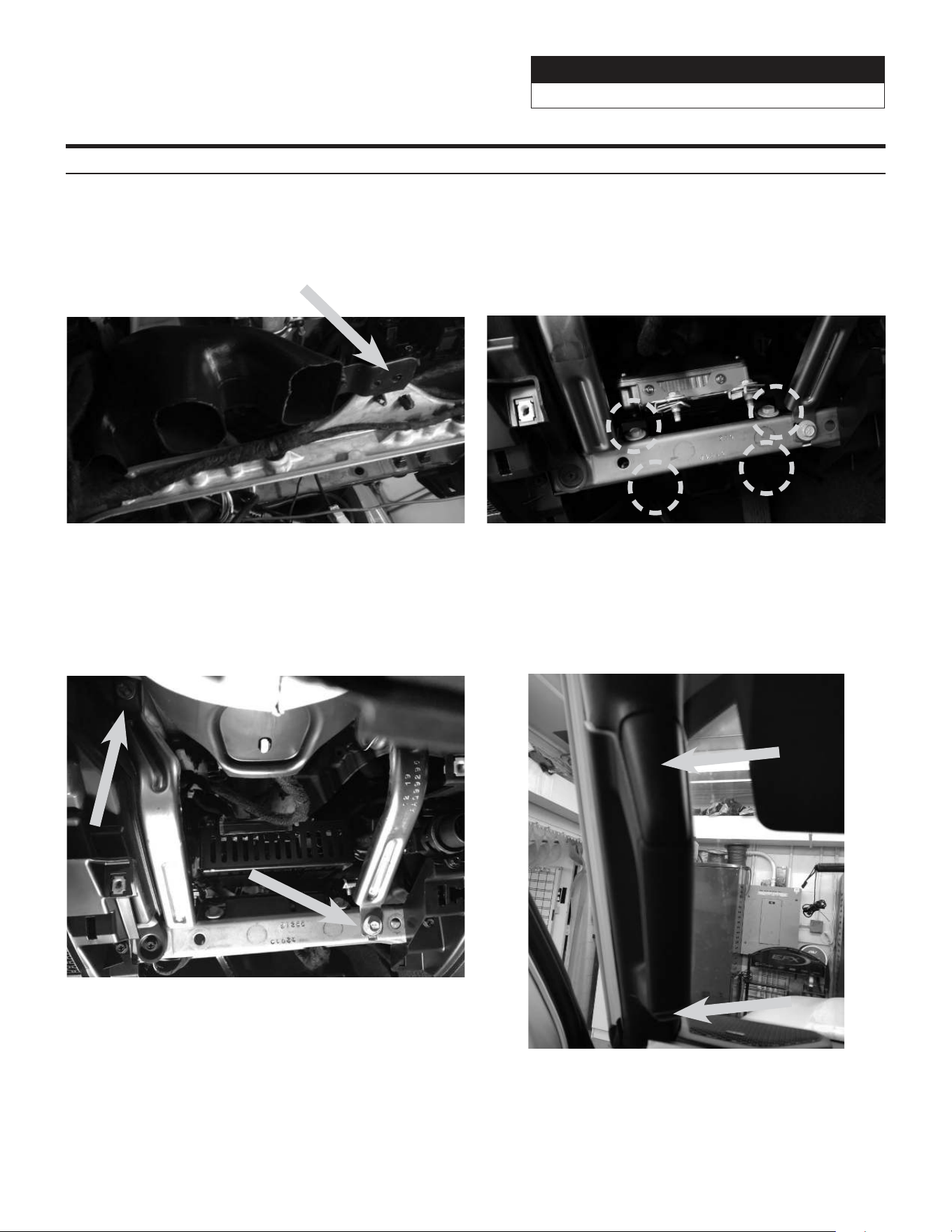
10/29
13 For vehicles with the power inverter remove the
ventilation duct behind the drivers side knee panel
using a panel removal tool to release the one clip
holding it in place. Once the installation of the i509-
WRA-JL tuner is completed the vent can go back
in place.
14 For vehicles with heated seats or the power
inverter the bracket for the module needs to be
removed. Remove the (4) 10mm screws to remove
the bracket. Then remove the (2) 8mm screws lower
and the (2) 10mm screws top to remove the module.
16 Remove the A pillar by removing the (2) 8mm
screws and unclipping the panel. The screws can
be exposed using a panel removal tool.
Factory Unit Disassembly Process (Continued)
15 Remove the two knee panel brackets. Each
bracket is held in by (1) 10mm screw.
Jeep Wrangler
i509-WRA-JL 20220401v1
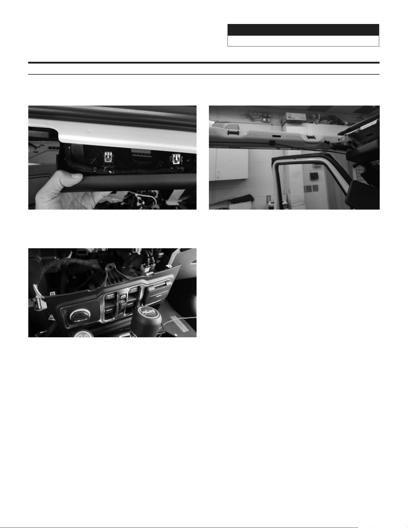
11/29
19 Unclip 7 clips and remove the center media stack.
17 Loosen the clips around the top panel visor area. 18 Remove panel above drivers door going to the B
pillar.
Factory Unit Disassembly Process (Continued)
Jeep Wrangler
i509-WRA-JL 20220401v1
12/29
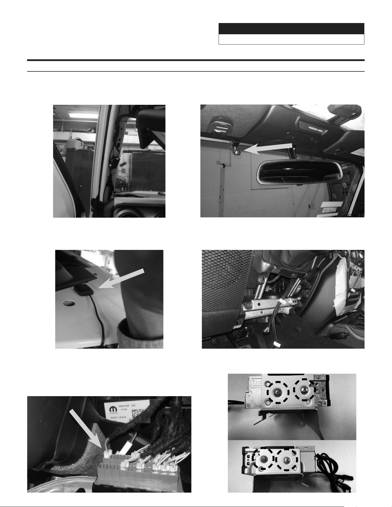
Installation Instructions
1 Run the GPS antenna Bluetooth microphone
cables up the A pillar along the OEM wiring. Route
as shown on the diagram on page 17.
2 Mount the microphone next to the rear view mirror
and run the cable behind the factory panels. Route
as shown on the diagram on page 17.
3 Mount GPS antenna near driver side B-pillar as
illustrated on page 17 and run the cable to the
knee panel.
4 Route radio cables including Radio Main, Sirius XM,
FM, and Aux in main harness and also the display
cable from radio cavity to knee panel.
5 Route vehicle cable in main harness from radio
cavity to glove box and connect it to OBDII
gateway behind the glove box. If the gateway is
fully occupied, unclip 1 connector from it and use
T-harness.
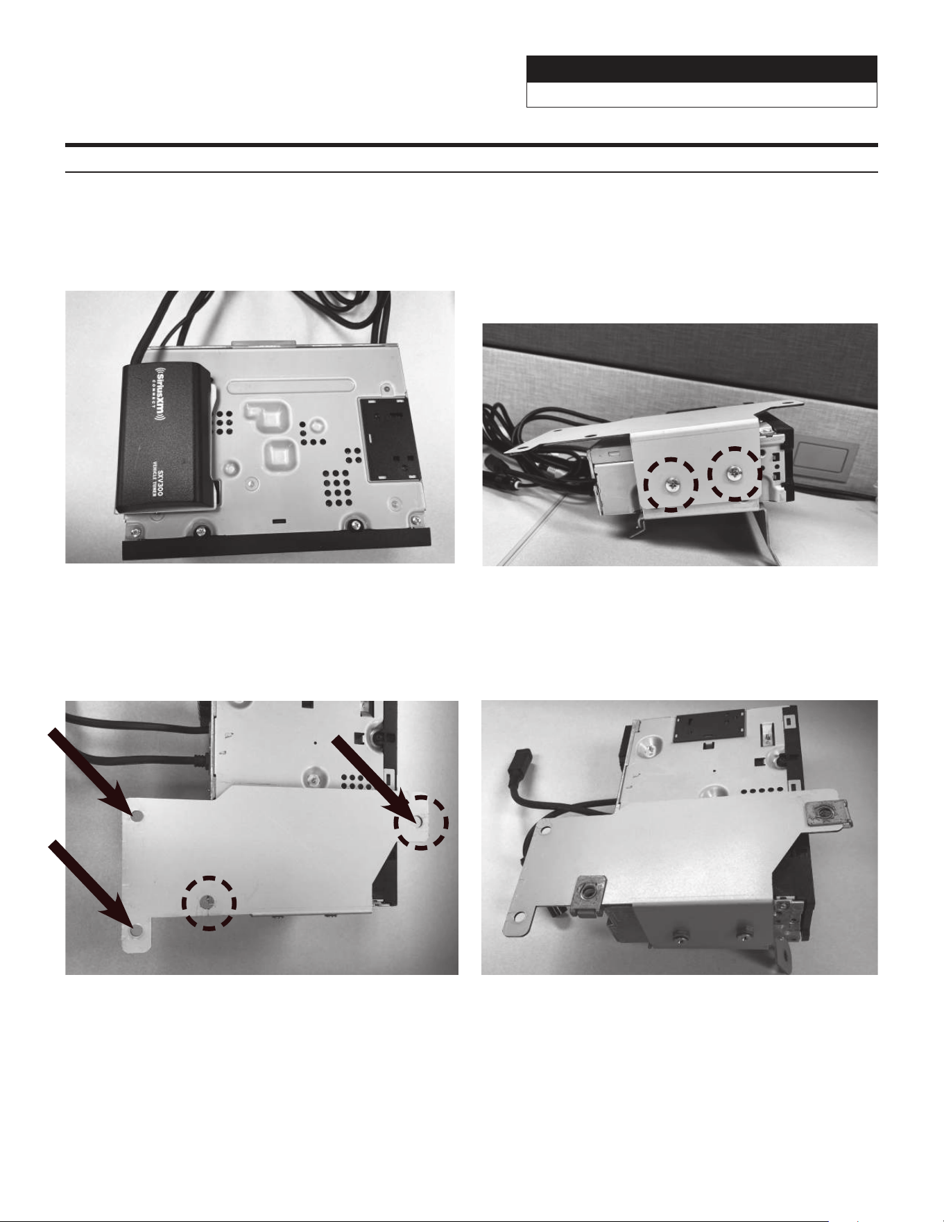
6 Attach tuner bracket to tuner using (4) M5X8LMM
supplied screws.
Jeep Wrangler
i509-WRA-JL 20220401v1
13/29
Installation Instructions (Continued)
7 If you are using the optional SiriusXM tuner, Cable
tie the module on top of the source unit.
8 For vehicles with heated seats or the power
inverter attach the Power Inverter bracket using
the supplied (2) M5X10LMM screws and lock
washers. This will mean you will not use two of the
M5X8LMM screws from the previous page. These
two screws are slightly longer and can make it
through both brackets.
9 Use the factory speed clips from the bracket that
was removed from the vehicle and attach them to
the Power Inverter bracket. For the Wrangler JL
use the 2 holes circled in black. For the Gladiator
JT use the 3 holes pointed out by the arrows.
10 After attaching the factory speed clips this is what
the bracket will look like for the Wrangler JL.
Jeep Wrangler
i509-WRA-JL 20220401v1
14/29
Installation Instructions (Continued)
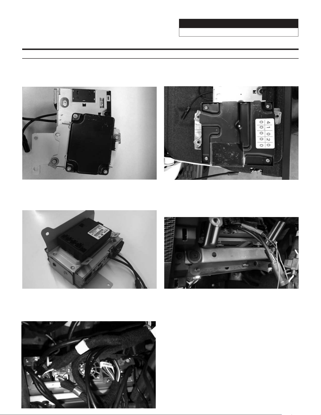
11 Attach the factory Power module to the bracket
using the OEM screws. This is what the power
module will look like for the Wrangler JL.
12 Attach the factory Power module to the bracket
using the OEM screws. This is what the power
module will look like for the Gladiator JT.
14 Use (4) OEM bolts to secure the i509 source
unit tuner bracket to the vehicle. If the vehicle is
equipped with the power inverter it will mount
behind the 2nd cross bar.
15 At the knee panel, connect the main harness,
display harness, GPS antenna, microphone, USB
cable, HDMI, FM adapter, and other adapters to
i509 source unit and secure them.
13 If the vehicle has the heated seat module clip that
into the bottom bracket. The OEM clips on the
module will snap into the bracket.
Jeep Wrangler
i509-WRA-JL 20220401v1
15/29
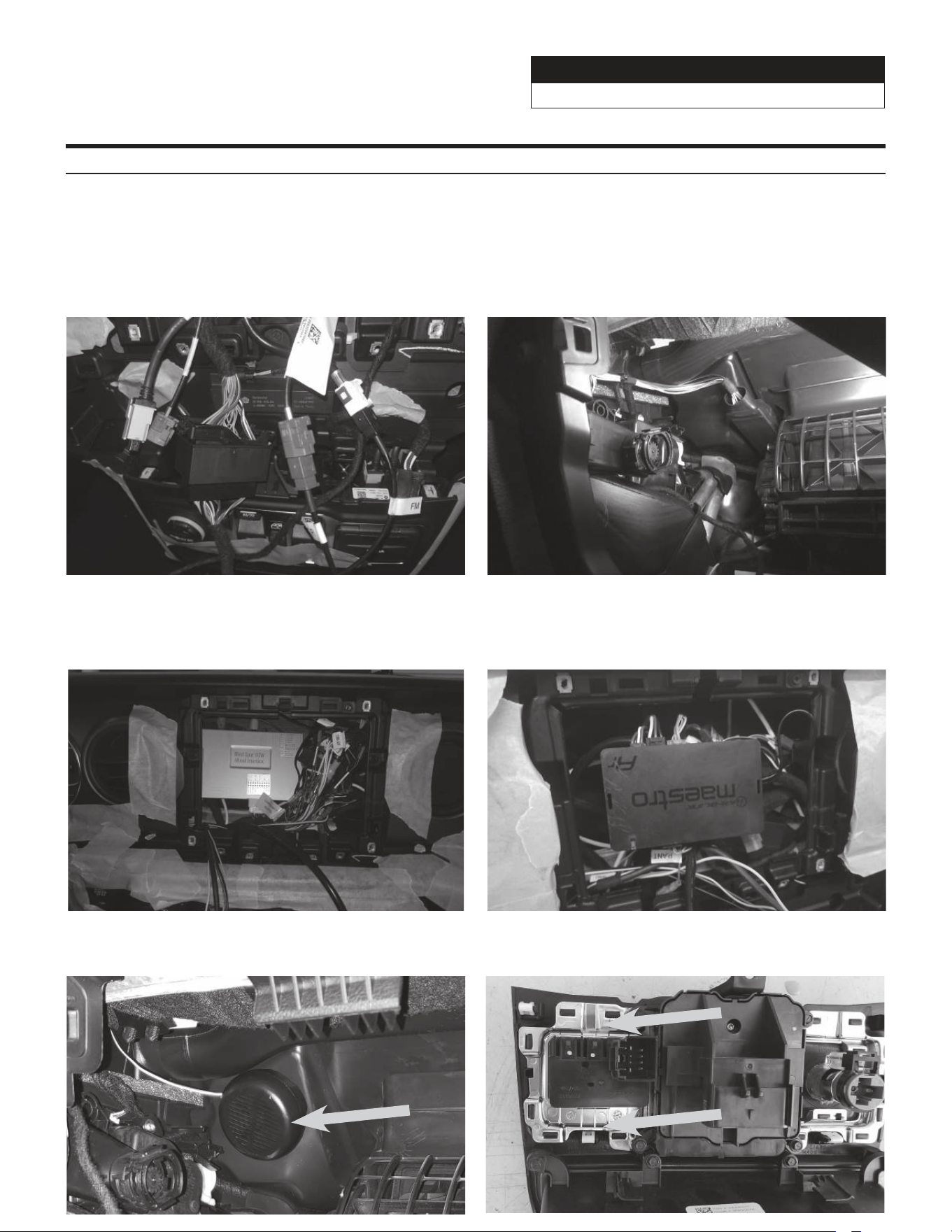
Installation Instructions (Continued)
17 If the vehicle has an OEM amplifier the KCX-
F200INT will need to be purchased separately.
This has 30” of cable so it can be routed behind
the glovebox. It is important to do this so it can
disappate heat properly. The audio settings will
also need to be set to flat as shown on page 29.
18
Connect the camera interface module to the violet
or red factory camera plug and put it in right side
of radio cavity. Dip switch 1 will need to be moved
down for the Gladiator JT.
20 Run chime speaker harness from Maestro module
to behind the glove box and attach there.
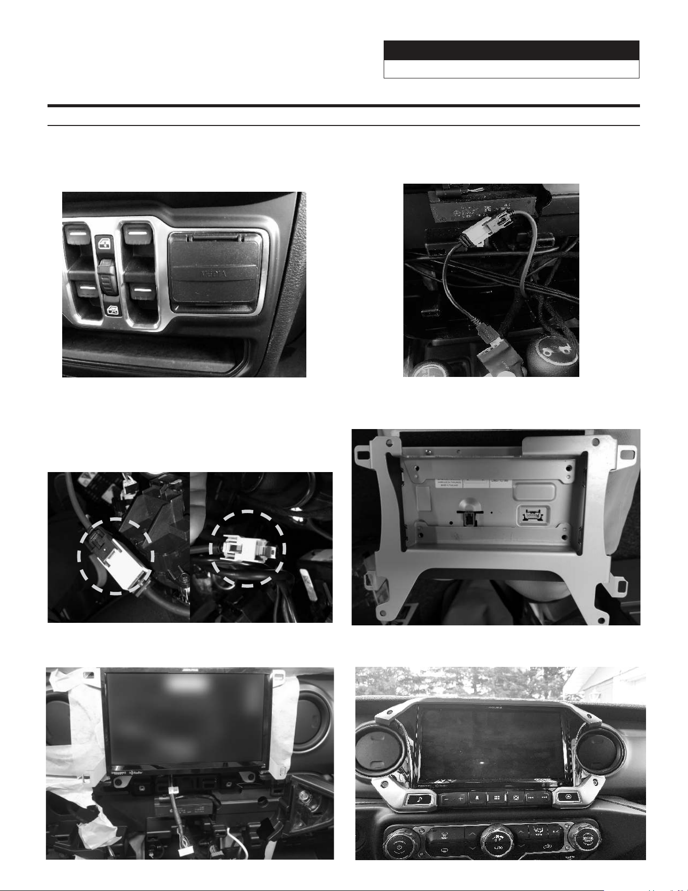
21 Remove the OEM USB from the Center Media
panel by unclipping the clips on the sides.
19 Attach the Maestro to the main harness and tuck it
in left side of radio cavity.
16 At radio cavity, connect the main harness, white
FM adapter, and green SiriusXM antenna, and
other adapters to factory harness and secure them.
Jeep Wrangler
i509-WRA-JL 20220401v1
16/29
Installation Instructions (Continued)
22 Insert the i509 USB HDMI box into the OEM
Center Media panel. Connect the HDMI and the
two USB cables to the source unit as shown on
page 19.
23 Plug in the OEM USB and the USB from the box
to the power adapter. The adaptor needs to be
plugged into the BLACK micro usb.
26 Attach the display and bracket to the vehicle using
the OEM screws from the OEM radio.
25 Apply Anti-Vibration Foam to the top of the display.
Attach the display unit to the display bracket using
the (4) M5X8LMM supplied screws.
27 Plug in the bezel and and reinstall all the factory
panels.
24 WARNING: There are 2 factory micro USB plugs
in the dash behind the media center. One is black
and one is grey. If the supplied adaptor is plugged
into the grey micro USB the factory USB’s will not
charge. When it is plugged into the black plug all
rear USB’s can be used for charging (not data).
Incorrect
Correct
Jeep Wrangler
i509-WRA-JL 20220401v1
17/29
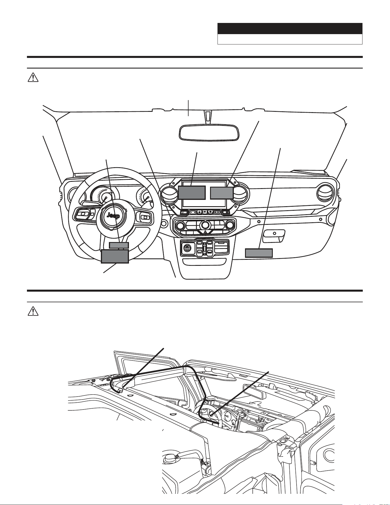
Component Locations
IMPORTANT: Follow the recommended component location shown below. Failure to do so, will result in poor
GPS performance.
Jeep
0
1
2
3
4
5
6
7
RPM
X1000
MPH
0
10
20
30
40
50
MENU CAM
AUDIO
NAV
MEDIA
ENGINE
STAR T
STOP
/////alpine
Add-on Microphone
OBDII Gateway
OEM Camera Module
i509-WRA-JL Source Unit
iDatalink Maestro Module
SAT-Radio Tuner
(Sold Separately)
Harness Route
GPS Antenna Installation
IMPORTANT: Follow the GPS antenna installation procedure shown below. Failure to do so will result in poor
GPS performance for CarPlay, Android Auto, and off-road navigation.
Route from behind
tuner, through
lower dash, and up
the A pillar.
GPS Antenna
Peel the plastic layer
off from the double
side tape of the GPS
antenna and place the
GPS antenna on top of
the driver side roof
frame.
Jeep Wrangler
i509-WRA-JL 20220401v1
18/29
SiriusXM
Antenna
Power Harness
Display Power/Key Harness
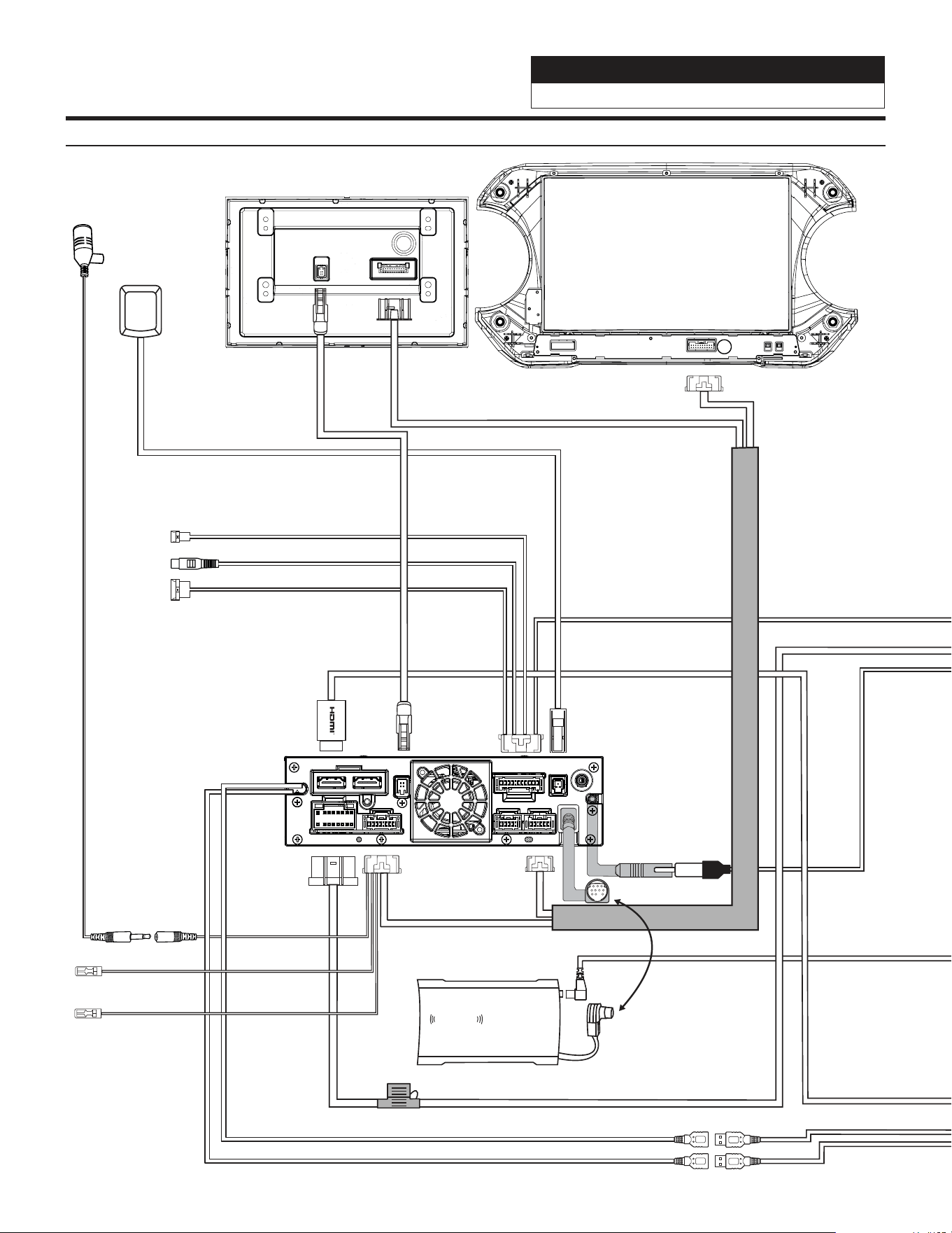
i509
External Microphone
Bluetooth Mic Input
To optional
SiriusXM tuner
(sold seperately)
i509D - Display
SiriusXm
connect
GPS Antenna
PREOUT
USB
CAMERA
ANTENNA
MAIN
REMOTE
SXM
DISPLAY
EX KEY
GPS
OUT
IN
Black USB 2.4A Charge & Passes Data
Gray USB 1.5A Charging Only
Front Camera Direct Input
Dash Cam Video In
Dash Cam Data
To Dash Cam
See Page 10
To Optional
Front Camera
Rear Camera
Direct Input
Note: optional direct to RCA
adapter can be purchased
on www.pacparts.com
This is step 23 on page 16
Aux Remote Out
(Not Used)
Aux Remote In
(Not Used)
Brown
Gray
i509-WRA-JL Wiring Diagram
Jeep Wrangler
i509-WRA-JL 20220401v1
19/29
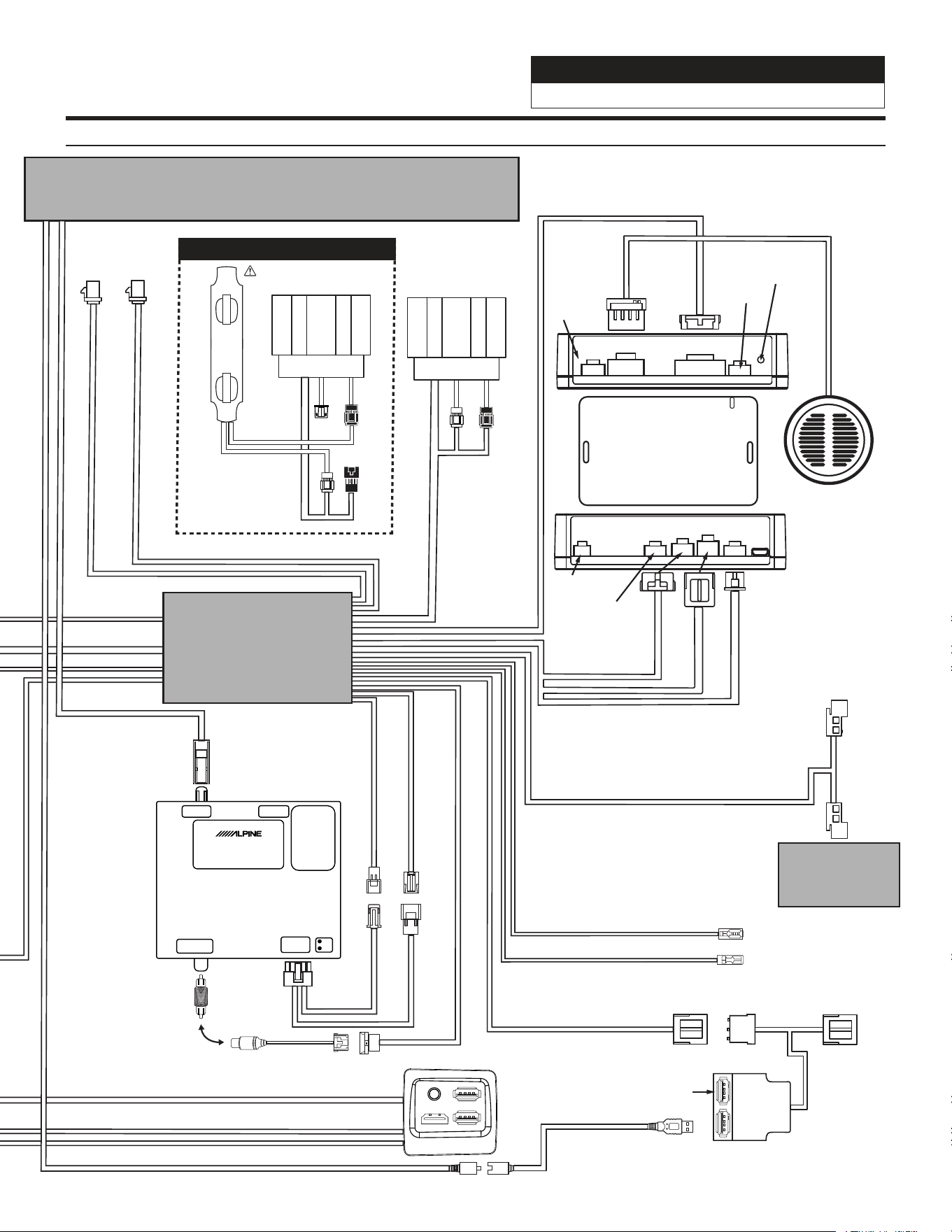
i509-WRA-JL Wiring Diagram Continued
To Vehicle Connectors
iDatalink MAESTRO Module
18-pin Black
Connector
10-pin Green
Connector
(Vehicle signals)
3-pin Black
Connector
(Power)
4-pin Black
Connector
(Data)
To CAN Connector
Blue Power Antenna
Blue/White Amp Turn-on
ACC CAN
Chime Speaker
Power
Speaker
52-pin Connector
18-PinChime10-Pin
3-Pin 4-Pin
3-Pin 4-Pin
Blue
Not
Used
Red
Not
Used
Reset
Button
10-Pin
Front
Rear
Rear
Front
AMPLIFIED VEHICLES
Requires the KCX-F200INT (sold separately)
WARNING!
FM
Antenna
(White)
SXM
Antenna
(Green)
Black
Not
Used
Main Harness
CAN Connector Bank
Aux Power
USB, AUX, HDMI Interface
SGS-BSV1-WJL
FACTORY CAMERA BSV INTERFACE
LVDS INUSB Flash
DIP1:
UP=Wrangler
Down=Gladiator
DIP 2,3,4,5,6,7,8
All up
DIP7:
Down=Firmware Update
VIDEO OUT
Power & CAN
IN
Can1
Can2
Rear
Camera
(Violet
or Red)
USB
HDMI
Rear Camera Direct Input
To Center Console USB Power connector in vehicle
Aux Power pass through
covered by protective cap
CAN pass through
connection in case bank is
full. Otherwise
not used.
Direct Camera Adapter
Camera Power
RCA Coupler
Dip Switch 1 should be up
for the Wrangler and down
for the Gladiator. The rest of
the switches are not used.
Mini USB To USB
Black
Not
Used
This must be plugged into the black micro USB. See page 16 for details
Front
Rear
Rear
Front
Only 2 connections are
necessary for the OEM
amplified system. Front
(White) connects to Front
(White) from tuner. Rear
(Black) connects to Rear
(Black) towards the vehicle.
The other two connections
are not used.
X
X
Not Used
Jeep Wrangler
i509-WRA-JL 20220401v1
20/29
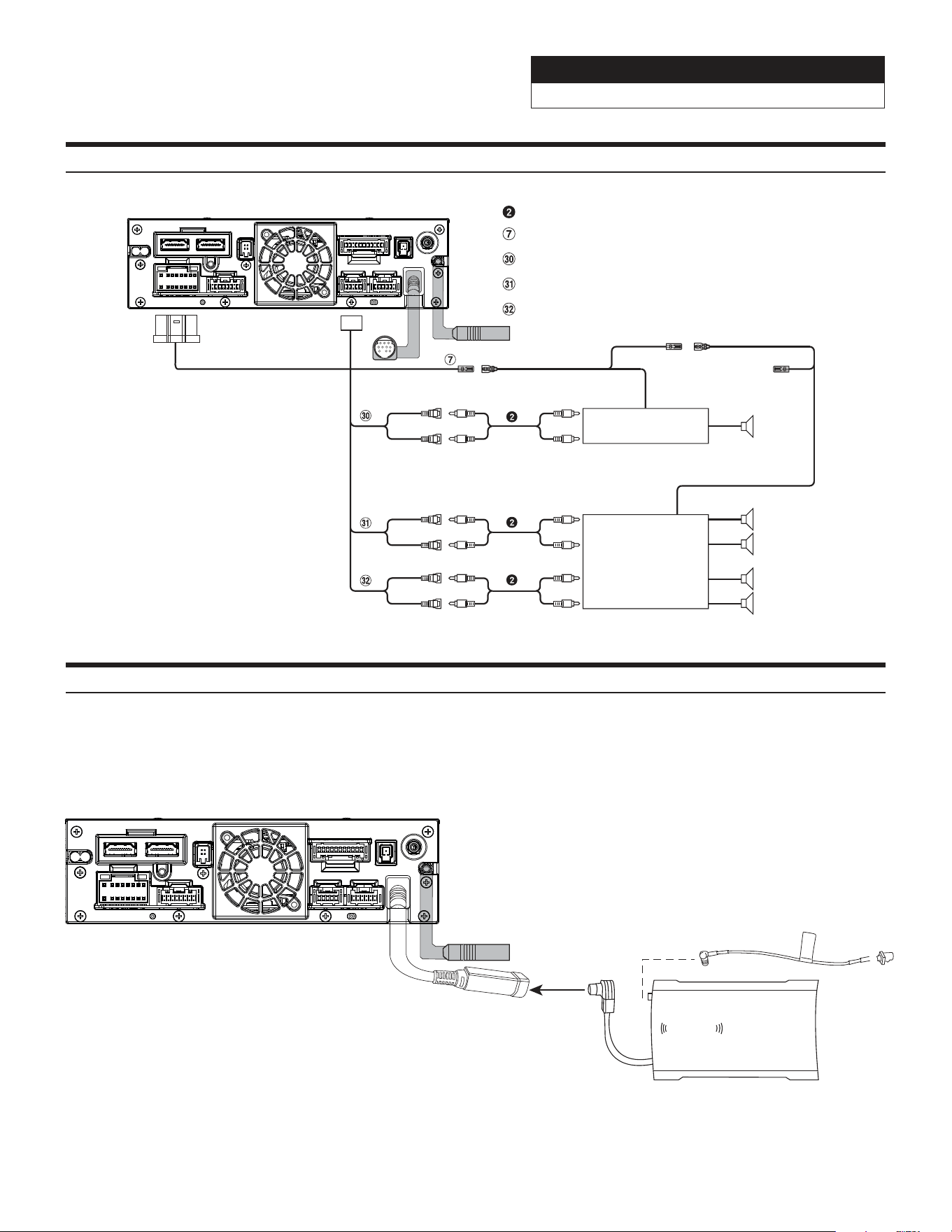
Remote Turn-On Lead (Blue/White)
Subwoofer RCA Connectors
Front Output RCA Connectors
Rear Output RCA Connectors
RCA Extension Cable (sold separately)
(Blue/White)
REMOTE ON
(Blue/White)
Subwoofer
REMOTE
Amplifier for subwoofer
(sold separately)
To subwoofer input terminal
(Red)
(White)
SUBW
FRONT OUT
REAR OUT
To front input terminal
Amplifier 4 ch
(sold separately)
To rear input terminal
Front speaker
Rear speaker
REMOTE ON
(Blue/White)
(Red)
(White)
(Red)
(White)
PREOUT
USB
CAMERA
ANTENNA
MAIN
REMOTE
SXM
DISPLAY
EX KEY
GPS
OUT
IN
Connection Of An External Amplifier
There is no way to integrate the factory SiriusXM tuner. Once the radio is removed, the factory SiriusXM is
removed. As the title states, SiriusXM requires a tuner sold separately. This diagram shows how to integrate the
antenna connection. For vehicles with factory SiriusXM connect the adapter to the factory SiriusXM antenna in the
radio cavity. The factory SiriusXM antenna is located on the passenger side B-pillar. For vehicles without factory
SiriusXM use the antenna that is included with the SXV300 SiriusXM Tuner.
Connecting A SiriusXM Module (Sold Separately)
SiriusXm
connect
PREOUT
USB
CAMERA
ANTENNA
MAIN
REMOTE
SXM
DISPLAY
EX KEY
GPS
OUT
IN
Jeep Wrangler
i509-WRA-JL 20220401v1
21/29
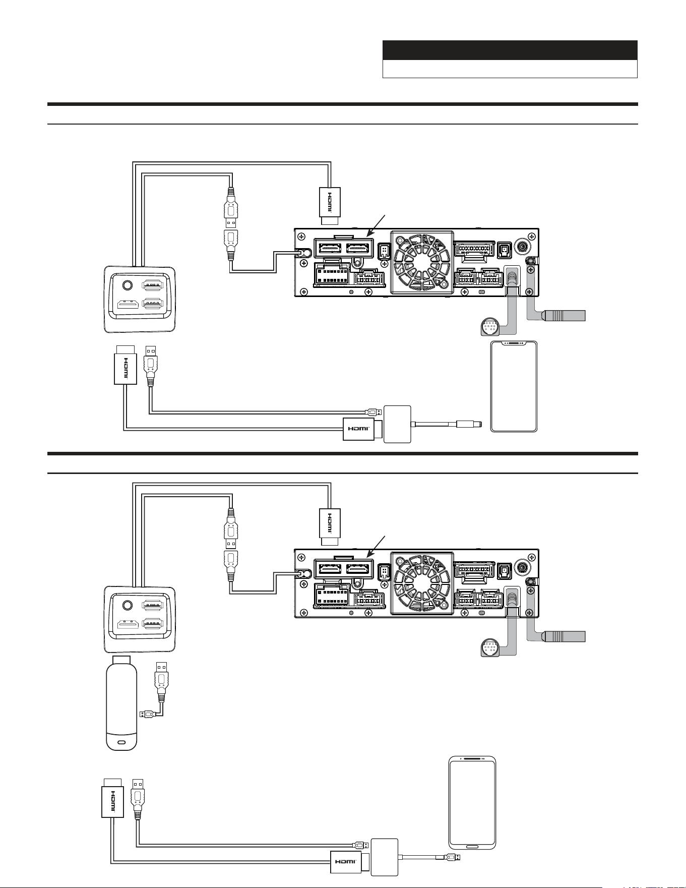
HDMI Input (iPhone)
Lightning To HDMI
adapter needs to be
purchased from Apple.
Third party adapters may
not work
USB
i509-WRA-JL Source Unit
To HDMI In
The black USB is the
only one you can plug
the HDMI adapter into.
That is 2.4A and the
only USB that will power
on the HDMI adapter.
The gray USB will NOT
power on the device. This
also means that you can not
use CarPlay/Android Auto and
HDMI at the same time.
PREOUT
USB
CAMERA
ANTENNA
MAIN
REMOTE
SXM
DISPLAY
EX KEY
GPS
OUT
IN
Most HDMI devices use
copyright protections
which means it can’t be
output from the Source
Unit (a phone would be
an example of this).
iPhone
HDMI Input (iPhone)
For Android users some Android
phones do not have HDMI adapters.
If the phone can cast video
then you can use a Miracast adapter
(for example a Roku Stick
or Amazon Firestick).
Or
Android Phone
Some Android phones may
have a HDMI adapter. That
would be sold separately by
the phone manufacturer. Third
party adapters will not work.
USB
i509-WRA-JL Source Unit
To HDMI In
The black USB is the
only one you can plug
the HDMI adapter into.
That is 2.4A and the
only USB that will power
on the HDMI adapter.
The gray USB will NOT
power on the device. This
also means that you can not
use CarPlay/Android Auto and
HDMI at the same time.
PREOUT
USB
CAMERA
ANTENNA
MAIN
REMOTE
SXM
DISPLAY
EX KEY
GPS
OUT
IN
Most HDMI devices use
copyright protections
which means it can’t be
output from the Source
Unit (a phone would be
an example of this).
HDMI Input (Android)
Jeep Wrangler
i509-WRA-JL 20220401v1
22/29
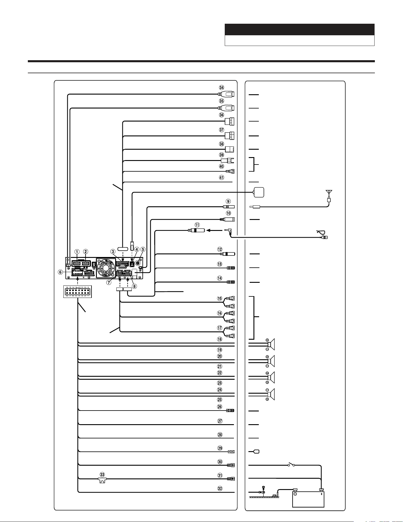
Antenna
Microphone (included)
To amplifier or equalizer
To plus side of the back lamp signal
lead of the car
To the parking brake signal lead
Ignition key
Battery
Power cable
PRE OUT cable
Speakers
Rear Left
Front Left
Front Right
Rear Right
To input terminal of amplifier
when adding an external
amplifier
REAR OUT
REMO
(Blue/White)
REVERSE
(Violet/White)
PARKING BRAKE
(Yellow/Blue)
ACC
(Red)
BATT
(Yellow)
GND
(Black)
(Green)
(Green/Black)
(White)
(White/Black)
(Gray/Black)
(Gray)
(Violet/Black)
(Violet)
SUBW
FRONT OUT
P. ANT
(Blue)
To power antenna
STEERING REMOTE
HDMI-REMO-OUT
AUX-REMO-OUT
To steering remote control
interface
To HDMI Selector Interface
To AUX device (TV Tuner, etc.)
REMOTE cable
(Brown)
(Gray)
MIC IN
To SiriusXM Tuner
To USB flash drive, iPhone or
Android smartphone.
To iPhone or Android smartphone
(For charging only).
To Rear camera
To Front or Side camera
To iDataLink module
To Dash Cam
GPS Antenna (Included)
USB cable 2.4A (Black)
USB cable 1.5A (Gray)
REAR CAMERA
FRONT CAMERA
IDATALINK I/F
LIN
DRIVE RECORDER IN
CAMERA cable
To the vehicle speed pulse line
SPEED SENSOR
(Green/White)
i509-WRA-JL Wiring Diagram
Jeep Wrangler
i509-WRA-JL 20220401v1
23/29
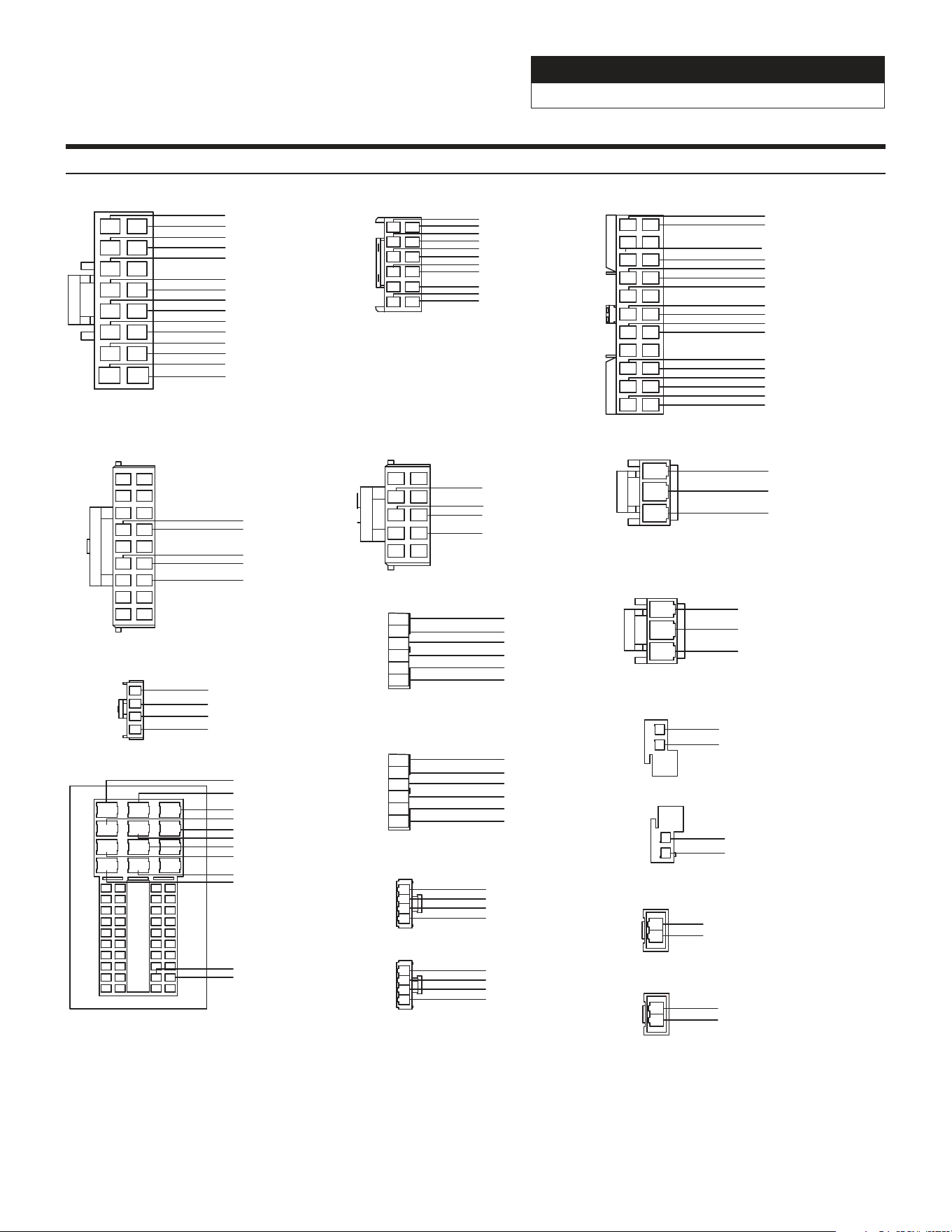
Wire Harness Pin Outs
1
2
3
4
5
6
7
8
9
10
11
12
13
14
15
16
Radio Main
Blue 22AWG
Red 20AWG
Blue/White 22AWG
Orange/White 22AWG
Yellow/Blue 22AWG
Purple 20AWG
Gray 20AWG
Purple/Black 20AWG
Gray/Black 20AWG
Green 20AWG
White 20AWG
Green/Black 20AWG
White/Black 20AWG
Yellow 18AWG
Black 18AWG
1
3
5
7
9
11
2
4
6
8
10
12
Remote Harness
Red/White 22AWG
Brown 22AWG
Aux Power
8
6
43
1 2
9 10
7
5
Radio I/O
Orange/White 22AWG
Green/White 22AWG
Yellow/Blue 22AWG
Blue/White 22AWG
1
2
3
Yellow 18AWG
Red 20AWG
Black 18AWG
Maestro Power
Black 18AWG
Green 20AWG
Green/Black 20AWG
Yellow 18AWG
Brown/Yellow 20AWG
Purple/Black 22AWG
Purple 22AWG
1
2
3
4
Wrangler Radio
Purple 20AWG
Purple/Black 20AWG
Green 20AWG
Green/Black 20AWG
Speaker Harness
1
2
3
4
Gray 20AWG
Gray/Black 20AWG
White 20AWG
White/Black 20AWG
Speaker Harness
15 5
414
13 3
20
19
18
25
24
23
22
30
29
28
27
26
21
35
34
33
40
39
38
37
36
41
50
52
47
32
31
212
111
45
4246
44
43
48
51
49
10
9
8
17 7
616
Gray/Black 20AWG
White/Black 20AWG
White 20AWG
Gray 20AWG
Brown/Red 20AWG
1
2
3
Yellow 18AWG
Red 20AWG
Black 18AWG
1
2
Brown/Yellow 22AWG
Brown/Red 22AWG
CAN
1
2
Red/Brown 22AWG
Yellow/Brown 22AWG
CAN Connector
1
2
Red/Brown 22AWG
CAN Connector
Yellow/Brown 22AWG
1
2
Red 20AWG
Black 20AWG
Camera Power
Yellow 22AWG
Black 22AWG
Black 22AWG
Yellow 22AWG
Brown 22AWG
Brown 22AWG
Brown/White 22AWG
Brown 22AWG
Pink 22AWG
Cam Aux Data
Red 22AWG
Purple 22AWG
Black 22AWG
Black 22AWG
Blue 22AWG
Red/White 22AWG
White 22AWG
Purple 22AWG
White 22AWG
White 22AWG
Black 22AWG
Black 22AWG
1 2
3
9
11
13
15
17
4
8
10
12
14
16
18
5
7
6
19
20
21
22
Blue/White 22AWG
Black/White 22AWG
Black/White 22AWG
Blue/White 22AWG
1
2
3
4
5
6
Front Camera
Black 22AWG
Black 22AWG
Red 22AWG
Blue 22AWG
Black 22AWG
White 22AWG
Data SWC
12
11
13
14
16
15
17
18
1
2
4
3
6
5
8
7
9
10
Brown/Red 22AWG
Brown/Yellow 22AWG
Red/Brown 22AWG
Yellow/Brown 22AWG
Yellow/Black 22AWG
4
1
2
3
iDatalink
Blue 22AWG
White 22AWG
Black 22AWG
Red 22AWG
1
2
3
4
5
6
Rear Camera
Black 22AWG
Black 22AWG
Red 22AWG
Blue 22AWG
Black 22AWG
White 22AWG
Green/White 22AWG
Jeep Wrangler
i509-WRA-JL 20220401v1
24/29
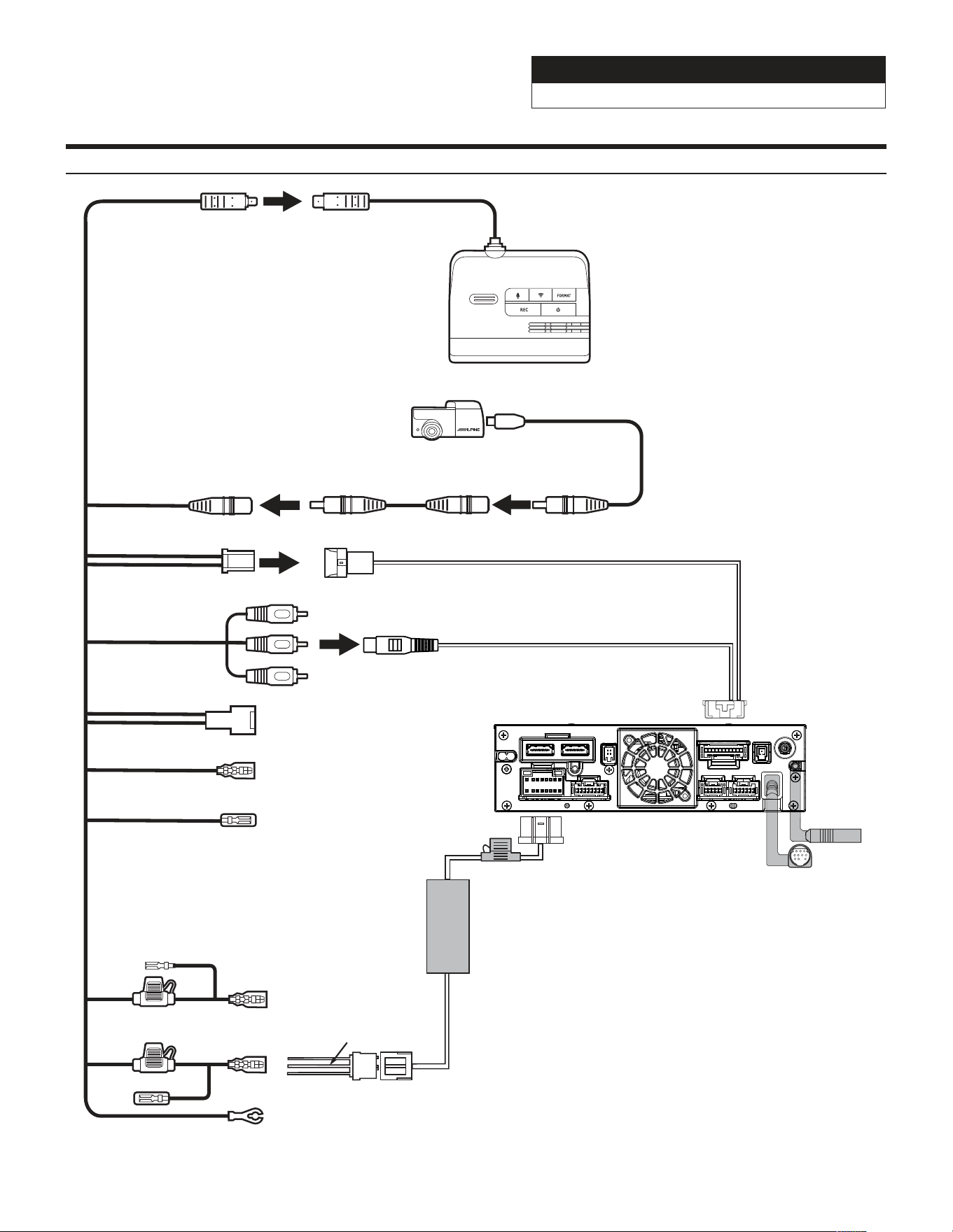
Connection Of DVR-C320R/C310R (Sold Separately)
PREOUT
USB
CAMERA
ANTENNA
MAIN
REMOTE
SXM
DISPLAY
EX KEY
GPS
OUT
IN
i509 Source Unit
Power Harness
AUX Power
3-pin Black Connector
Black - Ground
Yellow -12V+
Red - Acc 12V+
Main Harness
Yellow
Red
Black
Cut the terminals.
Solder and heat shrink
to AUX Power Connector.
Remocon Out
Remocon In
Lin Cable
Lin Cable
F Cam
R Cam
Hardwiring Cable
DVR-C320R/C310R
Dash Cam Video In
Dash Cam Data
Not Used
Rear Camera Cable
Rear Camera
Extension Cable
Rear Camera
Not Used
Not Used
Jeep Wrangler
i509-WRA-JL 20220401v1
25/29
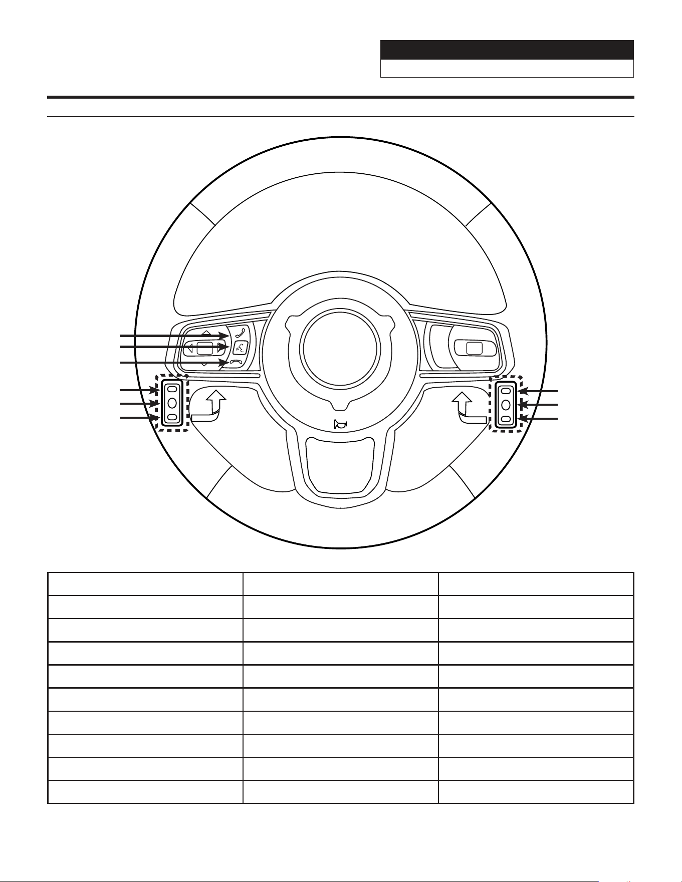
Steering Wheel Configuration
Button Press Once Press And Hold
Seek Up Track + None
Seek Down Track - None
Next Preset Preset & Folder + Preset & Folder -
Voice Voice Or Siri None
Off Hook Answer Call None
On Hook Hang Up & Reject Call None
Volume Up Volume + None
Volume Down Volume - Attenuation On/Off
Source Source/Camera View None
OK
Seek Up
Preset Up
Seek Down
Volume Up
Volume Down
Source
Off Hook
Voice
On Hook
Jeep Wrangler
i509-WRA-JL 20220401v1
26/29
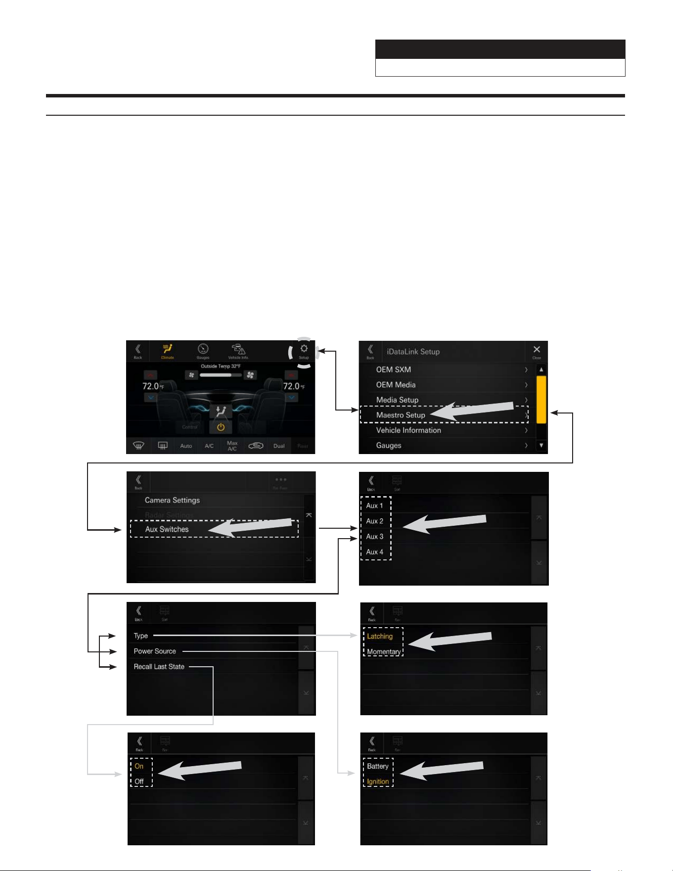
Setting Up OEM Aux Switches
1 Once in the setup menu (see page 28) go to the Maestro screen and select SETUP.
2 Select MAESTRO SETUP then VEHICLE FEATURES (not pictured). (Note this path in the settings can vary
slightly with different Maestro firmwares).
3 Select AUX SWITCHES.
4 Select the switch that you would like to edit (AUX 1, AUX 2, AUX 3, or AUX 4).
5 Select the setting you would like to edit (TYPE, POWER SOURCE, or RECALL LAST STATE).
6 TYPE can be set for either LATCHING or MOMENTARY. LATCHING means that when the switch is selected it
will stay on until the switch is pressed again. MOMENTARY will only keep the switch on as long as the button
is held in.
7 RECALL LAST STATE when set to ON the state of the switch is retained across ignition cycles.
8 POWER SOURCE menu can be set for either BATTERY or IGNITION. BATTERY means the switch has power to
it at all times. IGNITION means it has power only when the vehicle is on.
3 4
5 6
7 8
1 2
Jeep Wrangler
i509-WRA-JL 20220401v1
27/29
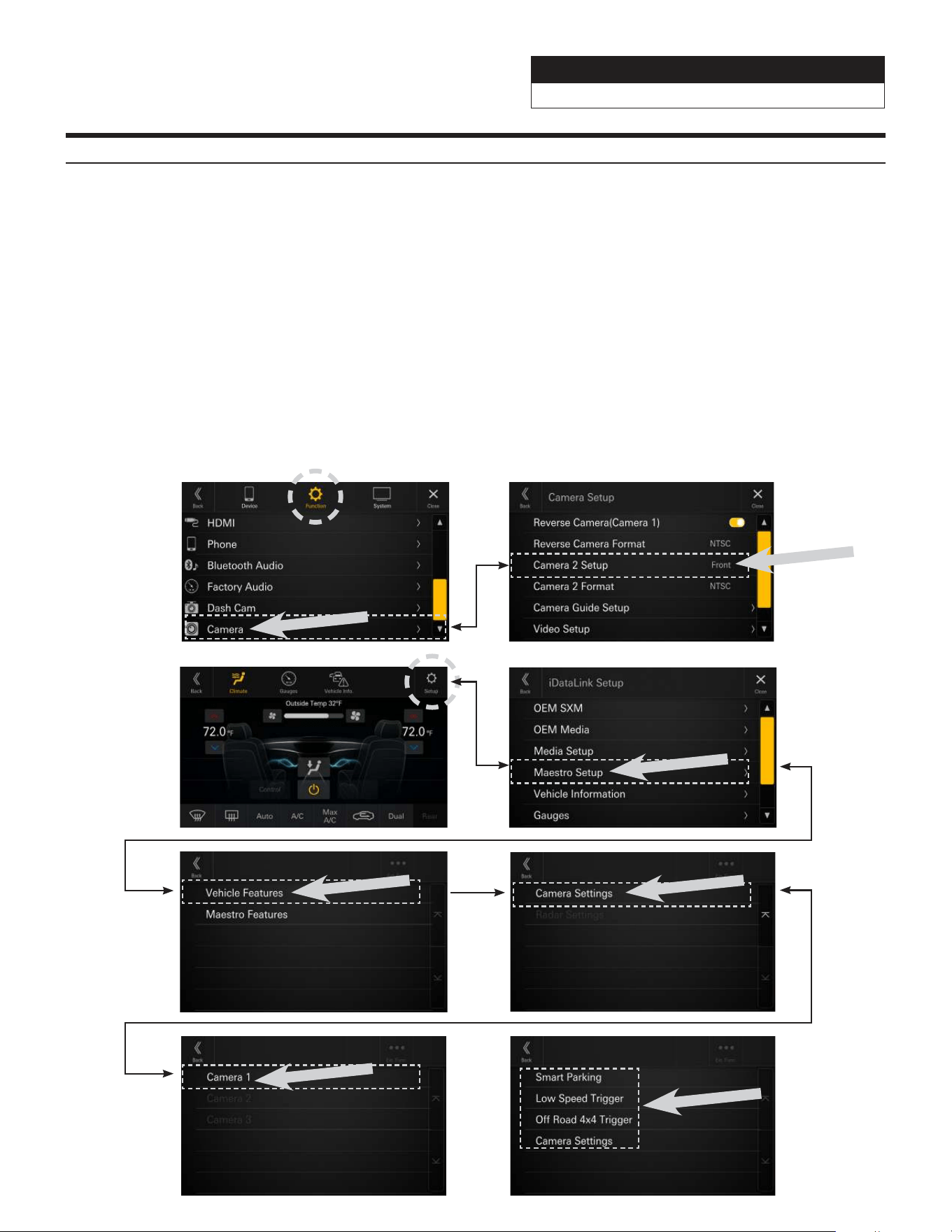
Setting Up Advanced Camera Features
1 Once in the setup menu (see page 28) select FUNCTION and then CAMERA.
2 Select CAMERA 2 SETUP. The camera 2 input needs to be set to FRONT or SIDE. This will let the Maestro
module know the second camera is active and that will enable the CAMERA SETTINGS in the Maestro Setup
Menu.
3 In the Maestro screen select SETUP.
4 Select MAESTRO SETUP. (Note this path in the settings can vary slightly with different Maestro firmwares).
5 Select VEHICLE FEATURES.
6 Select CAMERA SETTINGS.
7 Select Camera Assignment then CAMERA 1. The available options are FRONT CAMERA, RIGHT LANE WATCH
CAMERA, and LEFT LANE WATCH CAMERA.
8 Once CAMERA 1 is set the corresponding camera settings will then be available.
1 2
3 4
5 6
7 8

Jeep Wrangler
i509-WRA-JL 20220401v1
28/29
Set Up Guide
1 Turn the vehicle’s Ignition switch to ACC.
2 Turn ON the i509-WRA-JL by pressing any key.
3 Select the user language and press OK.
4 To get into the settings the parking brake sequence needs to be done. Engage the parking brake, release
the parking brake, and engage the parking brake again.
5 Vehicle information- Set the desired gauge information. (HOME/VEHICLE INFO/SETUP).
6 To turn on rear camera in the system menu. (HOME/FUNCTION/CAMERA/REVERSE CAMERA).
7 If the vehicle is equipped with the factory accessory switches set those up. See page 27 for details. (MENU/
FACTORY SYSTEM SETUP/MAESTRO MODULE/VEHICLE FEATURES/AUX SWITCHES).
8 For vehicles with an OEM amplifier the Time Correction, P-EQ, and X-Over must be set flat. (HOME/UPPER
CENTRAL BUTTON ON SCREEN).
Troubleshooting Guide
Symptom Possible Cause Remedy
1
iPhone not working with
HDMI.
Not using Apple HDMI to Lightning
adapter.
Purchase the HDMI to Lightning adapter
directly from Apple. Not all 3rd party
adapters work the same.
Didn’t plug USB power into a 2A
source.
A 2A USB power source must be used to
power on the device.
2
Android phone is not working
with HDMI.
Using incorrect HDMI adapter.
If the phone has the feature to use an HDMI
adapter it must be the one purchased from
the manufacturer of the phone, not a third
party adapter.
Miracast or HDMI adapter isn’t
plugged into a 2A source.
A 2A USB power source must be used to
power on the device.
Miracast adapter has resolution
settings that are too high.
Plug the adapter into another monitor (for
example a television in the home) and reduce
the resolution settings.
3
iDatalink website says serial
number is invalid.
Incorrect serial number is being
used.
In the i509-WRA-JL settings confirm the
serial number. MENU/SETUP/GENERAL/
ABOUT.
Serial number may not be in
iDatalink database.
Call ADS at 1-866-427-2999 and verify.
4
Headunit will not turn on.
Incorrect serial number was used
when flashing maestro.
Flash Maestro with correct serial number.
4 pin Maestro data cable is
disconnected or damaged.
Check for proper connection or
disconnected pins.
OBD2 cable is not plugged in. Connect OBD2 connector to the OBD2 port.
Monitor, key-harness or main
harness are not connected.
Check for proper connection or
disconnected pins.

Jeep Wrangler
i509-WRA-JL 20220401v1
29/29
Troubleshooting Guide Continued
Symptom Possible Cause Remedy
5 No output from RCA’s
Maestro module is flashed for
amplified system.
Re-flash module for non-amplified system.
6
Cannot enter SETTINGS
MENU.
Vehicle is in motion or parking
brake is not engaged.
With vehicle in (P)PARK engage the parking
brake. Release the parking brake and
engage the parking brake a second time, as
shown in the Setup Guide on page 28.
7
Sound mutes when vehicle is
shifted into reverse.
Mute on reverse is turned on in the
SOUND menu.
Change Mute on reverse to off.
8
Only the front speakers are on
for SXM Radio.
SXM Tuner has not been activated. Activate SXM Tuner.
9
The vehicle is incorrectly
positioned on the Navigation
display.
Poor GPS signal.
Ensure the recommeded GPS antenna route
was used. See page 17.
10
CarPlay, Android Auto, or
off-road navigation map
positioning issues.
GPS antenna is positioned
incorrectly.
GPS antenna is obstructed and doesn’t have
line of sight to the sky. Perform a factory
reset. The unit will automatically recalibrate.
11
CarPlay, Android Auto, or
off-road navigation vehicle
position icon heading in
wrong direction
Reverse Signal is not connected or
not reliable.
Ensure that Reverse wire is connected. Also
ensure that no 3rd party interface module(s)
interfere with the Reverse Signal. The head
unit uses the Reverse Signal to achieve
optimal positioning performance.
12
iPhone or Android phone is
not recognized
when connected to the
USB cable.
Loose or disconnected USB cable.
Check the USB connection behind
the headunit.
Non-compatible cable.
Use the cable supplied with the
iPhone or Android phone. Third party
adapters and long extensions may not work.
Only use USB extension that came with the
head unit.
Dirty charging port on phone. Clean charging port.
Wrong USB port used.
The OEM USB’s are only meant for charging.
They can’t transfer data. The only one that
can is the bottom port of the USB, AUX,
HDMI interface that is included.
13
Volume controls on bezel and
steering wheel controls do not
work.
The setting for External Processor
was turned on.
That setting should only be checked when
using an external sound processor. When
there isn’t one being used in the audio
system it needs to be in the default setting
of off. MENU/SETUP/SYSTEM/EXTERNAL
ACCESSORIES/EXTERNAL AUDIO
PROCESSOR/OFF
14 OEM USB’s not charging.
The wrong micro USB was plugged
into the USB power adapter.
There are 2 factory micro USB plugs in
the dash behind the media center. One
is black and one is grey. If the supplied
adaptor is plugged into the grey micro
USB the factory USB’s will not charge.
Make sure the black USB is plugged into
the power adapter. See pages 16 and 19
for details.
