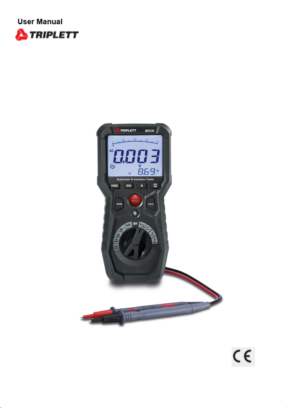
Operating Instruction for
True RMS Multimeter &
Insulation Tester
Please read this manual before switching the unit on.
Important safety information inside.
MG530
Insulation Tester and Digital Multimeter

3
True RMS Multimeter & Insulation Tester
Page
4
4
4
5
6
6
7
8
8
9
10
11
11
12
13
14
15
16
17
17
18
18
18
19
19
22
22
Content
1.Precautions and Safety Measures..................................................
1-1.International Safety Symbols...................................................
1-2.Safety Information...................................................................
............................................................ 1-3.Input Protection Limits
.......................... 1-4.Per IEC1010 Overvoltage Installation Category
1-5.Electromagnetic Environment...................................................
2.General Description.......................................................................
3.Description...................................................................................
3-1.Meter Description....................................................................
3-2.Description of the Display........................................................
3-3.Button Function.......................................................................
4.Operating Instructions...................................................................
4-1.DC/AC+DC Voltage Measurement..............................................
4-2.AC Voltage Measurement..........................................................
4-3.Low Z AC/DC Voltage Measurement..........................................
4-4.Resistance Measurement and Continuity Test...........................
4-5.AC Current (with Current Transducer) Measurement..................
4-6.Insulation Resistance Measurement.........................................
5. Maintenance.................................................................................
5-1. The Internal Battery.................................................................
5-2.Replacement of Internal Fuses.................................................
5-3.Cleaning the Instrument...........................................................
5-4.End of Life...............................................................................
6.Specifications...............................................................................
6-1.Technical Specifications...........................................................
6-2.General Specifications.............................................................
7.Accessories Provided....................................................................
4
True RMS Multimeter & Insulation Tester
1.Precautions and Safety Measures
• The instrument has been designed in compliance with directive IEC/EN61010-1 relevant to electronic measuring
instruments.
• For your safety and in order to prevent damaging the instrument, please carefully follow the procedures described
in this manual and read all notes preceded by symbol with the utmost attention.
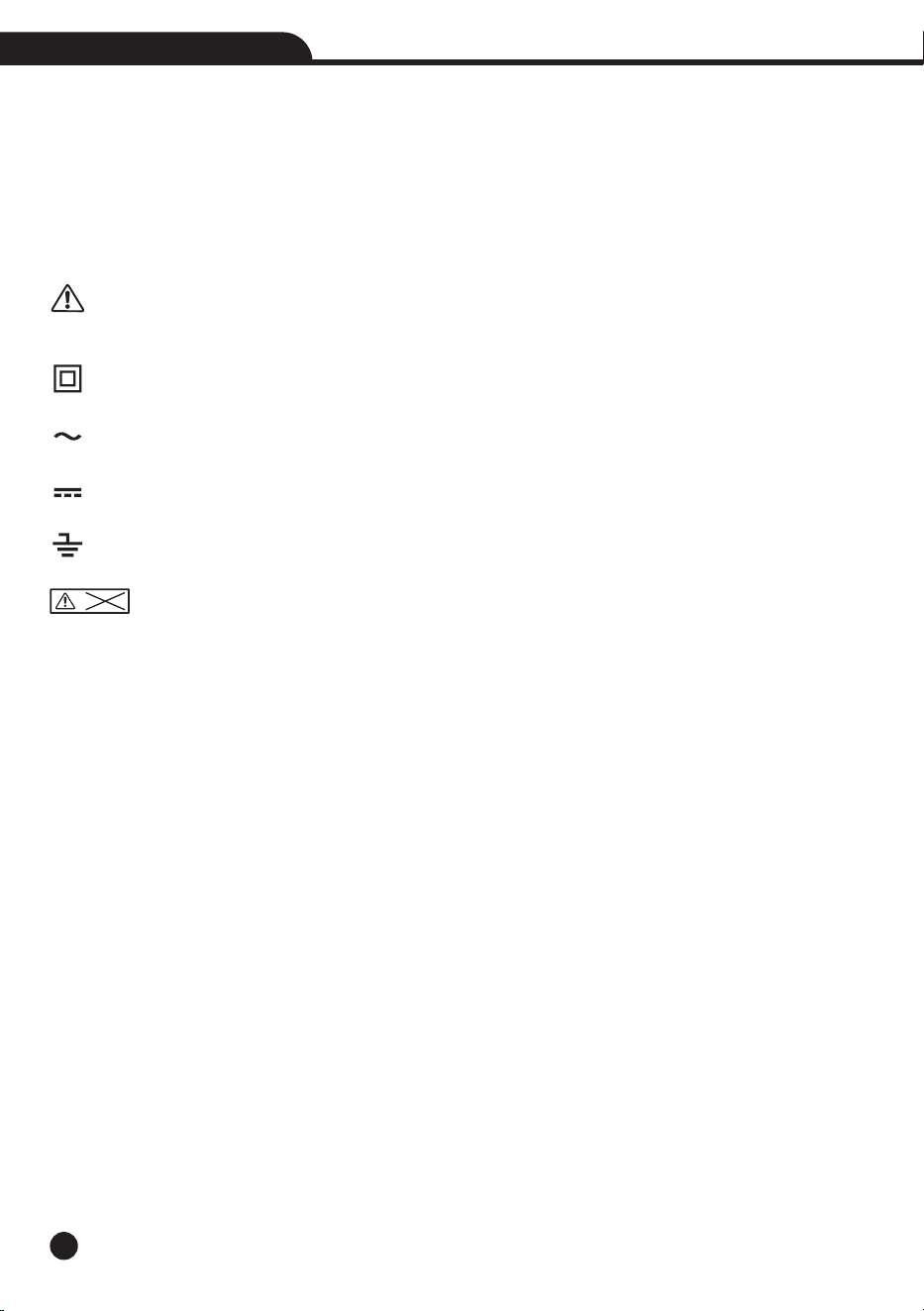
1-1.International Safety Symbols
WARNING: observe the instructions given in this manual; improper use could damage the instrument or its
components.
Double-insulated meter
AC voltage or current
DC voltage or current
Connection to earth
DO not test Voltage more than 550V
1-2.Safety Information
This meter has been designed for safe use, but must be operated with caution, the rules listed below must be
carefully followed for safe operation.
• Do not carry out any measurement in humid environments.
• Do not carry out any measurements in case gas, explosive materials or flammables are present, or in dusty
environments.
• Avoid any contact with the circuit being measured if no measurements are being carried out.
• Avoid any contact with exposed metal parts, with unused measuring probes, circuits, etc.
• Do not carry out any measurement in case you find anomalies in the instrument such as deformation, breaks,
substance leaks, absence of display on the screen, etc.
• Before each use, verify meter operation by measuring a known voltage.
• Do not use the meter on a circuit with voltages that exceed the category based rating of this meter.
• Do not use the meter during electrical storms or in wet weather.
• Do not use the meter or test leads if they appear to be damaged.
• Use Only with CAT IV rated test leads.
• Ensure meter leads are fully seated, and keep fingers away from the metal probe contacts when making
measurements.
• Do not open the meter to replace batteries while the probes are connected.
• Use caution when working with voltages above 25V AC RMS or 60V DC, such voltages pose a shock hazard.
• To avoid false readings that can lead to electrical shock, replace batteries when a low battery indicator appears.
>550V

5
True RMS Multimeter & Insulation Tester
• Do not attempt to measure resistance or continuity on a live circuit.
• Make sure the circuit under test does not include components that can be damaged by 1000VDC; such devices
include power factor correction capacitors, low voltage mineral insulated cables, electronic light dimmers, and
ballast/starters for fluorescent lamps.
• Do not perform insulation resistance testing or earth-bond resistance testing if voltage is present on parts of an
installation or equipment under test, circuits under test (except for voltage measurements) must be de-energized
and isolated before connections are made.
• Circuit connections must not be touched during a test, accidental contact with conductors could result in electrical
shock.
• After insulation resistance testing, make sure the circuit is fully discharged before removing test leads, LCD
should read close to zero volts.
• Always adhere to local and national safety codes.
• Use personal protective equipment to prevent shock and arc blast injury where hazardous live conductors are
exposed.
• Never apply voltage or current to the meter that exceeds the specified maximum.
• Use extreme CAUTION when working with high voltages.
• Do not measure voltage if the voltage on the “COM” input jack exceeds 1000V above earth ground.
• Never connect the meter leads across a voltage source while the function switch is in the current, resistance or
diode mode, doing so can damage the meter.
• Always discharge filter capacitors in power supplies and disconnect the power when making resistance or diode
tests.
• Always turn off the power and disconnect the test leads before opening the covers to replace the fuse or batteries.
• Never operate the meter unless the back cover and the battery and fuse covers are in place and fastened securely.
• If the equipment is used in a manner not specified by the manufacturer, the protection provided by the equipment
may be impaired.
1-3.Input Protection Limits
Function
V DC or V AC
Electrical Resistance and Continuity
3000A AC
Insulation Resistance Measurement
AC+DC Measurement
Surge Protection: 8kV peak per IEC 61010
Maximum Input
1000VDC/AC rms
500mA 1000V fast acting fuse
1000V DC/AC rms
550V DC/AC rms
1000VDC/AC rms

6
True RMS Multimeter & Insulation Tester
1-4.Per IEC1010 Overvoltage Installation Category
Overvoltage Category I: Equipment of Overvoltage Category I is equipment for connection to circuits in which•
measures are taken to limit the transient overvoltages to an appropriate low level.
Note: Examples include protected electronic circuits.
Overvoltage Category II: Equipment of Overvoltage Category II is energy-consuming equipment to be supplied•
from the fixed installation.
Note: Examples include household, office, and laboratory appliances.
Overvoltage Category III: Equipment of Overvoltage Category III is equipment in fixed installations.•
Note: Examples include switches in the fixed installation and some equipment for industrial use with permanent
connection to the fixed installation.
Overvoltage Category IV: Equipment of Overvoltage Category IV is for use at the origin of the installation.•
Note: Examples include electricity meters and primary over-current protection equipment.
1-5.Electromagnetic Environment
IEC EN 61326-1, this equipment meets requirements for use in basic and controlled electromagnetic environments
like residential properties, business premises, and light-industrial locations

7
True RMS Multimeter & Insulation Tester
2.General Description
• The instrument carries out the following measurements:
DC voltage
AC, AC+DC TRMS Voltage
LPF, Low Pass Filter
Low Z AC/DC Voltage
30A, 300A, 3000A AC TRMS Current with Current Transducer
Resistance and Continuity Test
Frequency
Insulation Tester
• Each of these functions can be selected by means of the appropriate switch.
• The instrument is also equipped with function keys, analogue bargraph and LCD display.
• The instrument is also equipped with an Auto Power OFF function which automatically switches off the instrument
after a certain (programmable) idling time.
8
True RMS Multimeter & Insulation Tester
INSULATION
>550V
COM
CAT IV 600V
CAT III 1000V
V Hz
RISO
LoΩ
FUSE
500mA
15 16
17
18 19
MODE HOLD
TEST
RANGE ZERO
MAX
MIN
OFF
V
Hz
LO
LoΩ
MΩ
125V
MΩ
250V
MΩ
500V
MΩ
1000V
V
Lo Z
3000A
V
AC+DC
Auto Power Off
True RMS Multimeter & Insulation Tester
1
2
3
4
5
6
7
8
9
10
11
12
13
14
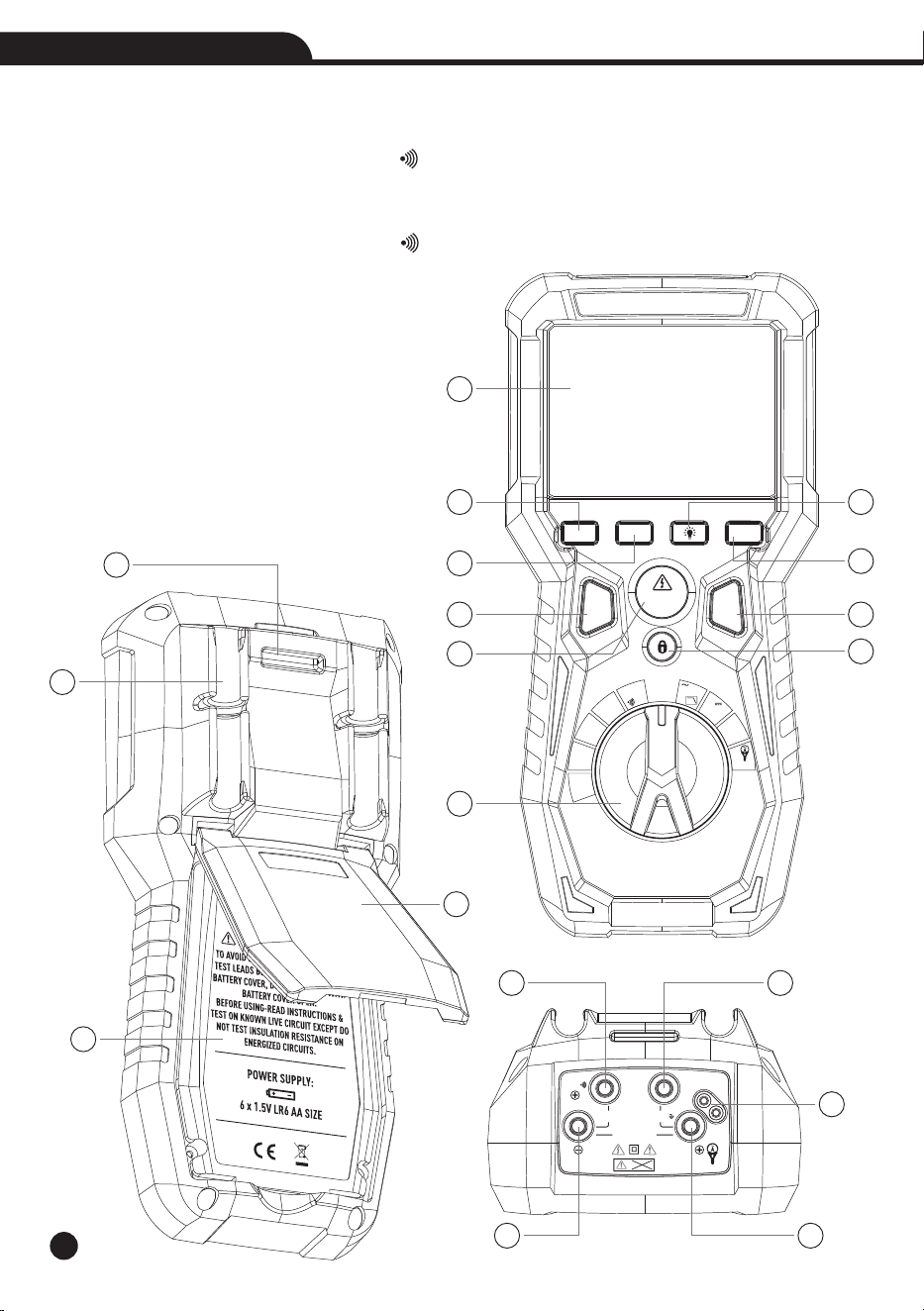
3.Description
3-1.Meter Description
1-LCD Display
2-RANGE Button
3-ZERO Button
4-Backlight Button
5-MAX/MIN Button
6-MODE Button
7-TEST Button
8-HOLD Button
9-LOCK Button
10-Rotary Selector Switch
11-Lanyard Hole
12-Test Lead Holders
13-Battery Cover
14-Tilt Stand
15-Input Terminal / +Ω
16-Input Terminal COM
17-Input Terminal Test Lead
18-Input Terminal / -/INSULATION-Ω
19-Input Terminal V/Hz/3000A/
INSULATION+
9
True RMS Multimeter & Insulation Tester
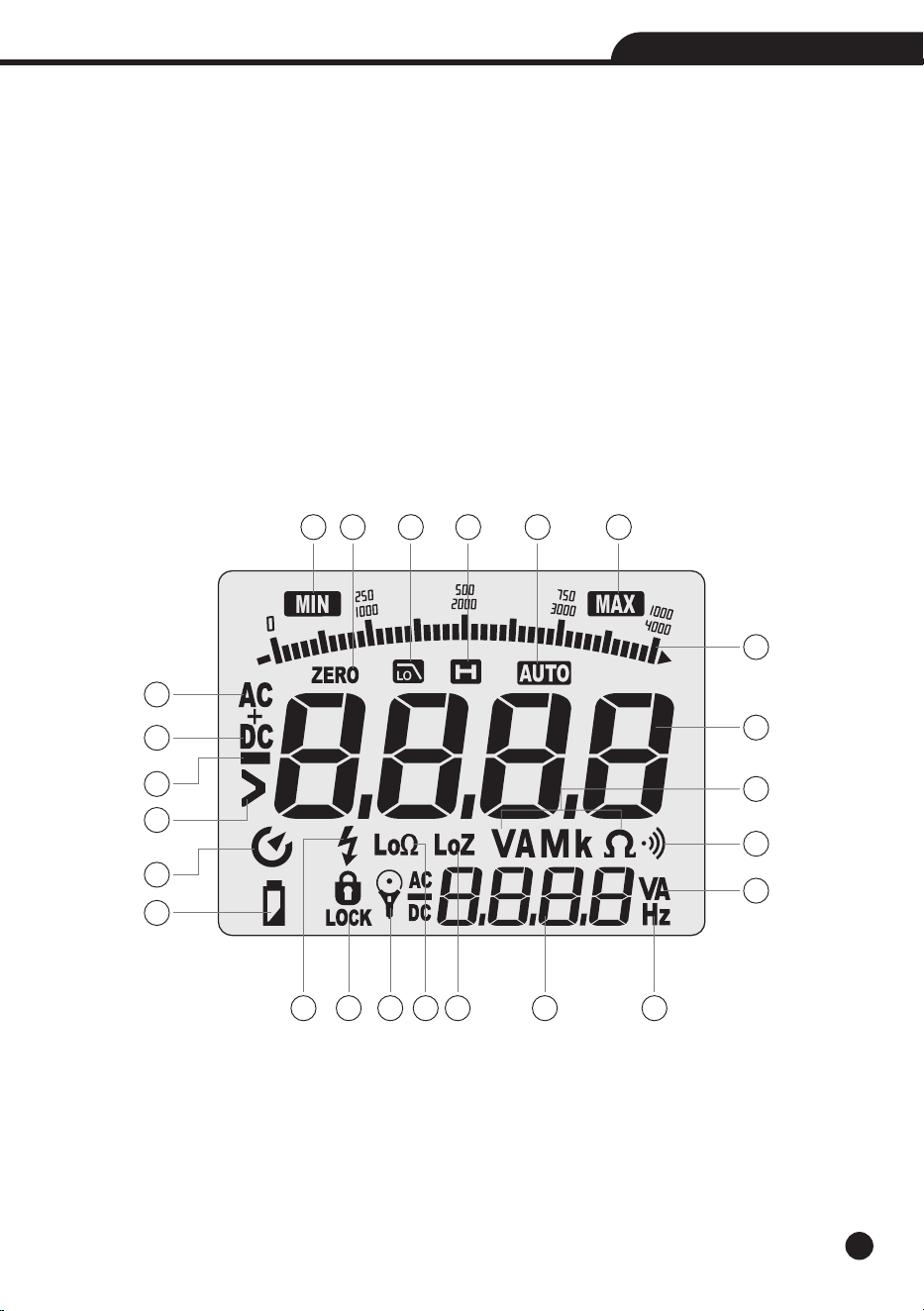
3-2.Description of the Display
1-Minimum Value
2-Zero Adjustment
3-Low Pass Filter
4-Data Hold
5-Auto Range
6-Maximum Value
7-Bar Graph
8-Main Display
9-Alternating Current
10-Direct Current
11-Minus Sign
12-Greater Than
1 62 3 4 5
7
9
10
11
12
13
14
8
15 16 17 1918
20
23
21
22
22
13-Auto Power Off
14-Low Battery
15-Test Voltage
16-Test Lock
17-Current Transducer
18-Low Impedance Test Mode
19-Low Input Impedance
20-Sub Display
21-Frequency
22-Units of Measure List
23-Audible Continuity

10
True RMS Multimeter & Insulation Tester
3-3.Button Function
3-3-1.RANGE Button
• Press the RANGE Button to activate the manual mode and to disable the Autorange function.
• The message “Manual” appears on the upper left part of the display instead of “AUTO”.
• In Manual mode, press the RANGE Button to change measuring range: The relevant decimal point will change
its position, the RANGE Button is not active in positions Lo , , INSULATION, Lo Z Voltage.Ω
• In Autorange mode, the instrument selects the most appropriate ratio for carrying out measurement.
• If a reading is higher than the maximum measurable value, the indication “O.L” appears on the display.
• Press and hold the RANGE Button for more than 1 second to exit the manual mode and restore the Autorange
mode.
• Press the RANGE Button to select “30A, 300A, 3000A”.
3-3-2.Backlight Button
• Press and hold the Backlight Button for more than one second to turn the backlight on or off.
• The backlight will automatically turns off after approximately 3 minutes.
3-3-3.MAX/MIN Button
• When the MAX/MIN Button is pressed, the meter keeps track of the minimum and maximum value of the
measurement for VAC, VDC, Continuity and Ohms.
• The first press of the MAX/MIN Button displays the MAX value, the second press displays the MIN value.
• To return to normal measuring mode, press and hold the MAX/MIN Button for more than one second.
3-3-4.MODE Button
• Momentarily press the MODE Button to select AC Voltage, LPF or Frequency , DC Voltage or AC+DC Voltage.
• The meter will automatically power OFF after 15 minutes of inactivity, to disable auto-power off, press and hold
the MODE Button while powering on.
• Press and hold the MODE Button to select the low-pass filter mode.
3-3-5.HOLD Button
• Press the HOLD Button to hold the measurement on the display.
• Press again to release the display to return to live measuring (not for insulation resistance testing).
3-3-6.TEST Button
• With the test leads connected to the equipment under test, press and hold the TEST Button to begin an insulation
resistance test.
• The lower-right display will show test voltage, and the main display will show the resistance.
3-3-7.LOCK Button
• For hands-free insulation resistance testing, use the LOCK Button feature.
• With the test leads connected to the equipment under test, press the LOCK Button for two seconds, and then
press the TEST Button to begin the test.
• The lock icon will appear on the display and the meter will beep to indicate it is in lock mode.
• Press the TEST Button to end the test.
11
True RMS Multimeter & Insulation Tester
4.Operating Instructions
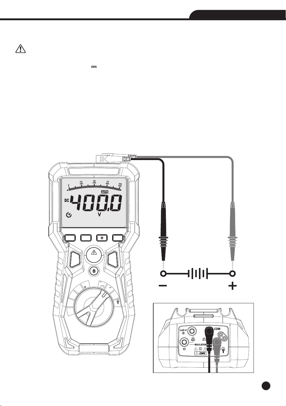
4-1.DC/AC+DC Voltage Measurement
CAUTION: The maximum input DC voltage is 1000V. Do not measure voltages exceeding the limits given in
this manual. Exceeding voltage limits could result in electrical shocks to the user and damage to the instrument.
1.Set the function switch to the V /AC+DC Position.
2.Insert the black test lead into the Input Terminal COM and the red test lead into the Input Terminal V/Hz/3000A
/INSULATION+.
3.Position the red lead and the black lead respectively in the spots with positive and negative potential of the circuit
to be measured .
4.The display shows the value of voltage.
5.If the display shows the message “O.L”, select a higher range.
6.For AC+DC measurement, press the MODE Button to indicate “AC+DC” on the display.
MODE HOLD
TEST
RANGE ZERO
MAX
MIN
OFF
V
Hz
LO
LoΩ
MΩ
125V
MΩ
250V
MΩ
500V
MΩ
1000V
V
Lo Z
3000A
V
AC+DC
Auto Power Off
True RMS Multimeter & Insulation Tester
12
True RMS Multimeter & Insulation Tester
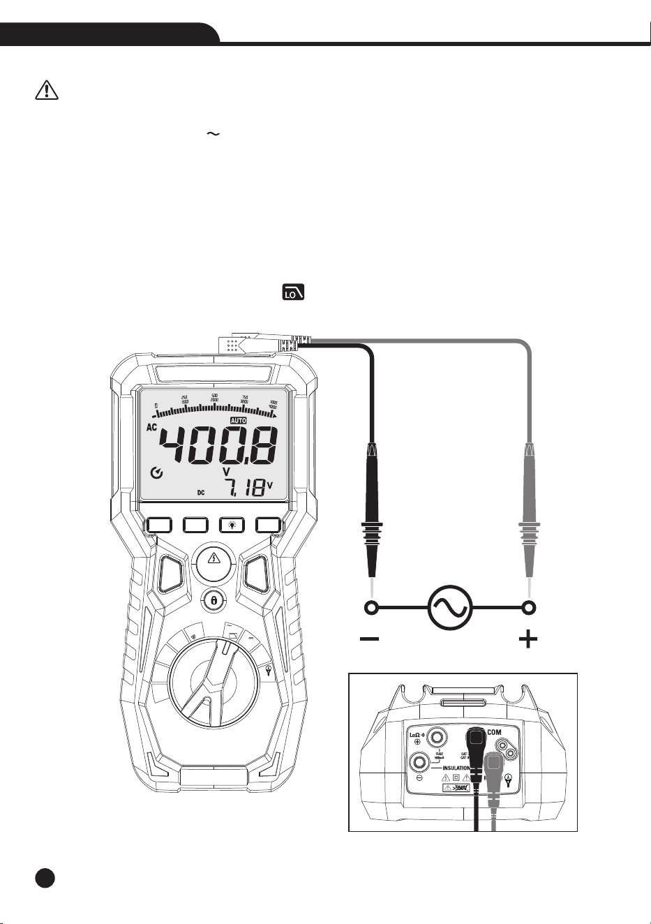
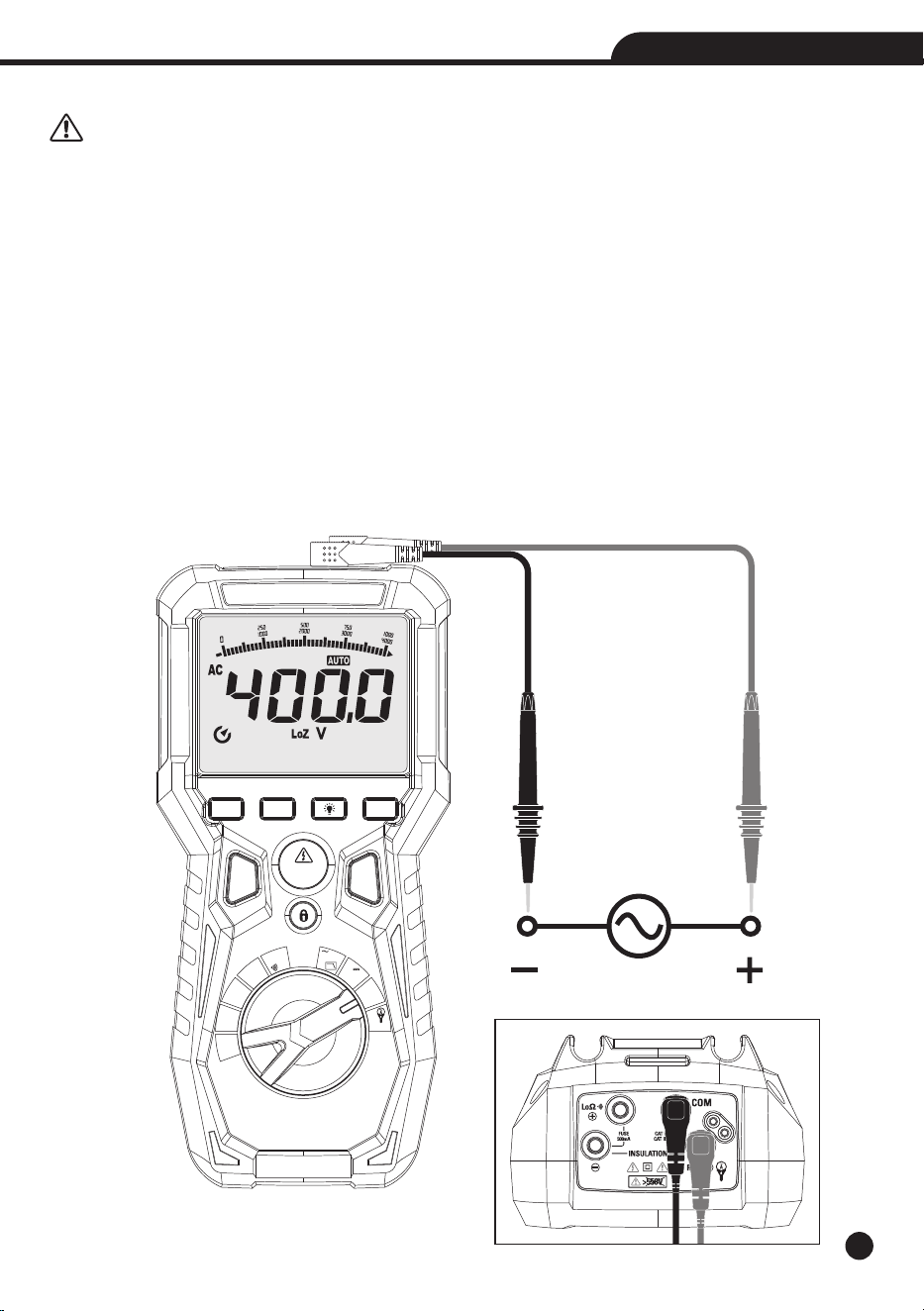
4-2.AC Voltage Measurement
CAUTION: The maximum input AC voltage is 1000V. Do not measure voltages exceeding the limits given in
this manual. Exceeding voltage limits could result in electrical shocks to the user and damage to the instrument.
1.Set the function switch to the V /Hz/LPF Position.
2.Insert the black test lead into the Input Terminal COM and the red test lead into the Input Terminal V/Hz/3000A
/INSULATION+.
3.Position the black test probe tip and red test probe tip respectively in the spots of the circuit to be measured.
4.Read the AC voltage in the display.
5.If the display shows the message “O.L”, select a higher range.
6.Press the MODE Button to select measurements “Hz” in order to display the values of frequency input voltage.
7. Press the MODE Button to select low pass filter test.
8. Press and hold the MODE Button to indicate “ ” on the display.
MODE HOLD
TEST
RANGE ZERO
MAX
MIN
OFF
V
Hz
LO
LoΩ
MΩ
125V
MΩ
250V
MΩ
500V
MΩ
1000V
V
Lo Z
3000A
V
AC+DC
Auto Power Off
True RMS Multimeter & Insulation Tester
True RMS Multimeter & Insulation Tester
4-3.Low Z AC/DC Voltage Measurement
CAUTION: Observe all safety precautions when working on live voltage. Do not connect to circuits that exceed
1000V when the meter is set to Low z. Do not use Low Z when testing circuits that could be harmed by this function’s
low input impedance. Let the meter stabilize 15 minutes after using Lo Z.
• Low Z is used to check for “ghost” voltage.
• Ghost voltages are present when non-powered wires are in close proximity to wires powered wires.
• Capacitive coupling between wires make it appear that non-powered wires are connected to a real source of
voltage.
• The Low Z setting places a load on the circuit, which greatly reduces the voltage reading when connected to
ghost voltage.
1.Set the function switch to the Low Z Position.
2.Insert the black test lead into the Input Terminal COM and the red test lead into the Input Terminal V/Hz/3000A
/INSULATION+.
3.Touch the test leads to the circuit under test.
4.If the display shows the message “O.L”, select a higher range.
13
MODE HOLD
TEST
RANGE ZERO
MAX
MIN
OFF
V
Hz
LO
LoΩ
MΩ
125V
MΩ
250V
MΩ
500V
MΩ
1000V
V
Lo Z
3000A
V
AC+DC
Auto Power Off
True RMS Multimeter & Insulation Tester
14
True RMS Multimeter & Insulation Tester
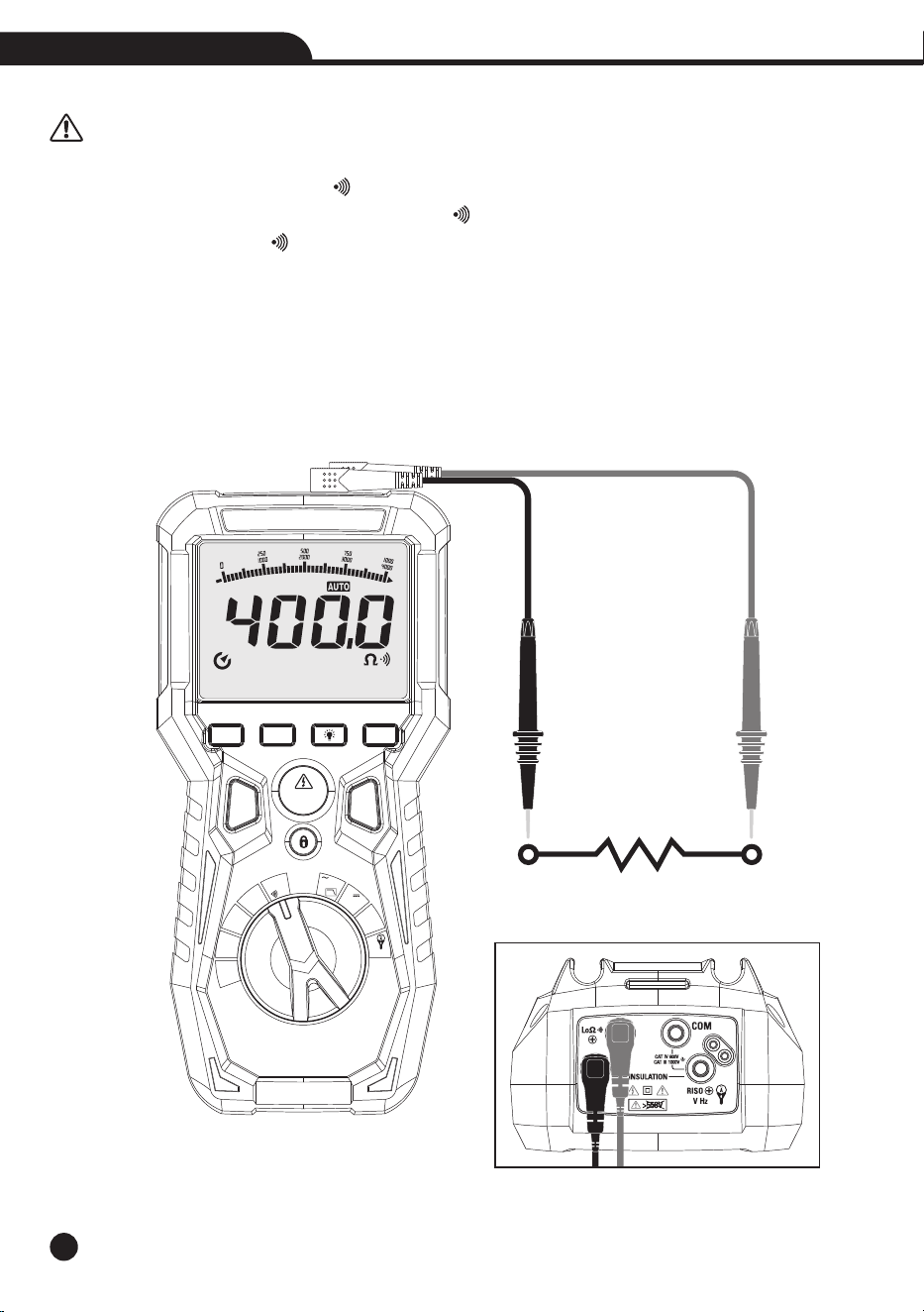
4-4.Resistance Measurement and Continuity Test
CAUTION: Before attempting any resistance measurement, cut off power supply from the circuit to be
measured and make sure that all capacitors are discharged, if present.
1.Set the function switch to the Lo / Position.Ω
2.Insert the black test lead into the Input Terminal / -/INSULATION- and the red test lead into the InputΩ
Terminal Input Terminal / +.Ω
3.Position the test leads in the desired spots of the circuit to be measured.
4.The display shows the value of resistance.
5.If the display shows the message “O.L”, select a higher range.
6.The value of resistance (which is only indicative) is displayed in and the instrument sounds if the value of
resistance is <30 .Ω
MODE HOLD
TEST
RANGE ZERO
MAX
MIN
OFF
V
Hz
LO
LoΩ
MΩ
125V
MΩ
250V
MΩ
500V
MΩ
1000V
V
Lo Z
3000A
V
AC+DC
Auto Power Off
True RMS Multimeter & Insulation Tester
15
True RMS Multimeter & Insulation Tester
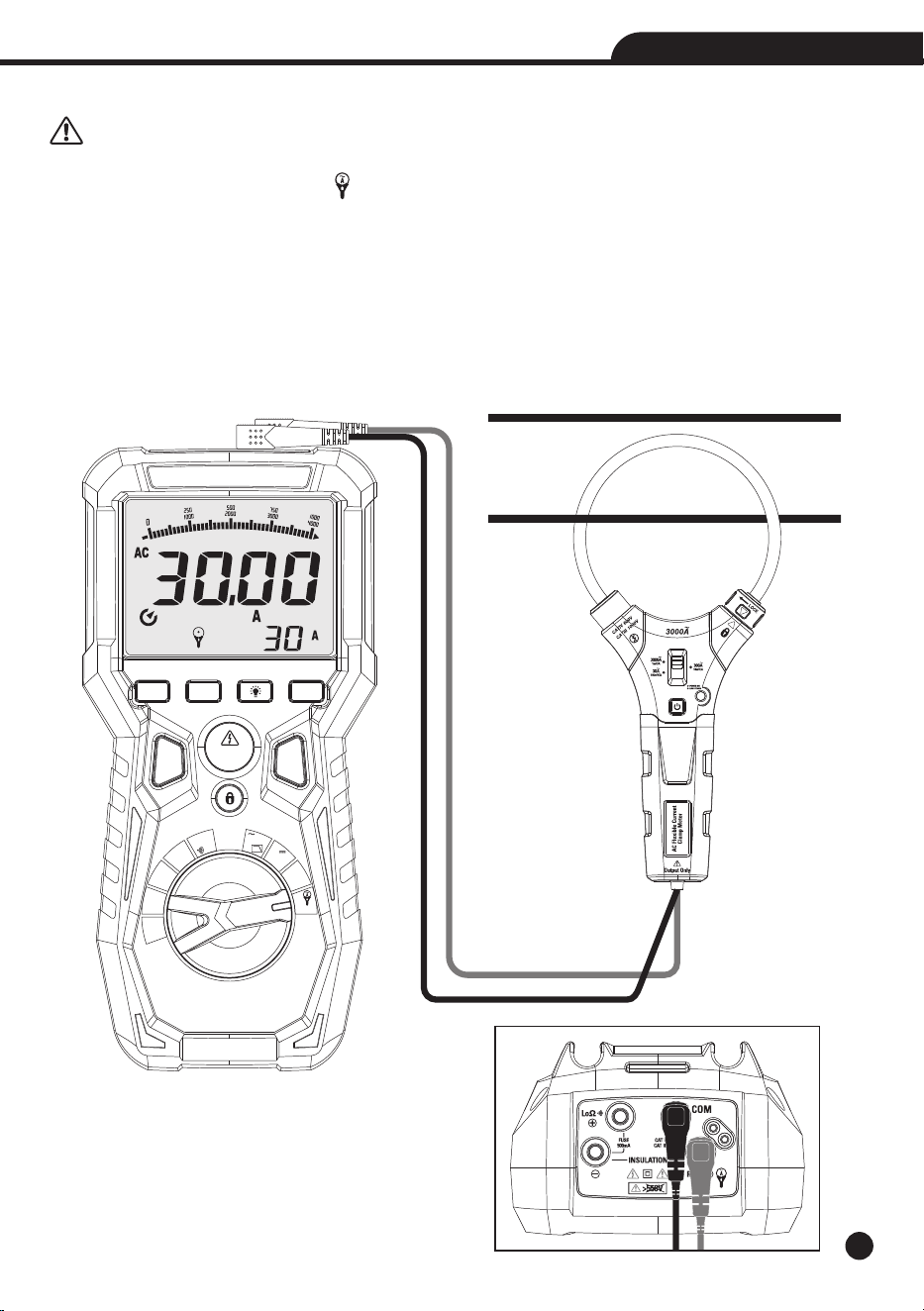
4-5.AC Current (with Current Transducer) Measurement
CAUTION: Maximum input AC current is 3000A (input VHz ). Do not measure currents exceeding the limits
given in this manual.
1.Set the function switch to the 3000A Position.
2.Insert the black test lead into the Input Terminal COM and the red test lead into the Input Terminal V/Hz/3000A
/INSULATION+.
3. Press the RANGE Button to select “30A 300A 3000A” AC urrent measurement. , , C
4.Select current Transducer Rang.
5.Press the lock catch to open jaw, fully enclose only one conductor, for optimum results, center the conductor in
the jaw.
6.The meter LCD will display the reading.
MODE HOLD
TEST
RANGE ZERO
MAX
MIN
OFF
V
Hz
LO
LoΩ
MΩ
125V
MΩ
250V
MΩ
500V
MΩ
1000V
V
Lo Z
3000A
V
AC+DC
Auto Power Off
True RMS Multimeter & Insulation Tester
16
True RMS Multimeter & Insulation Tester
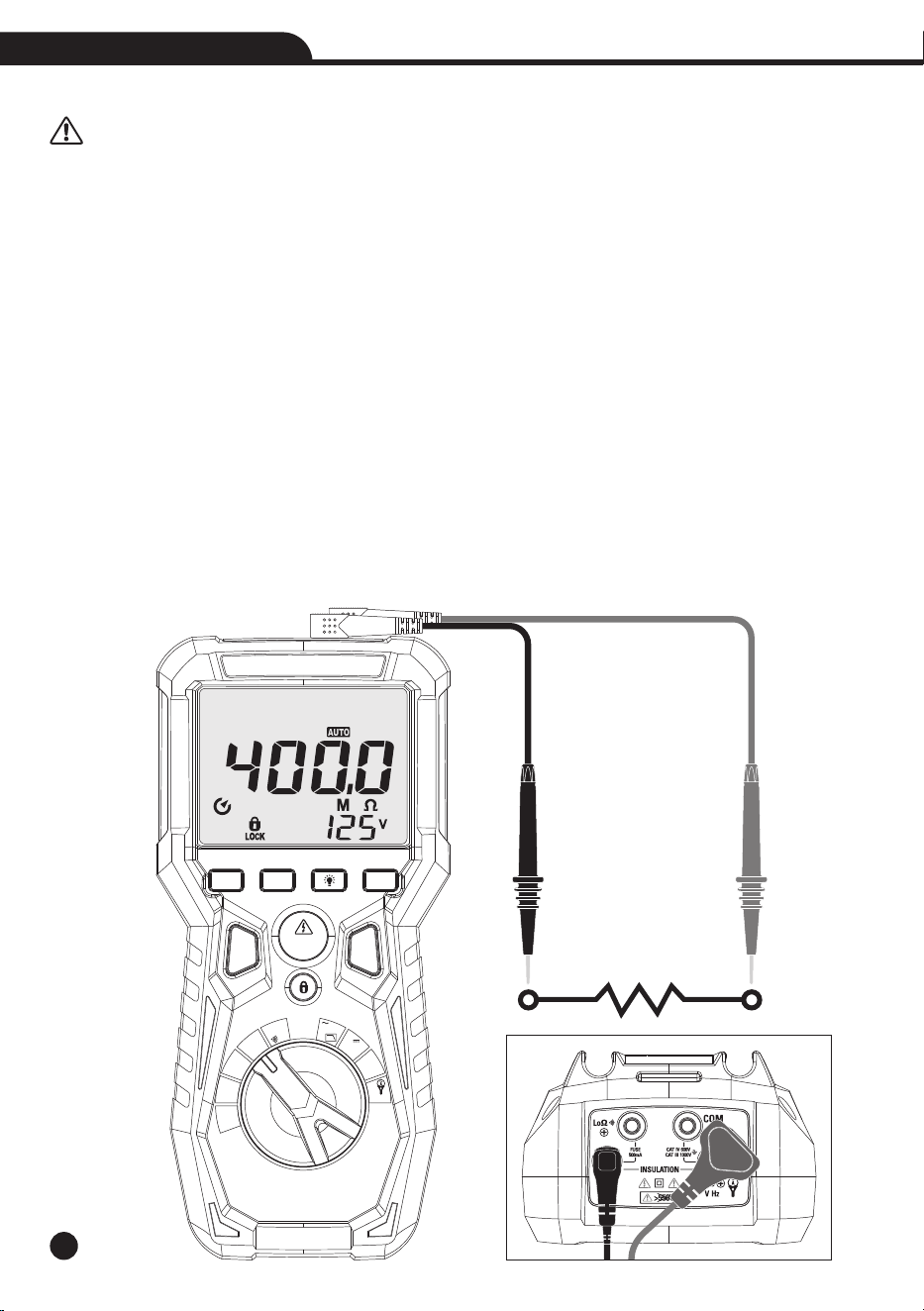
4-6.Insulation Resistance Measurement
CAUTION: Measurements can be adversely affected by impedances of additional operating circuits connected in parallel or
by transient currents.
1.Insert the red cable into Input Terminal INSULATION+, and the black cable into Input Terminal INSULATION-,
and rotate the function selector to the desired test voltage.
2.Choose from 125V, 250V, 500V or 1000V based on the compatibility with the device tested.
Note: Disconnect the circuit under test and isolate it from any stray resistance, Insulation test should only be
performed on de-energized circuits.
3.Connect the Red and Black cable to the circuit under test, if there is a voltage in the circuit, a constant beep will
sound and the Test Voltage symbol will be displayed, disconnect the circuit to proceed.
4.Press and hold the TEST Button to begin test, the lower right display shows test voltage, and the main display
shows the resistance.
5.The measured insulation resistance is displayed on the main display in M , allow the reading to stabilize beforeΩ
recording the measurement, turning the function switch, at any time during the insulation test will end the testing
process.
6.The circuit will discharge through the meter, keep the test leads connected until the circuit is completely
discharged and the lower right display shows near zero volts.
Note: Measurements can be adversely affected by impedances of additional operating circuits connected in parallel
or by transient currents.
Note: Overload “----” for insulation resistance measurements.
MODE HOLD
TEST
RANGE ZERO
MAX
MIN
OFF
V
Hz
LO
LoΩ
MΩ
125V
MΩ
250V
MΩ
500V
MΩ
1000V
V
Lo Z
3000A
V
AC+DC
Auto Power Off
True RMS Multimeter & Insulation Tester
17
True RMS Multimeter & Insulation Tester
5. Maintenance
CAUTION:
• Only expert and trained technicians should perform maintenance operations.
• Before carrying out maintenance operations, disconnect all cables from the input terminals.
• Do not use the instrument in environments with high humidity levels or high temperatures, do not expose to direct
sunlight.
• Always switch off the instrument after use.
• In case the instrument is not to be used for a long time, remove the battery to avoid liquid leaks that could damage
the instrument’s internal circuits.
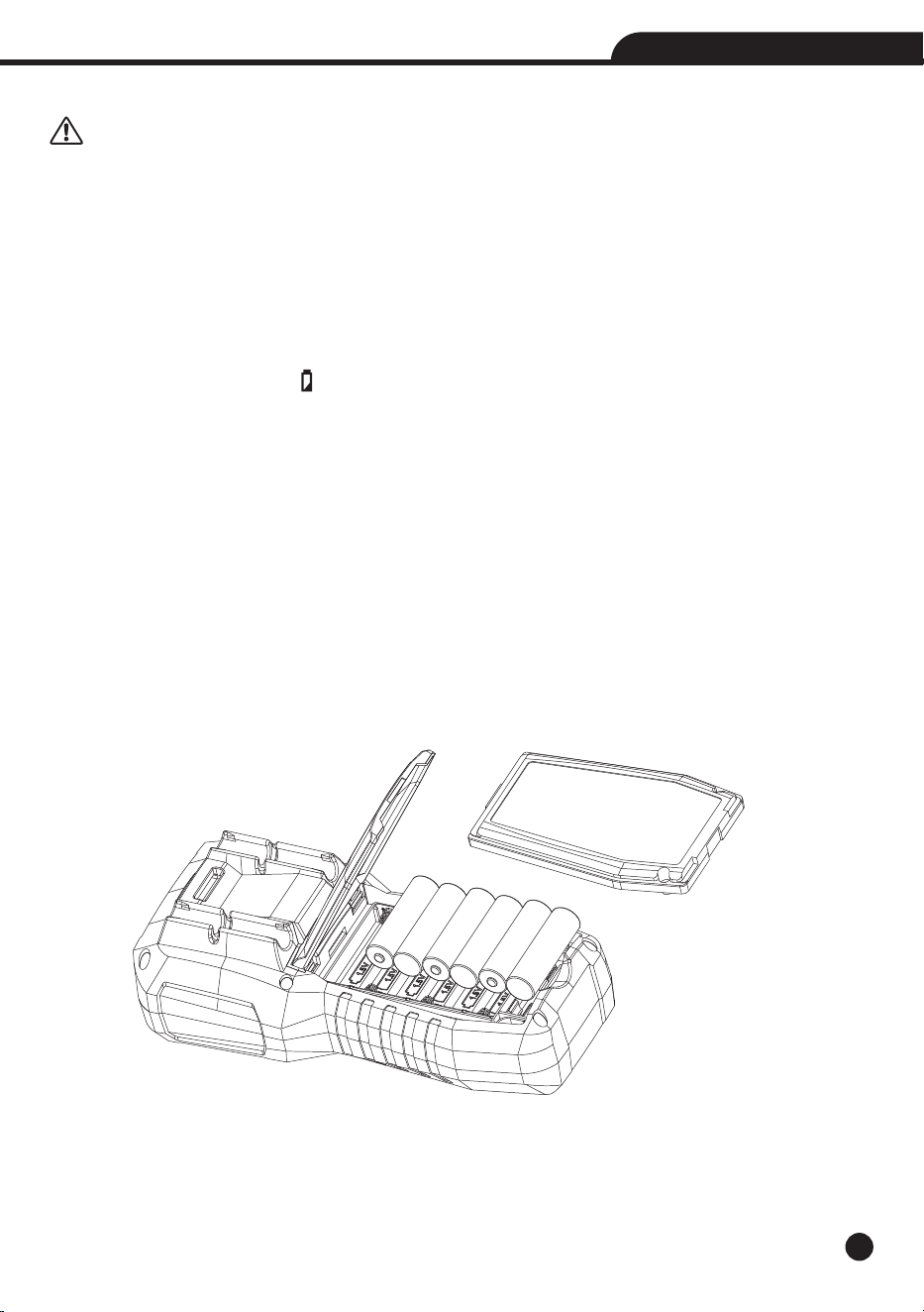
5-1. The Internal Battery
• When the LCD displays symbol “ ”, it is necessary to replace the batteries.
• Refer to Figure and replace the batteries as follows:
1.Turn the Meter off and remove the test leads from the terminals.
2.Remove the battery door assembly by using a standard blade screwdriver to turn the battery door screw one-half
turn counterclockwise.
3.Replace the batteries 1.5V AA x 6.
4.Reinstall the battery door assembly and secure it by turning the screw one-half turn clockwise.
WARNING: To avoid electric shock, disconnect the test leads from any source of voltage before removing the
battery cover.
WARNING: To avoid electric shock, do not operate the meter until the battery cover is in place and fastened
securely.
18
True RMS Multimeter & Insulation Tester
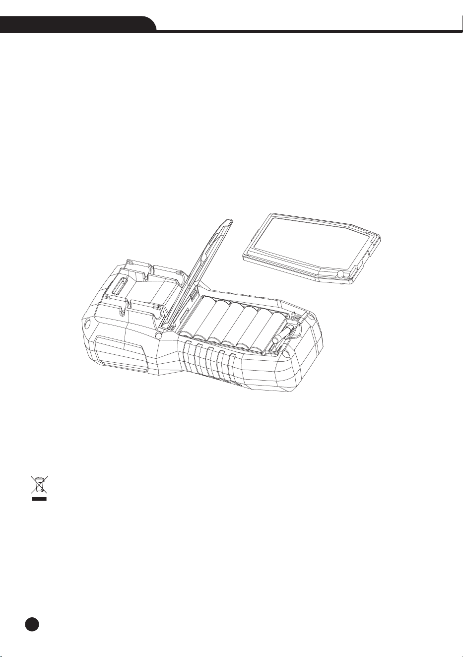
5-2.Replacement of Internal Fuses
Referring to Figure, examine or replace the Meter’s fuses as follows:
1.Turn the Meter off and remove the test leads from the terminals.
2.Remove the battery door assembly by using a standard blade screwdriver to turn the battery door screw one-half
turn counterclockwise.
3.Remove the fuse by gently prying one end loose, then sliding the fuse out of its bracket.
4.Install only specified replacement fuses.
5.Reinstall the battery door assembly and secure it by turning the screw one-half turn clockwise.
WARNING: To avoid electric shock, disconnect the test leads from any source of voltage before removing the
meter cover.
WARNING: To avoid electric shock, do not operate your meter until the fuse cover is in place and fastened securely.
5-3.Cleaning the Instrument
• Use a soft and dry cloth to clean the instrument.
• Never use wet cloths, solvents, water, etc.
5-4.End of Life
WARNING: the symbol on the instrument indicates that the appliance and its accessories must be
collected separately and correctly disposed of.
19
True RMS Multimeter & Insulation Tester
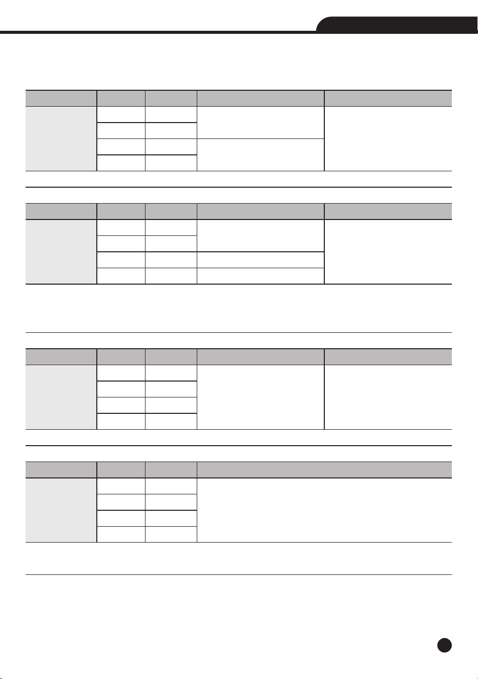
6.Specifications
6-1.Technical Specifications
Accuracy calculated as [%reading + (num. digits*resolution)] at 18 to 28°C; <75%HR.
Range
4.000V
40.00V
400.0V
1000V
Range
4.000V
40.00V
400.0V
1000V
Range
4.000V
40.00V
400.0V
1000V
Range
4.000V
40.00V
400.0V
1000V
Resolution
0.001V
0.01V
0.1V
1V
Resolution
0.001V
0.01V
0.1V
1V
Resolution
0.001V
0.01V
0.1V
1V
Resolution
1mV
10mV
0.1V
1V
Accuracy
±(0.5% + 5 digits)
±(1.0% + 5 digits)
Accuracy
*
(50 to 60Hz)
±(0.9% + 5 digits)
±(1.0% + 5 digits)
±(1.2% + 5 digits)
Accuracy (50 to 1kHz)
±(3.0% + 20 digits)
Accuracy
±(3.0% + 40 digits)
Ω
Input Impedance
>10M
Accuracy
*
(61 to 1kHz)
±(3.0% + 5 digits)
Input Impedance
>10M
Ω
Function
DC Voltage
Protection against overcharge: 1000VDC/ACrms
Function
AC TRMS Voltage
Protection against overcharge 1000VDC/ACrms.
( )Accuracy specified from 10% to 100% of the measuring range, Input impedance: >9M .
*
Ω
Distorted, pulsed, triangle or trapezia waveform Accuracy: (10%rdg + 10dgt).
Function
AC+DC TRMS
Voltage
Protection against overcharge: 1000VDC/ACrms
Function
AC/DC Voltage
(Low Z)
Protection against overcharge: 1000VDC/ACrms
Input Impedance: Approx. ~3kΩ
20
True RMS Multimeter & Insulation Tester
Accuracy
*
(50 to 1kHz)
±(1.2% + 10 digits)
Buzzer
<40
Range
30A*
300A*
3000A*
Range
40.0
400.0
Range
40.00Hz to 1kHz
Transducer Ratio
100mV/1A
10mV/1A
1mV/1A
Resolution
0.1
0.1
Resolution
0.01A
0.1A
10A
Accuracy
±(0.5% + 3 digits)
±(2.5% + 8 digits)
Ω
Ω
Ω
Ω
Ω
Resolution
0.01Hz to 1Hz
Accuracy
±(0.5%reading)
Function
AC Current
(with Current
Transducer)
Protection against overcharge: 1000VDC/ACrms
( ) Accuracy specified from 5% to 100% of the measuring range
*
( ) Do not include the accuracy of current Transducer
*
with Current Transducer (30A*/300A*/3000* Rang Corresponding Current Transducer Range)
*
Distorted, Pulsed, Triangle or Trapezia waveform Accuracy: (10%rdg + 10dgt)
Function
Resistance and
Continuity Test
Protection against overcharge: 300VDC/ACrms
Continuity Beeper: Audible signal when resistance <40Ω.
Short circuit >200mA; Open circuit voltage 5.5V DC.
Function
Frequency
(Electronic)
Protection against overcharge: 1000VDC/ACrms
Sensitivity: 2Vrms
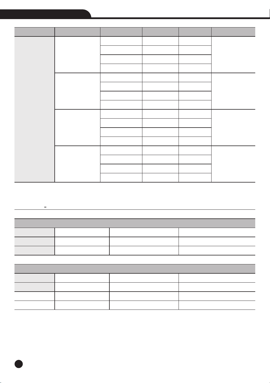
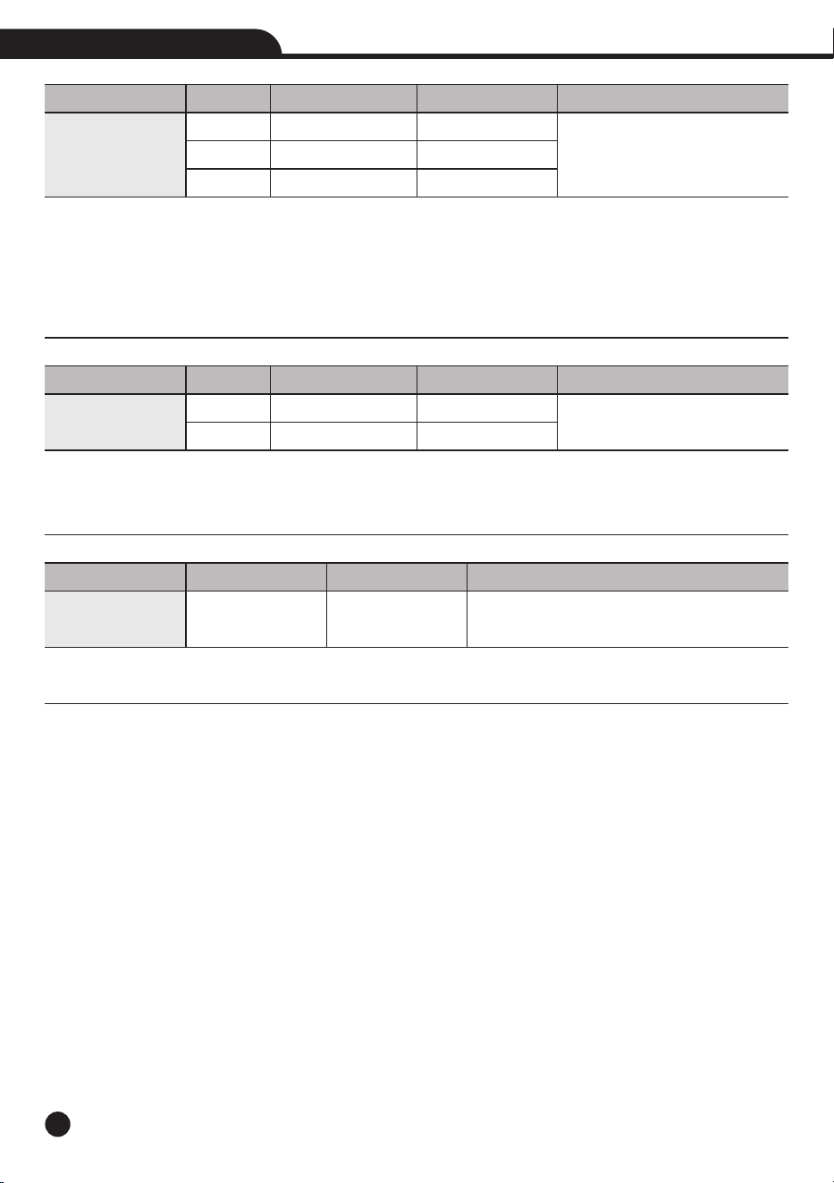
21
True RMS Multimeter & Insulation Tester
Terminal Voltage
125V (0%~20%)
250V (0%~20%)
500V (0%~20%)
1000V (0%~20%)
Measurement Intrinsic
Insulation Resistance
Earth-Bond Resistance
Variable
Position
Supply Voltage
Temperature
Range
0.125 to 4.000M
4.00 to 40.00M
40.0 to 400.0M
400 to 4000M
0.250 to 4.000M
4.000 to 40.00M
40.00 to 400.0M
400.0 to 4000M
0.500 to 4.000M
4.000 to 40.00M
40.00 to 400.0M
400.0 to 4000M
1.000 to 4.000M
4.000 to 40.00M
40.00 to 400.0M
400.0 to 4000M
Resolution
0.001M
0.01M
0.1M
1M
0.001M
0.01M
0.1M
1M
0.001M
0.01M
0.1M
1M
0.001M
0.01M
0.1M
1M
Ω
Ω
Ω
Ω
Ω
Ω
Ω
Ω
Ω
Ω
Ω
Ω
Ω
Ω
Ω
Ω
Ω
Ω
Ω
Ω
Ω
Ω
Ω
Ω
Ω
Ω
Ω
Ω
Ω
Ω
Accuracy
± (2.5%+10)
± (2%+10)
± (4%+5)
± (5%+5)
± (2%+15)
± (2%+10)
± (3%+5)
± (4%+5)
± (2%+10)
± (2%+10)
± (2%+5)
± (4%+5)
± (3%+10)
± (2%+10)
± (2%+5)
± (4%+5)
Test Current
1mA at load 125k
1mA at load 250k
1mA at load 500k
1mA at load 1M
Ω
Ω
Ω
Ω
Ω
Ω
Operating Uncertainty
See Electrical Specifications
See Electrical Specifications
Range
± 90°
7.21 to 9.13V
0 to 35°C
Maximum Uncertainty*
<30%
<30%
% Within Range
<5%
<5%
<5%
Function
Insulation
Resistances
Short Circuit <5mA.
Due to the alkaline battery charge, multiple tests so that the 1000 volt voltage through the 1M resistor,Ω
generally maintain the test time of about 5 seconds.
Intrinsic Uncertainity (EN61557)
Code
A
A
Influence Variables and Uncertainties (EN61557)
Code
E1
E2
E3

6-2.General Specifications
Safety
Safety
Insulation
Pollution Level
Overvoltage Category
Max Operating Altitude
Mechanical Characteristics
Size (L x W x H)
Weight (Batteries included)
Power Supply
Battery Type
Low Battery Indication
Auto Power Off
Fuses
Display
Conversion
Characteristics
Sampling Frequency
Environmental Conditions for Use
Reference Temperature
Operating Temperature
Allowable Relative Humidity
Storage Temperature
Storage Humidity
7.Accessories Provided
• Pair of Test Leads
• 6x1.5V AA Akline Batteries
• Carrying Bag
• User Manual
IEC EN 61010-1, 61010-2-030, 61010-2-033, 61326-1, 61557-1-2-4.
Double Insulation
2
CAT IV 600V, CAT III 1000V
2000m (6562ft)
175 x 85 x 55mm (7 x 3 x 2in)
800g
6x1.5V AA batteries, 1200mAh
symbol “ ” on the display
after 15 minutes’ idling (can be disabled)
F500mA/1000V, 6 x 32mm
TRMS
LCD, 4000 dots, decimal sign, point backlight and bargraph
3 times/s
18 to 28°C (64 to 82°F)
5 to 40°C (41 to 104°F)
<80 %RH
-20 to 60°C (-4 to 140°F)
<80 %RH
22
True RMS Multimeter & Insulation Tester