
1
POE300 PoE Tester and Monitor
How to use the PoE Tester / Power Monitor
PoE system: A PoE system comprises a PSE (Power Source Equipment) and
PD (Powered Device) two ports.
PSE: PoE switch, PoE midspan switch, PoE (active / Passive) injector.
PD: IP camera, IP phone and wireless AP and other network appliances.
PSE: Only provides power supply to PoE enabled devices.
Standard: IEEE 802.3 af (PoE), 802.3 at (PoE+), 802.3 bt (PoE++), 802.3 at delivers
30W or more power and backward compatible with 802.3 af.
(A) Standards based (802.3 af/at/bt) active PoE power is negotiated, only transmit
power when it detects the connection of PoE – enabled device, this can avoid the
risk of leakage and protects NON-PoE devices.
(B) Non-standards-based-passive PoE-power is always on, like passive injector which
will fry/damage a non-standard PD/equipment you’re about to connect.
Need to be aware of what kind of PoE you have and what it will work to avoid
damage the equipment.
Endspan (A) – display the voltage on pairs (+) 1/2 and (-) 3/6.
Midspan (B) – display the voltage on pairs (+) 4/5 and (-) 7/8.
● The tester is battery free operation.
● Designed for testing standard active and passive PoEs & Non-standard passive
PoEs.
● The tester can turn on the activity LED on PSE.
● Power (Watts) which is voltage multiplied by current.
● Mode A and Mode B can operate at the same time.
● If both A and B are powered, add the A and B values together.
● The tester can be used for Non-Standard/Passive PoE, which operate at
between 11V – 60V for detecting and verifying PSE is either standard/active
PoE or Non-standard/passive PoE with polarity and available voltage
monitoring and in-line testing.
Interface:
● PSE connector: For connecting PSE.
● PD connector: For connecting PD.
● PoE is subject to the same distance limitations as standard network cable runs –
100 meters (328 feet).

2
● PoE injector are Mid-span devices commonly deployed between a non-PoE
capable switch and a PoE-enabled PD.
Any of these can cause a problem
● Incompatibility between PSE and PD.
● Power limited per port.
● Switch provisioning of PoE.
● Didn’t turn PoE on port.
● Cable faults.
● Legacy devices.
● Equipment failure.
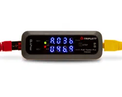
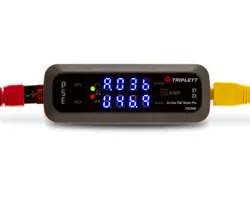
Display:
○
1
4 LEDs (Green + Red) display either IEEE 802.3 af or 802.3 at compliant
standard and either Endspan or Midspan or Ultra 4-pair power source.
One Green lit indicates 802.3 af – power source End (A).
Two Green lit indicates 802.3 at – power source End (A).
One Red lit indicates 802.3 af – power source Mid (B).
Two Red lit indicates 802.3 at – power source Mid (B).
Two Green + two Red lit indicates 802.3 at – Ultra 4-pair or 802.3 bt.
Note: The tester displays 802.3at with 4-pair ( End + Mid ) power source
instead of 802.3bt present.
○
2
2 Yellow LEDs indicates reversed polarity power source either Endspan
or Midspan or both.
○
3
Dual 4 digit LEDs, display voltage, current and power for both Endspan
and Midspan. Display in rotation between voltage, current andpower
U indicates voltage (Volts) P= V X I
A indicates current (mAs) p= Power. V=Voltage. I= Current.
P indicates power (Watts) I=V/R V-PSE voltage, R-PD Resistance
Display cycle : Voltage Ò Current Ò Power
○
4
Step button : For selecting specific test data for easier reading and
voltage display by default.
Operation Notices:
○
1
Performing inline testing in T-Mode should first connect the PSE side to the
tester, until voltage displayed then connect PD side.
○
2
The length of the cable and the quality of the cable or the pin location in the
RJ45 connector can affect the real power available to ensure the power at the
other
end of the wall outlet is what’s per PD required. So should test for the wattage
level at the wall outlet/jack where the PD plug in.
○
3
Step button allows you to select specific test data for easier reading

3
○
a
Press button once will change auto-rotate to step mode, and voltage display
by default, press button again to select current or power display.
○
b
Revert back to auto-rotate, just disconnecting the PSE side cable (If onin-line
testing disconnect PD side cable first, next disconnect PSE side cable), then
reconnecting the PSE to the tester. It will start auto-rotate display.
○
c
In case it not displayed in order. To perform a reset as below.
* First unplug the cable from PD side, next unplug the PSE side cable.
* Then reconnecting the PSE side until voltage values displayed then connect
the PD to be tested.
4. The tester cannot measure and test PD alone, it has to connect a PSE first,
then connect to the PD, after negotiation process each other, then start power
level testing. Note: Before connect PD to the tester. you have to make sure that
the PD to be connected is either a standard PoE powered device or a non-PoE
powered device to avoid a non-PoE device is damaged by a non-standard passive
PoE power.
TEST MODE SELECTOR which is on the back of the tester and is used to select the
test to be run. It includes T-Mode, N-Mode and I-Mode to simulate and monitor
PoE system operation.
A. T-Mode built-in PD controller simulate as PD, this will activate PSE power and
detect PSE status to identify the PoE presence on an Ethernet wall outlet and
proper voltage power for PoE application, and verify the PSE is delivering voltage
power compliant with standard alternative End[A] or Mid{B} or both [4-pair] and
with REV LEDs indicates a reversed power in Ethernet 802.3 af, 802.3at or 802.3bt
{type3 & 4} compliant standard. The tester displays 802.3at with 4-pair power
source indicates of 802.3bt present. Meanwhile it allows you to connect an PD to
perform an in-line testing to measure and display voltage available, current flowing
and how much power an PD actually need/consume ensure a sufficient power for
PD.
B. N-Mode is used for measuring, testing and determining Non-standard passive
PoE of power supply status and perform in-line testing as well as discriminate
802.3af is either a standard active PoE or a Non-standard passive PoE to avoid
damage to a non-PoE device, it also detects the circuits polarity of PoE. Voltage
range 11V to 60V. Once in T-Mode testing, there is displayed 802.3af of PoE or
no any display appear, then you have to set the tester to N-Mode for verifying
current 803.3af is either a standard active PoE or a Non-standard passive PoE.
1. If there is no any display appear this indicates that is a standard active 802.3af

4
PSE testing
PoE or a non-standard PoE less than 11V is measured.
2. If there is displayed voltage levels or come with REV polarity, this indicates that the
802.3af is a passive PoE and power is always on.
C. I-Mode In I-Mode the tester isolates the PD controller allows you to monitor and
troubleshoot real PoE system operation and learning exactly how much a PoE
device is drawing. It’s a simple and effective solution when troubleshooting
active and passive PoE connection. The tester monitors the current PSE power
supply status and display Volts, Amps and Watts or come with REV polarity LED
when connected to both an 802.3 af, at/bt PSE and PD to show if the PoE system
is functioning correctly. The display is inactive when no powered device is
connected, only if a standard passive switch/injector is connected, the voltage
levels will appear. PSE runs a discovery process which look for device that comply
with the PoE specification before applying power over the line. I-Mode will help
verify PoE system proper operation.
PSE TEST RESULT CHART
I-Mod
T-Mode
N-Mode
Standard Active af/at/bt PoE[48V-57V]
N
Y
N
Standard Passive af PoE[48V-57V]
Y
Y
Y
Non-Standard Passive PoE[11v-57V]
N
N
Y
Y: Display Voltage N: Non Displayed
Warring:
1. Never connect a reversed or unprotected PSE to PD test port, this can cause
damage to a reversed and unprotected PoE switch, injector and equipment or
tester.
2. Once the tester displays “ HI “ which indicates the power over 60V, must be
removed the cable from the tester immediately, avoiding damage to the
tester from high voltage.
Operation:
A. –In T-Mode and N-Mode
Monitor activity PoE by connecting at the PSE or outlet to check PSE or Ethernet
outlet for PoE power and identify its standard (af/at), power source (End or Mid
or both), polarity and measures and displays PSE voltage values. Let you know
how much power is going to each cable run, you don’t have to guess at the port
you need to use. Put it in-line and you can see exactly what the voltage, current
and power values, ensuring that your PoE device have the proper power.
It checks the existence of PoE system in one second.

5
Ensure the power at the other end of the cable or wall outlet is what’s per PD
required. So should test for the voltage and power level at the wall outlet where
the PD plug in.
1. Connected PSE jack of the tester with a cat 5 above patch cable to either an rj45
Ethernet outlet or a PoE switch or injector port.
2. The display will be activated, includes standard type, power source, polarity
and voltage values.
3. Check the LEDs indicators on the front panel for PoE standard type either 802.3 af
or 802.3 at, and power source either Endspan (A) or Midspan (B) and whether
it is over 2 pairs or 4 pairs as an 802.3 bt or Ultra-4 pairs and whether the power
source is reversed polarity.
4. Read the voltage values to confirm proper power draw for PD.
5. If both A and B mode display activate, the power will be the total of the two
displayed values. This indicates that PSE is 802.3 bt/U PoE.
6. The tester will be detected the 802.3 bt which activate both End and Midpower
source as 802.3 at instead.
NOTE: 1. Most of market PoE injectors are belong to passive injector which power
is always on, problems often occur to damage a passive switch/injector PoE
end devices. Need to be aware of what kind of PSE either standard active
or passive PoE you have. Once the tester displays PoE type as
802.3 af which may not be an active injector but it may be a
passive injector/switch. For safety, please double check with in N-
Mode.
To make sure that it is a standard active PoE injector or a Non-standard
passive injector.
If there is no any display appears in N-Mode this indicates that is standard
active PoE.
If there is voltage displayed, this indicates that is a Non-standard passive
PoE and the power is always on.
2. In T-Mode or N-Mode once the voltage levels displayed it means that PSEis
outputting power on the PD connector of the tester, before connect a
powered device to the PD test port of the tester you have to know and
make sure the PD either a PoE enabled device or a non-PoE device and
know what PoE voltage your device requires before plugging in the PD
test port to avoid a non-PoE device is damaged by the live circuits, or if you
connect the wrong voltage you may cause permanent damage the device.

6
B.
Performs in T-Mode, N-Mode and I Mode.
PE-200BTN is made specifically for testing, monitoring and troubleshooting
PoE system. Increased productivity and efficiency. Testing includes voltage and
inline current measurement to determine the actual power consumed by a PD.
It’s built-in a Gigabit Ethernet transformer for PoE++ application to isolate data
passes and measure power without interruption of data.
In-line testing – Measure actual power used by PD, with loaded power, voltage,
current, standard type of PoE, power source mode and power
polarity. It provides the power consumption status in real time
and confirms your PoE network system for just all the power you
do need.
The test must be connected in between the PSE and PD.
It shows the voltage provide by the PSE and the power values
are following to PD to ensure sufficient power for PD actually
need.
○
1
In T-Mode connected PSE jack of the tester with a Cat 5 or above patch cable
to a PSE port or Ethernet PoE outlet first, the tester auto trigger PSE to turn on
and display the voltage values, then connected PD jack to a PD.
Note: Before connect a PD to the tester, you have to make sure that the PD to
be connected is either a PoE-enabled device or a non-PoE device, to
avoid a non-PoE device is damaged by a non-standard passive PoE
power.
○
2
Once a PoE-enabled device (PD) is connected, after negotiating each other
and activate then the power is following to the PD, the tester will start to show
in rotation between voltage, current and power (Watts).
○
3
PSE may provide power on all 4 pairs like 802.3 bt (PoE++) /UPoE, both
Endspan and Midspan displays will activate, add the two displayed values for
the power.
○
4
For easier reading the test data, by pressing the step button to select
the specific data. Voltage display by default.
○
5
This confirms proper voltage power provided by the PSE and ensure the
power required by PD in 802.3 af, at or bt standard.
To avoid problems, when working on existing PoE system networks, always use the
tester to check for wire connection to see if either PoE, or PoE+ or PoE++ is present,
and how much voltage power is provided by the PSE, these information can help you
to get a right PD and no more damage by live circuits.
In-line Testing

7
C.
( I ) A PD (powered device) will not power up and the LED on the switch isn’t on.
Step 1 — Make sure the PD is a standard device based on IEEE 802.3 af or at.
Ensure the right Cat 5 or above cable and plug into the right port on
the PD.
The length of the cable cannot over 100m.
Confirm power supply mode End or Mid and polarity.
Step 2 — If power is not detected from the PSE, check the switch
configuration to verify the PoE setting each interface until the LED
light on the switch, the PoE power is being supplied.
Step 3
— Verifies PSE or injector the powering method, either standard or
Non-standard or passive or 802.3 af/at is compatible with the PD.
Passive injector is a non-standard PoE and is not compatible with
af/at standard.
Step 4 — Connect tester inline between PSE and PD to troubleshoot PoE link
configuration issues. The tester will verify the PoE power pairs, PoE
standard type, power polarity, line voltage and measure the actual
current provide to the PD.
In T-Mode once PoE is activated, the tester displays if either 802.3 af or at standard is
present, and power source End or Mid or both, polarity and display the voltage
under current load.
NOTE: Cable dissipation (Voltage drop), over a 100m (328ft) length, Cat 5 or higher
(12.5Ω) resistance. Would be 4.12VDC in an 802.3 af type 1 installation.
Would be 7VDC in an 802.3 at type 2 installation.
S Packaging includes:
○
1
PE-200BTN
○
2
White or color box.
○
3
User Manual.
○
4
Pouch (optional).
PoE – Troubleshooting

8
Reference Data
Property
802.3 af
(PoE)
Type 1
802.3 at
(PoE+)
Type 2
802.3 bt
(PoE++)
Type 3
802.3 bt
(PoE++)
Type 4
UPoE
NON-Standar
d
Max power
delivered by
PSE (Watts)
15.4
30
60
90/100
60
Minimum
power
Available for
PD (Watts)
12.95
25.5
51-60
71-90
51
Voltage range
At PSE (Volts)
44-57
50-57
50-57
52-57
Max57
Provide voltage
Available at PD
(Volts)
37-57
42.5-57
42.5-57
41.1-57
Max57
Max current
(mA)
350
600
600/per
mode
960/per
mode
600-720
Used number
of
energized pairs
2 pairs
2 pairs
4 pairs
4 pairs
4 pairs
Classification Table
Class Number
PSE output
Power (W)
PD input
power (W)
PD type
Notes
0
15.4
12.95
1
IEEE802.3 af
(2-pair PoE)
1
4
3.84
1
2
7
6.49
1
3
15.4
12.95
1
4
30
25.5
2
IEEE 802.3 at
(PoE+)
5
45
40
3
IEEE802.3 bt
(4-pair PoE,
4PPoE, PoE++)
6
60
51
3
7
75
62
4
IEEE 802.3 bt
(higher-power
PoE)
8
90
73
4

9
Note:
○
1
The PoE power source do not always meet the wattage specification for
their class.
○
2
Actual wattage can Vary and it depends on the length of cabling and
cable type.
Specification POE3000
Connector
Interface
2X RJ45 jack (PSE test jack, PD test jack)
Support of testing
Standard active/passive PoE af,at & bt
NON-standard passive PoE 11V to 60V
PoE-PoH (power over HDBaseT)
UPoE (Universal power over Ethernet)
Main Functions
* Detects PSE-type/class, power source, polarity and voltage
* Determines-standard PoE or NON-standard passive PoE
* Inline power level monitoring
Voltage range
Standard PoE 36V to 60V
For both mode A & mode B
NON-standard PoE 11V to 60V
Max Current
(based on 50V)
990mA/50W per mode total 2 Amp/100W
Gigabit (PoE++)
Ethernet
Transformer
Support 10/100 AND Gigabit data rates. To isolate data passes
through for all 4 pairs and measure power without interruption of
data.
Function
Selection Mode
T mode: for detecting PSE status
N mode: for determining NON-standard PoE + inline testing
I mode: for testing and monitoring real time power status
Display
* 4 LEDs indicate IEEE 802.3 af or 802.3 at/bt standard.
* Dual 7-digit LEDs indicate power source either End (A)
Span (1/2,3/6) or Mid (B) span (4/5,7/8) or both for bt.
* 2 Yellow LEDs indicate reversed polarity for power type.
* Display in rotation between voltage (U) (Vots), current
(A) (mAs ) and power (P) (Watts).
Standard
compliant
IEEE 802.3 af (PoE), 802.3 at (PoE+), and 802.3bt (PoE++) type3 &
type4 standard.
Step Button
For selecting specific data to display.
Default display for voltage value.
Operating Temp.
Storage Temp.
32°F to 122°F (0°C to 50°C).
-40°F to 131°F (-20°C to 55°C).
Operating
Humidity
MAX 90% non – condensing.
Size
99 X 36 X 26mm / 3.9 X 1.4 X 1 inch. 0.1lb / 1.6oz.
Certification and
compliance
CE, FCC, RoHS.
10