Please read this manual before switching the unit on.
Important safety information inside.
LV
LVPRO40
10Gb Multifunctional Low Voltage Cable/Network Tester


3
Cable/Network Tester
Page
4
4
5
6
6
8
10
10
11
11
11
12
12
12
13
13
13
13
13
14
14
15
15
15
15
16
16
17
18
18
Content
1.Introduction.............................................................................................
2.Safety......................................................................................................
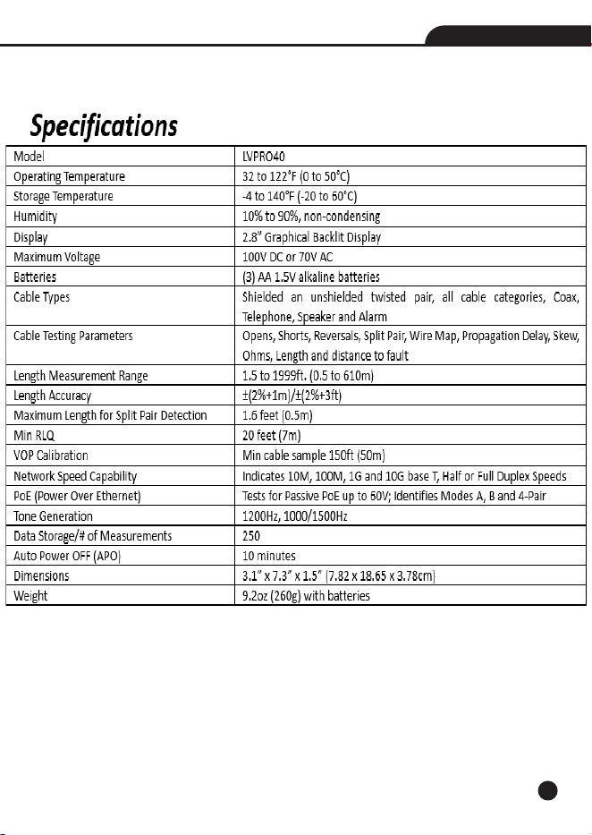
3.General Specifications..............................................................................
4.Description..............................................................................................
4-1.Meter Description...............................................................................
4-2.Symbols Used on LCD Display..............................................................
5.Operation.................................................................................................
5-1.Length Test.........................................................................................
5-2.Cable Test...........................................................................................
5-3.RLQ Test.............................................................................................
5-4.Phone Devices Test.............................................................................
5-5.Video Devices Test..............................................................................
5-6.Speaker/Alarm Devices Test................................................................
5-6-1.Speaker Popper.............................................................................
5-6-2.Alarm Battery Test.........................................................................
5-7.Network Device Testing.....................................................................
5-7-1.Port Blink Cable Detection.............................................................
5-7-2.10/100/1000 Detection/Advertised Speed/Pairs Used......................
5-7-3.Power Over Ethernet/Pairs Used.....................................................
5-8.Tone Cable Detection..........................................................................
5-9.Wall Jack Identifiers...........................................................................
6.Wiring and Display Examples....................................................................
6-1.T568B Data Cable Properly Wired.........................................................
6-2.T568B Cross Over Data Cable Properly Wired........................................
6-3.T568B Data Cable with a Shorted And Open Pair...................................
6-4.T568B Data Cable with Split pairs........................................................
6-5.T568B Data Cable with Reversed Pair and Crossed Connection..............
7.Data Export..............................................................................................
8.Battery Replacement................................................................................
9.Maintenance.............................................................................................

4
Cable/Network Tester
1.Introduction
• The Cable/Network Tester analyzes wiring on phone, computer network and coax cables in one
easy step.
• The large backlit LCD display maps out connections and describes wiring faults.
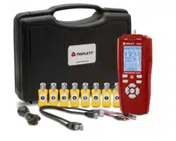
• The built-in tone generator and the included Video and Data remote identifiers can be used to
quickly locate cables in wiring closets and patch panels.
• In addition, we have added many practical functions, you can get the voltage on telephone wire
and the POE voltage, you also can locate a cable connection to a switch port by blinking the
switch’s Link LED and the tester will display the advertised speed of the port and the cable pairs
used to transmit.
• The Cable/Network Tester measure cable distance to open or short (TDR), and perform detailed
wire-mapping including Skew, Delay & Ohms.
• Measures network speed capabilities
• Store and print up to 250 Reports.
• With proper use, this tester will provide many years of reliable service.
2.Safety
WARNINGS
• Do not connect the tester to a live circuit, exposure to voltage can damage the tester.
• Do not modify or try to repair the tester, no serviceable parts are inside.
• Do not use the tester in a wet environment or during electrical storms.
• Do not use the tester near explosive gases, dust or vapor.
• Visually inspect an RJ plug before inserting it into the tester, poorly terminated plugs may damage
the jacks on the tester.
5
Cabl
e/Network T
es
ter
6
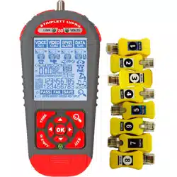
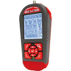
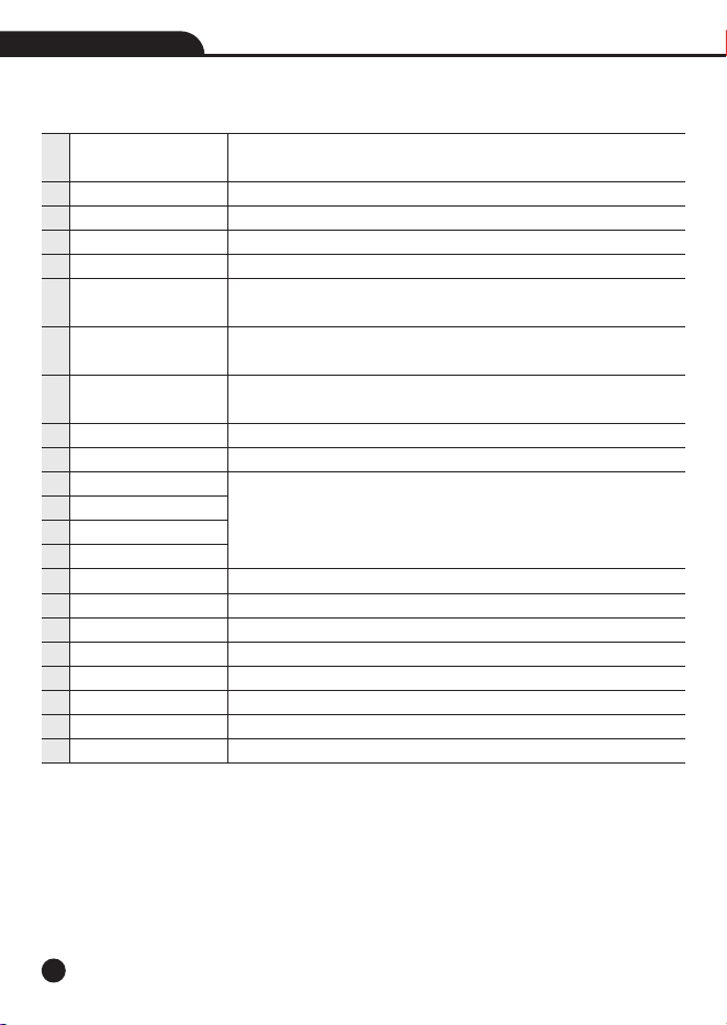
4.Description
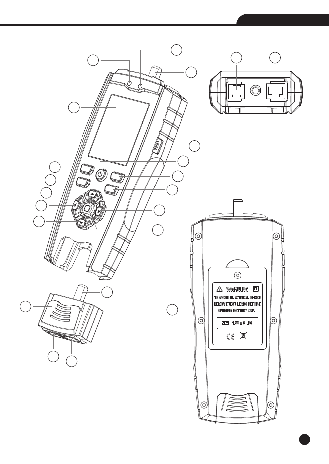
4-1.Meter Description
Cable/Network Tester
Note: If you press the EXIT Button and Down Button hold the 1 seconds, you can choose whether
to turn on the buzzer.
Link LED
Volt LED
Video-F Connector
LCD Display
Micro USB Interface
TONE Button
ID Button
Power/Backlight Button
DETAIL Button
EXIT Button
Up Button
Left Button
Down Button
Right Button
OK Button
Detachable Remote
Voice-RJ11/RJ12 Jack
Data-RJ45 Jack
Video-F Connector
Voice-RJ11/RJ12 Jack
Data-RJ45 Jack
Battery Cover
If an active port is connected, the LED will light up during the network
speed test.
If the device port is connected to a high voltage, this LED will light up.
Port for connecting coaxial cable.
Display the operation interface and measurement results.
Connect to the computer to view saved data.
Transmit analog tones on the wires of the terminated cable for
positioning the wires.
You can locate the wires by the remote IDs, the number that appears
corresponds to the number on the Remote ID.
Short press to adjust the backlight, long press to turn off the machine
when turning on.
Press to view more information during cable testing.
Exit the current functional test.
Use the Left/Right arrows to select the cable or cabled device that
you are working with.
Use the Up/Down arrows to select the specific test or the specific
device to be tested.
Determine actions and save results.
Used for testing cables.
Port is commonly used to connect phone lines.
Port for connecting network cables.
Port for connecting coaxial cable.
Port is commonly used to connect phone lines.
Port for connecting network cables.
1
2
3
4
5
6
7
8
9
10
11
12
13
14
15
16
17
18
19
20
21
22
7
Cable/Network Tester
Link
Volts
Cable/Network Tester
TONE
DETAIL
ID EXIT
1
2
3
4
5
6
7
9
10
8
12
11
14
13
15
17 18
22
20
21
16
19
8
Cable/Network Tester
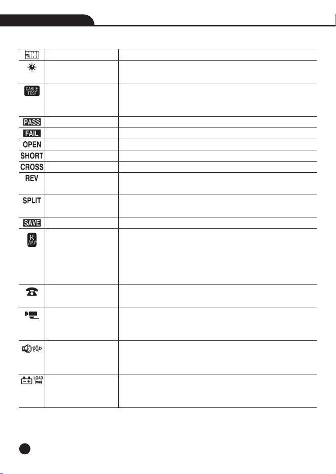
4-2.Symbols Used on LCD Display
Length Test
VOP Adjustment Knob
Cable Test
Return Loss Quality
Test
CCTV/Vpp (peak to peak
voltage) Test
Speaker Popper
Alarm Battery Test
You can get the length of the cable and distance to open or short.
The tester has adjustable VOP so you can tune the tester to the
cable, most people stick to the default values.
Include cable diagram, Pass/Fail, timing (delay, skew) and
impedance (ohms), the wiring diagram will be displayed in the
area below the LCD.
Indicates proper wiring on cable being tested.
Indicates wiring error on cable being tested.
Appears when one or more pairs are open.
Indicates that two or more wires are shorted to each other.
Appears when the tester detects a properly wired cross over cable.
Indicates the connections on one or more pairs is reversed at one
of the cable.
Appears when the tester detects the signal is split between two
or more pairs.
Save the test data.
Return Loss Quality
tests for load mismatches that affect the
wire’s power and data transfer capability.
It is a powerful quality test that should be used if quality problems
are suspected with the cable.
The RLQ test works with DATA cables and VIDEO cables.
Detect central office telephone connections (48V), display voltage
and cable location.
CCTV systems require approximately 1Vpp to the DVR for reliable
recording, it measures and displays the Vpp of video signal,
perfect for quick debugging of CCTV systems.
Locate speakers by audibly “popping” them, connect the alligator
clips to the loose speaker wires using the RJ45
/Clips adapter, the
speaker will make and audible popping sound.
Test alarm system and other backup batteries by doing a loaded
battery test, better than a voltmeter test because this test places
a 100mA load on the battery.
9
Cable/Network Tester
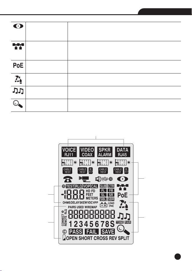
Port Blink Cable
Detection
Advertised Speed/Pairs
Used
Power Over Ethernet/
Pairs Used
Tone Cable Detection
Details avaliable
Locate a cable connection to a switch port by blinking the switch’s
Link LED, the green link LED on the switch will slowly blink so you
can locate the cable end, port's green link LED will blink.
Plug into any active port (computer, switch, VoIP, access point)
and display its capabilities (10,100,1000 HD, FD) and the cable
pairs used to transmit.
Detect PoE voltage and display its amplitude and location on the
cable (midspan, endspan or both).
Hammering says the test is active.
Locating the far end of a cable, place a tone on the near end of
the cable with the unit.
When conducting cable testing, you can see more message, when
lit, press Details glass (and use down arrow to show more results).
Select Cable Type
Select Test
Working Flag
Test Results
Cable Wiremap

10
Cable/Network Tester
5.Operation
5-1.Length Test
1.Press the Power Button to turn tester on.
2.Connect one end of the cable to the appropriate port, located at the top of the main tester body,
leave the other end of the cable unterminated.
3.Select the Length icon “ ” below the test cable and press the OK Button to enter Length
mode.
4.Press the Up Button and the Down Button repeatedly to select the pair of wires that should be
measured, the first functional pair is chosen by default.
5.Press the Left or Right Buttons to switch units (feet and meters).
6.Read the length measurement as shown.
Note: A voice or data cable under test can be unterminated (open) or terminated by an RJ45 remote,
if it is terminated by the self-storing remote, the reading will be 1 to 2 ft. greater than the actual
measurement, in this case, subtract 1 to 2 ft. from the reading to obtain the actual measurement.
• When you move the cursor to the Length icon for each of the cable types, you can see the VOP
value, VOP (Velocity of Propagation) is typically represented as a percentage of the speed of light,
as an example, a VOP of 67% means the velocity of the cable is 67% of the speed of light, the
VOP value is the foundation of length measurement accuracy.
• There are two ways to change the VOP value, each cable type has its own VOP, use the VOP
Adjustment Knob icon (to the right of the Length icon) to set the length constant based on a
known value (for example, as given by the cable manufacturer) (use the VOP icon) or let the unit
determine the VOP of your cable by connecting a sample of the cable to the unit(use the CAL i
con).
• Adjust manually (“VOP”) or Calibrate (“CAL”) the tester from a known length of cable (no remote
connected), minimum length required 100” (35m), use the Left/Right arrows to select method
you want, use the Up/Down to change the value, when you use the CAL icon, you can use the Left/
Right arrows to change the value added each time, finally you can press the OK Button to save
the VOP value that you set.

11
5-2.Cable Test
1.Press the Power Button to turn tester on.
2.Connect one end of the cable to the appropriate port, located at the top of the main tester body,
connect the other end of the cable to the corresponding port on the remote.
3.Select the Cable Test icon “ ” below the test cable and press the OK Button to start the test.
4.Then the test result will display: Pass/Fail, Wire map, Opens, Shorts, Split Pairs, the min length
of the cable, when both ends of the tested network cable are connected with shielding, “S” is
displayed.
5.When the Details glass lit, press the DETAIL Button and use down arrow to show more results,
press the OK Button to save the data for this measurement.
6.Press the EXIT button when done.
5-3.RLQ Test
• Return Loss Quality tests for load mismatches that affect the wire’s power and data transfer
capability.
• It is a powerful quality test that should be used if quality problems are suspected with the cable.
• The RLQ test works with DATA cables and VIDEO cables.
1.Connect cable to Main unit and green RLQ Remote.
2.Select and start Test APP “ ”.
3.View test results, the result is displayed as a single integer of 0, 1, or 2, “0” indicates the cable
measures as if it is unterminated, “2” indicates it is perfectly terminated, Quality issues can
arise in a transmission cable (Cat5/6 or coax) for a variety of reasons, including physical damage
caused by crushing or bending the cable too sharply, improper termination, moisture intrusion,
etc.
5-4.Phone Devices Test
Use: Detect central office telephone connections (48V), display voltage and cable location.
1.Connect the cable to the RJ11/RJ12 connector on the unit.
2.Select the Telephone APP “ ” and start the test.
Result: The unit scans the 6 pins and displays up to 3 pairs of central office connections; the
pairs used (typically 3,4; 2,5; and 1,6); and the amplitude of voltage on each pair.
Cable/Network Tester

12
5-5.Video Devices Test
CCTV systems require approximately 1Vpp to the DVR for reliable recording, this APP measures
and displays the Vpp of video signal, perfect for quick debugging of CCTV systems.
1.Connect the CCTV camera video output to the coax connector on the Unit.
2.Select the Camera icon “ ” and press OK.
3.The voltage LED will light and voltage is displayed when connecting a valid cable.
Note: The voltage display varies with the whiteness of the camera's image.
Note: The CCTV/Vpp APP can also be used to detect CATV (cable TV) signals, but some CATV
signals may be too small for the unit to detect.
5-6.Speaker/Alarm Devices Test
Use these Test APPS if you are working with speakers, Dolby surround sound installations, or
testing the quality of alarm batteries, the operation is the same for all APPS.
1.Connect the RJ45 jack to the speaker wires or alarm battery using the RJ45/alligator clips.
2.Select and start Test.
3.Hammering says it’s active, EXIT returns to menu.
5-6-1.Speaker Popper
Use: Locate speakers by
audibly “popping” them.
1.Connect the alligator clips to the loose speaker wires using the RJ45/Clips adapter included
2.Select the icon “ ” and press OK.
3.Result: The speaker will make and audible popping soun
d
Cable/Network Tester
12

13
5-6-2.Alarm Battery Test
• T
est alarm sy
stem and other backup batteries b
y doing a loaded batter
y test, better than a
voltmeter test because this test places a 100ma load on the battery.
1.Use RJ45/Alligator clips to connect the battery to the RJ45 port.
2.After test starts, the battery voltage will be displayed on the screen, and there is no load applied
at this time.
3.Pressing the OK Button puts a 100ma load on the battery, the icon will flash.
• F
or the batter
y to be OK, the batter
y v
oltage should r
emain stable after the load is applied.
5-7.Network Device Testing
Use these Test APPS if you are working with switches, NIC cards, PoE, IP cameras, VoIP phone
and access points... any computerized device, the operation is the same for all APPS.
1.Connect the RJ45 jack to the device (use included patch cable).
2.Select and start Test.
3.Hammering sa
y
s it
’
s activ
e, EXIT r
eturns to menu.
5-7-1.Port Blink Cable Detection
1.Select the icon “ ” to locate a cable connection to a switch port by blinking the switch’s
Link LED.
2.The green link LED on the switch will slowly blink so you can locate the cable end.
3.I
n
o
r
d
e
r
t
o
d
i
s
t
i
n
g
u
i
s
h
i
t
f
r
o
m
t
h
e
fl
a
s
h
i
n
g
g
r
e
e
n
l
i
g
h
t
t
h
a
t
o
p
e
r
a
t
e
s
n
o
r
m
a
l
l
y
,
we
p
r
ov
i
d
e
a
s
e
c
o
n
d
flashing frequency, press the Down Arrow Button, and the green light will flash once every 5
seconds, at this point, “t2” will be displayed on the screen, the Up and Down arrows can switch
the flashing frequency.
5-7-2.10/100/1000/10000Mbase-t
Detection/Adv
ertised Speed/P
airs Used
1.Plug into any active port (computer, switch, VoIP, access point) and select the icon “ ” to
start the test.
2.Then the unit will display the advertised speed of the port (10,100,1000,,10000 HD, FD)
and the cable
pairs used to transmit
.
5-7-3.Power Over Ethernet/Pairs Used
1.Select the icon “ ” to detect PoE voltage and display its amplitude and location on the cable
(midspan, endspan or both).
2.Press the OK Button to start the test and the PoE voltage will display (just like a voltmeter) as
are the cable pairs used (1,2 3,6 or 4,5 7,8 or both).
Cabl
e/Network T
es
ter

14
5-8.Tone Cable Detection
Locating the far end of a cable, place a tone on the near end of the cable with the unit and detect
it on the far end with a Tone Probe (available separately).
1.Plug the cable to be “toned” into the socket.
2.Select the proper cable type and then press the TONE Button.
3.Choose from 3 tones (up or down arrow) and/or the pairs that you wish to tone (right arrow and
select “Pair” and down arrow to scroll through pairs).
4.Detect tone on the far end using a tone probe.
5.Press EXIT when done.
5-9.Wall Jack Identifiers
Large wiring jobs end up with unlabled runs, plugging these wall jack identifiers into each socket
makes identifying the wall jack’s location a snap.
1.Connect the unidentified cable into the correct jack.
2.Press the button labeled “ID” to start the scan.
3.Press EXIT when done.
Cable/Network Tester
15
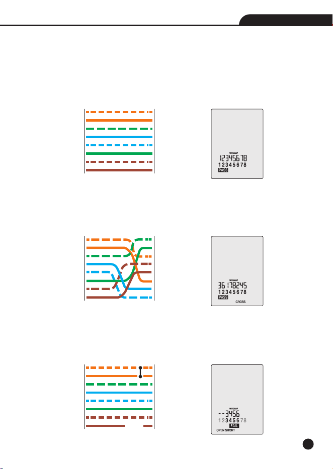
6.Wiring and Display Examples
6-1.T568B Data Cable Properly Wired
• PASS appears on the display indicating a properly wired cable.
• The pin numbers on the top row agree with the bottom row indicating proper continuity.
Note: Both the T568A and T568B wiring standard will test the same as long as the same standard
is used on both ends of the cable.
6-2.T568B Cross Over Data Cable Properly Wired
• The pairs cross over (transmit to receive and receive to transmit).
• PASS and CROSS appear on the display and the pin numbers on the bottom row indicate the
corresponding cross over to the pin numbers on the top row.
6-3.T568B Data Cable with a Shorted And Open Pair
• Pins 1 and 2 are shorted and the pair on pins 7 and 8 is open.
• FAIL, OPEN and OPEN appear on the display and the pins with wiring errors will flash, the dash
will appear above the short circuit pin, and the blank will appear above the open circuit pin.
Cable/Network Tester
1
2
3
4
5
6
7
8
1
2
3
4
5
6
7
8
TESTER
REMOTE
1
2
3
4
5
6
7
8
1
2
3
4
5
6
7
8
TESTER
REMOTE
1
2
3
4
5
6
7
8
1
2
3
4
5
6
7
8
TESTER
REMOTE
Open
Short
16
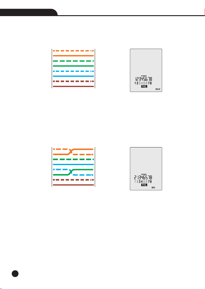
6-4.T568B Data Cable with Split pairs
• There is a split between the pairs on pins 3, 4 and 5, 6.
• FAIL and SPLIT appear on the display and the pin numbers with the split will flash.
6-5.T568B Data Cable with Reversed Pair and Crossed Connection
• The pair on pins 1 and 2 is reversed and the wires on pins 5 and 6 are crossed at one end of the
cable.
• Fail will appear on the display indicating a defective cable, the pins with wiring errors will flash.
• Pins 2 and 1 shown above pins 1 and 2 indicate a reversal on the Orange pair; Pins 6 and 5 shown
above 5 and 6 indicate a crossed connection.
Cable/Network Tester
1
2
3
4
5
6
7
8
1
2
3
4
5
6
7
8
TESTER
REMOTE
1
2
3
4
5
6
7
8
1
2
3
4
5
6
7
8
TESTER
REMOTE
17
Cable/Network Tester
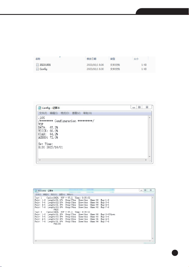
7.Data Export
• After test is complete, press the Details button followed by the OK button to save the test, the
maximum storage capacity is 250 tests.
• You can connect to the computer through a micro USB cable and display the exported data files
in the folder.
• By clicking on the “Config.txt” file, you can set the VOP value of each cable and the time of the
machine, save the file to save the settings.
• If you want to delete the saved data, you can directly delete the file and unplug the USB cable
again.
• Other files are saved results separated by dates, after clicking on it, the cable category, VOP,
save time, line sequence diagram, length, delay, skew, and impedance will be displayed.

18
Cable/Network Tester
8.Battery Replacement
1.Loosen the one Phillips screw.
2.Lift the battery door compartment, allowing access to the battery compartment.
3.Replace the three AA batteries.
4.Re-assemble the meter.
Note: Do not operate the tester with the battery door removed.
9.Maintenance
This tester is designed to provide years of dependable service, if the following care instructions
are performed:
• Keep the tester dry, if it gets wet, wipe it off.
• Use and store the tester in normal temperatures, temperature extremes can shorten the life of
the electronic parts and distort or melt plastic parts.
• Handle the tester gently and carefully, dropping it can damage the electronic parts or the case.
• Keep the tester clean, wipe the case occasionally with a damp cloth.
• Do not use chemicals, cleaning solvents, or detergents.
• Use only fresh batteries of the recommended size and type, remove old or weak batteries so they
do not leak and damage the unit.
• If the tester is to be stored for a long period of time, the battery should be removed to prevent
damage to the unit.
Phillips Screw
Battery Door


Rev.231024
Cable/Network Tester