Please read this manual before switching the unit on.
Important safety information inside.
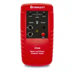
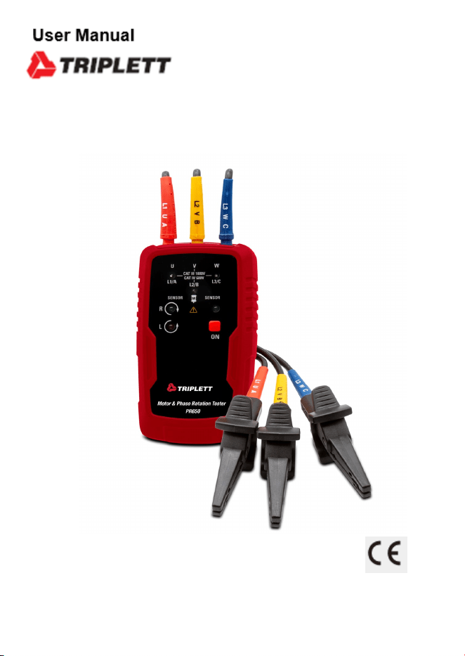
PR650
3 Phase Sequence and Non-Contact Motor Rotation Tester

3
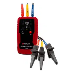
Motor & Phase Rotation Indicator
Page
4
4
5
5
6
7
7
8
9
9
9
10
Content
1.Introduction.................................................................................
2.Safety Information........................................................................
3.Symbols.......................................................................................
4.Ships with the Following Items.....................................................
5.Meter Description.........................................................................
6.Operation.....................................................................................
6-1.Determine Rotary Field Direction.............................................
6-2.Non-Contact Rotary Field Indication........................................
6-3.Determine the Motor Connection.............................................
6-4.Magnetic Field Detection.........................................................
7.Battery Replacement....................................................................
8.Specifications..............................................................................

4
Motor & Phase Rotation Indicator
1.Introduction
The Motor and Phase Rotation indicator is a handheld, battery-operated instrument designed to
detect the rotary field of three-phase systems and determine motor-rotation direction.
2.Safety Information
CAUTION identifies conditions and actions that may damage the phase rotation indicator.
WARNING identifies conditions and actions that pose hazard to the user.
To avoid possible electric shock or fire, do the following:
• Read the following safety information carefully before using or servicing the instrument.
• Adhere to local and national safety codes.
• Individual protective equipment must be used to prevent shock and injury.
• Use of instrument in a manner not specified by the manufacturer may impair safety features/
protection provided by the equipment.
• Avoid working alone.
• Inspect the test leads for damaged insulation or exposed metal. Check test lead continuity,
damage leads must be replaced, do not use the phase Rotation indicator if it looks damaged.
• Be careful when working above 30V ac rms, 42V ac peak and 60V dc, Such voltages pose a shock
hazard.
• When using the probes, keep fingers away from probe contacts, keep fingers behind the finger
guards on the probes.
• Measurements can be adversely affected by impedances of additional operating circuits connected
in parallel or by transient currents.
• Verify operation prior to measuring hazardous voltages (voltages above 30V ac rms, 42V ac peak
and 60V dc).
• Do not use the phase rotation indicator with any of the parts removed.
• Do not use the phase rotation indicator around explosive gas, vapor, or dust.
• Do not use the phase rotation indicator in a wet environment.
5
Motor & Phase Rotation Indicator
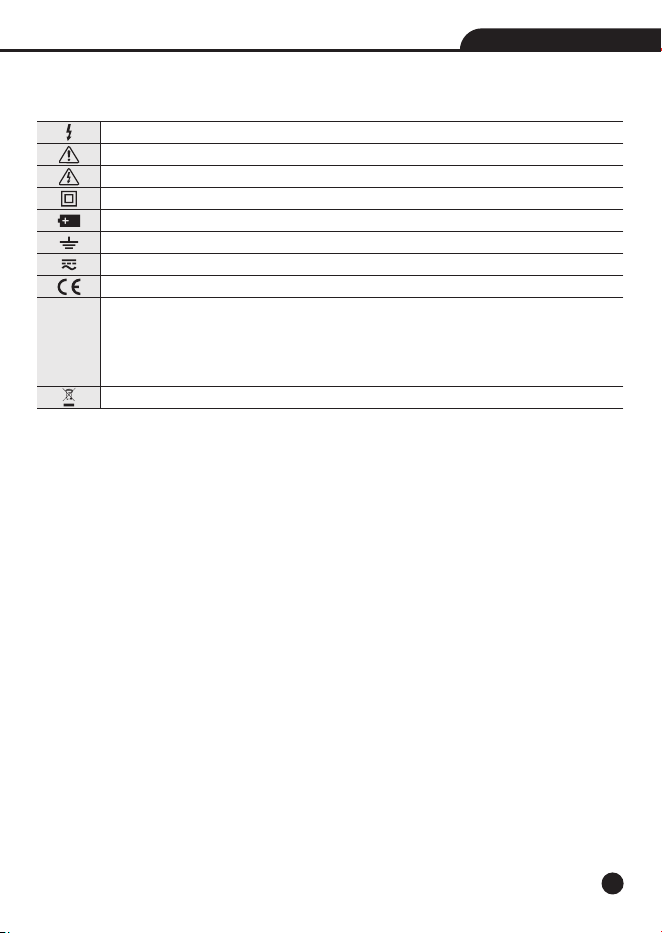
3.Symbols
The following symbols appear on the Motor and Phase Rotation indicator or in this manual.
4.Ships with the Following Items
• 3 Test Leads
• 3 Test Probes
• 3 Alligator Clips
• 9V Battery
• Users Manual
Risk of electric shock
Risk of Danger, Important information see manual.
Hazardous Voltage.
Equipment protected by double or reinforced insulation
Battery
Earth
AC or DC
Conforms to EU directives
Overvoltage (Installation) Category III, Pollution Degree 2 per ICE 1010-1 refers to the
level of Impulse wishstand voltage protection provided. Equipment of Overvoltage
Category III is equipment in fixed installations (e.g.,electricity meter and primary
over-current protection equipmetr).
Recycling information
CAT III
6
Motor & Phase Rotation Indicator
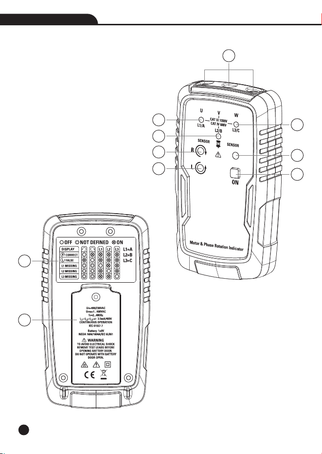
5.Meter Description
1-Test Lead Input Jack
2-L1 Indicator
3-L2 Indicator
4-L3 Indicator
5-Clockwise Rotation Indicator
6-Counter Clockwise Rotation Indicator
7-ON/OFF Indicator
8-ON/OFF Button
9-Brief Instructions on Instrument Rear
10-Battery Cover
1
2
3
4
5
6
7
8
9
10
7
Motor & Phase Rotation Indicator
6.Operation
6-1.Determine Rotary Field Direction
1.Connect one end of the test leads to the Motor and Phase Rotation indicator, make sure the L1,
L2 and L3 test leads are connected to the corresponding input jacks.
2.Connect the test probes to the other end of the test leads.
3.Connect the test probes to the three mains phases, press the ON/OFF Button, the green ON
indicator shows that the instrument is ready for testing.
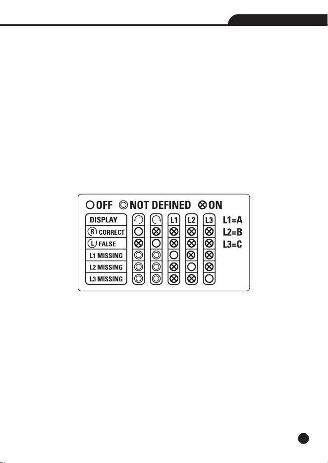
4.Either the Clockwise or Counter Clockwise Rotary indicator illuminates showing the Type of rotary
field direction present.
5.The rotary indicator lights even if the neutral conductor, N, is connected instead of the Test lead
input jacks.
6.Refer to Figure (Also shown on the back of the Motor and Phase Rotation indicator) for more
information.
8
Motor & Phase Rotation Indicator
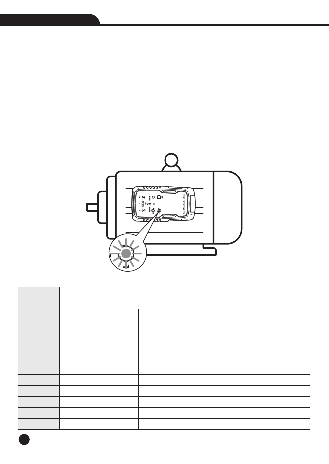
6-2.Non-Contact Rotary Field Indication
1.Disconnect all test leads from the Motor and Phase Rotation indicator.
2.Position the Indicator on the motor so that it is parallel to the length of the motor shaft, the
Indicator should be one inch or close to the motor.
3.Press the ON/OFF Button, the green ON indicator shows that the instrument is ready for testing.
4.Either the Clockwise or Counter Clockwise Rotary indicator illuminates showing the type of rotary
field direction present.
Note: The indicator will not operate with engines controlled by frequency converters. The bottom
of the Motor and Phase Rotation indicator should be oriented towards the drive shaft. See the
Orientation Symbol on the Motor and Phase Rotation indicator.
See Table for the minimum motor diameter and number of pole pair to obtain a reliable test result.
Rotary Number of Rotary Field (1/min)
at Frequency (Hz)
16 2/3
1000
500
333
250
200
167
125
100
83
62
Angel Between Poles
°
60
30
20
15
12
10
7.5
6
5
3.75
Min. Ø of Motorcase
cm
5.3
10.7
16.0
21.4
26.7
32.1
42.8
53.5
64.2
85.6
Number of
Pole Pair
1
2
3
4
5
6
8
10
12
16
50
3000
1500
1000
750
600
500
375
300
250
188
60
3600
1800
1200
900
720
600
450
360
300
225

9
Motor & Phase Rotation Indicator
6-3.Determine the Motor Connection
1.Connect one end of the test leads to the Motor and Phase Rotation indicator, make sure the L1,
L2 and L3 test leads are connected to the corresponding jack.
2.Connect the alligator clamps to the other end of the test leads.
3.Connect the alligator clamps to the motor connections, L1 to U, L2 to V, L3 to W.
4.Press the ON/OFF Button, the green ON indicator shows that the instrument is ready for testing.
5.Turn the motor shaft half a revolution towards the right.
Note: The bottom of the Motor and Phase Rotation indicator should be oriented towards the drive
shaft. See the Orientation Symbol on the Motor and Phase Rotation indicator.
Note: Either the Clockwise or Counter Clockwise Rotary indicator illuminates showing the type of
rotary field direction present.
6-4.Magnetic Field Detection
• To detect a magnetic field, place the Motor and Phase Rotation indicator to a solenoid valve.
• A magnetic field is present if either the Clockwise or the Counter Clockwise Rotary indicator
illuminate.
7.Battery Replacement
The Motor and Phase Rotation indicator uses a 9V battery (supplied), To replace the battery,
follow these steps.
1.Place the Motor and Phase Rotation indicator face down on a nonabrasive surface and loosen
the battery-door screw with a screwdriver.
2.Life the battery access lid away from the Motor and Phase Rotation indicator.
3.Observe the battery polarity shown in the battery compartment.
4.Secure the battery access lid back in position with the screw.
Note: The Motor and Phase Rotation indicator contains alkaline batteries. Do not dispose of these
batteries with other solid waste. Used batteries should be disposed of by a qualified recycler or
hazardous materials handler.

10
Motor & Phase Rotation Indicator
8.Specifications
Determine Rotary Field Direction
Nominal Voltage Rotary Direction
Nominal Voltage phase indirection
Frequency Range (fn)
Test Currents (In per phase)
Non-Contact Rotary Field Indication
Frequency Range (fn)
Determine the Motor Connection
Nominal Test Voltage (U me)
Nominal Test Currents (In per phase)
Frequency Range (fn)
Electrical Specifications
Battery
Current Consumption
Battery life Minimum
Safety Specifications
Electrical Safety
Maximum Operating Voltage (Ume)
Protection Levels
Environmental
Operating Temperature
Operating Humidity
Operating Altitude
Pollution Degree
Type of protection
Mechanical Specifications
Size (HxWxD)
Weight
1 to 400VAC
120 to 400VAC
2 to 400Hz
Less than 3.5mA
2 to 400Hz
1 to 400VAC
Less than 3.5mA
2 to 400Hz
9V alkaline, IEC 6LR61
Max 20mA
1 year for average use
Meets DIN VDE 0411,IEC 61010 DIN, VDE 0413-7, IEC
61557-7/EN 61557-7
400 V AC for all ranges
CAT III 1000V and CAT IV 600V
0 to 40°C
15% to 80%
2000m
2
IP 40
135x75x31mm.
173.9g (With the battery)