OPERATING
INSTRUCTIONS
PHASESEQUENCE
ANDOPENPHASE
INDICATOR
#61-520
HOW TO CHECK PHASE SEQUENCE (cont’d)
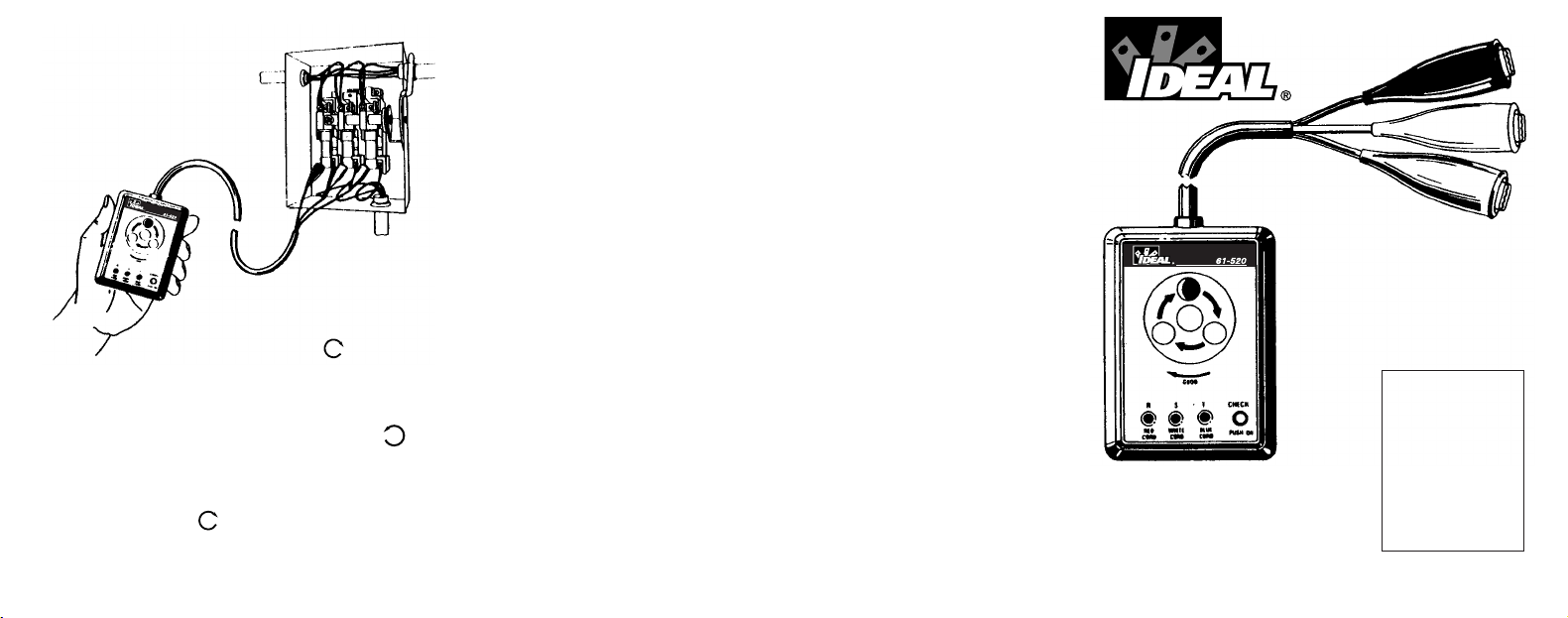
Fig. 3
IDEAL INDUSTRIES,INC.
Sycamore,IL60178,U.S.A.
800-435-0705CustomerAssistance
www.idealindustries.com
ND-1714-2
PLEASEREAD
CAREFULLY
Misuse and abuse of
these instructions can-
not be prevented by any
printed word and may
cause injury and or
equipment damage.
Please follow these
instructions faithfully and
adhere to all standard
industry safety rules.
ShownApprox.
1/3ActualSize
WARRANTYSTATEMENT
Thistesteriswarrantedtotheoriginalpurchaseragainstdefectsin
materialand workmanshipfortwo yearsfromthe dateofpurchase.
During this warranty period, IDEAL INDUSTRIES, INC. will, at its
option,replace or repair the defective unit, subject toverification of
thedefectormaltifunction.Thiswarrantydoesnotcoverfuses,bat-
teriesordamagefromabouse,neglect,accident,unauthorizedrepair,
alteration,orunreasonableuseoftheinstrument.
Anyimpliedwarranties arising out of the saleofanIDEALproduct,
includingbut limited toimpliedwarranties of merchantebilityandfit-
nessforaparticularpurpose,arelimitedtotheavobe.Themanufac-
turershallnotbeliableforlossofuseoftheinstrumentorotherinci-
dentalorconsequentialdamages,expenses,oreconomicloss,orfor
anyclaimorclaimsforsuchdamage,expensesoreconomicloss.
Statelawsvary,sotheabovelimitationsorexclusionsmaynotapply
toyou.Thiswarrantygivesyouspecificlegalright,andyoumayalso
haveotherrightswhichvaryfromstatetostate.
IDEALINDUSTRIESINC.
Attention:RepairDept.
1000ParkAve.
Sycamore,IL60178
1
Thewarrantyisnotapplicableiftheinstrumenthasbeenmisused,
abused,subjectedtoloadsinexcessofspecifications,hashadunau-
thorizedrepairorhasbeenimproperlyassembledorused.
6. If the rotation of the disc is
COUNTER-CLOCKWISE
,release
'ON' button and transpose (interchange)the connections of any
two clips to the lines.
7.
Press the 'ON' button again, making certain that all 3 lamps are lit
(no open phases), and check direction of the rotating disc, which
will be
CLOCKWISE .
Release 'ON' button at end of test.
5. If all 3 lamps are lit, check the direction of the
rotating disc on the front panel. If it is in a
CLOCKWISE direction , the Phase Se-
quence is R, S, and T, in order of the lines
where the Red, White and Blue clips are con-
nected.
Release the
'ON' button at conclusion of test.
IMPORTANCE OF PHASE SEQUENCE INDICATION
The Model 61-520 is a positive action electrical tester and will indicate
both Phase Sequence and Phase Continuity instantly and accurately.
PACKAGING
Packed in handy unit box, complete with Pouch, Form ND-1714 Operating
Instructions and Warranty Card, all ready to use.
HOW TO CHECK PHASE SEQUENCE (cont’d)
Fig. 2
CONTENTS
Page
2. Importance of Phase Sequence Indication; Specifications; Packaging
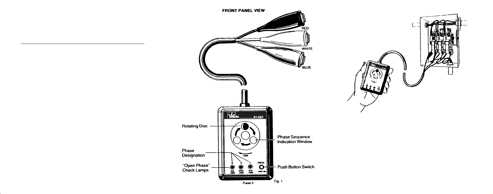
3. Front Panel View
4. How to Check Phase Sequence
5. How to Check Phase Sequence(cont'd.)
6. Warranty; Do's and Don'ts
Phase Sequence is the order in which the phase voltages come on the
system.
If, during repair or maintenance, two lines are transposed (interchanged)
from their original positions, the Phase Sequence will be reversed. This, in
turn, will reverse the direction of all 3-Phase motors on the system.
This can cause severe personal, property and equipment damage especially
where rotating machinery is used for woodworking, metalworking, escalators,
elevators, automation, etc.
Hence, when any repairs or maintenance is made on 3-Phase systems, or
when paralleling 3-Phase Transformers or 3-Phase banks, the phase
sequence of each must be in the same order.
SPECIFICATIONS
Voltage - to 600V on 3-Phase Power Source
Duty Cycle - CONTINUOUS TO 500V
5 MINUTES MAX. FROM 500V TO 600V
Frequency - 50/60Hz
Insulation
Test - 2,200V AC for 1 minute
Dimensions - 4.24"L X 3"W X 1.6" D (106X75X40mm)
Weight - 12
1
/2
Oz. (350g.)
Line Cord - 60"
2.
Connect the 3 alligator clips to the 3-Phase Power source being
checked for Phase Sequence. The positions of the clips on the 3
lines is optional.
3.
Press the 'ON' button in lower right corner of front panel, keeping
it depressed throughout the test.
4.
If all 3 lamps are lit, it signifies NO OPEN PHASES and the Phase
Sequence can then be checked.
However, if any of the lamps are NOT lit, the Phase Sequence
Indicator will not operate. Check to determine cause of the open
phase and correct before proceeding with the test.
1. Please note the 3 'Open Phase' Check Lamps
at the bottom of the front panel.
The alligator clip with Red Insulator is internally
connected to the left lamp with Phase Designa-
tion 'R'; the White Insulator to the middle lamp
with Phase Designation 'S'; the Blue Insulator
to the right lamp with Phase Designation 'T'.