All rights reserved.
Specifications are subject to change without notice.
User Manual

LIMITED WARRANTY
AND LIMITATION OF LIABILITY
Customers enjoy one-year warranty
from the date of purchase.
This warranty does not cover fuses,
disposable batteries, damage from
misuse accident, neglect, alteration,
contamination, or abnormal conditions
of operation or handling, including
failures caused by use outside of the
product's specifications, or normal wear
and tear of mechanical components.

Table of Contents Page
Introduction..........................................................1
Safety Information................................................1
Instrument Overview............................................3
LCD Display...................................................3
Function Buttons............................................5
Rotary Switch.................................................7
Input Terminals..............................................9
Measurements Instruction..................................10
Measure AC/DC Voltage..............................11
Measure AC/DC Current..............................11
Measure Resistance.....................................12
Test for Continuity........................................13
Test Diodes..................................................13
Measure Capacitance..................................14
Measure F requency.....................................15
Measure Duty Cycle.....................................15
Measure Temperature .................................16

Square waves output....................................16
2000V high voltage measurement................17
NCV....................................................17
Maintenance.......................................................18
Clean the Product.........................................18
Replace the Ba tteri es...................................18
Replace the Fuses.......................................19
Specifications.....................................................20
General Specifications.................................20
Mechanical Specifications............................20
Environmental Specifications.......................21
Electrical Specifications......................................22

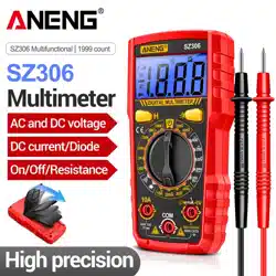
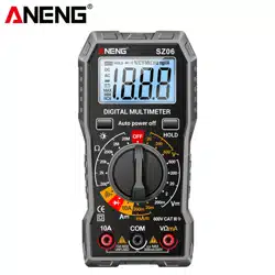
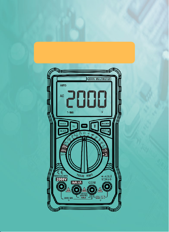
Introduction
This product is a battery-powered, true-rms, auto-
ranging digital multimeter with a 6000 counts
LCD display and a backlight.
Safety Information
To avoid possible electrical shock, fire, or
personal injury, please read all safety information
before you use the product. Please use the
product only as specified, or the protection
supplied by the product can be compromised.
• Examine the case before you use the product.
Look for cracks or missing plastic. Carefully look
at the insulation around the terminals.
• The measurement must be made with correct
input terminals and functions and within the
allowable measuring range.
1

• Do not use the product around explosive gas,
vapor, or in damp or wet environments.
• Keep fingers behind the finger guards on the
probes.
• When the product has already been connected
to the line being measured, do NOT touch the
input terminal that is not in service.
• Disconnect the test leads from the circuit before
changing the mode.
• When the voltage to be measured exceeds 36V
DC or 25V AC, the operator shall be careful
enough to avoid electric shock.
• Misuse of mode or range can lead to hazards,
be cautious. “ ” will be shown on the display
when the input is out of range.
• Low level of a battery will result in incorrect
readings. Change the batteries when battery
level is low. Do not make measurements when
the battery door is not properly placed.
2
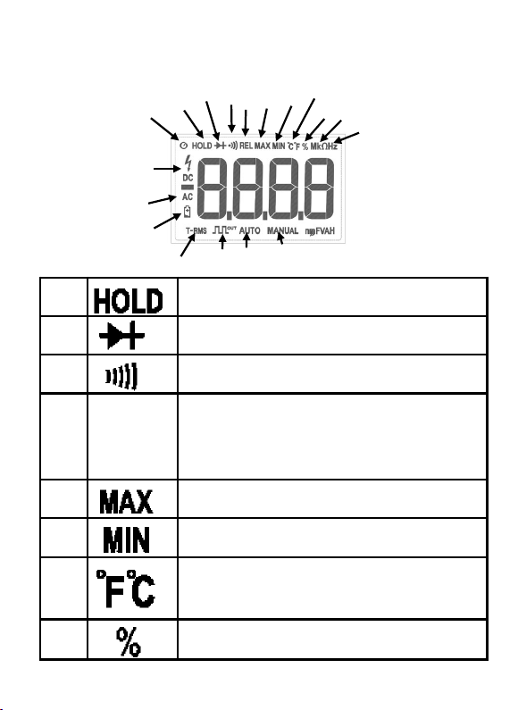
LCD Display
①
Display freezes present reading.
②
Diode test.
③
Continuity test.
④
REL
The product measures both
sinusoidal and non sinusoidal ac
waveforms accurately.
⑤
Display shows maximum reading.
⑥
Display shows minimum reading.
⑦
Temperature test.
(Fahrenheit or Celsius)
⑧
Duty cycle test.
Instrument Overview
3
①
②
③
④
⑤
⑥
⑦
⑧
⑨
⑩
⑪
⑫
⑬
⑭
⑮
⑯
⑰
⑱
⑲
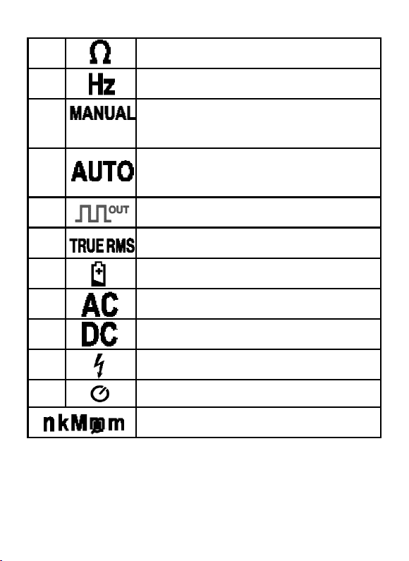
⑨
Resistance test. (Ohm)
⑩
Frequency test. (Hertz)
⑪
Manual range. The user selects
the range.
⑫
Auto range. The product selects
the range with the best resolution.
⑬
Square waves output
⑭
True RMS
⑮
Low battery. Replace batteries.
⑯
Alternating current.
⑰
Direct current.
⑱
Unsafe Voltage.
⑲
Auto power off.
Measurement units.
4
5
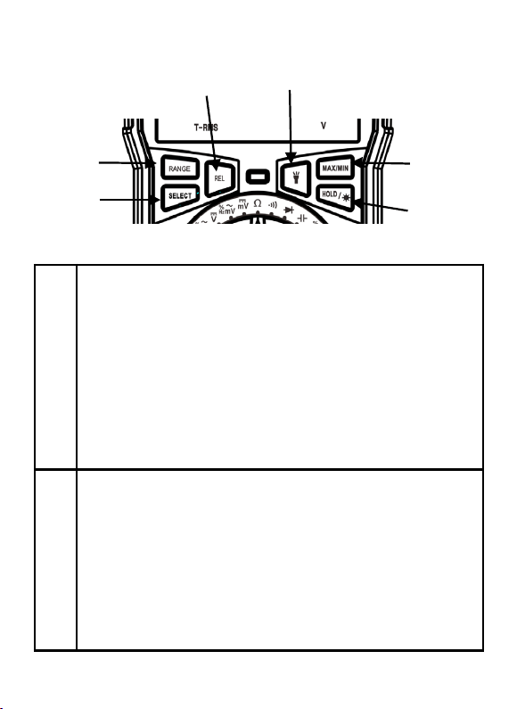
Function Buttons
①
Selects alternate measurement modes on a
rotary switch setting, including:
1. Frequency/Duty Cycle
2. DC mA/AC mA
3. DC μA/AC μA
4. Celsius/Fahrenheit
5. Square waves output
②
Push once to hold the current reading on the
display; push again to continue normal
operation.
Push for more than 2 seconds to turn on the
backlight; long-push again to turn off or the
backlight automatically turns off after 2
minutes.
①
②
③
④
⑤
⑥

③
Push this button to enter the relative
mode. The product will store the present
reading as a reference for subsequent
readings. The display is zeroed, and the
stored reading is subtracted from all
subsequent readings. Push again to exit
the relative mode.
④
Keep pushing this button to enter the
NCV testing mode. In this mode, you
have to push the button always.
⑤
Push once to turn on the flashlights,push
once more to turn off the flashlight.
⑥
Push to toggle between the MAX and
the MIN mode. To exit MAX/MIN mode,
push the button for more than 2 seconds
6
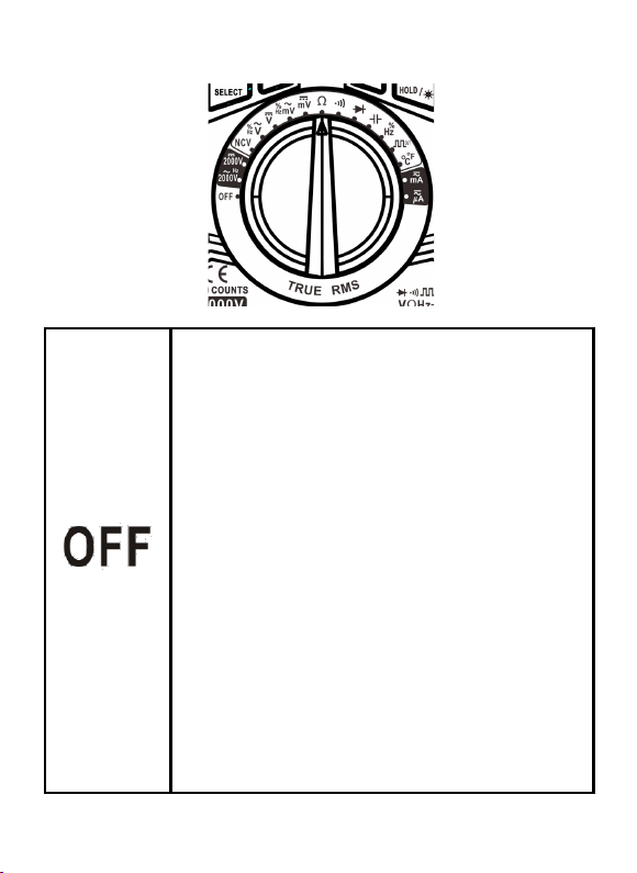
Rotary Switch
Turn off the product at this position.
• The product automatically powers
off after 15 minutes of inactivity.
• The built-in beeper beeps 5 times
1 minute before auto power off.
• To restart the product from auto
power off, press the SELECT
button or turn the rotary switch
back to the OFF position and then
to a needed position.
• To disable the Auto Power Off
function, hold down the SELECT
button when turning on the
product, you will hear four beeps if
you have successfully disabled
the function.
7
8
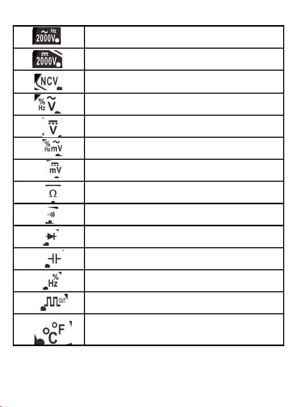
AC High Voltage:≤2000V AC
DC High Voltage:≤2000V DC
NCV: Non-contact voltage
AC Voltage:≤750V AC
DC Voltage:≤1000V DC
AC Millivolt:≤600mV AC
DC Millivolt:≤600mV DC
Resistance:≤60MΩ
Continuity
Diode
Capacitance:≤60mF
Frequency:≤10MHz
Square wave out:50Hz~5000Hz
Temperature:Celsius:-20~1000,
Fahrenheit:-4~1832
8

9
AC/DC Current Milliampere:≤600mA
AC/DC Current Microampere:≤6000uA
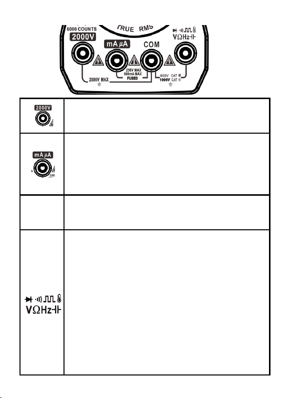
Input Terminals
2000V AC/DC high voltage
measurement dedicated input port.
AC and DC small current measurement
input port
Milliampere <600mA microampere
<6000uA
COM
Common (return) terminal for all
measurements.
Input terminal for the measurements of:
1. AC/DC voltage
2. Resistance
3. Capacitance
4. Frequency
5. Temperature
6. Continuity
7. Diode
8. Duty cycle
9. Square waves output
10

Measurements Instruction
Measure AC/DC Voltage
1. Connect the black test lead to the COM
Terminal and the red lead to the Terminal.
2. According to the voltage signal that needs to
be measured, rotate the rotating knob to select
AC or DC voltage gear; Press the RANGE key
to select AUTO or MANUAL mode. Touch the
probes to the correct test points of the circuit to
measure the voltage.
3. Read the measured voltage on the display.
Measure AC/DC Current
1. Connect the black test lead to the COM
Terminal and the red lead to the mA μ A
Terminal (The maximum test value is 600mA).
11
*Do not measure voltage that exceeds the extremes
as indicated in the Specifications.
*Do not touch high voltage circuit during
measurements.

2. The knob switch points the arrow on the knob to
the AC/DC mA or uA range according to the signal
indication.
3. Break the circuit path to be measured, connect the
test leads across the break and apply power.
4. Read the measured current on the display.
Measure Resistance
1. Connect the black test lead to the COM
Terminal and the test lead to the Terminal.
2. Turn the rotary switch to Ω mode according to
the signal instructions.
3. Touch the probes to the desired test points of
the circuit to measure the resistance.
4. Read the measured resistance on the display.
12
*Do not measure current that exceeds the extremes
as indicated in the Specifications.
*This meter has a small current range, and the
maximum current should not exceed 600mA.
Evaluate before measuring, and then select the
appropriate gear.
*Do not input voltage at this setting.
Test f or Continuity
1. Connect the black test lead to the COM
Terminal and the red lead to the Terminal.
2. Turn the rotary switch to continuity mode.
3. Touch the probes to the desired test points of
the circuit.
4. The built-in beeper will beep when the
resistance is lower than 50Ω, which indicates a
short circuit.
Test D iodes
1. Connect the black test lead to the COM
Terminal and the red lead to the Terminal.
13
*Do not input voltage at this setting.
*Disconnect circuit power and discharge all
capacitors before you test resistance.
*Do not input voltage at this setting.
2. Turn the rotary switch diode.
3. Connect the red probe to the anode side and
the black probe to the cathode side of the
diode being tested.
4. Read the forward bias voltage value on the
display.
5. If the polarity of the test leads is reversed with
diode polarity or the diode is broken, the
display reading shows “ ”.
Measure Capa citance
1. Connect the black test lead to the COM
Terminal and the red lead to the Terminal.
2. Turn the rotary switch to .
3. Connect the red probe to the anode side and
fewwfew
14
*Do not input voltage at this setting.
*Disconnect circuit power and discharge all
capacitors before you test diode.
the black probe to the cathode side of the
capacitor being tested.
4. Read the measured capacitance value on the
display once the reading is stablized.
Measure Frequency
1. Connect the black test lead to the COM
Terminal and the red lead to the Terminal.
2. Turn the rotary switch to (applies to high
frequency with low voltage); or turn the rotary
switch to AC Voltage mode, press SELECT
once to toggle to the Frequency Mode (applies
to low frequency with high voltage).
3. Touch the probes to the desired test points.
4. Read the measured frequency value on the
display.
15
*Disconnect circuit power and discharge all
capacitors before you test capacitance.
will show the room temperature, to toggle
between ℃/℉, press SELECT button.
3. Touch the probes to the desired test points.
4. Read the measured temperature on the
display.
Measure Duty Cycle
1. Connect the black test lead to the COM
Terminal and the red lead to the Terminal.
2. Turn the rotary switch to , press the
SELECT button once to toggle to the Duty
Cycle Mode .
3. Touch the probes to the desired test points.
4. Read the measured duty cycle value on the
display.
Measure Temperature
1. Connect the black thermocouple probe to the
COM Terminal and the red probe to the
Terminal.
2. Turn the rotary switch to , and the display
will
16
*Do not input voltage at this setting.

Square Wave Output
1. Connect the black test lead to the COM
Terminal and the red lead to the Terminal.
2. Turn the rotary switch to , and the default
output frequency is 50Hz. To change the output
frequency, press the SEL button.
3. Touch the probes to the desired test points.
2000V AC/DC high voltage measurement
1. According to the signal properties to be
measured, choose to turn the dial wheel to the
high voltage 2000V AC or DC voltage in the
red zone, insert the black marker into the
COM end, and insert the red plug into the
2000V end.
2. Touch the probes to the desired test points.
3. Read the measured duty cycle value on the
display.
17
*Do not input voltage at this setting.

Test NCV
1. Keep pushing the NCV button .
2. Hold the product and move it around, the built-
in beeper will beep when the inner sensor
detects AC voltage nearby. The stronger the
voltage is, the quicker the beeper beeps.
3. At this position, if the red test lead is inserted
into the , and the probe respectively
contact the neutral wire (N) and live wire (L),
can distinguish them; Strong induction for the
live wire, weak induction for the neutral wire .
18

19
Maintenance
Beyond replacing batteries and fuses, do not
attempt to repair or service the product unless you
are qualified to do so and have the relevant
calibration, performance test, and service
instructions.
Clean the Product
Wipe the product with a damp cloth and mild
detergent. Do not use abrasives or solvents. Dirt
or moisture in the terminals can affect readings.
*Remove the input signals before you clean the
product.
Replace the Batteries
When “ ” is shown on the display, batteries shall
be replaced as below:
1. Remove the test leads and turn off the
product before replacing the batteries.

20
2. Loosen the screw on the battery door and
remove the battery door.
3. Replace the used batteries with new batteries
of the same type.
4. Place the battery door back and fasten the
screw.
Replace the Fuses
When a fuse is blown or do not work properly, it
shall be replaced as below:
1. Remove the test leads and turn off the
product before replacing the fuse.
2. Loosen the four screws on the back cover and
the screw on the battery door, then remove
the battery door and the back cover.
3. Replace the fuse with a new fuse of the same
type.
4. Place the back cover and the battery door
back and fasten the screws.
Specifications
21
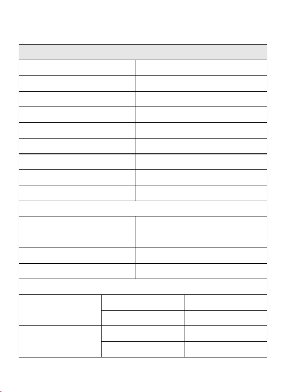
General Specifications
Display (LCD) 6000 counts
Ranging Auto/Manual
Material ABS/PVC
Update Rate 3 times/second
Ture RMS √
Data Hold √
Backlight √
Low Battery Indication √
Auto Power Off √
Mechanical Specifications
Dimension 176*91*47mm
Weight 330g(no battery)
Battery Type 1.5V AA Battery * 3
Warranty One year
Environmental Specifications
Operating
Temperature
0~40℃
Humidity
<75%
Storage
Temperature
-20~60℃
Humidity
<80%
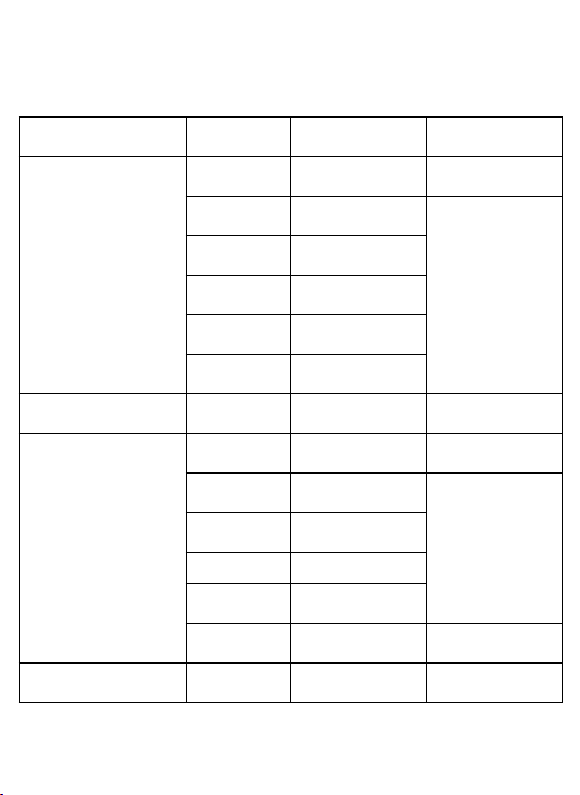
Electrical Specifications
Function Range Resolution Accuracy
DC Voltage
(V)
(mV)
60.00mV 0.01mV
600.0mV 0.1mV
±(0.5%+3)
6.000V 0.001V
60.00V 0.01V
600.0V 0.1V
1000V 1V
DC High Voltage
2000V 1V
±(2.0%+3)
AC Voltage
(V)
(mV)
60.00mV 0.01mV
600.0mV 0.1mV
±(1.0%+3)
6.000V 0.001V
60.00V 0.01V
600.0V 0.1V
750V 1V
±(1.2%+3)
DC High Voltage
2000V 1V
±(3.0%+3)
22

Function Range Resolution Accuracy
DC Current
(mA)
60.00mA 0.01mA
±(1.2%+3)
600.0mA 0.1mA
DC Current
(μA)
600.0uA 0.1uA
6000uA 1uA
AC Current
(mA)
60.00mA 0.01mA
±(1.5%+3)
600.0mA 0.1mA
AC Current
(μA)
600.0uA 0.1uA
6000uA 1uA
Resistance
600.0Ω 0.1Ω
±(0.5%+3)
6.000kΩ 0.001kΩ
60.00kΩ 0.01kΩ
600.0kΩ 0.1kΩ
6.000MΩ 0.001MΩ
60.00MΩ 0.01MΩ
±(1.5%+3)
23

Function Range Resolution Accuracy
Capacitance
6.000nF 0.001nF ±(5.0%+20)
60.00nF 0.01nF
±(2.0%+5)
600.0nF 0.1nF
6.000μF 0.001μF
60.00μF 0.01μF
600.0μF 0.1μF
6.000mF 0.001mF
±(5.0%+5)
60.00mF 0.01mF
Frequency
9.999Hz 0.001Hz
±(0.1%+5)
99.99Hz 0.01Hz
999.9Hz 0.1Hz
9.999kHz 0.001kHz
99.99kHz 0.01kHz
999.9kHz 0.1kHz
10.00MHz 0.01MHz
Duty Cycle
1%~99% 0.1% ±(0.1%+2)
24
Function Range Resolution Accuracy
Temperature
(-20~1000)℃ 1℃
±(3%+5)
(-4~1832)℉ 1℉
Diode √
Continuity √
NCV √
Square wave
output
50Hz~5000Hz
25