VERSION A0
March 31, 2025
RNG-SET-ANLX0
RPDX0ANL-SET
RNG-ANL-FUSEX0
RPDX0ANL
RNG-ANL-FUSE-COVER
RENOGY ANL Fuse
USER MANUAL
20A I 30A I 40A I 50A I 60A I 80A I 100A I 200A I 300A I 400A
Before Getting Started
The user manual provides important operation and maintenance instructions for RENOGY ANL
Fuse Set w/ Fuse, RENOGY ANL Fuse Cover, and RENOGY ANL Fuse.
Read the user manual carefully before operation and save it for future reference. Failure to
observe the instructions or precautions in the user manual can result in electrical shock, serious
injury, or death, or can damage the ANL fuse or fuse set, potentially rendering it inoperable.
z
Renogy ensures the accuracy, sufficiency, and the applicability of information in the user
manual at the time of printing due to continual product improvements that may occur.
z
Renogy assumes no responsibility or liability for personal and property losses, whether
directly and indirectly, caused by the user’s failure to install and use the product in
compliance with the user manual.
z
Renogy is not responsible or liable for any failure, damage, or injury resulting from repair
attempts by unqualified personnel, improper installation, or inappropriate operation.
z
The illustrations in the user manual are for demonstration purposes only. Details may appear
slightly different depending on product revision and market region.
z
Renogy reserves the right to change the information in the user manual without notice. For
the latest user manual, visit renogy.com.
Disclaimer
RENOGY ANL Fuse Set w/ Fuse, ANL Fuse Cover, and ANL Fuse User Manual © 2025 Renogy. All
rights reserved.
RENOGY
and
are registered trademarks of Renogy.
z
All information in the user manual is subject to copyright and other intellectual property
rights of Renogy and its licensors. The user manual may not be modified, reproduced, or
copied, in whole or in part, without the prior written permissions of Renogy and its licensors.
z
The registered trademarks in the user manual are the property of Renogy. The unauthorized
use of the trademarks is strictly prohibited.
Online Manual
User Manual

1. Safety First .................................................................................................................................... 1
1.1. Symbols Used ..........................................................................................................................................1
1.2. Important Safety Instructions .............................................................................................................1
2. General Information .....................................................................................................................2
2.1. Introduction ............................................................................................................................................ 2
2.2. Key Features .......................................................................................................................................... 2
2.3. SKU .......................................................................................................................................................... 2
3. Technical Specifications ..............................................................................................................3
3.1. Electrical Parameters ........................................................................................................................... 3
3.2. Dimensions ............................................................................................................................................4
4. Get to Know ANL Fuse ..................................................................................................................5
5. Installation ....................................................................................................................................6
5.1. Required Tools ........................................................................................................................................ 6
5.2. Inspection .............................................................................................................................................. 6
5.3. Wear Insulating Gloves ........................................................................................................................ 6
5.4. Installation Instructions ...................................................................................................................... 7
6. Components ..................................................................................................................................8
7. Functional Characteristics .......................................................................................................... 8
8. FAQ .................................................................................................................................................9
Renogy Support .............................................................................................................................. 10
Table of Contents
— 1 —
1. Safety First
Renogy accepts no liability for any damage caused by:
z
Force majeure including fire, typhoon, flood, earthquake, war, and terrorism.
z
Intentional or accidental misuse, abuse, neglect or improper maintenance, and use under
abnormal conditions.
z
Improper installation, improper operation, and malfunction of a peripheral device.
z
Contamination with hazardous substances or radiation.
z
Alterations to the product without express written consent from Renogy.
1.1. Symbols Used
The following symbols are used throughout the user manual to highlight important information.
WARNING: Indicates a potentially hazardous condition that could result in personal injury or
death.
CAUTION: Indicates a critical procedure for safe and proper installation and operation.
NOTE: Indicates an important step or tip for optimal performance.
1.2. Important Safety Instructions
z
The ANL fuses or fuse sets listed this manual shall only be deployed in DC systems operating
at lower than 72V. Installation in higher-voltage systems violates safety standards and voids
product warranties.
z
Only use ANL fuses or fuse sets with current ratings that exactly match the system’s rated
current. Never install mismatched fuses. Substitution with non-identical fuses is prohibited
under safety standards.
z
Prior to installation, verify the ANL fuse and fuse set terminals exhibit no corrosion (white/
green oxidation), pitting, or deformation. DO NOT use any damaged ANL fuses or fuse sets
showing signs of erosion or wear.
z
Verify the ANL fuse is intact with no signs of tripping, loose connections, or corrosion. DO NOT
use any fuse exhibiting these defects.
z
To guarantee your safety, wear insulating gloves during the fuse or fuse set installation.
z
Risk of electric shock! Fuse or fuse set replacement requires full power disconnection. Never
perform fuse or fuse set replacement on live circuits to eliminate shock hazards.
z
Inspect and clean all fuse terminals and contact surfaces thoroughly before installation to
ensure proper contact alignment.
z
Handle fuses or fuse sets with care to avoid impact/dropping during installation. Never
install damaged fuses that may cause premature tripping at rated current and other thermal
runaway risks.
z
Inspect and verify the ANL fuse and set terminals exhibit no corrosion (white/green oxidation),
pitting, or deformation regularly.
z
Always replace blown ANL fuses or fuse sets with identical models. Never use substitutes like
copper wires to prevent hazardous failures.
z
Troubleshooting your system is required before fuse or fuse set replacement. Use a
multimeter to verify overload conditions or short-circuit faults.
— 2 —
2. General Information
2.1. Introduction
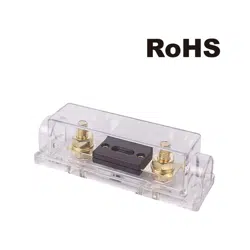
A RENOGY ANL Fuse Set w/ Fuse contains a Renogy ANL fuse and an ANL Fuse Cover. The fuse
set offers complete protection to your system, protects your charge controller, battery, inverter,
and connecting wires from over-current, and ensures you get the longevity out of your system
as expected. The ANL fuse is composed of high-quality alloy and brass copper materials and the
clear protective non-conductive resistant cover is ideal for custom installation.
2.2. Key Features
z
Safeguard Your System
Ignition protection guarantees the safe use of the fuse in RVs, boats, or any other closed
environments.
z
Multiple Specifications are Available
Offers multiple specifications of the ANL fuses to meet the requirement of different size
systems. Optional specifications including 20A/30A/40A/60A/80A/100A/200A/300A/400A.
The protective cover is compatible with all specifications.
z
High Quality and Easy to Use Design
The ANL fuse is composed of high-quality alloy and brass copper materials and works with a
clear protective non-conductive resistant cover which is ideal for custom installation and can
be easily added to your solar system.
z
Environment Friendly
The ANL fuse is RoHS compliant, which confirms that it’s free from environmentally
hazardous, difficult-to-dispose substances.
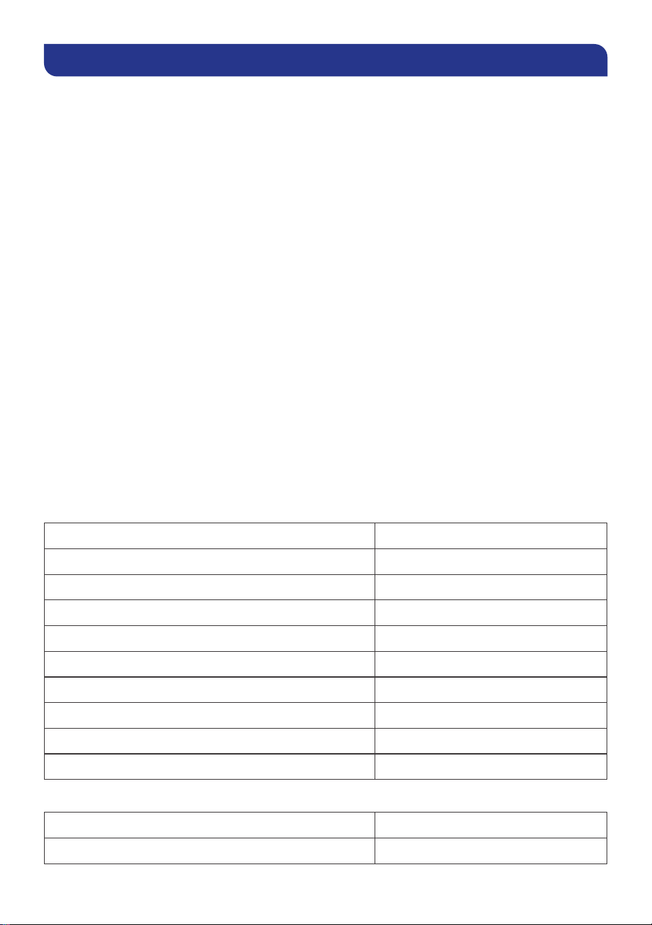
2.3. SKU
A Renogy ANL Fuse Set includes one ANL fuse and fuse cover. For stocked sets, you may replace
blown fuses or covers separately. Refer to the tables below for the specific model number.
█
ANL Fuse Set w/ Fuse
20A ANL Fuse Set w/ Fuse RNG-SET-ANL20
30A ANL Fuse Set w/ Fuse RNG-SET-ANL30
40A ANL Fuse Set w/ Fuse RNG-SET-ANL40
50A ANL Fuse Set w/ Fuse RPD50ANL-SET
60A ANL Fuse Set w/ Fuse RNG-SET-ANL60
80A ANL Fuse Set w/ Fuse RPD80ANL-SET
100A ANL Fuse Set w/ Fuse RNG-SET-ANL100
200A ANL Fuse Set w/ Fuse RPD200ANL-SET
300A ANL Fuse Set w/ Fuse RPD300ANL-SET
400A ANL Fuse Set w/ Fuse RPD400ANL-SET
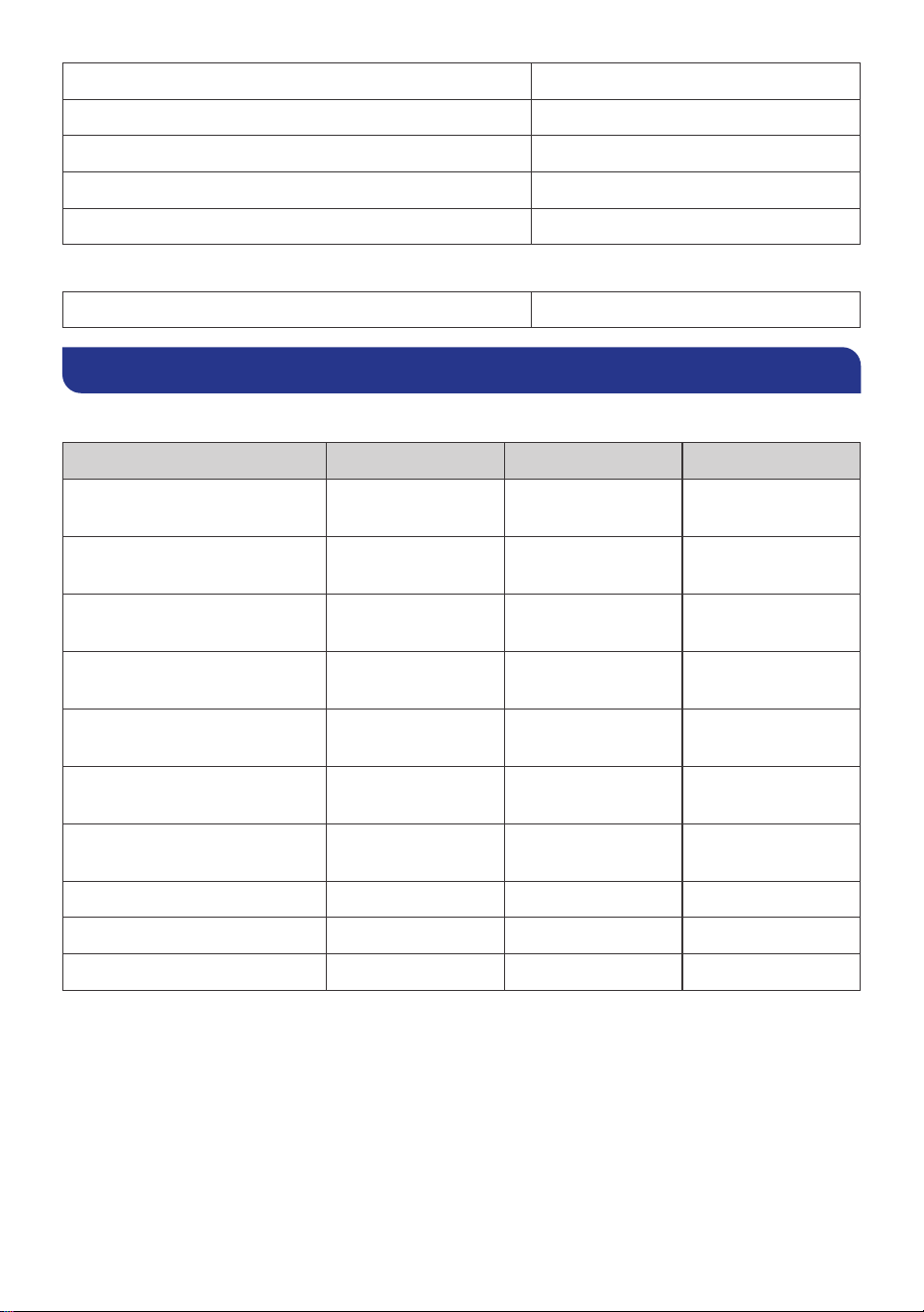
█
ANL Fuse
20A ANL Fuse RNG-ANL-FUSE20
30A ANL Fuse RNG-ANL-FUSE30
— 3 —
40A ANL Fuse RNG-ANL-FUSE40
50A ANL Fuse RPD50ANL
60A ANL Fuse RNG-ANL-FUSE60
80A ANL Fuse RPD80ANL
100A ANL Fuse RNG-ANL-FUSE100
█
ANL Fuse Cover
ANL Fuse Cover RNG-ANL-FUSE-COVER
3. Technical Specifications
3.1. Electrical Parameters
Product Current Rating Voltage Rating Interrupt Capacity
RNG-SET-ANL20
RNG-ANL-FUSE20
≤ 20A ≤ 72V 40A
RNG-SET-ANL30
RNG-ANL-FUSE30
≤ 30A ≤ 72V 60A
RNG-SET-ANL40
RNG-ANL-FUSE40
≤ 40A ≤ 72V 80A
RPD50ANL-SET
RPD50ANL
≤ 50A ≤ 72V 100A
RNG-SET-ANL60
RNG-ANL-FUSE60
≤ 60A ≤ 72V 120A
RPD80ANL-SET
RPD80ANL
≤ 80A ≤ 72V 160A
RNG-SET-ANL100
RNG-ANL-FUSE100
≤ 100A ≤ 72V 200A
RPD200ANL-SET ≤ 200A ≤ 72V 400A
RPD300ANL-SET ≤ 300A ≤ 72V 600A
RPD400ANL-SET ≤ 400A ≤ 72V 800A
— 4 —
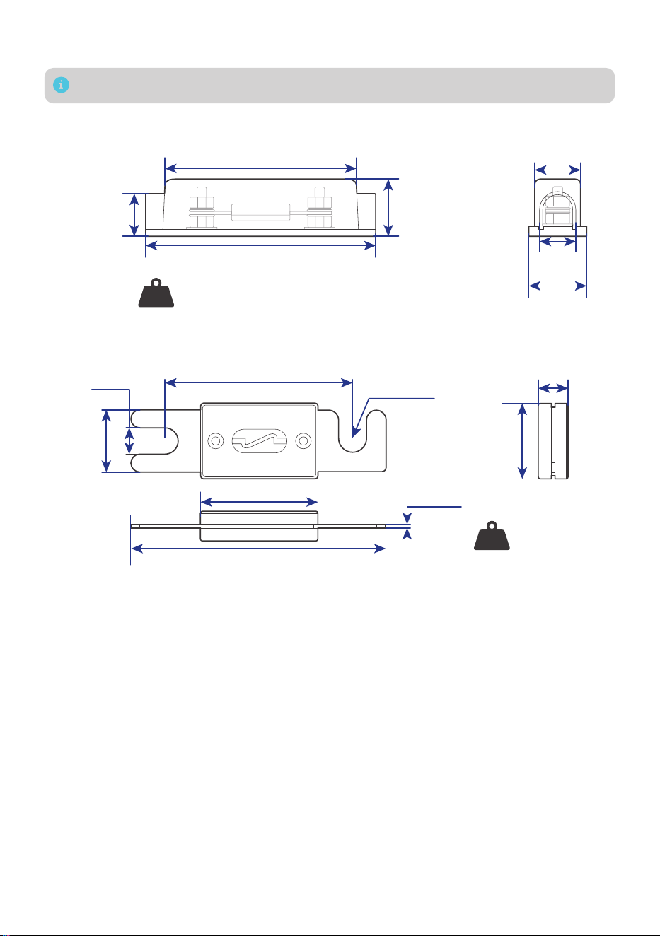
3.2. Dimensions
Dimension tolerance: ±0.2 in (0.5 mm)
█
ANL Fuse Set w/ Fuse & ANL Fuse Cover
4.88 in (124 mm)
1.48 in
(37.6 mm)
0.93 in
(23.7 mm)
1.17 in
(29.8 mm)
1.15 in
(29.2 mm)
1.48 in
(37.5 mm)
4.02 in (102 mm)
ANL Fuse Set w/ Fuse Weight: 1.54 gr / 0.1 g
ANL Fuse Cover Weight: 1.23 gr / 0.08 g
Weight
█
ANL Fuse
2.36 in (60 mm)
R 0.16 in
(R 4 mm)
0.33 in
(8.4 mm)
0.75 in
(19 mm)
1.42 in (36 mm)
3.15 in (80 mm)
0.03 in
(0.8 mm)
0.35 in
(9 mm)
0.91 in
(23 mm)
0.31 gr / 0.02 g
Weight
— 5 —
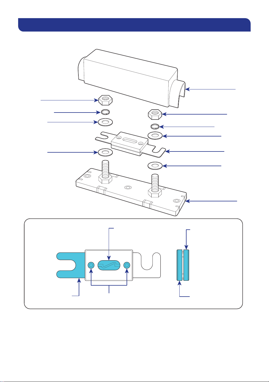
4. Get to Know ANL Fuse
This manual takes an ANL Fuse Set w/ Fuse as an example. A Renogy ANL Fuse Set includes one
ANL fuse and fuse cover.
Cover
Nut (M8)
Nut (M8)
Spring Washer
Flat Washer
Flat Washer
Spring Washer
Flat Washer
Flat Washer
Base
*ANL Fuse
*ANL Fuse
Terminal Contact
Material: Alloy
Connector
Material: Brass Copper
Plastic Cover
Material: Bakelite
Plastic Base
Material: Bakelite
Transparent Cover
Material: IS-3PC
— 6 —
5. Installation
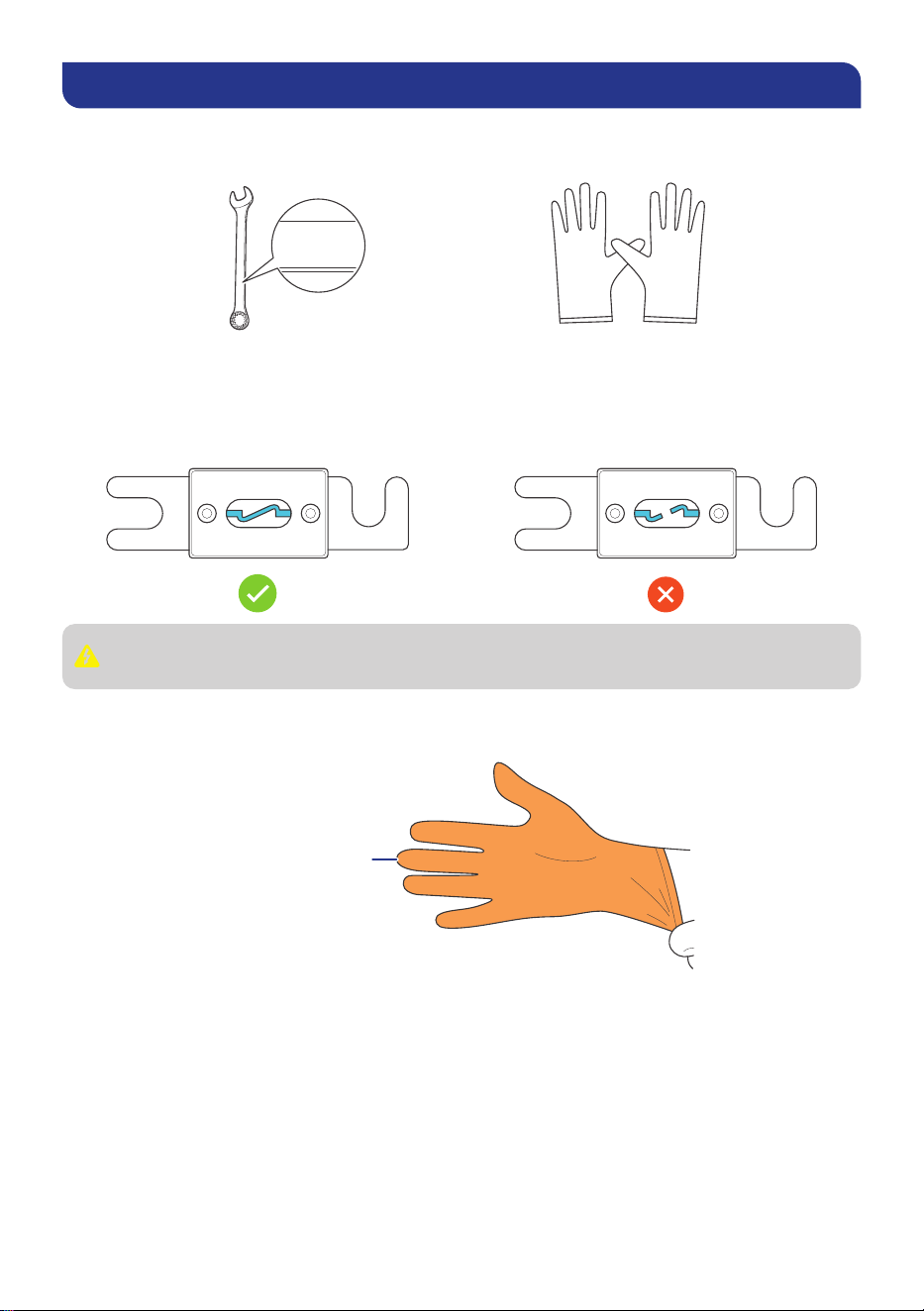
5.1. Required Tools
Prior to installing and configuring the ANL fuse, prepare the recommended tools.
Insulating Gloves
Wrench (17/32 in)
13 mm
13 mm
13 mm
5.2. Inspection
Prior to installation, verify ANL fuse and set terminals exhibit no corrosion (white/green oxidation),
pitting, or deformation. Verify the ANL fuse is intact with no signs of tripping, loose connections,
or corrosion. DO NOT use any fuse or fuse set exhibiting these defects.
Inspect and verify the ANL fuse and set terminals exhibit no corrosion (white/green
oxidation), pitting, or deformation regularly.
5.3. Wear Insulating Gloves
To guarantee your safety, wear insulating gloves during the fuse installation.
Insulating Gloves
— 7 —
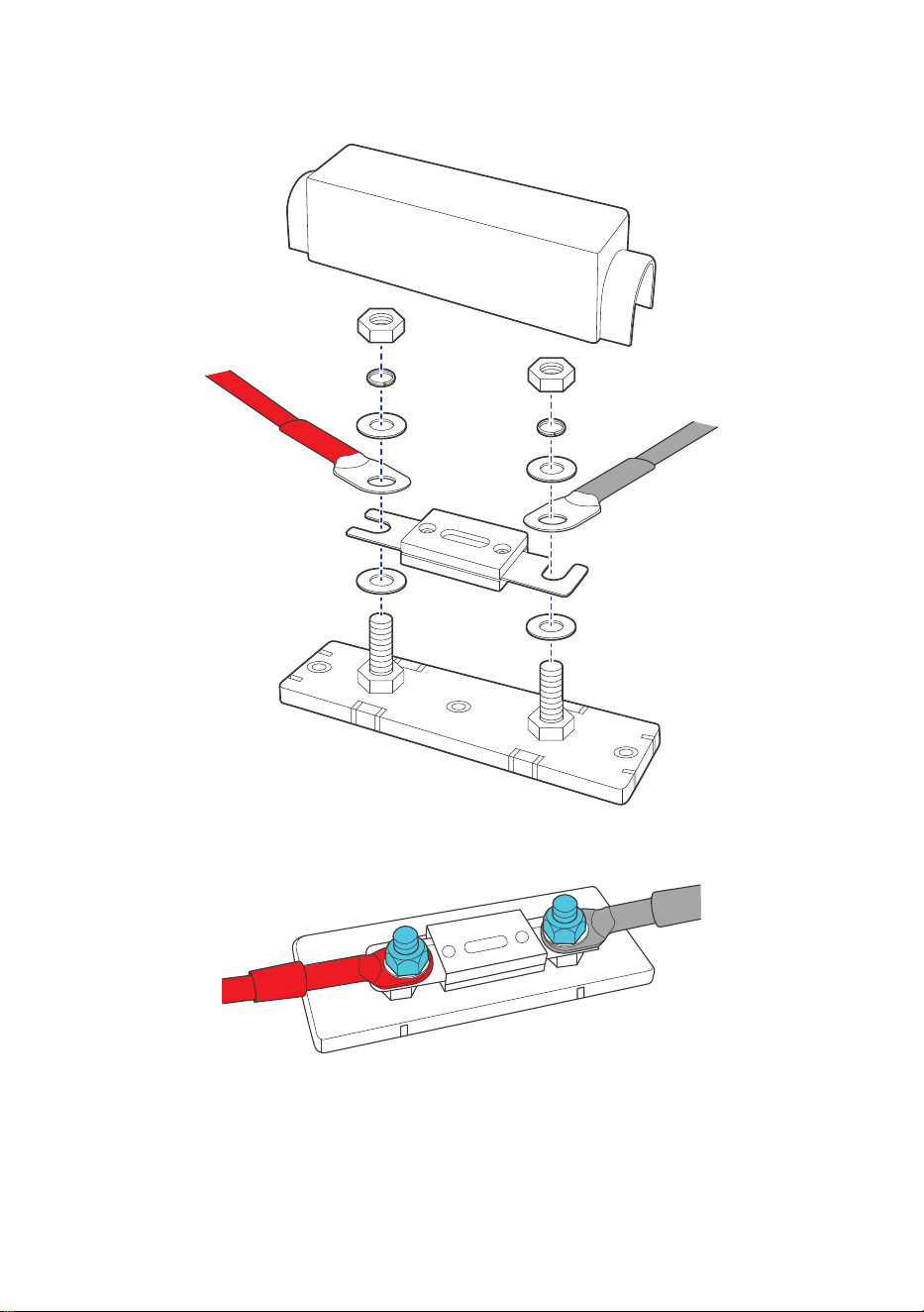
5.4. Installation Instructions
Install all components in the exact order shown in the illustration below. Ring terminals sized for
M8 studs (M8-M10 acceptable).
Tighten the nuts to 70.8 in•lbs (8 N•m).
70.8 in·lbs
(8 N·m)
— 8 —
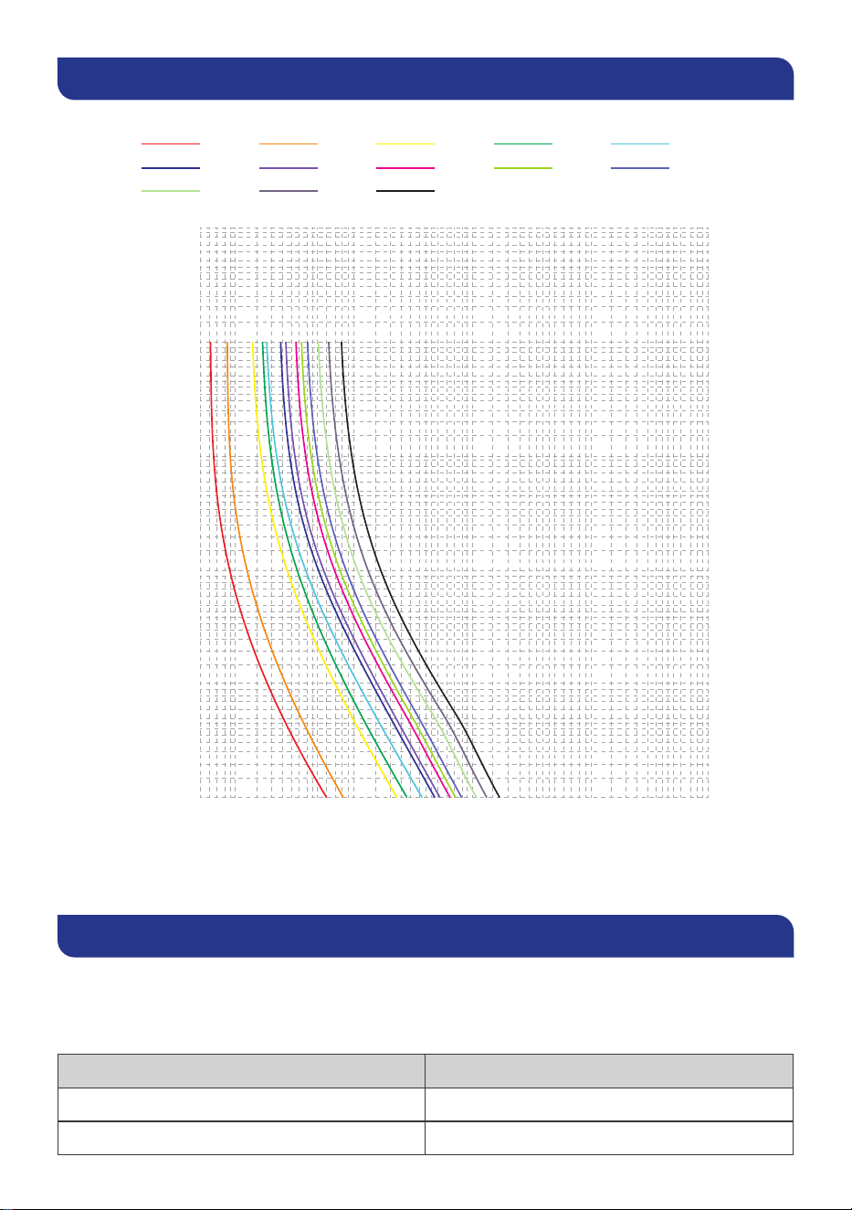
6. Components
Time-current curves – average melt:
50
.01
.02
.03
.05
.07
.1
.2
.3
.5
.7
1
2
3
5
7
10
20
30
50
70
100
200
300
500
700
1000
70
100
200
300
500
700
1000
2000
3000
5000
7000
10000
20000
30000
50000
70000
100000
200000
300000
500000
700000
1000000
Time (Seconds)
Current (Ampere)
35A
150A
50A
175A
80A
200A
100A
250A
125A
275A
300A
350A
400A
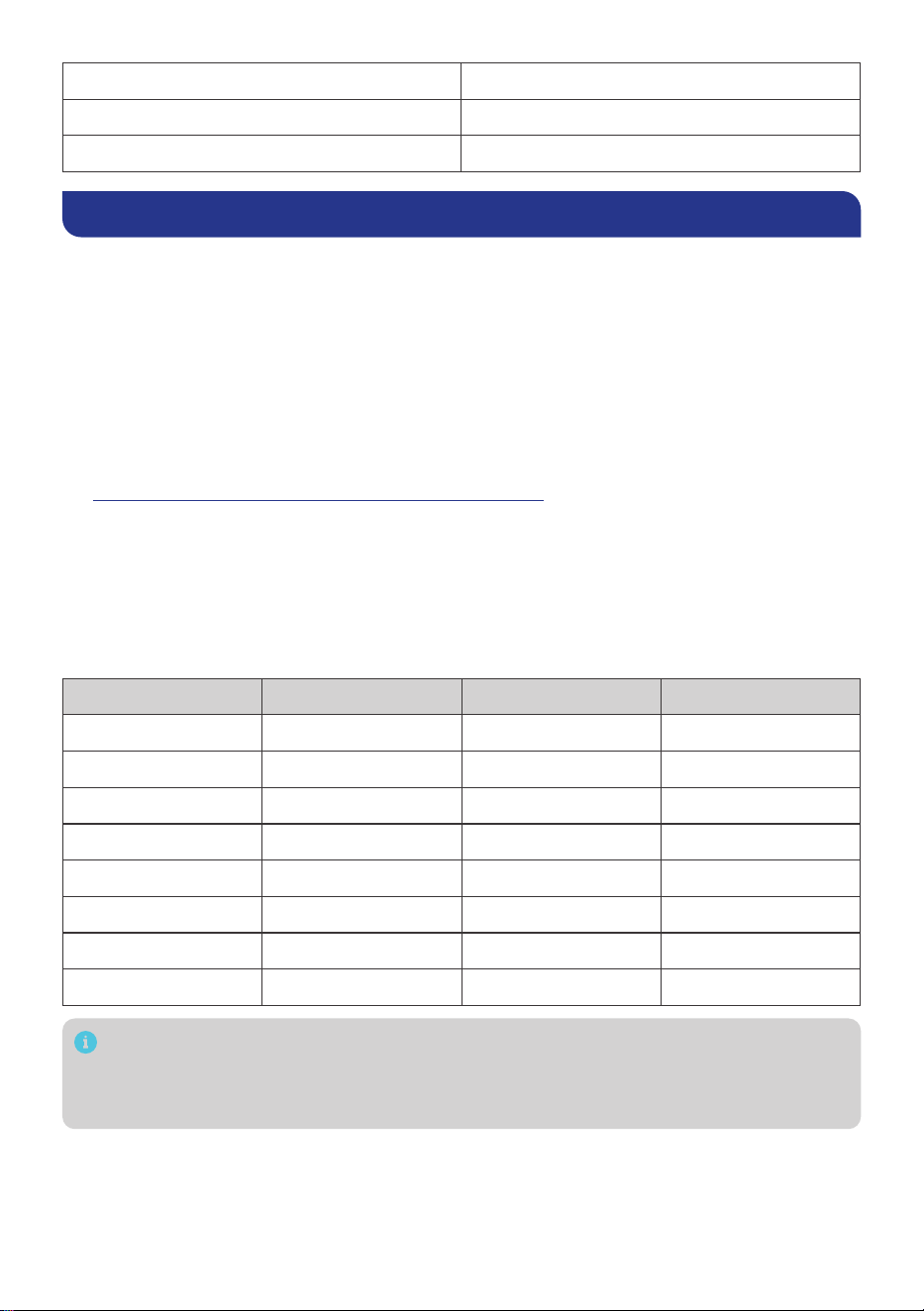
7. Functional Characteristics
A fuse does not blow when the current reaches its rated current. It is designed to pass its rated
current without opening. A fuse will take varying times to blow under different conditions. A fuse
will pass significantly more than its rated current for a very short time. The time periods for other
fuses will be slightly different.
Testing Current (% of amp rating) Blow Time Limit
150% (Rating < 225A) 1 hour at minimum
160% (Rating > 225A) 6 seconds at minimum
— 9 —
220% 60 seconds at maximum
250% 0.8s to 10s
400% 0.2s to 2s
8. FAQ
█
Can the fuse be replaced individually, or does the entire fuse set require replacement?
The fuse alone is replaceable (no full device replacement needed). Replace the fuse set only
when the fuse holder/terminals are damaged.
█
What size are the posts on this fuse set holder?
The posts are 5/16“ studs (metric equivalent: M8). Ring lugs sized for M8-M10 are
recommended.
█
How do you size an ANL fuse?
Always prioritize the recommended fuse size in the manual of your charge controller, battery
charger, or inverter.
Alternatively, you can size a fuse based on the current going through the fuse. For details, see
Size Fuses or Circuit Breakers for a Solar Power System at Renogy Learning Center.
█
Does the fuse or fuse set come with a fuse cable?
No. You need to purchase a fuse cable separately.
█
How to size a fuse cable for the ANL fuse or fuse set?
Always prioritize the recommended cable size in the manual of your charge controller, battery
charger, or inverter. Alternatively, you can refer to the table below for copper cable ampacities
with different gauge sizes for up to 13 feet (4 m) cables. Cables longer than 13 feet (4 m) may
require thicker gauge wires to prevent excessive voltage drop in undersized wiring.
Cable Gauge Size Ampacity Cable Gauge Size Ampacity
14 AWG (2.08 mm²) 25A 1 AWG (42.41 mm²) 145A
12 AWG (3.33 mm²) 30A 1/0 AWG (53.49 mm²) 170A
10 AWG (5.26 mm²) 40A 2/0 AWG (67.43 mm²) 195A
8 AWG (8.37 mm²) 55A 3/0 AWG (85.01 mm²) 225A
6 AWG (13.3 mm²) 75A 4/0 AWG (107.22 mm²) 260A
4 AWG (21.15 mm²) 95A 300 kcmil (152.1 mm²) 320A
3 AWG (26.67 mm²) 115A 400 kcmil (202.8 mm²) 380A
2 AWG (33.62 mm²) 130A 500 kcmil (253.5 mm²) 430A
The above values are from the NEC Table 310.16 for copper cables rated at 194°F (90°C),
operating at an ambient temperature of no more than 86°F (30°C). Please note that wire
gauge standards may vary due to factors such as temperature and installation conditions.
In actual applications, it is recommended to refer to the latest NEC standards.
— 10 —
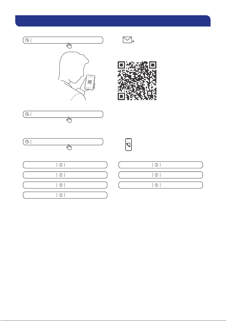
Renogy Support
To discuss inaccuracies or omissions in this quick guide or user manual, visit or contact us at:
renogy.com/support/downloads
contentservice@renogy.com
Questionnaire Investigation
To explore more possibilities of solar systems, visit Renogy Learning Center at:
renogy.com/learning-center
For technical questions about your product in the U.S., contact the Renogy technical support
team through:
renogy.com/contact-us
1(909)2877111
For technical support outside the U.S., visit the local website below:
Canada ca.renogy.com China www.renogy.cn
Australia au.renogy.com Japan jp.renogy.com
Other Europe eu.renogy.com Germany
de.renogy.com
United Kingdom
uk.renogy.com
Renogy aims to empower people around the world through education and distribution of
DIY-friendly renewable energy solutions.
Renogy Power Plus allows you to stay in the loop with upcoming solar energy innovations,
share your experiences with your solar energy journey, and connect with like-minded
people who are changing the world in the Renogy Power Plus community.
We intend to be a driving force for sustainable living and energy independence.
In support of this eort, our range of solar products makes it possible for you to minimize
your carbon footprint by reducing the need for grid power.
Renogy Empowered
Live Sustainably with Renogy
Did you know? In a given month, a 1 kW solar energy system will...
Save 170 pounds of coal from being burned
Save 300 pounds of CO2 from being released into the atmosphere
Save 105 gallons of water from being consumed
@RenogySolar @Renogy@renogyocial
Renogy Power
PLUS
Renogy reserves the right to change the contents of this manual without notice.
eVatmaster Consulting GmbH
Rodgau, Hessen, Germany
Raiffeisen Street2 B11, 63110
EC REP
Manufacturer: RENOGY New Energy Co.,Ltd
Address: No.66, East Ningbo Road Room 624-625 Taicang German
Overseas Students Pioneer Park JiangSu 215000 CN
EVATOST CONSULTING LTD
London, United Kingdom, EC2R 8AY
Office 101 32 Threadneedle Street,
UK REP
