Version A4
March 17, 2025
Renogy
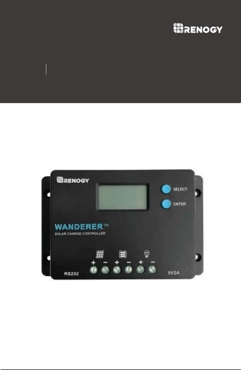
WANDERER
PWM Solar Charge Controller
10A 12V/24V
RNG-CTRL-WND10-G1
01
General Safety Information
Charge Controller Safety
This manual contains important safety, installation, and
operating instructions for the charge controller. The following
symbols are used throughout the manual:
There are no serviceable parts for this controller. Do NOT
disassemble or attempt to repair the controller.
Make sure all connections going into and from the controller
are tight. There may be sparks when making connections,
therefore, make sure there are not flammable materials or
gases near installation.
NEVER connect the solar panel array to the controller
without a battery. Battery must be connected first. This may
cause a dangerous occurrence where the controller would
experience a high open circuit voltage at the terminals.
Ensure input voltage does not exceed 50 VDC to prevent
permanent damage. Use the Open Circuit (Voc) to make
sure the voltage does not exceed this value when connecting
panels together in series.
Read all of the instructions and cautions in the manual before
beginning the installation.
Important Safety Instructions
Please save these instructions.
Indicates a potentially dangerous condition. Use
extreme caution when performing this task.
Indicates a critical procedure for safe and proper
operation of the controller
Indicates a procedure or function that is important
to the safe and proper operation of the controller.
NOTE
CAUTION
WARNING

02
Battery Safety
The charge controller should be installed indoors in a
well-ventilated, cool, and dry environment.
Do NOT let the positive (+) and negative (-) terminals of the
battery touch each other.
Use only sealed lead-acid, flooded, gel or lithium batteries
which must be deep cycle.
Explosive battery gases may be present while charging. Be
certain there is enough ventilation to release the gases.
Be careful when working with large lead acid batteries. Wear
eye protection and have fresh water available in case there is
contact with the battery acid.
Over-charging and excessive gas precipitation may damage
the battery plates and activate material shedding on them.
Too high of an equalizing charge or too long of one may
cause damage. Please carefully review the specific
requirements of the battery used in the system.
Equalization is carried out only for non-sealed / vented /
flooded / wet cell lead acid batteries.
Do NOT equalize VRLA type AGM / GEL / LITHIUM batteries
UNLESS permitted by battery manufacturer.
Do NOT allow water to enter the controller.

03
Table of Contents
General Information 04
Product Overview
05
05
06
Identification of Parts
Dimensions
Main Display
14
Auto Recognition
14
LCD Overview
15
Mounting Recommendations
07
Wiring and Fusing
08
Set the Battery type
18
Error Codes
22
Load Terminal
20
Installation
07
Operation
14
PWM Technology
16
Settings
18
Troubleshooting
22
Maintenance
24
Technical Specifications
25

04
General Information
The Wanderer is an advanced charge controller for off-grid
solar applications. Integrating highly efficient PWM charging,
this controller increases battery life and improves system
performance. It can be used for 12V/24V battery banks. The
controller is embedded with self-diagnostics and electronic
protection functions that prevent damages from installation
mistakes or system faults.
Key Features
Automatic Voltage Detection for 12V/24V Non-Lithium
Systems and Lithium Battery Activation
Preset for Deep Cycle Sealed, Gel, Flooded Batteries and
Lithium-iron Phosphate Batteries
4-Stage PWM Charging: Bulk, Boost, Float, and Equalization
Back-lit LCD for displaying system operation, diverse load
control, and error codes if any
Integrated 5V, up to 2Amp USB for mobile or portable device
charging
Protection Against: overcharging, over-current, short
circuit, reverse polarity
05
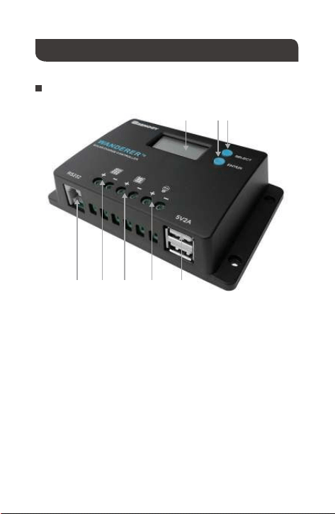
Product Overview
Identification of Parts
①②③
④⑤⑥⑦⑧
Key Parts
LCD Screen
Select Button
Enter Button
USB Ports
Load Terminals
Battery Terminals
PV Terminals
RS232 Communication Port (reserved)
①
②
③
④
⑤
⑥
⑦
⑧
06
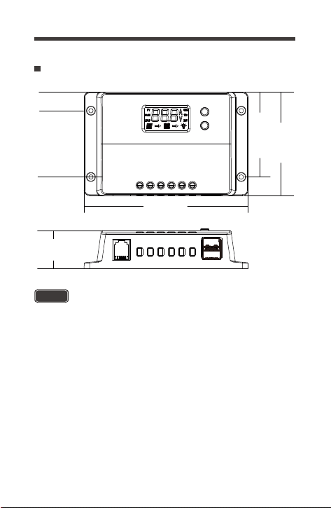
Dimensions
NOTE
The dimensions have a ±0.5mm tolerance
[2.421in]
61.50mm
[2.953in]
75mm
[0.531in]
13.50mm
[0.063in]
R1.60mm
[1.083in]
27.50mm
[4.685in]
119mm

07
Refer to the technical specifications for max wire sizes on the
controller and for the maximum amperage going through wires.
Do not over-torque or over tighten the screw terminals. This
could potentially break the piece that holds the wire to the
charge controller.
CAUTION
Installation
Connect the battery to the charge controller BEFORE
connecting the solar panel(s) unless you have the solar
suitcase with controller exception. The controller needs a stable
power source to operate.
WARNING
Never install the controller in a sealed enclosure with flooded
batteries. Gas can accumulate and there is a risk of explosion.
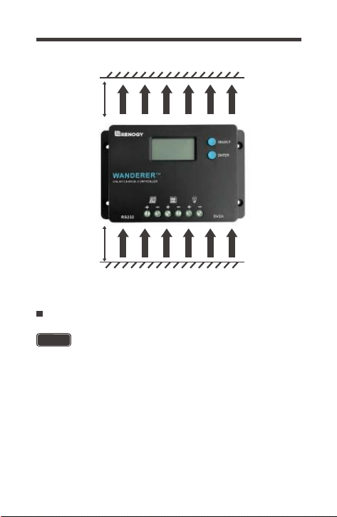
1. Choose Mounting Location—place the controller on a
vertical surface protected from direct sunlight, high tempera-
tures, and water. Make sure there is good ventilation.
2. Check for Clearance—verify that there is sufficient room to run
wires, as well as clearance above and below the controller for
ventilation. The clearance should be at least 6 inches (150mm).
WARNING
3. Mark Holes
4. Drill Holes
5. Secure the charge controller.
Mounting Recommendations
08
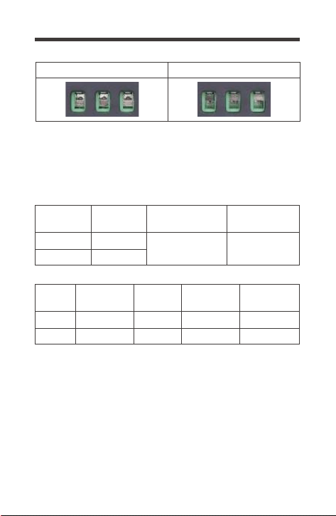
Use bare wiring when connecting to the Wanderer’s terminal
blocks. Due to default positioning, you must ensure that the
terminal hatch is completely open before the first-time use.
1.Make sure to rotate the hatch counterclockwise (CCW) into
the open position to expose the wire hatch
3.Rotate clockwise (CW) to until the hatch has closed and
clamped onto the wire
2.Insert bare wire into the terminal for the respective connection
6 inches
warm air
(150mm)
cool air
6 inches
(150mm)
Wiring and Fusing
NOTE
The wire terminals are closed by default.
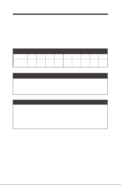
Depending on the PV Array wiring and battery size, the
recommended fuse and cable gauge will depend on the actual
amps flowing through the cable. The following chart accounts for
less than 3% voltage drop and may not account for all configura-
tions.
*Panel connection assumes series to meet 24V system
minimum setup.
Larger wire sizes generally improve performance, whereas
smaller wire sizes may reduce performance, especially if
undersized. When considering wiring, fusing, and connection
options, think big and short as possible as heavier components
and shorter wire length offer less resistance and voltage drop.
Terminal Size Limitations may apply.
09
Closed Terminal BlockOpen Terminal Block
PV Watts
Battery
Voltage
Battery Cable
Recommended
Max
Terminal Size
12V 130W
24V 260W
12 AWG 12 AWG
PV Input
Amps
Battery
Voltage
0 ~ 10ft /
0 ~ 3m
11 ~ 20ft /
3m ~ 6m
12V 100W ~ 5A
24V 2x100W~5A*
16 AWG
16 AWG
16 ~ 14AWG
16 ~ 14AWG
21 ~ 30ft /
6m ~ 9m
14 ~ 12AWG
14 ~ 12AWG
10
2 0
170A
Fusing is a recommendation in PV systems to provide a safety
measure for connections going from panel to controller and
controller to battery. Remember to always use the
recommended wire gauge size based on the PV system and
the controller.
AWG 16 14 12 10 8 6 4
Max.
Current
55A30A20A15A10A
75A 95A 130A
NEC Maximum Current for different Copper Wire Sizes
Parallel
Fuse from Controller to Battery
Fuse from Solar Panel(s) to Controller
Ex. 200W; 2 X 100 W panels
Ex. Wanderer 10 = 10A fuse from Controller to Battery
Controller to Battery Fuse =
Current Rating of Charge Controller
Fuse = minimum of 11.5 * 1.2 = 14.38= 15A fuse
Total Amperage = Isc1 + Isc2 = (5.75A + 5.75A) * 1.2
11
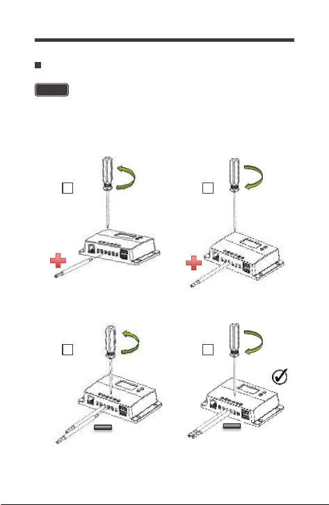
Battery Wiring
WARNING
Connect the battery to the charge controller BEFORE
connecting the solar panel(s) unless you have the solar suitcase
with controller exception. The controller needs a stable power
source to operate.
1
counterclockwise
2
3
counterclockwise
4
clockwise
clockwise
12
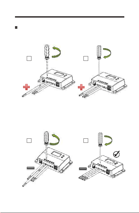
PV Wiring
1
counterclockwise
2
3
counterclockwise
4
clockwise
clockwise
13
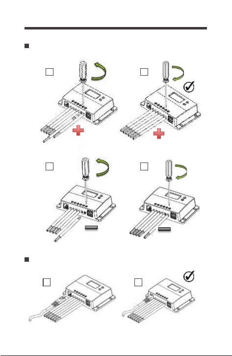
Load Wiring (Optional)
Communication Wiring (Optional)
1 2
1
counterclockwise
2
3
counterclockwise
4
clockwise
clockwise
14
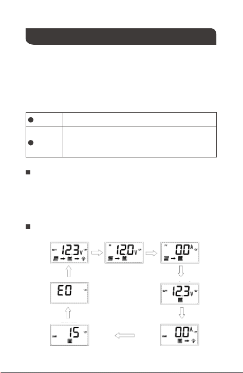
After connecting the battery to the charge controller, the
controller will turn on automatically. Assuming normal
operation, the charge controller will cycle through different
displays. The user can adjust some parameters based on the
display screen. The user can manually cycle through the
display screens by using the “SELECT” and “ENTER” buttons.
The Wanderer controller will be able to automatically detect the
battery voltage for Non-Lithium 12V or 24V batteries. Lithium
batteries need to be manually programzmed and can be found
in Settings.
Operation
SELECT
ENTER
Tap—Cycles Forward through the LCD screens
Tap—Cycle Backward through the LCD Screens
Long Press—Hold to enter Setting Mode
Tap—Turns on Load Circuit in Manual Load Mode
Load Current
Load Mode
Error Code
Main Screen Solar Panel Voltage Charging Current
Battery Voltage
Auto Recognition
Main Display
15
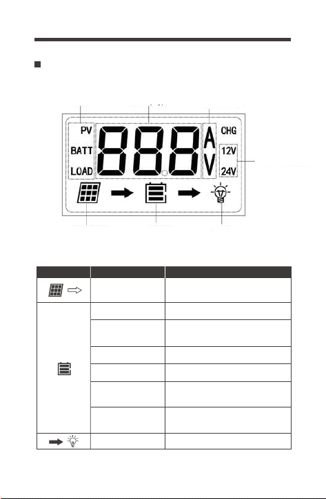
LCD Overview
Icon or Value State Description
Steady on
3 Bars Flashing
3 Bars
2 Bars
1 Bar
No Bars
Steady on
Solar Panels Charging
Battery
Battery Voltage (16.1V+)
Battery Voltage
(12.9V- 16.0V)
Battery Voltage (12.5-12.8V)
Battery Voltage (11.6-12.4V)
Battery Voltage
(11.5V and below)
Battery Voltage
(10.9V and below)
Load is On
No Bars
Flashing
Parameter Value
Port Battery type Amps/Volts
System
Voltage
LoadBatterySolar Panel
16
The Wanderer utilizes Pulse Width Modulation (PWM)
technology for battery charging. Battery charging is a current
based process so controlling the current will control the battery
voltage. For the most accurate return of capacity, and for the
prevention of excessive gassing pressure, the battery is
required to be controlled by specified voltage regulation set
points for Absorption, Float, and Equalization charging stages.
The charge controller uses automatic duty cycle conversion,
creating pulses of current to charge the battery.
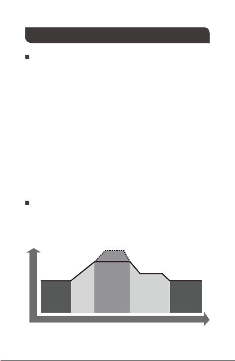
The Wanderer has a 4-stage battery charging algorithm for a
rapid, efficient, and safe battery charging. They include: Bulk
Charge, Boost Charge, Float Charge, and Equalization.
TIME
NIGHT
BOOST
EQUALIZE
FLOAT
NIGHT
BULK
CHARGE
VOLTAGE
PMM Technology
PWM Technology
Four Charging Stages
The duty cycle is proportional to the difference between the
sensed battery voltage and the specified voltage regulation set
point. Once the battery reached the specified voltage range,
pulse current charging mode allows the battery to react and
allows for an acceptable rate of charge for the battery level.

17
Bulk Charge: This algorithm is used for day to day charging. It
uses 100% of available solar power to recharge the battery and
is equivalent to constant current.
When the battery has charged to the Boost
voltage set-point, it undergoes an absorption stage which is
equivalent to constant voltage regulation to prevent heating and
excessive gassing in the battery. The Boost time is 120
minutes.
Float Charge: After Boost Charge, the controller will reduce
the battery voltage to a float voltage set point. Once the battery
is fully charged, there will be no more chemical reactions and all
the charge current would turn into heat or gas.Because of this,
the charge controller will reduce the voltage charge to smaller
quantity, while lightly charging the battery. The purpose for this
is to offset the power consumption while maintaining a full
battery storage capacity.
Boost Charge:
In the event that a load drawn from the battery exceeds the
charge current, the controller will no longer be able to maintain
the battery to a Float set point and the controller will end the float
charge stage and refer back to bulk charging.
Equalization:
Is carried out every 28 days of the month. It is
intentional overcharging of the battery for a controlled period.
Certain types of batteries benefit from periodic equalizing
charge, which can stir the electrolyte, balance battery voltage
and complete chemical reaction. Equalizing charge increases
the battery voltage, higher than the standard complement
voltage, which gasifies the battery electrolyte.
Once equalization is active in the battery charging, it will not exit
this stage unless there is adequate charging current from the
solar panel. There should be NO load on the batteries when in
equalization charging stage.
WARNING

18
Set the Battery type
The Wanderer PWM charge controller has a reactivation feature
to awaken a sleeping lithium battery. The protection circuit of
Li-ion battery will typically turn the battery off and make it
unusable if over-discharged. This can happen when storing a
Li-ion pack in a discharged state for any length of time as
self-discharge would gradually deplete the remaining charge.
Without the wake-up feature to activate and charge batteries,
these batteries would become unserviceable and the packs
would be discarded. The Wanderer will apply a small charge
current to activate the protection circuit and if a correct cell
voltage can be reached, it starts a normal charge.
Over-charging and excessive gas precipitation may damage the
battery plates and activate material shedding on them. Too high
of equalizing charge or for too long may cause damage. Please
carefully review the specific requirements of the battery used in
the system.
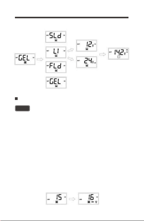
At minimum you should set the battery type and voltage to
ensure your system’s livelihood.
1.Highlight Battery Voltage Screen
2.Hold ENTER for approximately 3s until the battery type starts
to flash
3.Tap SELECT to highlight your desired battery
4.To confirm, hold ENTER for 3s to select the battery
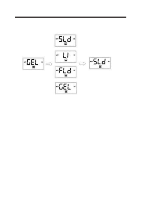
Set the battery type by maneuvering to the Battery Voltage
Screen where it should demonstrate the battery icon and voltage.
Lithium Battery Activation
Settings
Non-Lithium
19
Press SELECT until you highlight the Battery Voltage Screen
where it should demonstrate the battery icon and voltage.
Lithium
1.Highlight Battery Voltage Screen
2.Hold ENTER for approximately 3s until the battery type starts
to flash
3.Tap SELECT to highlight Lithium battery, Tap ENTER to
confirm Lithium
4.Tap SELECT to highlight nominal battery voltage as 12V or
24V, Tap Enter to confirm
5.Tap Select to choose your charging voltage setpoint, voltages
are in 0.2V increments
6.To confirm, hold ENTER for 3s to confirm Lithium, Battery
Voltage, and Charge Voltage
Battery Type
20
Load Terminal
Programming the Load Terminal
Battery Type
System Voltage
Make sure the load is compatible with the battery type
of the system. 12V loads damaged in 24V battery
systems will not be covered in warranty.
The Load Terminal allows you to connect DC devices directly to
the controller with timer functions as optional features. The Load
Terminal is an extension of your battery charging circuit so the
voltages on your battery will be present in the Load terminal
since it is powered by the battery. This means that when
charging a 12V bank, those charging voltages will also be seen
in the Load Terminal. The terminal limits are set by the controller,
so no more than 10Amps. In addition, when connecting to a 24V
battery bank, you will also have a 24V DC Load Terminal that you
can also utilize. Stick with simple electronics such as lights, fans,
that have no issues turning on/off at any time.
WARNING

21
Press SELECT until you highlight the Load Mode Screen where
it should demonstrate a numerical load mode. The following chart
indicates numbers representing hours ON that the load terminal
Programs 0, 1-14, 16, and 17 are automatic processes that
operate from the PV detection circuit as soon as they are set.
No other action is necessary. Program 15 requires manual user
toggling so users will need to press ENTER on the Main Screen
or Load Mode Screen to observe the Light Bulb Brightness icon
being activated to confirm Load also being activated.
Manual
Test
24Hr
In this mode, the user can turn the
Load On/Off by pressing the Enter
button at any time.
The load will be on for 24 hours a day.
Used to troubleshoot load terminal
(No Time Delay). When voltage is
detected load will be off and when no
voltage is detected load will be on.
15
16
17
Time
control
The load will turn on at night when the
solar panel is no longer producing
any power after a short time delay.
The load will turn off when the panel
starts producing power.
When the panel is no longer
producing power, the load will be ON
for 1-14 hours or until the panel starts
producing power.
Automatic
(On/Off)
Setting
Mode Description
0
1-14
1.Highlight Load Mode Screen
2.Hold ENTER for approximately 3s until the Load Mode starts to flash
3.Tap SELECT to highlight your desired Load Mode
4.To confirm, hold ENTER for 3s to select your Load Mode

22
Troubleshooting
Error Codes
If the Rover is not functioning correctly, it may be undergoing an
internal electronic protection and sharing an error message.
The error messages stop normal operation and clear when
resolved. This is not indicative of a defective controller but may
require some troubleshooting to resume normal operation.
System behaving normally, no action
needed. You will not see this error code.
Use a multi-meter to get a reading of the
battery voltage in volts DC to validate
error code. Battery is very low.
Disconnect any loads to the battery and
let the solar system charge the battery
backup. If the battery voltage is low it
may be in open battery protection mode,
which is a Wanderer Protection.
Use a multi-meter to get a reading of the
battery voltage in volts DC to validate
error code. Battery is charging very high
and approached 16VDC. Disconnect any
external chargers and isolate which
charger is overcharging battery. Eliminate
from system.
The load terminals have made contact or
there is an internal short affecting the
circuitry. Disconnect any loads and use a
multi-meter to measure the voltage to at
the load terminal to make sure it matches
the battery voltage. Double check the
load mode. Disconnect the controller from
the battery and restart.
Error
Code
Meaning Troubleshoot
E0
E01
E02
No Error
Over-
discharged
battery
Battery
Over-
charging
E04
Load Short
Circuit

23
Load has exceeded 10Amps DC. Connect
simple electronics to the load terminal and
do not connect devices such as inverters,
battery chargers, or other high amp
devices. Disconnect your load, double
check the rating, and double check the
correct Load Mode is on. Disconnect the
controller from the battery and restart.
Make sure controller is in ventilated area
and that the appropriate wire sizes are
used to connect to and from the controller.
This may be creating heating issues inside
the controller. The controller will resume
normal operation upon cooling down.
Error
Code
Meaning Troubleshoot
E05
Load
Overloaded
E06
Controller
internals
over
temperature
Double check your connections and make
sure the short circuit current of your
panels do not exceed 10amps.
E08
PV Input
Overcurrent
The controller has a maximum dc voltage
input of 50VDC. If connecting your panels
in series, make sure the reading does not
go over this limit. Check with a multi-meter
before connecting to the controller to
ensure you’re within this specification.
This might require using less panels.
E10
PV Over-
voltage
The solar panel wires are connected in
reverse polarity. Verify using a multi-meter
to make sure your voltage reading has the
correct polarity with a positive number in
volts DC.
E13
PV
reverse-
polarity
24
Error
Code
Meaning Troubleshoot
The battery cables are reversed. Use a
multi-meter to make sure your voltage
reading has the correct polarity (Red to
positive and Black to negative) with a
positive number in volts DC. If the
number is negative, switch the positive
and negative battery cables in the battery
terminal of the Wanderer.
E14
Battery
reverse
polarity
Maintenance
WARNING
Risk of Electric Shock! Make sure that all power is turned off
before touching the terminals on the charge controller.
For best controller performance, it is recommended that these
tasks be performed from time to time.
Check that controller is mounted in a clean, dry, and
ventilated area.
Check to make sure none of the terminals have any
corrosion, insulation damage, high temperature, or any
burnt/discoloration marks.
Tighten all terminals and inspect any loose, broken, or burnt
up connections.
Check wiring going into the charge controller and make sure
there is no wire damage or wear.

25
Technical Specifications
Description
Parameter
Nominal Voltage
Rated Charge Current
Max. PV Input Voltage
USB Output
Self-consumption
Operating Temperature
Storage Temperature
Enclosure
Terminals
Weight
Dimensions
Communication
Battery Type
12V/24V Auto Recognition
10A
55 VDC
5V, 2A max
≤10mA
-25℃ to +45℃ | -31℉ to 113℉
-35℃ to +80℃ | -31℉ to 176℉
IP20
Up to #12 AWG
0.27 lbs.
4.68 x 2.95 x 1.08 inches
RS232
Sealed (AGM), Gel, Flooded
and Lithium
26
Battery Charging Parameters
All the coefficient is referred to 25℃
Battery FLOODED
High Voltage
Disconnect
16 V
Over-voltage
Reconnect
Float Voltage
Boost Voltage
Equalization
Voltage
14.6 V
13.8 V
14.6 V
12.6 V
LI (LFP)
16 V
15 V 15 V
-----
-----
-----
14.2 V
12.6 V
Discharging
Limit Voltage
Low Voltage
Reconnect
Equalization
Duration
-----
GEL
-----
-----
16 V
13.8 V
14.2 V
12.6 V
15 V
2 hours
16 V
13.8 V
14.6 V
Boost Return
Voltage
13.2 V 13.2 V13.2 V 13.2 V
12.6 V
10.8 V 10.8 V10.8 V 10.8 V
SLD/AGM
15 V
2 hours
2 hours 2 hoursBoost Duration
-----
-----
(USER:
12V-16V)
Renogy reserves the right to change
the contents of this manual without notice.
RENOGY.COM
US
CN
CA
AU
JP
UK
2775 E Philadelphia St, Ontario, CA 91761, USA
909-287-7111
www.renogy.com
江苏省苏州市姑苏区三香路1338号恒业铂金25A
400-6636-695
https://www.renogy.cn
https:// .renogy.
https://ca.renogy.com
https://au.renogy.com
https://uk.renogy.com
https://de.renogy.com
DE