
PH19519
Questions, problems, missing parts? Before returning to your retailer, call our customer
service department at 1-888-3KOBALT (1-888-356-2258), 8 a.m. - 8 p.m., EST,
Monday - Sunday.
ATTACH YOUR RECEIPT HERE
Serial Number Purchase Date
Español p. 15
ITEM # 1439332
BRUSHLESS
RIGHT ANGLE DRILL/DRIVER
MODEL #KRAD 1224B-03

2
TABLE OF CONTENTS
Product Specications ......................................................................................2
Packaging Contents ......................................................................................... 3
Safety Information ............................................................................................ 4
Preparation .......................................................................................................7
Operating Instructions ...................................................................................... 8
Care and Maintenance ...................................................................................13
Troubleshooting.............................................................................................. 14
Warranty ......................................................................................................... 14
PRODUCT SPECIFICATIONS
COMPONENT SPECIFICATION
Rated voltage 24V d.c.
No-load speed 0-600/0-2000 /min
Chuck capacity 3/8 in.
Maximum torque 250 in. lbs
Operating temperature -4°F (-20°C) - 113°F (45°C)
Charging temperature 41°F (5°C) - 104°F (40°C)
3
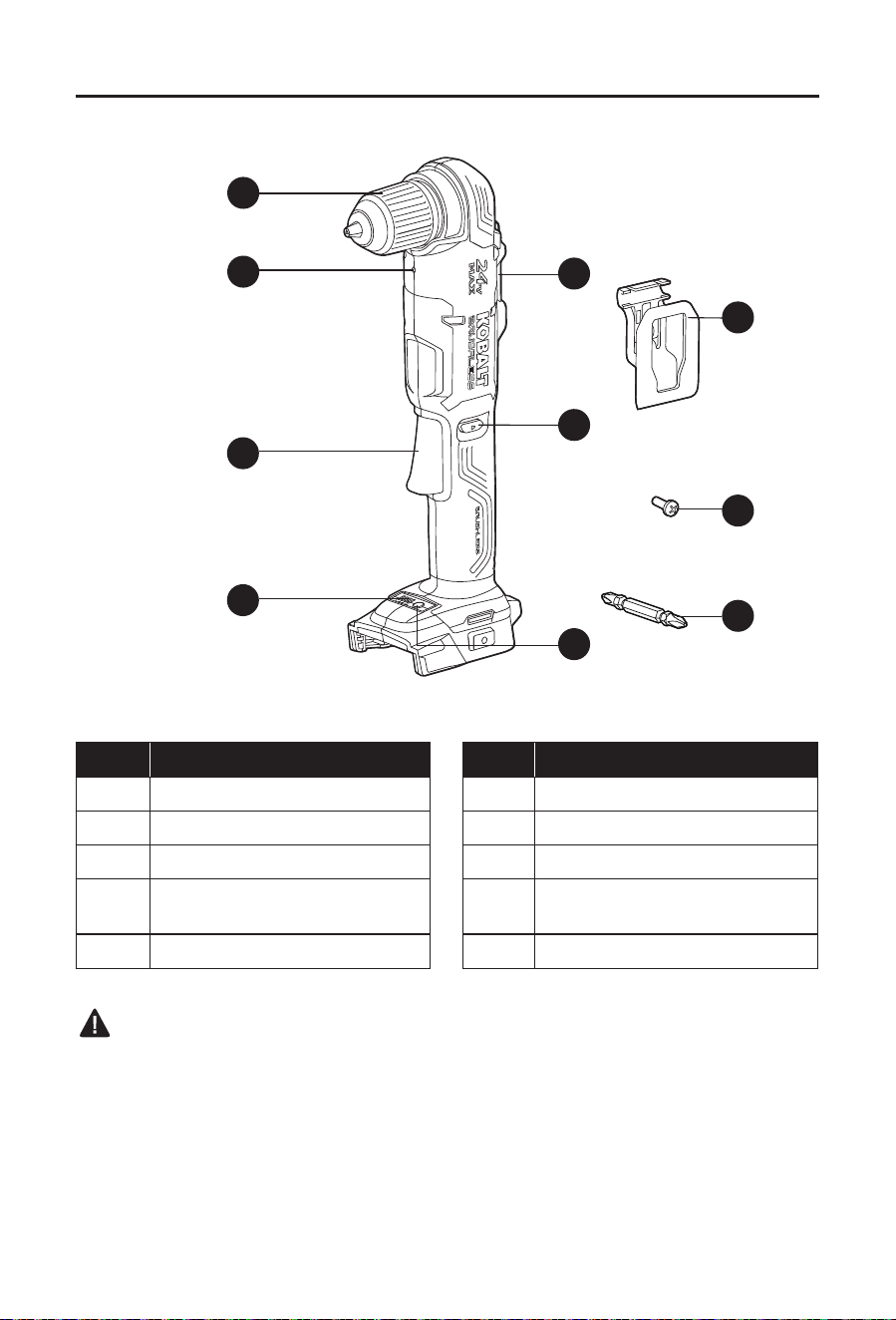
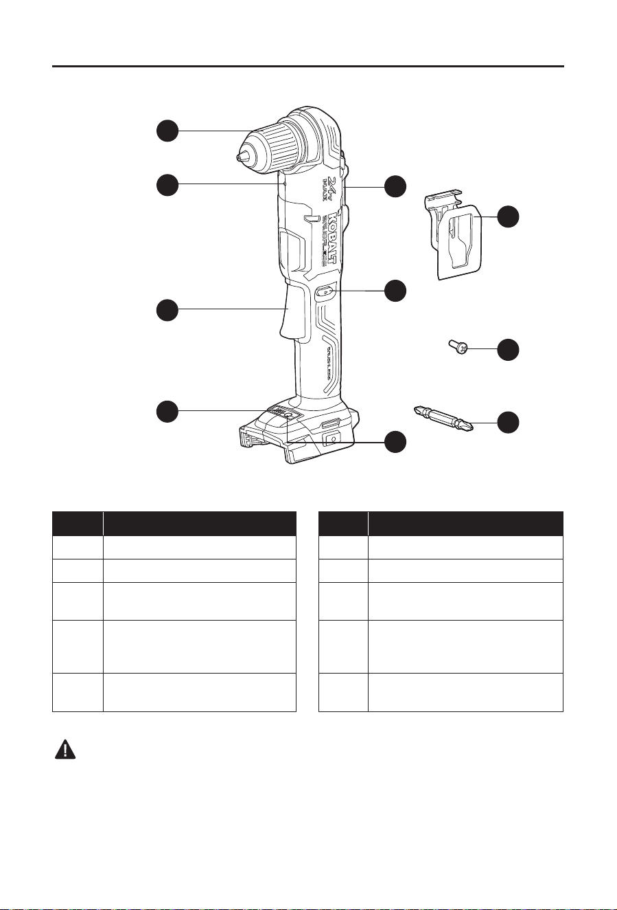
PACKAGE CONTENTS
G
B
A
F
E
J
I
C
D
H
PART DESCRIPTION PART DESCRIPTION
A Keyless chuck F Torque indicator
B Gear selector G Torque button
C LED worklight H Belt clip with bit holder
D
Direction-of-rotation selector
(forward/center-lock/reverse)
I Screw
E Variable-speed trigger switch J Double end bit
WARNING
• Remove the tool from the package and examine it carefully. Do not discard the carton or any
packaging material until all parts have been examined.
• If any part of the tool is missing or damaged, do not connect the battery to use the tool until
the part has been repaired or replaced. Failure to heed this warning could result in serious
injury.
4
SAFETY INFORMATION
Please read and understand this entire manual before attempting to assemble or operate
this product. If you have any questions regarding the product, please call customer service at
1-888-3KOBALT, 8 a.m. - 8 p.m., EST, Monday - Sunday.
WARNING
• The operation of any power tool can result in foreign objects being thrown into your eyes,
which can result in severe eye damage. Before beginning power-tool operation, always wear
safety goggles or safety glasses with side shields and a full-face shield, when needed. We
recommend using a wide vision safety mask over eyeglasses or standard safety glasses
with shields. Always use eye protection marked to comply with ANSI Z87.1.
• Some dust created by power sanding, sawing, grinding, drilling, and other construction
activities contains chemicals known to the state of California to cause cancer, birth defects,
or other reproductive harm. Some examples of these chemicals are:
– Lead from lead-based paints
– Crystalline silica from bricks, cement, and other masonry products
– Arsenic and chromium from chemically-treated lumber
• Your risk from these exposures varies, depending upon how often you do this type of work.
To reduce your exposure to these chemicals:
– Work in a well-ventilated area.
– Work with approved safety equipment, such as dust masks that are specially designed to
lter out microscopic particles.
– Avoid prolonged contact with dust from power sanding, sawing, grinding, drilling, and
other construction activities. Wear protective clothing and wash exposed areas with soap
and water. Allowing dust to get into your mouth or eyes or to lie on the skin may promote
absorption of harmful chemicals.
Know the Tool
To operate this tool, carefully read this manual and all labels afxed to the tool before using it.
Keep this manual available for future reference.
Important
This tool should be serviced only by a qualied service technician.
Read All Instructions Thoroughly
Some of the following symbols may be used on this tool. Please study them and their meaning.
Proper interpretation of these symbols will allow you to operate the tool better and more safely.
SYMBOL DEFINITION SYMBOL DEFINITION
V Volts n
0
No-load Speed
Direct Current /min Revolutions or Strokes per Minute
A danger, warning,
or caution. It means
‘Attention! Your safety
is involved.’
To reduce the risk of injury, user
must read instruction manual.

5
SAFETY INFORMATION
General Power Tool Safety Warnings
WARNING
• Read all safety warnings, instructions, illustrations and specications provided with
this power tool. Failure to follow all instructions listed below may result in electric shock,
re and/or serious injury.
Save all warnings and instructions for future reference
The term “power tool” in the warnings refers to your mains-operated (corded) power tool or
battery-operated (cordless) power tool.
Work Area Safety
• Keep work area clean and well lit. Cluttered or dark areas invite accidents.
• Do not operate power tools in explosive atmospheres, such as in the presence of
ammable liquids, gases or dust. Power tools create sparks, which may ignite the dust or
fumes.
• Keep children and bystanders away while operating a power tool. Distractions can
cause you to lose control.
Electrical Safety
• Power tool plugs must match the outlet. Never modify the plug in any way. Do not use
any adaptor plugs with earthed (grounded) power tools. Unmodied plugs and matching
outlets will reduce the risk of electric shock.
• Avoid body contact with earthed or grounded surfaces such as pipes, radiators,
ranges and refrigerators. There is an increased risk of electric shock if your body is
earthed or grounded.
• Do not expose power tools to rain or wet conditions. Water entering a power tool will
increase the risk of electric shock.
• Do not abuse the cord. Never use the cord for carrying, pulling or unplugging the
power tool. Keep cord away from heat, oil, sharp edges or moving parts. Damaged or
entangled cords increase the risk of electric shock.
• When operating a power tool outdoors, use an extension cord suitable for outdoor
use. Use of a cord suitable for outdoor use reduces the risk of electric shock.
• If operating a power tool in a damp location is unavoidable, use a residual current
device (RCD) protected supply. Use of an RCD reduces the risk of electric shock.
Personal Safety
• Stay alert, watch what you are doing and use common sense when operating a power
tool. Do not use a power tool while you are tired or under the inuence of drugs,
alcohol or medication. A moment of inattention while operating power tools may result in
serious personal injury.
• Use personal protective equipment. Always wear eye protection. Protective equipment
such as a dust mask, non-skid safety shoes, hard hat or hearing protection used for
appropriate conditions will reduce personal injuries
• Prevent unintentional starting. Ensure the switch is in the off-position before
connecting to power source and/or battery pack, picking up or carrying the tool.
Carrying power tools with your nger on the switch or energizing power tools that have the
switch on invites accidents.

6
SAFETY INFORMATION
• Remove any adjusting key or wrench before turning the power tool on. A wrench or a
key left attached to a rotating part of the power tool may result in personal injury.
• Do not overreach. Keep proper footing and balance at all times. This enables better
control of the power tool in unexpected situations.
• Dress properly. Do not wear loose clothing or jewelry. Keep your hair and clothing
away from moving parts. Loose clothes, jewelry or long hair can be caught in moving
parts.
• If devices are provided for the connection of dust extraction and collection facilities,
ensure that these are connected and properly used. Use of dust collection can reduce
dust-related hazards
• Do not let familiarity gained from frequent use of tools allow you to become
complacent and ignore tool safety principles. A careless action can cause severe injury
within a faction of a second.
Power tool use and care
• Do not force the power tool. Use the correct power tool for your application. The
correct power tool will do the job better and safer at the rate for which it was designed.
• Do not use the power tool if the switch does not turn it on and off. Any power tool that
cannot be controlled with the switch is dangerous and must be repaired.
• Disconnect the plug from the power source and/or remove the battery pack,
if detachable, from the power tool before making any adjustments, changing
accessories, or storing power tools. Such preventive safety measures reduce the risk of
starting the power tool accidentally.
• Store idle power tools out of the reach of children and do not allow persons
unfamiliar with the power tool or these instructions to operate the power tool. Power
tools are dangerous in the hands of untrained users.
• Maintain power tools and accessories. Check for misalignment or binding of moving
parts, breakage of parts and any other condition that may affect the power tool’s
operation. If damaged, have the power tool repaired before use. Many accidents are
caused by poorly maintained power tools.
• Keep cutting tools sharp and clean. Properly maintained cutting tools with sharp cutting
edges are less likely to bind and are easier to control.
• Use the power tool, accessories and tool bits etc. in accordance with these
instructions, taking into account the working conditions and the work to be
performed. Use of the power tool for operations different from those intended could result in
a hazardous situation.
• Keep handles and grasping surfaces dry, clean and free from oil and grease. Slippery
handles and grasping surfaces do not allow for safe handling and control of the tool in
unexpected situations.
Battery Tool Use and Care
• Recharge only with the charger specied by the manufacturer. A charger that is suitable
for one type of battery pack may create a risk of re when used with another battery pack.
• Use power tools only with specically designated battery packs. Use of any other
battery packs may create a risk of injury and re.
BATTERY PACK CHARGER
KB 124-03; KB 224-03; KB 424-03;
KB 524-03; KB 624-03; KXB 424-03
KRC 2445-03; KRC 2490-03;
KRC 2404-03

7
SAFETY INFORMATION
• When battery pack is not in use, keep it away from other metal objects, like paper
clips, coins, keys, nails, screws or other small metal objects, that can make a
connection from one terminal to another. Shorting the battery terminals together may
cause burns or a re.
• Under abusive conditions, liquid may be ejected from the battery; avoid contact. If
contact accidentally occurs, ush with water. If liquid contacts eyes, additionally seek
medical help. Liquid ejected from the battery may cause irritation or burns
• Do not use a battery pack or tool that is damaged or modied. Damaged or modied
batteries may exhibit unpredictable behavior resulting in re, explosion or risk of injury.
• Do not expose a battery pack or tool to re or excessive temperature. Exposure to re
or temperature above 130 °C may cause explosion.
• Follow all charging instructions and do not charge the battery pack or tool outside
the temperature range specied in the instructions. Charging improperly or at
temperatures outside the specied range may damage the battery and increase the risk of
re.
Service
• Have your power tool serviced by a qualied repair person using only identical
replacement parts. This will ensure that the safety of the power tool is maintained.
• Never service damaged battery packs. Service of battery packs should only be performed
by the manufacturer or authorized service providers.
Specic Safety Warnings for Wrench
• Use auxiliary handle(s), if supplied with the tool. Loss of control can cause personal
injury.
• Hold power tool by insulated gripping surfaces, when performing an operation where
the cutting accessory may contact hidden wiring. Cutting accessory contacting a “live”
wire may make exposed metal parts of the power tool “live” and could give the operator an
electric shock.
• Secure the workpiece. A workpiece clamped with clamping devices or in a vice is held
more secure than by hand.
• Always wait until the power tool has come to a complete stop before placing it down.
The tool insert can jam and lead to loss of control over the power tool.
PREPARATION
Know Your Right Angle Drill/Driver
This right angle drill/driver can be used for drilling and driving screws in all types of wood
products and metals. Before attempting to use the right angle drill/driver, familiarize yourself
with all of its operating features and safety requirements.
Helpful tool (not included): Phillips screwdriver.
WARNING
• Do not allow familiarity with the right angle drill/driver to cause carelessness. Remember
that one careless moment is enough to cause severe injury. Before attempting to use any
tool, be sure to become familiar with the operating features and safety instructions.
• Do not attempt to modify this tool or create accessories not recommended for use with this
tool. Any such alteration or modication is misuse and could result in a hazardous condition
leading to serious personal injury.
8
OPERATING INSTRUCTIONS
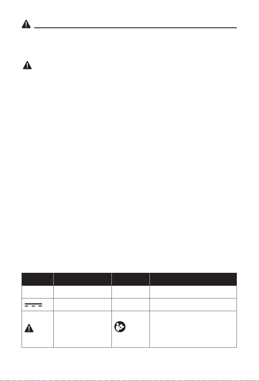
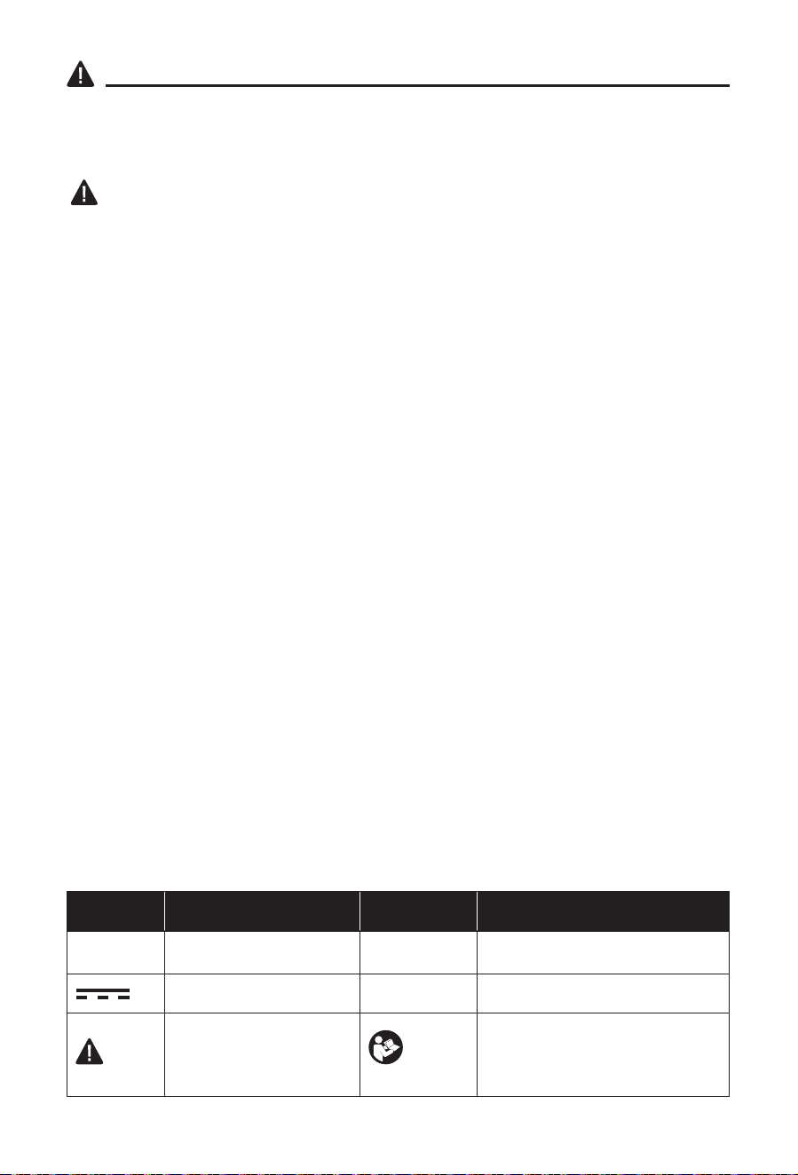
1. To Attach Battery Pack
a. Align the raised portion on the battery pack
with the grooves on the bottom of the tool,
then slide the battery pack onto the tool, as
shown.
b. Make sure that the battery-release buttons
on the battery pack snap into place and the
battery pack is secured to the tool before
beginning operation.
NOTICE: When placing the battery pack on the
tool, be sure that the raised rib on the battery pack
aligns with the groove on the tool and the latches
snap into place properly. Improper assembly of
the battery pack can cause damage to internal
components.
To Detach Battery Pack
a. Press the battery-release buttons to release the battery pack.
b. Pull backward on the battery pack to remove it from the tool.
WARNING
• Battery tools are always in operating condition. Therefore, always remove the battery pack
when the tool is not in use or when carrying the right angle drill/driver at your side.
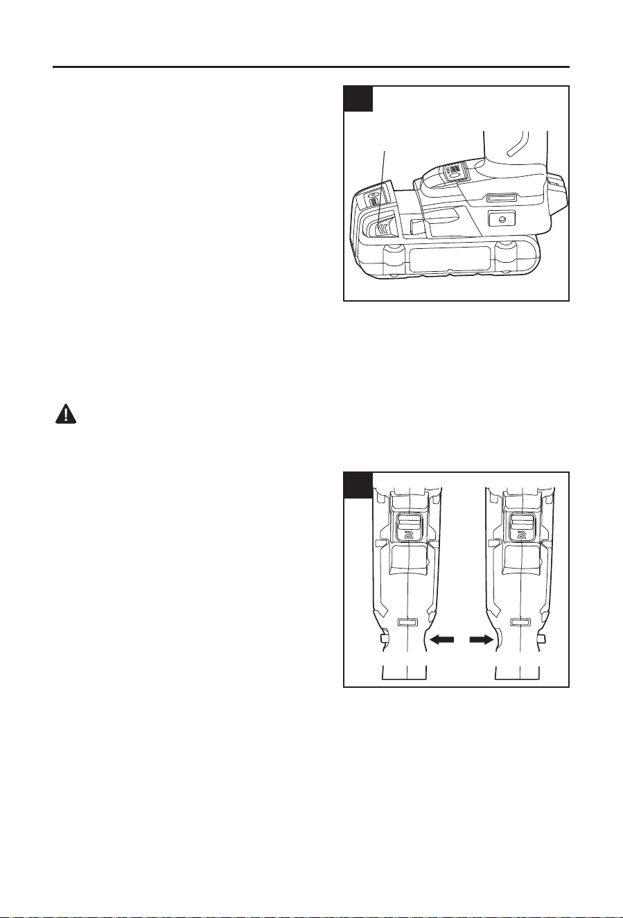
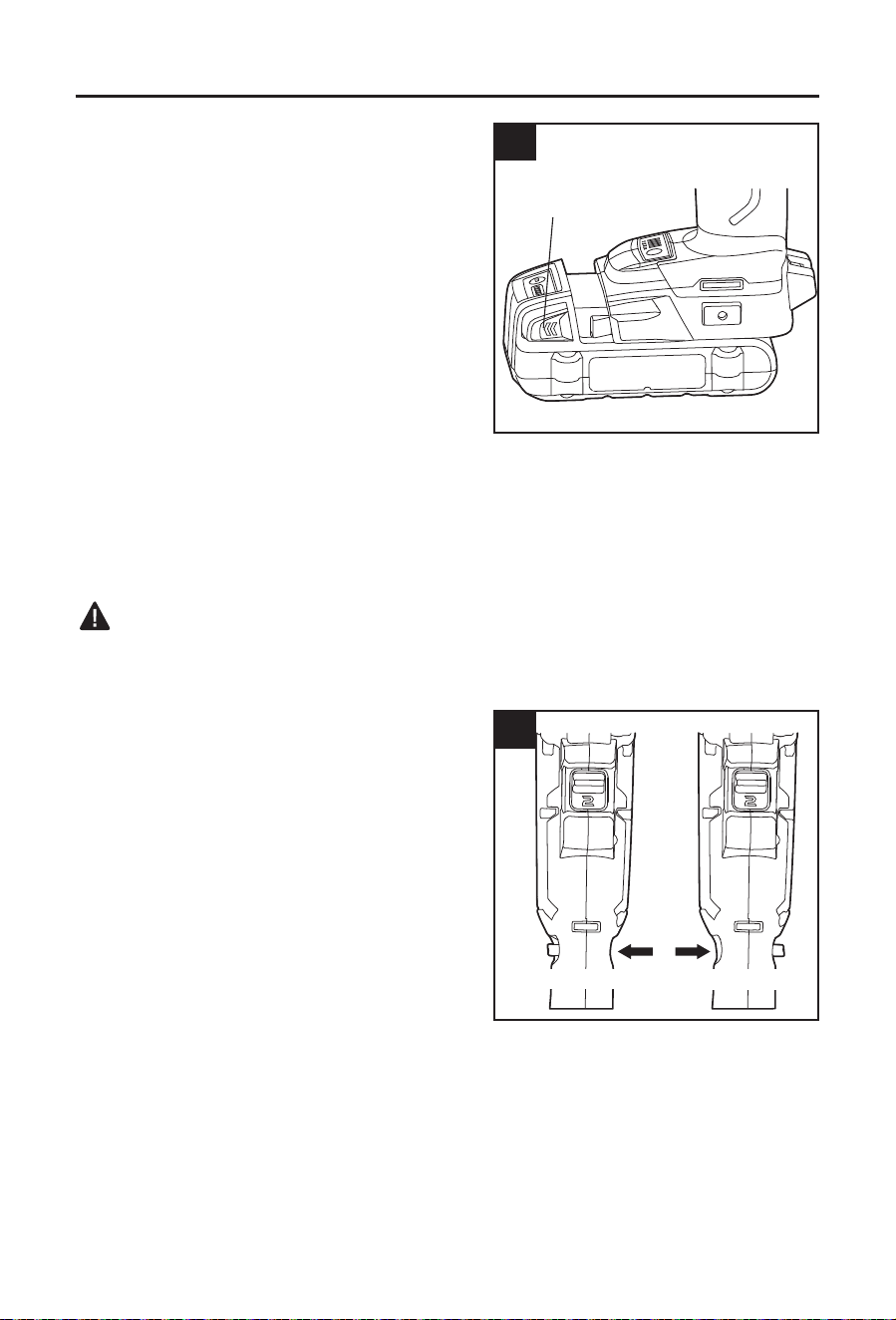
2. Direction-of-Rotation Selector
(Forward/Center-Lock/Reverse)
The direction of bit rotation is reversible and is
controlled by a selector (D) located near the
variable-speed trigger switch (E). With the right
angle drill/driver held in the normal operating
position, pointing away from you:
a. Position the direction-of-rotation selector (D) to
the left of the tool for forward rotation.
b. Position the direction-of-rotation selector to the
right of the tool for reverse rotation.
c. Setting the selector in the center-lock position
helps reduce the possibility of accidental
starting when the tool is not in use.
NOTICE: To prevent gear damage, always allow the right angle drill/driver to come to a
complete stop before changing the direction of rotation.
NOTICE: The right angle drill/driver will not run unless the direction-of-rotation selector is
engaged fully to the left or right.
1
Battery-release
button
2
Forward
Reverse
9
OPERATING INSTRUCTIONS
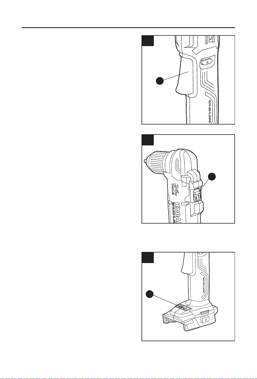
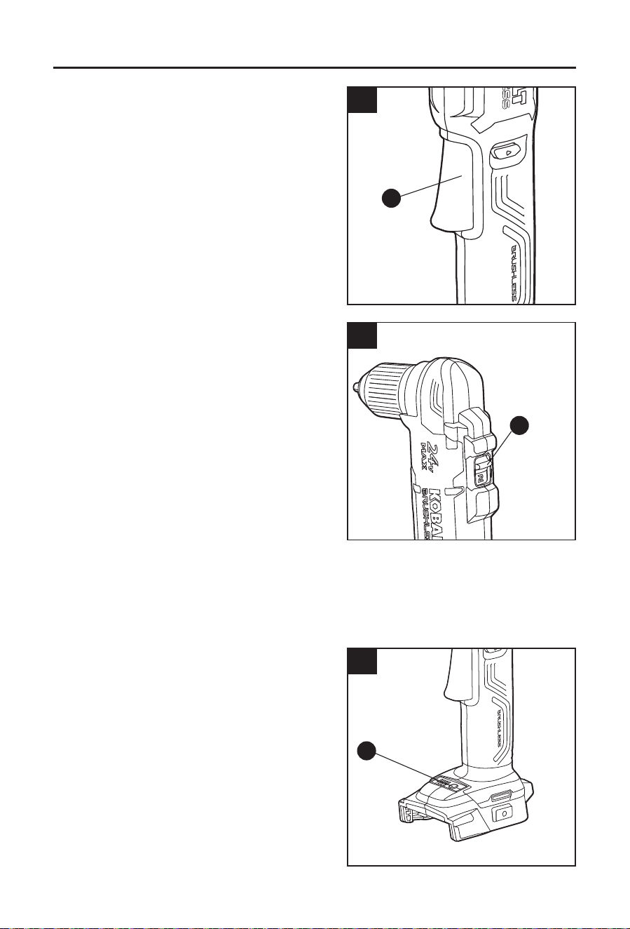
3. Variable-speed Trigger Switch
a. To turn the right angle drill/driver ON, depress
the variable-speed trigger switch (E).
b. To turn it OFF, release the variable-speed
trigger switch.
c. The variable-speed trigger switch delivers
higher speed with increased trigger pressure
and lower speed with decreased trigger
pressure.
4. Two-Speed Gear Box
The right angle drill/driver has a two-speed gear
box designed for drilling or driving at either of two
different variable-speed ranges. A gear selector (B)
is located on the top of the right angle drill/driver to
select either 1 (Low) or 2 (High) speed.
Setting 1 will deliver lower speeds and increased
power and torque. Use setting 1 for heavy-duty
work or for driving screws.
Setting 2 will deliver higher speeds and reduced
power and torque. Use setting 2 for drilling wood
and wood composites and for using abrasive and
polishing accessories.
NOTICE: Never change gears while the tool is running. Failure to obey this caution could
result in serious damage to the right angle drill/driver.
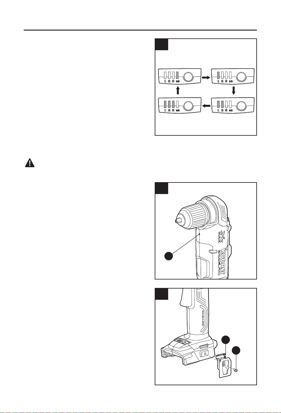
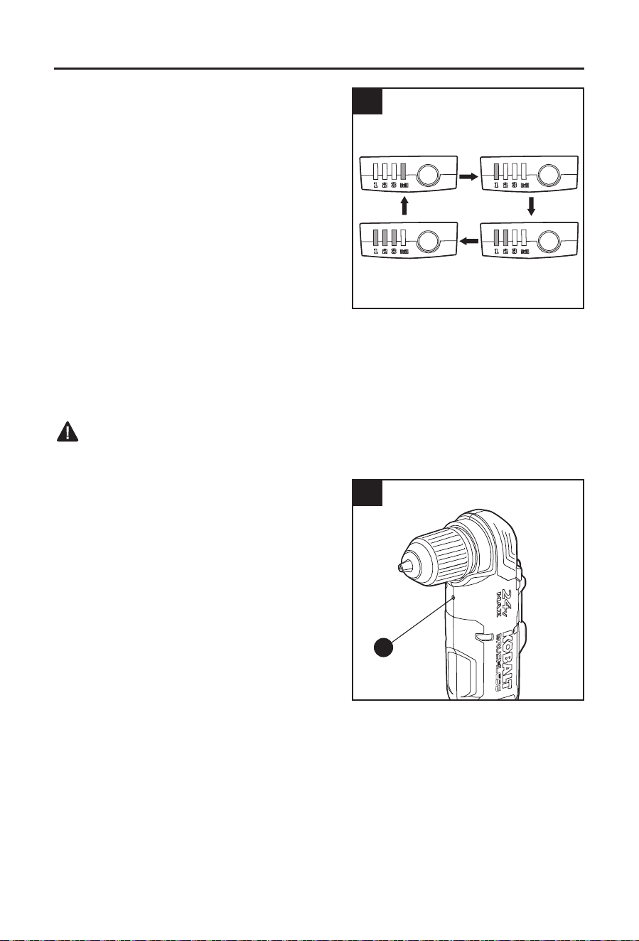
5. Adjustable Torque
The right angle drill/driver torque can be adjusted
among 3 driving settings and 1 drilling setting.
The tool defaults to the drill mode. When the
variable-speed trigger switch (E) is rst pressed, a
green light will shine in the torque indicator (F) to
indicate that the tool is in drill mode.
Press the torque button (G) one time to adjust the
tool to the drive setting.
1. The right angle drill provides lowest torque.
2. The right angle drill/driver provides medium
torque.
3. The right angle drill/driver provides maximum torque.
3
E
4
B
5a
G
10
OPERATING INSTRUCTIONS
The higher the torque setting, the more force the
right angle drill/driver produces to turn an object.
The proper setting depends on the job and the
type of bit, fastener, and material you will be
using. If the torque is too high, the screws may be
damaged or broken.
Select the drill mode for drilling and other heavy-duty
applications.
a. The torque indicator will blink to indicate that the
set torque is reached (only in 3-torques mode).
b. The LED indicator will turn off when the
direction-of-rotation selector is set to the
reverse direction, and will revert to the
previous setting when the selector is moved
back to the forward direction.
c. The LED indicator will turn off approximately 1 minute after the variable-speed trigger
switch is released.
WARNING
• Do not change the torque setting when the tool is operating.
6. LED Worklight
The LED worklight (C), located beneath the chuck,
will illuminate when the variable-speed trigger
switch (E) is depressed. This provides additional
light on the surface of the workpiece for operation
in lower-light conditions.
The LED worklight will turn off approximately 10
seconds after the variable-speed trigger switch is
released.
a. The LED worklight will blink rapidly if the
tool has stopped working in order to protect
internal circuits. Wait for the tool to cool down,
after which it can be started again.
b. The LED worklight will blink slowly to indicate
that the battery charge is very low.
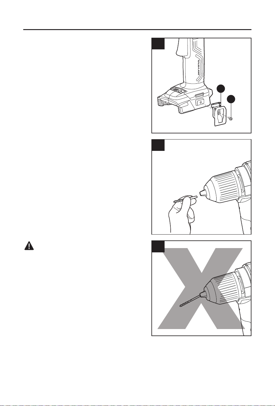
7. Installing and Removing the Belt Clip with
Bit Holder
a. Align the rib of the belt clip with Bit holder (H)
with the hole on the base of the right angle
drill/driver.
b. Tighten the screw (I) securely with a Phillips
screwdriver (not included).
c. To remove the belt clip with bit holder, use
a Phillips screwdriver to loosen the screw
holding the belt clip with bit holder to the right
angle drill/driver.
5b
6
C
7
H
I
11
OPERATING INSTRUCTIONS
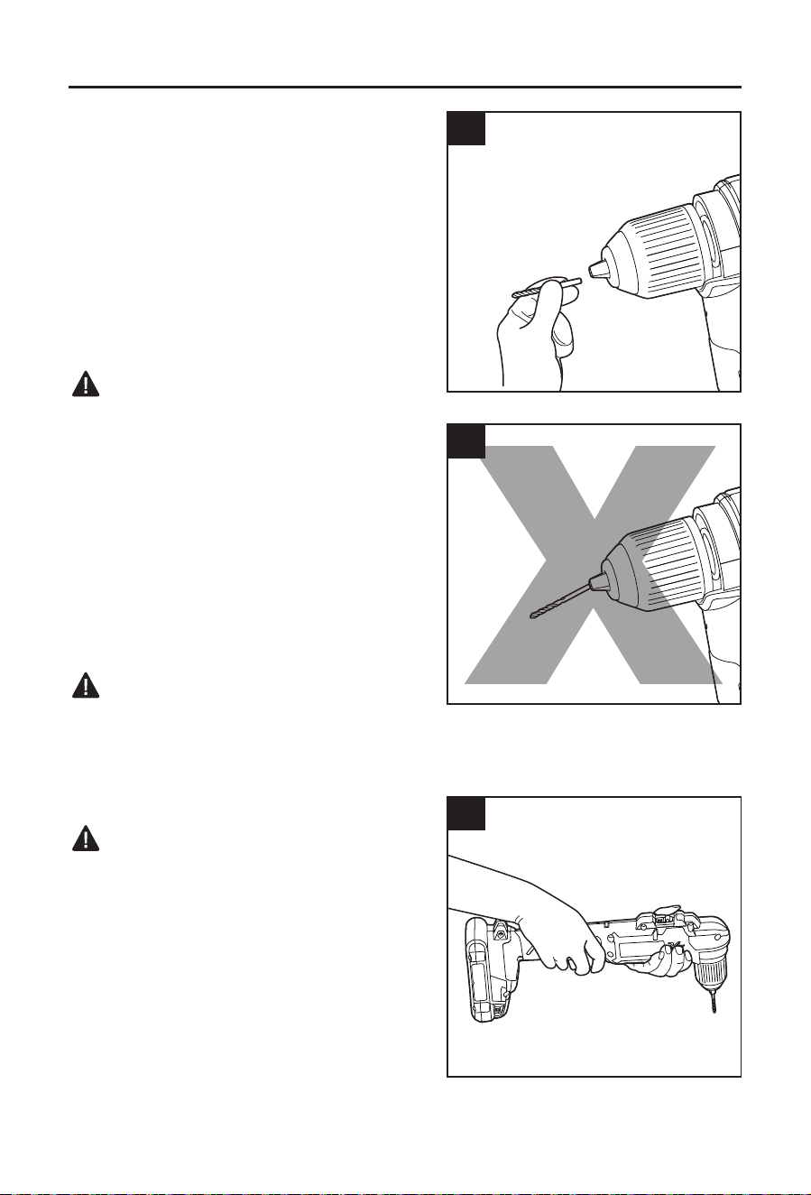
8. Installing Bits
a. Place the direction-of-rotation selector (D) in
the center-lock position.
b. Open or close the keyless chuck (A) to a point
where the opening is slightly larger than the
shank of the bit you intend to use.
c. Insert the double end bit.
d. Tighten the chuck jaws securely on the bit.
NOTICE: Rotate the keyless chuck in the direction of
the arrow marked GRIP to close the chuck jaws. Do
not use a wrench to tighten or loosen the chuck jaws.
WARNING
• Make sure to insert the drill bit straight into the
chuck jaws. Do not insert the drill bit into the
chuck jaws at a right angle and then tighten the
chuck, as shown in Fig. 8b. This could cause
the drill bit to be thrown from the right angle drill/
driver, resulting in possibly serious personal
injury or damage to the chuck.
Removing Bits
a. Place the direction-of-rotation selector (D) in
the center-lock position.
b. Open the chuck jaws with the keyless chuck (A).
c. Remove the drill bit.
WARNING
• Do not hold the chuck body with one hand and
use the power of the right angle drill/driver to tighten or loosen the chuck jaws on the drill bit.
The chuck body could slip in your hand, or your hand could slip and come in contact with the
rotating bit. This could cause an accident resulting in serious personal injury.
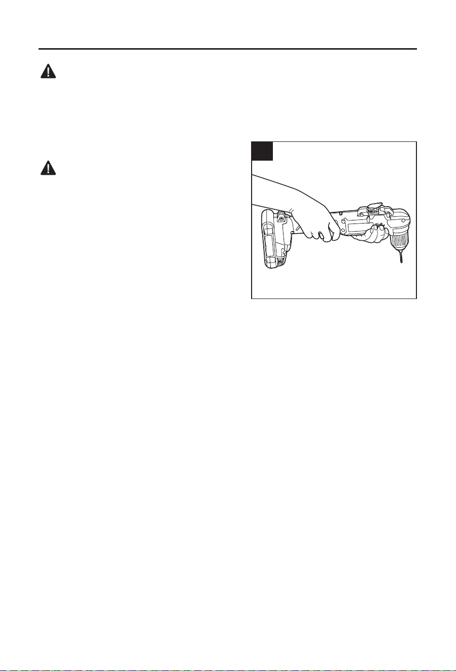
9. Drilling
WARNING
• Always wear safety goggles or safety glasses
with side shields during power-tool operation or
when blowing dust. If the operation is dusty, also
wear a dust mask.
a. Check the direction-of-rotation selector for the
correct setting (forward or reverse).
b. Secure the material to be drilled in a vise or
with clamps to keep it from turning as the drill
bit rotates.
c. Hold the right angle drill/driver rmly and place
the bit at the point to be drilled. Hold with two
hands, if needed.
8a
8b
9

12
OPERATING INSTRUCTIONS
d. Depress the variable-speed trigger switch (E) to start the right angle drill/driver.
e. Move the drill bit into the workpiece, applying only enough pressure to keep the bit drilling.
Do not force the right angle drill/driver or apply side pressure to elongate a hole. Let the
tool do the work.
f. When drilling hard, smooth surfaces, use a center punch (not included) to mark the desired
location of the hole. This will prevent the drill bit from slipping off-center as the hole is
started.
g. If the bit jams in the workpiece or if the right angle drill/driver stalls, stop the tool
immediately. Remove the bit from the workpiece and determine the reason for jamming.
h. To stop the right angle drill/driver, release the variable-speed trigger switch and allow the
tool to come to a complete stop.
Drilling in Wood
a. For maximum performance, use high-speed steel or brad-point bits for drilling wood.
b. Begin drilling at a very low speed to prevent the bit from slipping off the starting point.
c. Increase speed as the drill bit bites into the material.
d. When drilling “through” holes, place a block of wood behind the workpiece to prevent
ragged or splintered edges on the back side of the hole.
Drilling in Metal
a. For maximum performance, use high-speed steel bits for drilling metal or steel.
b. When drilling metals, use light oil on the drill bit to keep it from overheating. The oil will
prolong the life of the bit and increase the drilling action.
c. Begin drilling at a very low speed to prevent the bit from slipping off the starting point.
d. Maintain a speed and pressure which will allow cutting without overheating the bit.
Applying too much pressure will:
– Overheat the right angle drill/driver.
– Wear the bearings.
– Bend or burn bits.
– Produce off-center or irregular-shaped holes.
10. Screw Driving
a. Try to use modern screws for easy driving and improved grip.
b. It is advisable to drill a pilot hole rst. The pilot hole will act as a guide for the screw and
will also make tightening the screw less difcult.
c. Set the torque button (G) to the most suitable setting. If in doubt, start with a low setting,
then turn off the tool and increase the setting as needed.
NOTICE: Do not change the torque setting when the tool is running.
d. Keep sufcient pressure on the drill to prevent the bit from turning out of the screw head.
The screw head can easily become damaged, making it difcult to drive it home or
remove it.
13
CARE AND MAINTENANCE
All maintenance should only be carried out by a qualied service technician.
Cleaning
Before cleaning or performing any maintenance, remove the battery pack. For safe and proper
operation, always keep the tool and its ventilation slots clean.
Always use only a soft, dry cloth to clean your right angle drill/driver wrench; never use
detergent or alcohol.
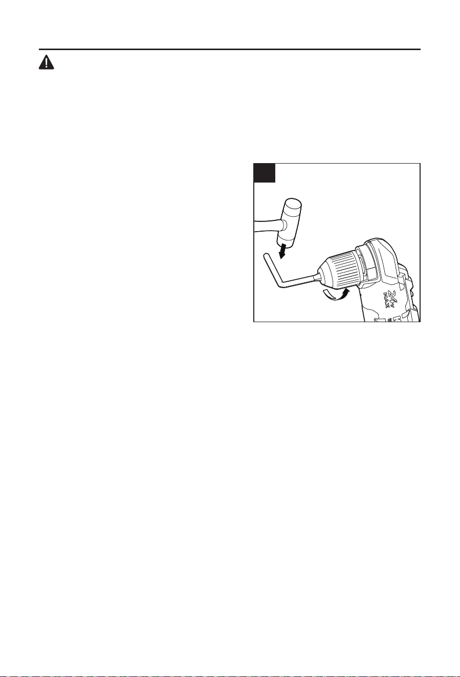
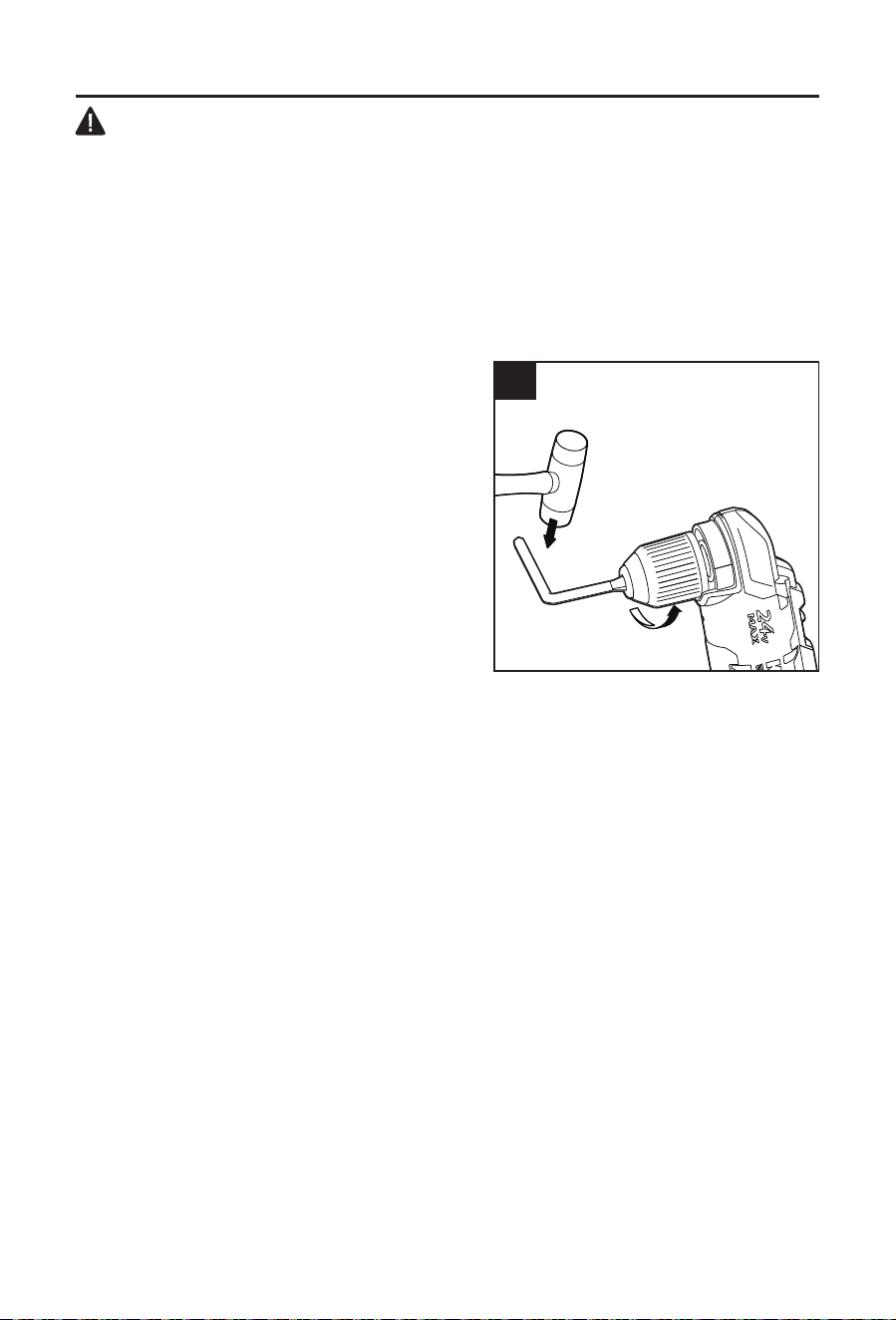
12. Chuck Removal
The chuck can be removed and replaced.
a. Lock the variable-speed trigger switch (E) by
placing the direction-of-rotation selector (D) in
the center-lock position.
b. Rotate the keyless chuck (A) to open the chuck
jaws.
c. Use a screwdriver to remove the chuck screw
by turning it in a clockwise direction.
d. Insert a 5/16-in. hex key (not included) into the
chuck of the right angle drill/driver and securely
tighten the chuck jaws around the hex key.
e. Tap the hex key sharply with a mallet in a
counterclockwise direction. This will loosen the
chuck for easy removal.
NOTICE: The chuck screw has left handed threads. Attach a new chuck to the spindle and
tighten the chuck screw.
12

14
TROUBLESHOOTING
WARNING
Turn the switch to the “OFF” position and remove the battery before performing troubleshooting
procedures.
PROBLEM POSSIBLE CAUSE CORRECTIVE ACTION
Tool does not work. Low battery capacity. Charge the battery pack.
Bit cannot be
installed.
Chuck is not released Release the chuck.
Bit does not t the
chuck.
Use an appropriate bit or use a suitable
adaptor.
Motor overheating Cooling vents are
obstructed
Clean and clear vents. Do not cover vents
with hand during operation
WARRANTY
For 5 years from the date of purchase, the tool is warranted for the original purchaser to be
free from defects in material and workmanship. This guarantee does not cover damage due
to abuse, normal wear, improper maintenance, neglect, unauthorized repair/alteration, or
expendable parts and accessories expected to become unusable after a reasonable period of
use. This warranty is limited to 90 days for commercial and rental use.
If you think your product meets the above guarantee criteria, please return it to the place of
purchase with valid proof of purchase and the defective product will be repaired or replaced at
no charge. This guarantee gives you specic legal rights, and you may also have other rights
that vary from state to state.
Printed in China
PH19519
¿Preguntas, problemas, piezas faltantes? Antes de volver a la tienda, llame a nuestro
Departamento de Servicio al Cliente al 1-888-3KOBALT (1-888-356-2258), de lunes a
viernes de 8 a.m. a 8 p.m., hora estándar del Este.
ADJUNTE SU RECIBO AQUÍ
Número de serie Fecha de compra
ARTÍCULO # 1439332
TALADRO/DESTORNILLADOR
EN ÁNGULO RECTO SIN
ESCOBILLAS
MODELO #KRAD 1224B-03

16
ÍNDICE
Especicaciones del producto ........................................................................16
Contenido del paquete ................................................................................... 17
Información de seguridad ...............................................................................18
Preparación ....................................................................................................22
Instrucciones de funcionamiento ....................................................................23
Cuidado y mantenimiento ..............................................................................29
Solución de problemas ...................................................................................30
Garantía .........................................................................................................30
ESPECIFICACIONES DEL PRODUCTO
COMPONENTE ESPECIFICACIONES
Rango de voltaje 24 V CC
Velocidad sin carga 0-600/0-2000 /min
Capacidad del mandril 3/8 pulg
Torsión máxima 250 pulg-lb
Temperatura de funcionamiento De -4 °F (-20 °C) a 113 °F (45 °C)
Temperatura de carga De 41 °F (5° C) a 104 °F (40 °C)
17
CONTENIDO DEL PAQUETE
G
B
A
F
E
J
I
C
D
H
PIEZA DESCRIPCIÓN PIEZA DESCRIPCIÓN
A Mandril sin llave F Indicador de torsión
B Selector de engranajes G Botón de torsión
C Luz de trabajo LED H
Presilla para cinturón con soporte
para brocas
D
Selector de dirección de rotación
(adelante, bloqueo central o
reversa)
I Tornillo
E
Interruptor tipo gatillo de
velocidad variable
J Broca doble
ADVERTENCIA
• Retire la herramienta del paquete y examínela cuidadosamente. No deseche la caja ni
ningún material de embalaje hasta después de examinar todas las piezas.
• Si alguna pieza está dañada o falta, no conecte la batería para usar la herramienta hasta
que se repare o reemplace la pieza. El incumplimiento de esta advertencia podría provocar
lesiones graves.
18
INFORMACIÓN DE SEGURIDAD
Lea y comprenda completamente este manual antes de intentar ensamblar u operar este
producto. Si tiene preguntas relacionadas con el producto, llame al Departamento de Servicio
al Cliente al 1-888-3KOBALT, de lunes a domingos de 8 a.m. a 8 p.m., hora estándar del Este.
ADVERTENCIA
• La operación de cualquier herramienta eléctrica puede provocar que objetos extraños
se arrojen a sus ojos y, de esta manera, se causen graves daños oculares. Use siempre
lentes o gafas de seguridad con protecciones laterales y, cuando sea necesario, una
mascarilla que cubra todo el rostro antes de comenzar a operar una herramienta eléctrica.
Recomendamos usar una máscara de seguridad de visión amplia sobre los lentes o gafas
de seguridad con protecciones estándar. Siempre use lentes de protección que cumplan
con la norma ANSI Z87.1.
• Parte del polvo producido por el lijado, el serruchado, la trituración y el taladrado eléctrico y
otras actividades de construcción contiene sustancias químicas reconocidas por el estado
de California como causantes de cáncer, defectos congénitos u otros daños en el aparato
reproductivo. Algunos ejemplos de estos productos químicos son los siguientes:
– Plomo de pinturas a base de plomo
– Sílice cristalina de ladrillos, cemento y otros productos de mampostería
– Arsénico y cromo de madera tratada con químicos
• El riesgo que corre debido a la exposición a estos productos químicos varía según la
frecuencia con la que realiza este tipo de trabajo. Para reducir la exposición a estos
productos químicos:
– Trabaje en un área bien ventilada.
– Trabaje con equipo de seguridad aprobado, como las mascarillas antipolvo
especialmente diseñadas para ltrar partículas microscópicas.
– Evite estar en contacto prolongado con el polvo provocado por el lijado, el aserrado, la
trituración y el taladrado y otras actividades de construcción. Use ropa protectora y lave
todas las áreas expuestas del cuerpo con agua y jabón. Si el polvo ingresa a la boca o a
los ojos o cae sobre la piel, podría provocar la absorción de productos químicos dañinos.
Conozca la herramienta
Para operar esta herramienta, lea cuidadosamente este manual y las etiquetas jadas a la
herramienta antes de usarla. Guarde este manual para referencia futura.
Importante
Solo un técnico calicado puede reparar esta herramienta.
Lea por completo todas las instrucciones
Algunos de los siguientes símbolos pueden aplicarse al uso de esta herramienta. Obsérvelos
y aprenda su signicado. La interpretación correcta de estos símbolos le permitirá utilizar la
herramienta de manera más ecaz y segura.
SÍMBOLO DEFINICIÓN SÍMBOLO DEFINICIÓN
V Voltios n
0
Velocidad sin carga
Corriente continua /min Revoluciones o carreras por minuto
Peligro, advertencia o
precaución. Signica
"¡Atención! Su seguridad
está comprometida".
Para reducir el riesgo de
lesiones, el usuario debe leer el
manual de instrucciones.

19
INFORMACIÓN DE SEGURIDAD
Advertencias generales de seguridad en el manejo de herramientas eléctricas
ADVERTENCIA
• Lea todas las advertencias de seguridad, las instrucciones, las ilustraciones y las
especicaciones que se incluyen para esta herramienta eléctrica. No cumplir con todas
las instrucciones que se detallan a continuación podría provocar descargas eléctricas,
incendios o lesiones graves.
Guarde todas las advertencias e instrucciones para referencia futura
El término “herramienta eléctrica” que aparece en las advertencias hace referencia a la
herramienta eléctrica que se conecta a la línea principal (con cable) o a la herramienta
eléctrica que funciona a batería (inalámbrica).
Seguridad en el área de trabajo
• Mantenga el área de trabajo limpia y bien iluminada. Las áreas desordenadas u
oscuras aumentan las posibilidades de accidentes.
• No utilice herramientas eléctricas en atmósferas en las que exista riesgo de
explosión, como por ejemplo en presencia de líquidos inamables, gases o polvo.
Las herramientas eléctricas producen chispas que podrían encender el polvo o humo.
• Mantenga a los niños y a otras personas alejados mientras utiliza una herramienta
eléctrica. Las distracciones pueden hacerle perder el control.
Seguridad eléctrica
• Los enchufes de las herramientas eléctricas deben encajar en el tomacorriente.
No modique el enchufe de ninguna manera. No utilice ningún enchufe adaptador con
herramientas eléctricas con puesta a tierra. Los enchufes sin modicaciones y que encajan
en los tomacorrientes reducen el riesgo de descarga eléctrica.
• Evite el contacto del cuerpo con supercies conectadas a tierra, como tuberías,
radiadores, extractores o refrigeradores. También puede sufrir una descarga eléctrica si
su cuerpo tiene conexión a tierra.
• No exponga las herramientas eléctricas a la lluvia ni a condiciones de humedad. Si
ingresa agua en una herramienta eléctrica, el riesgo de descarga eléctrica aumentará.
• No maltrate el cable. Nunca use el cable para transportar, jalar ni desenchufar la
herramienta eléctrica. Mantenga el cable alejado del calor, el aceite, los bordes losos
o las piezas en movimiento. Los cables dañados o enredados aumentan el riesgo de
descarga eléctrica.
• Si utiliza una herramienta eléctrica en exteriores, use un cable de extensión para uso
en exteriores. Usar un cable apto para exteriores reduce el riesgo de sufrir una descarga
eléctrica.
• Si es inevitable utilizar una herramienta eléctrica en un lugar húmedo, use un
suministro protegido con un interruptor diferencial residual (RCD, por sus siglas en
inglés). El uso de un RCD disminuye el riesgo de descargas eléctricas.
Seguridad personal
• Manténgase alerta, preste atención a lo que hace y utilice el sentido común cuando
utilice una herramienta eléctrica. No utilice una herramienta eléctrica si está cansado
o bajo los efectos de drogas, alcohol o medicamentos. Un momento de desatención
mientras opera herramientas eléctricas puede provocar lesiones personales graves.

20
INFORMACIÓN DE SEGURIDAD
• Use equipo de protección personal. Use siempre lentes de protección. Los equipos
de protección, como mascarillas antipolvo, zapatos de seguridad antideslizantes, cascos
protectores o protección auditiva, utilizados para las condiciones adecuadas, disminuyen el
riesgo de lesiones personales.
• Evite un arranque accidental. Asegúrese de que el interruptor esté en la posición de
apagado antes de conectar la herramienta a la fuente de alimentación o al paquete de
baterías, o antes de levantarla o transportarla. Transportar herramientas eléctricas con el
dedo en el interruptor o enchufar herramientas eléctricas que tienen el interruptor encendido
aumenta las posibilidades de accidentes.
• Retire todas las llaves de ajuste o llaves inglesas antes de encender la herramienta
eléctrica. Si se deja una llave inglesa o una llave conectada a una pieza giratoria de la
herramienta eléctrica, se podrían producir lesiones personales.
• No se extienda demasiado. Mantenga una postura y un equilibrio adecuados en
todo momento. Esto permite un mejor control de la herramienta eléctrica en situaciones
inesperadas.
• Use ropa adecuada. No use ropa holgada ni joyas. Mantenga el cabello y la ropa
alejados de las piezas en movimiento. La ropa holgada, las joyas o el cabello largo
pueden quedar atrapados en las piezas en movimiento.
• Si se proporcionan dispositivos para la conexión de equipos de extracción y
recolección de polvo, asegúrese de que se conecten y se usen debidamente. La
recolección de polvo puede disminuir los peligros relacionados con el polvo
• No permita que la familiaridad obtenida por el uso frecuente de las herramientas
ocasione el olvido de los principios de seguridad en el manejo de herramientas. Un
descuido puede ocasionar una lesión grave en cuestión de segundos.
Uso y cuidado de las herramientas eléctricas
• No fuerce la herramienta eléctrica. Use la herramienta eléctrica adecuada para la
tarea. La herramienta eléctrica adecuada realizará un trabajo más seguro y de mejor
calidad al ritmo para el que se diseñó.
• No utilice la herramienta eléctrica si no la puede encender o apagar con el interruptor.
Cualquier herramienta eléctrica que no pueda controlarse con el interruptor es peligrosa y
debe repararse.
• Desconecte el enchufe de la fuente de alimentación o retire el paquete de baterías
de la herramienta eléctrica (si es posible) antes de realizar cualquier ajuste, cambiar
accesorios o almacenar herramientas eléctricas. Este tipo de medidas de seguridad
preventivas reduce el riesgo de arranques accidentales de la herramienta eléctrica.
• Almacene las herramientas eléctricas que no estén en uso fuera del alcance de los
niños y no permita que las personas que no conozcan cómo usar la herramienta o
estas instrucciones la utilicen. Las herramientas eléctricas son peligrosas en manos de
usuarios sin capacitación.
• Realice mantenimiento a las herramientas eléctricas y a los accesorios. Revise si
hay piezas móviles desalineadas o trabadas, si hay piezas rotas y cualquier otra
condición que pueda afectar el funcionamiento de la herramienta eléctrica. Si se daña
la herramienta eléctrica, hágala reparar antes de usarla. Muchos accidentes son producto
del mantenimiento incorrecto de las herramientas eléctricas.
• Mantenga las herramientas de corte aladas y limpias. Las herramientas de corte que
se mantienen adecuadamente, con sus bordes de corte alados, son menos propensas a
trabarse y son más fáciles de controlar.
• Use la herramienta eléctrica, los accesorios, las brocas, etc. de acuerdo con estas
instrucciones y considerando las condiciones de trabajo y la tarea que desea realizar.
Si la herramienta eléctrica se utiliza en operaciones para las que no se diseñó, se podrían
ocasionar situaciones de peligro.

21
INFORMACIÓN DE SEGURIDAD
• Mantenga los mangos y las supercies de agarre secos, limpios y sin aceite ni grasa.
Los mangos y las supercies de agarre resbaladizos no permiten manipular ni controlar la
herramienta de forma segura en situaciones inesperadas.
Uso y cuidado de herramientas a batería
• Recargue solo con el cargador especicado por el fabricante. Un cargador adecuado
para un tipo de paquete de baterías puede causar un riesgo de incendio si se usa con otro
paquete de baterías.
• Use las herramientas eléctricas solo con los paquetes de baterías especícamente
designados para estas. El uso de cualquier otro paquete de baterías puede crear un
riesgo de lesión e incendio.
PAQUETE DE BATERÍAS CARGADOR
KB 124-03; KB 224-03; KB 424-03;
KB 524-03; KB 624-03; KXB 424-03
KRC 2445-03; KRC 2490-03;
KRC 2404-03
• Cuando el paquete de baterías no está en uso, aléjelo de objetos metálicos, tales
como sujetapapeles, monedas, llaves, clavos, tornillos u otros objetos metálicos
pequeños que pudieran crear una conexión entre los terminales. Si se conectan los
terminales de la batería entre sí, puede que se produzcan quemaduras o un incendio.
• En condiciones de maltrato, es posible que salga líquido de la batería. Evite el
contacto. Si se produce un contacto accidental, enjuague con agua. Si el líquido
entra en contacto con los ojos, solicite atención médica. El líquido que sale de la
batería puede provocar irritación o quemaduras.
• No utilice un paquete de baterías ni una herramienta si están dañados o modicados.
Las baterías dañadas o modicadas pueden mostrar una conducta impredecible que podría
provocar incendios, explosiones o riesgo de lesiones.
• No exponga el paquete de baterías ni la herramienta al fuego ni a una temperatura
excesiva. La exposición al fuego o a las temperaturas por encima de los 130 °C puede
causar explosión.
• Siga todas las instrucciones de carga y no cargue el paquete de baterías ni las
herramientas fuera del rango de temperatura especicado en las instrucciones.
Realizar una carga inadecuada o a temperaturas fuera del rango especicado podría dañar
la batería y aumentar el riesgo de incendio.
Reparación
• Permita que solo una persona capacitada repare la herramienta eléctrica y que utilice
únicamente piezas de repuesto idénticas a las de fábrica. De esta forma, se asegurará
de mantener la seguridad de la herramienta eléctrica.
• Nunca realice mantenimiento a los paquetes de baterías. Solo el fabricante o los
proveedores de servicio autorizados pueden realizar este tipo de mantenimiento.
Advertencias de seguridad especícas para la llave
• Use los mangos auxiliares, si se suministran con la herramienta. La pérdida de control
puede causar lesiones personales graves.
• Sostenga la herramienta eléctrica por las supercies de agarre aisladas al realizar
una operación en la que el accesorio de corte pueda entrar en contacto con
cableado oculto. Es posible que un accesorio de corte que entre en contacto con un cable
“energizado” también “energice” las piezas de metal expuestas de la herramienta eléctrica y
provoque una descarga eléctrica al operador.

22
INFORMACIÓN DE SEGURIDAD
• Asegure la pieza de trabajo. Las piezas de trabajo pueden sostenerse de forma más
segura con dispositivos de sujeción que con las manos.
• Siempre espere hasta que la herramienta eléctrica se detenga completamente antes
de colocarla hacia abajo. El accesorio de la herramienta se puede atascar y provocar la
pérdida de control sobre la herramienta eléctrica.
PREPARACIÓN
Conozca el taladro/destornillador en ángulo recto
Este taladro/destornillador en ángulo recto se puede utilizar para perforar y apretar tornillos en
productos de todo tipo de madera y metales. Antes de intentar usar el taladro/destornillador
en ángulo recto, familiarícese con todas sus características de operación y requisitos de
seguridad.
Herramienta útil (no se incluye): Destornillador Phillips.
ADVERTENCIA
• Sea cuidadoso, incluso si está familiarizado con el taladro/destornillador en ángulo recto.
Recuerde que un momento de descuido es suciente para causar lesiones graves. Antes
de intentar utilizar cualquier herramienta, asegúrese de familiarizarse con las funciones de
operación y las instrucciones de seguridad.
• No intente modicar esta herramienta ni crear accesorios que no sean los recomendados
para esta. Se considera que cualquier alteración o modicación es un mal uso, el cual
podría causar una condición peligrosa y ocasionar lesiones personales graves.
23
INSTRUCCIONES DE FUNCIONAMIENTO
1. Para jar el paquete de baterías
a. Alinee la parte elevada del paquete de
baterías con las ranuras de la parte inferior de
la herramienta y luego deslice el paquete de
baterías en la herramienta, como se muestra.
b. Asegúrese de que los botones de liberación
de la batería del paquete de baterías encajen
en su lugar y que el paquete de baterías
quede jo a la herramienta antes de comenzar
la operación.
AVISO: al colocar el paquete de baterías en la
herramienta, asegúrese de que la varilla elevada
del paquete de baterías se alinee con la ranura
de la herramienta y que los pestillos encajen en
su lugar adecuadamente. El ensamblaje inadecuado del paquete de baterías puede provocar
daños a los componentes internos.
Para retirar el paquete de baterías
a. Presione los botones de liberación de la batería para liberar el paquete de baterías.
b. Jale el paquete de baterías hacia atrás para retirarlo de la herramienta.
ADVERTENCIA
• Las herramientas que funcionan a batería siempre están en condiciones de funcionamiento.
Por lo tanto, siempre retire el paquete de baterías cuando no use el taladro/destornillador
en ángulo recto o cuando lo transporte junto a usted.
2. Selector de dirección de rotación
(adelante, bloqueo central o reversa)
La dirección de rotación de la broca es reversible y
se controla mediante el selector (D) ubicado cerca
del interruptor tipo gatillo de velocidad variable
(E). Con el taladro/destornillador en ángulo recto
sostenido en la posición de operación normal,
apuntando en dirección opuesta a usted:
a. Coloque el selector de dirección de rotación
(D) a la izquierda de la herramienta para que
gire hacia delante.
b. Coloque el selector de dirección de rotación a
la derecha de la herramienta para que gire en
reversa.
c. Fijar el selector en la posición de bloqueo central ayuda a reducir la posibilidad de
arranque accidental cuando no se está utilizando la herramienta.
AVISO: para evitar que los engranajes se dañen, siempre deje que el taladro/destornillador en
ángulo recto se detenga por completo antes de cambiar la dirección de la rotación.
AVISO: el taladro/destornillador en ángulo recto no funcionará a menos que el selector de
dirección de rotación esté completamente posicionado a la izquierda o a la derecha.
1
Botón de liberación
de la batería
2
Adelante
Reversa
24
INSTRUCCIONES DE FUNCIONAMIENTO
3. Interruptor tipo gatillo de velocidad variable
a. Para encender el taladro/destornillador en
ángulo recto, presione el interruptor tipo gatillo
de velocidad variable (E).
b. Para apagarlo, suelte el interruptor tipo gatillo
de velocidad variable.
c. El interruptor tipo gatillo de velocidad variable
proporciona mayor velocidad con mayor
presión en el gatillo y menor velocidad con
menor presión en el gatillo.
4. Caja de dos velocidades
El taladro/destornillador en ángulo recto cuenta
con una caja de engranaje de dos velocidades
diseñada para taladrar o atornillar a dos rangos
de velocidad variable diferentes. En la parte
superior del taladro/destornillador en ángulo recto,
se encuentra un selector de engranaje (B) para
seleccionar velocidad 1 (baja) o 2 (alta).
La conguración 1 ofrece velocidades más bajas
y mayor potencia y torsión. Use la conguración 1
para trabajo pesado o para apretar tornillos.
La conguración 2 tiene velocidades más
altas y potencia y torsión reducidos. Use
la conguración 2 para taladrar madera y
compuestos de madera, y para accesorios
abrasivos y de pulido.
AVISO: nunca cambie los engranajes mientras la herramienta esté en funcionamiento. No
obedecer esta medida de precaución podría causar daños graves en el taladro/destornillador
en ángulo recto.
5. Torsión ajustable
La torsión del taladro/destornillador en ángulo
recto puede ajustarse en 3 conguraciones para
atornillar y en 1 conguración para taladrar.
La herramienta está congurada de forma
predeterminada en el modo de taladro. Cuando
se presione el interruptor tipo gatillo de velocidad
variable (E) por primera vez, se encenderá una luz
verde en el indicador de torsión (F) para indicar
que la herramienta está en modo de taladro.
Presione el botón de torsión (G) una vez para
ajustar la herramienta a la conguración del
destornillador.
3
E
4
B
5a
G
25
INSTRUCCIONES DE FUNCIONAMIENTO
1. El taladro en ángulo recto proporciona fuerza
de torsión mínima.
2. El taladro/destornillador en ángulo recto
proporciona fuerza de torsión media.
3. El taladro/destornillador en ángulo recto
proporciona fuerza de torsión máxima.
A mayor conguración de torsión, mayor fuerza
produce el taladro/destornillador en ángulo recto
para girar un objeto. La conguración correcta
depende del trabajo y del tipo de broca, sujetador
y material que utilice. Si la torsión es demasiado
elevada, los tornillos podrían dañarse o quebrarse.
Seleccione el modo de taladrado para taladrar y
para otras aplicaciones para trabajo pesado.
a. El indicador de torsión titilará para indicar que
se alcanzó la torsión de ajuste (solo en modo de tres torsiones).
b. El indicador LED se apagará cuando el selector de dirección de rotación se ajuste en
reversa y volverá a la conguración previa cuando el selector se regrese a la dirección
hacia delante.
c. El indicador LED se apagará aproximadamente 1 minuto después de que suelte el
interruptor tipo gatillo de velocidad variable.
ADVERTENCIA
• No cambie la conguración de torsión mientras la herramienta está en funcionamiento.
6. Luz de trabajo LED
La luz de trabajo LED (C), ubicada debajo del
mandril, se encenderá cuando presione el
interruptor tipo gatillo de velocidad variable (E).
Esto brinda más iluminación en la supercie de
la pieza de trabajo para usar la herramienta en
condiciones de poca iluminación.
La luz de trabajo LED se apagará
aproximadamente 10 segundos después de
que suelte el interruptor tipo gatillo de velocidad
variable.
a. La luz de trabajo LED titilará rápidamente si la
herramienta deja de funcionar para proteger
los circuitos internos. Espere hasta que la
herramienta se enfríe para volver a hacerla funcionar.
b. La luz de trabajo LED titilará de forma pausada para indicar que la carga de la batería se
encuentra demasiado baja.
5b
6
C
26
INSTRUCCIONES DE FUNCIONAMIENTO
7. Instalación y retiro de la presilla para
cinturón con soporte para brocas
a. Alinee la pestaña de la presilla para cinturón
con soporte para brocas (H) con el oricio en
la base del taladro/destornillador en ángulo
recto.
b. Apriete el tornillo (I) con rmeza con un
destornillador Phillips (no se incluye).
c. Para retirar la presilla para cinturón con
soporte para brocas, utilice un destornillador
Phillips para aojar el tornillo que ja la
presilla para cinturón con soporte para brocas
al taladro/destornillador en ángulo recto.
8. Instalación de las brocas
a. Coloque el selector de dirección de rotación (D)
en la posición de bloqueo central.
b. Abra o cierre el mandril sin llave (A) hasta que
la abertura sea un poco más grande que el
vástago de la broca que va a usar.
c. Inserte la broca doble.
d. Apriete bien las mordazas del mandril en la
broca.
AVISO: gire el mandril sin llave en la dirección de la
echa GRIP (agarre) para cerrar las mordazas del
mandril. No utilice una llave inglesa para apretar o
aojar las mordazas del mandril.
ADVERTENCIA
• Asegúrese de colocar la broca para taladro
de forma derecha dentro de las mordazas
del mandril. No coloque la broca para taladro
dentro de las mordazas del mandril en ángulo
recto para luego apretar el mandril, como se
muestra en la Fig. 8b. Esto puede hacer que la
broca para taladro salga disparada del taladro/
destornillador en ángulo recto, lo que puede
producir lesiones serias o daños al mandril.
Retiro de las brocas
a. Coloque el selector de dirección de rotación (D)
en la posición de bloqueo central.
b. Abra las mordazas del mandril con el mandril sin llave (A).
c. Retire la broca para taladro.
7
H
I
8a
8b
27
INSTRUCCIONES DE FUNCIONAMIENTO
ADVERTENCIA
• No sostenga el cuerpo del mandril con una sola mano y use la potencia del taladro/
destornillador en ángulo recto para apretar o desajustar las mordazas del mandril en la
broca para taladro. El cuerpo del mandril se puede resbalar en la mano, o la mano puede
resbalarse y entrar en contacto con la pieza giratoria. Esto puede provocar un accidente
que resulte en lesiones personales graves.
9. Para perforar
ADVERTENCIA
• Use siempre gafas o anteojos de seguridad con
protectores laterales durante la operación de
la herramienta eléctrica o al soplar el polvo. Si
hay demasiado polvo durante la operación, use
también una mascarilla antipolvo.
a. Verique que el selector de dirección de
rotación esté en la conguración correcta
(hacia delante o en reversa).
b. Asegure el material que va a perforar en un
tornillo de banco o con abrazaderas para evitar
que gire cuando la broca para taladro esté
girando.
c. Sostenga el taladro/destornillador en ángulo recto con rmeza y coloque la broca en el
punto que va a perforar. Sostenga la herramienta con las dos manos si es necesario.
d. Presione el interruptor tipo gatillo de velocidad variable (E) para arrancar el taladro/
destornillador en ángulo recto.
e. Mueva la broca para taladro en la pieza de trabajo, aplicando la presión suciente para
mantener la broca taladrando. No fuerce el taladro/destornillador en ángulo recto ni
aplique presión lateral para ampliar un oricio. Deje que este realice el trabajo.
f. Cuando taladre supercies duras y lisas, use un punzón centrador (no se incluye) para
marcar la ubicación deseada del oricio. Esto evitará que la broca para taladro se mueva
a medida que hace el oricio.
g. Si la broca se atasca en la pieza de trabajo o si el taladro/destornillador en ángulo recto se
detiene, detenga el funcionamiento de la herramienta de inmediato. Retire la broca de la
pieza de trabajo y determine la causa del atasco.
h. Para detener el taladro/destornillador en ángulo recto, suelte el interruptor tipo gatillo de
velocidad variable y permita que la herramienta se detenga por completo.
Para perforar en madera
a. Para obtener un máximo rendimiento, use brocas de acero de alta velocidad o de tres
puntas para perforar madera.
b. Comience perforando a una velocidad muy baja para evitar que la broca se deslice del
punto de inicio.
c. Aumente la velocidad a medida que la broca del taladro penetre el material.
d. Al taladrar “a través” de oricios, coloque un bloque de madera detrás de la pieza de
trabajo para evitar bordes irregulares o astillados en la parte posterior del oricio.
Para perforar en metal
a. Para obtener un máximo rendimiento, use brocas de acero de alta velocidad para taladrar
metal o acero.
9

28
INSTRUCCIONES DE FUNCIONAMIENTO
b. Cuando perfore metales, unte aceite ligero en la broca para taladro para evitar que se
sobrecaliente. El aceite prolongará la vida útil de la broca y aumentará la acción de
taladro.
c. Comience perforando a una velocidad muy baja para evitar que la broca se deslice del
punto de inicio.
d. Mantenga una velocidad y presión que permitan cortar sin sobrecalentar la broca. Aplicar
demasiada presión podría:
– Sobrecalentar el taladro/destornillador en ángulo recto.
– Desgastar los rodamientos.
– Doblar o quemar las brocas.
– Producir oricios descentrados o irregulares.
10. Para atornillar
a. En lo posible, use tornillos nuevos para facilitar el atornillado y mejorar el agarre.
b. Se aconseja taladrar un oricio guía primero. El oricio guiará al tornillo y hará que el
ajuste de este sea más sencillo.
c. Ajuste el botón de torsión (G) a la conguración más adecuada. Si no está seguro,
empiece con una conguración baja, luego apague la herramienta y aumente la
conguración según sea necesario.
AVISO: no cambie la conguración de torsión mientras la herramienta está en funcionamiento.
d. Mantenga la presión suciente sobre el taladro para evitar que la broca gire fuera de la
cabeza del tornillo. Esta se puede dañar fácilmente, lo que haría difícil introducir o retirar
el tornillo.
29
CUIDADO Y MANTENIMIENTO
Todas las tareas de mantenimiento deben estar a cargo únicamente de un técnico de
servicio calicado.
Limpieza
Antes de limpiar o realizar cualquier tarea de mantenimiento, retire el paquete de baterías.
Para un uso seguro y adecuado, siempre mantenga limpias la herramienta y sus ranuras de
ventilación.
Siempre use solo un paño suave y seco para limpiar la llave inglesa del taladro/destornillador
en ángulo recto; nunca use detergente ni alcohol.
12. Retiro del mandril
Se puede retirar y reemplazar el mandril.
a. Para bloquear el interruptor tipo gatillo de
velocidad variable (E), coloque el selector de
dirección de rotación (D) en la posición de
bloqueo central.
b. Gire el mandril sin llave (A) para abrir las
mordazas del mandril.
c. Use un destornillador para retirar el tornillo
del mandril girándolo en dirección de las
manecillas del reloj.
d. Inserte una llave hexagonal de 5/16 pulg o
más (no se incluye) en el mandril del taladro/
destornillador en ángulo recto y apriete de
forma segura las mordazas del mandril alrededor de la llave hexagonal.
e. Golpee fuertemente la llave hexagonal con un mazo en dirección contraria a las
manecillas del reloj. Esto aojará el mandril para retirarlo de manera más fácil.
AVISO: el tornillo del mandril tiene roscas hacia la izquierda. Fije un mandril nuevo al eje y
apriete el tornillo del mandril.
12

30
SOLUCIÓN DE PROBLEMAS
ADVERTENCIA
Coloque el interruptor en la posición “OFF” (Apagado) y retire la batería de la herramienta
antes de realizar procedimientos de solución de problemas.
PROBLEMA CAUSA POSIBLE ACCIÓN CORRECTIVA
La herramienta no
funciona.
La capacidad de la
batería es baja.
Cargue el paquete de baterías.
No se puede
instalar la broca.
El mandril no se aoja. Suelte el mandril.
La broca no encaja en el
mandril.
Use una broca correcta o un adaptador
adecuado.
El motor se
sobrecalentó
Las ventilas de
enfriamiento están
obstruidas.
Limpie los conductos de ventilación. No
cubra las ventilas con la mano durante el
funcionamiento.
GARANTÍA
La herramienta está garantizada contra defectos de fabricación en los materiales y la mano
de obra durante 5 años desde la fecha de compra para el comprador original. Esta garantía
no cubre daños por maltrato, desgaste normal, mantenimiento inadecuado, negligencia,
reparación o alteración no autorizada, ni piezas o accesorios desechables cuya inutilidad es
esperable después de un período de uso razonable. La vigencia de esta garantía se limita a
90 días para el uso comercial y de alquiler.
Si cree que este producto cumple con la garantía mencionada anteriormente, devuelva
el producto al lugar donde lo compró con un comprobante de compra válido y el producto
defectuoso se reparará o reemplazará sin cargo. Esta garantía le otorga derechos legales
especícos, pero también podría tener otros derechos que varían según el estado.
Impreso en China