
1
KOBALT and logo design are trademarks or
registered trademarks of LF, LLC. All rights
reserved.
Serial Number
AS23538
Purchase Date
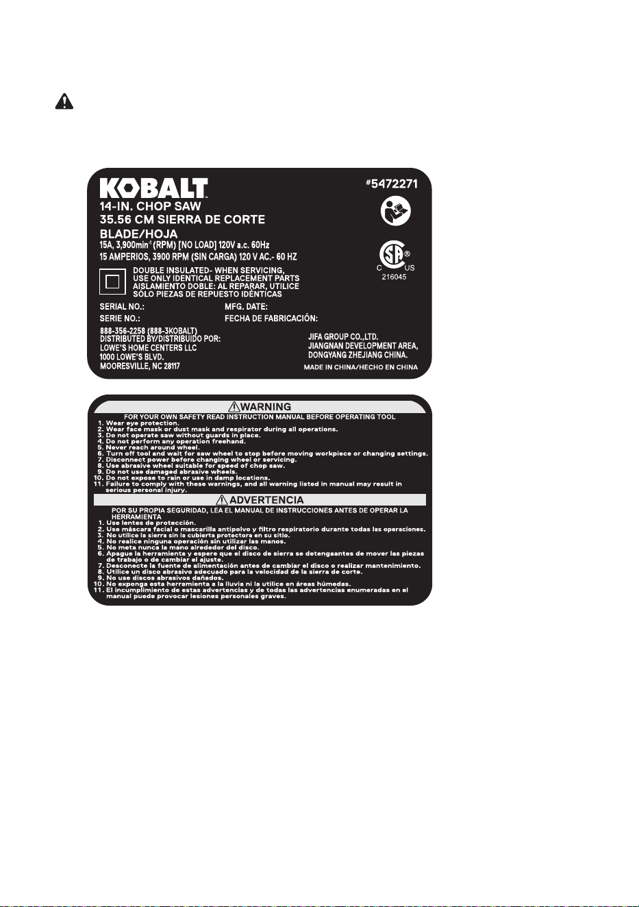
ITEM #5472271
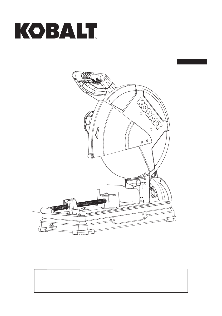
MODEL #CS3558LW
14-IN. CHOP SAW
35.56 CM SIERRA
DE CORTE
Español p. 29
Thank you for purchasing this KOBALT product.
Questions, problems or missing parts?
Before returning, contact us on:
888-356-2258, 8 a.m. - 8 p.m., EST, Monday - Sunday or [email protected].

2
TABLE OF CONTENTS
PRODUCT SPECIFICATIONS
Product Specications.............................................................................................................. 2
Package Contents..................................................................................................................... 3
Know Your Chop Saw............................................................................................................... 4
General Power Tool Safety Warnings....................................................................................... 5
Safety Instructions For Chop Saws.......................................................................................... 7
Electrical Safety Information..................................................................................................... 12
Preparation............................................................................................................................... 14
Assembly Instructions.................................................................................
......
........................ 15
Adjustment Instructions............................................................................................................. 17
Operating Instructions............................................................................................................... 20
Care And Maintenance.............................................................................................................. 22
Troubleshooting........................................................................................................................ 24
Replacement Parts List............................................................................................................ 25
Warranty.................................................................................................................................... 28
DESCRIPTION SPECIFICATIONS
Power Source
15A,120 V, 60 Hz
No Load Speed 3,900 RPM
Double Insulated
Yes
Diameter
14 in.
Arbor
1 in.
Cross cut 0°
Round
5 in.
Square 4-3/4 in. x 4-3/4 in.
Rectangular 4-1/2 in. x 6-1/2 in. / 3 in. x 9 in.
Miter cut 45°
Round 4 in.
Square 4 in. x 4 in.
Rectangular 3-11/32 in. x 5 in.
Vise clamp angle 0° - 45°
3
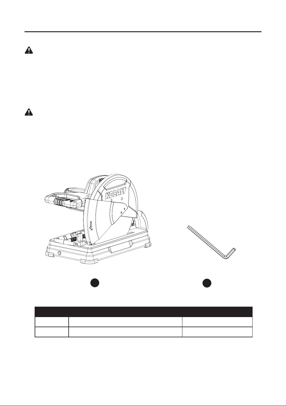
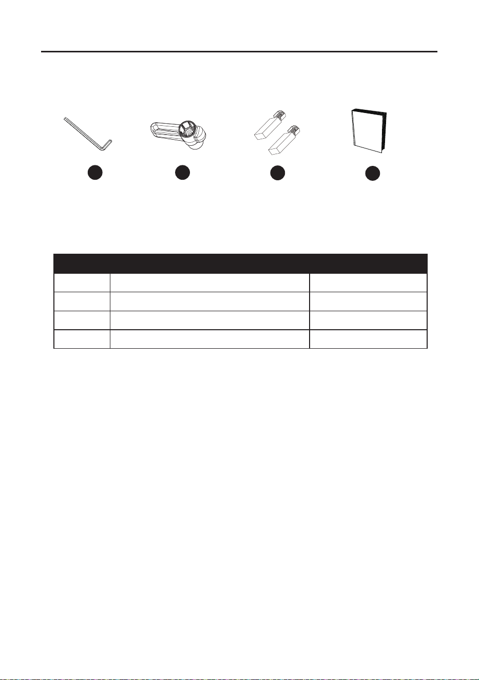
PACKAGE CONTENTS
PART DESCRIPTION QUANTITY
A Chop saw assembly 1
B Cutting wheel wrench (8 mm) 1
A
UNPACKING YOUR CHOP SAW
WARNING: To avoid injury from unexpected starting or electrical shock, do not plug the power
cord into a source of power during unpacking and assembly. The cord must remain unplugged
whenever you are adjusting/assembling the saw.
1. Remove the chop saw from the carton.
2. Place the saw on a secure and stationary work surface.
3. Separate all parts from the packing material. Check each one with the illustration below to
make certain all items are accounted for before discarding any packing material.
WARNING:
If any part is missing or damaged, do not attempt to assemble the chop saw or
plug in the power cord until the missing or damaged part is correctly replaced. To avoid electric
shock, use only identical replacement parts when servicing double-insulated tools.
B
4
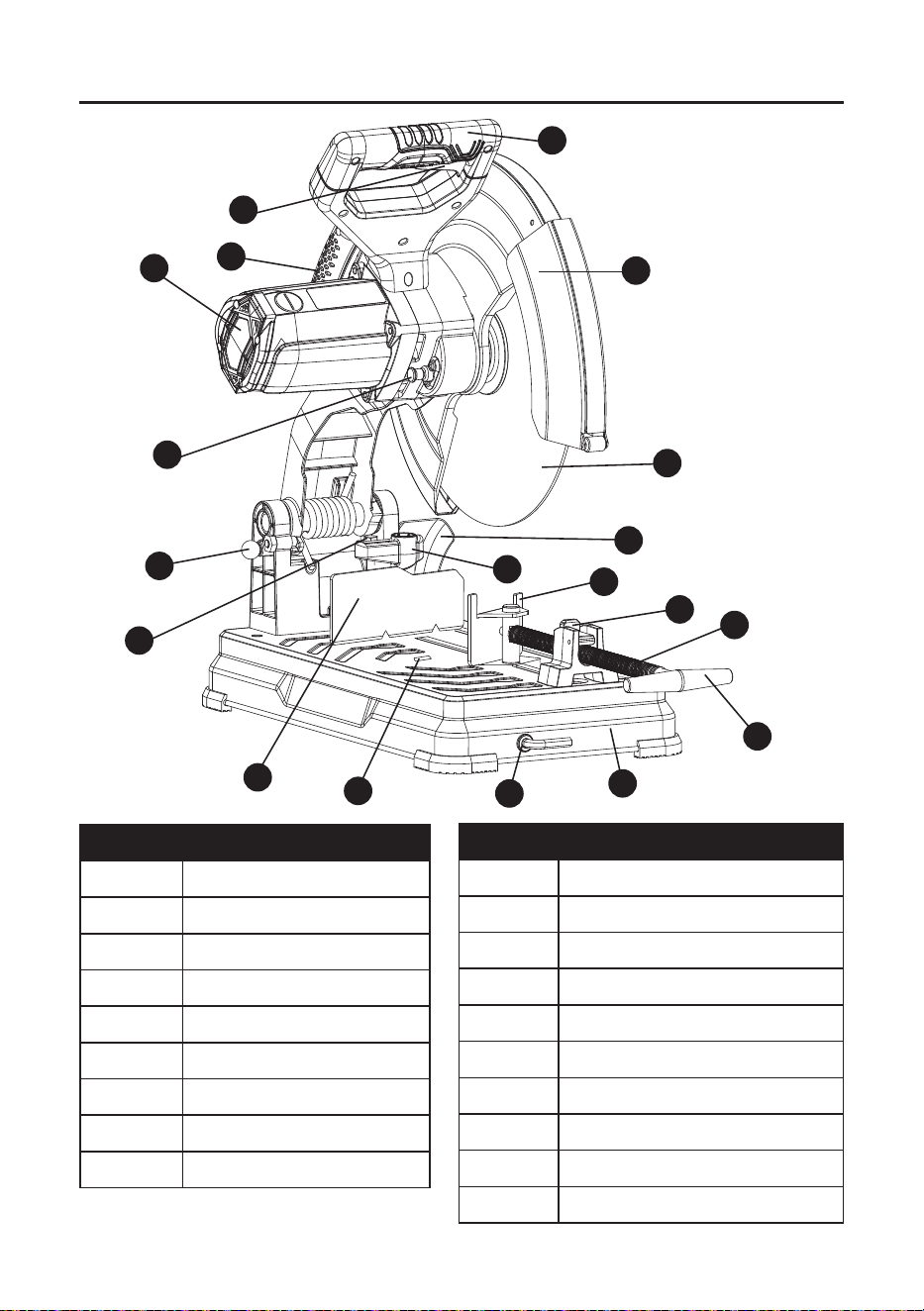
KNOW YOUR CHOP SAW
PART DESCRIPTION
C Switch handle
D Lower wheel guard
E Abrasive cutting wheel
F Spark Deector
G Fence lock knob
H Vise clamp
I Quick-release locking lever
J Vise
K Vise handle
PART DESCRIPTION
L Base
M Cutting wheel wrench & storage
N Fence
O Depth stop adjustment bolt
P Head lock down pin
Q Arbor lock button
R Motor
S Carrying handle
T Trigger switch
U Slot
C
D
E
G
F
H
I
J
K
L
M
N
O
P
Q
R
S
T
U

5
Read all safety warnings, instructions, illustrations and specications provided with this
power tool. Failure to follow all instructions listed below may result in electric shock, re and/or
serious injury.
Save all warnings and instructions for future reference.
The term "power tool" in the warnings refers to your mains-operated (corded) power tool or
battery-operated (cordless) power tool.
Work area safety
● Keep work area clean and well lit. Cluttered or dark areas invite accidents.
● Do not operate power tools in explosive atmospheres, such as in the presence of
ammable liquids, gases or dust. Power tools create sparks which may ignite the dust or
fumes.
● Keep children and bystanders away while operating a power tool. Distractions can cause
you to lose control.
Electrical safety
●
Power tool plugs must match the outlet. Never modify the plug in any way. Do not use
any adapter plugs with earthed (grounded) power tools. Unmodied plugs and matching
outlets will reduce risk of electric shock.
●
Avoid body contact with earthed or grounded surfaces, such as pipes, radiators,
ranges and refrigerators. There is an increased risk of electric shock if your body is earthed
or grounded.
●
Do not expose power tools to rain or wet conditions. Water entering a power tool will
increase the risk of electric shock.
●
Do not abuse the cord. Never use the cord for carrying, pulling or unplugging the power
tool. Keep cord away from heat, oil, sharp edges or moving parts. Damaged or entangled
cords increase the risk of electric shock.
●
When operating a power tool outdoors, use an extension cord suitable for outdoor use.
Use of a cord suitable for outdoor use reduces the risk of electric shock.
●
If operating a power tool in a damp location is unavoidable, use a residual current
device (RCD) protected supply. Use of an RCD reduces the risk of electric shock.
Personal safety
●
Stay alert, watch what you are doing and use common sense when operating a power
tool. Do not use a power tool while you are tired or under the inuence of drugs,
alcohol or medication. A moment of inattention while operating power tools may result in
serious personal injury.
●
Use personal protective equipment. Always wear eye protection. Protective equipment
such as dust mask, non-skid safety shoes, hard hat, or hearing protection used for appropriate
conditions will reduce personal injuries.
GENERAL POWER TOOL SAFETY WARNINGS
WARNING

6
●
Prevent unintentional starting. Ensure the switch is in the o-position before
connecting to power source and/or battery pack, picking up or carrying the tool.
Carrying power tools with your nger on the switch or energizing power tools that have the
switch on invites accidents.
●
Remove any adjusting key or wrench before turning the power tool on. A wrench or a
key left attached to a rotating part of the power tool may result in personal injury.
●
Do not overreach. Keep proper footing and balance at all times. This enables better
control of the power tool in unexpected situations.
●
Dress properly. Do not wear loose clothing or jewelry. Keep your hair, clothing and
gloves away from moving parts. Loose clothes, jewelry or long hair can be caught in moving
parts.
●
If devices are provided for the connection of dust extraction and collection facilities,
ensure these are connected and properly used. Use of dust collection can reduce dust-
related hazards.
●
Do not let familiarity gained from frequent use of tools allow you to become complacent
and ignore tool safety principles. A careless action can cause severe injury within a fraction
of a second.
Power tool use and care
●
Do not force the power tool. Use the correct power tool for your application. The correct
power tool will do the job better and safer at the rate for which it was designed.
●
Do not use the power tool if the switch does not turn it on and o. Any power tool that
cannot be controlled with the switch is dangerous and must be repaired.
●
Disconnect the plug from the power source and/or remove the battery pack, if
detachable, from the power tool before making any adjustments, changing accessories,
or storing power tools. Such preventive safety measures reduce the risk of starting the
power tool accidentally.
●
Store idle power tools out of the reach of children and do not allow persons unfamiliar
with the power tool or these instructions to operate the power tool. Power tools are
dangerous in the hands of untrained users.
●
Maintain power tools and accessories. Check for misalignment or binding of moving
parts, breakage of parts and any other condition that may aect the power tool’s
operation. If damaged, have the power tool repaired before use. Many accidents are
caused by poorly maintained power tools.
●
Keep cutting tools sharp and clean. Properly maintained cutting tools with sharp cutting
edges are less likely to bind and are easier to control.
●
Use the power tool, accessories and tool bits etc. in accordance with these instructions,
taking into account the working conditions and the work to be performed. Use of the
power tool for operations dierent from those intended could result in a hazardous situation.
●
Keep handles and grasping surfaces dry, clean and free from oil and grease. Slippery
handles and grasping surfaces do not allow for safe handling and control of the tool in
unexpected situations.
Service
●
Have your power tool serviced by a qualied repair person using only identical
replacement parts. This will ensure that the safety of the power tool is maintained.

7
SAFETY INSTRUCTIONS FOR CHOP SAWS
BEFORE USING THE CHOP SAW, IT IS CRITICAL THAT YOU READ AND UNDERSTAND
THESE SAFETY RULES.
WARNING: To avoid mistakes that could cause serious or permanent injury, do not plug the
chop saw until the following instructions have been read and understood.
● Learn the function of the ON/OFF switch, cutting handle and wheel guard.
●
Review and understand all safety instructions and operating procedures in this Operator’s manual.
● Review the maintenance methods for this chop saw.
● Find and read all the warning labels on the chop saw:
● Read manual before using the chop saw.
● Wear safety goggles.
● Never perform cutting operations with wheel guard removed.
●
Turn power OFF, wait for abrasive wheel to stop and remove power cord from power source
before adjusting or servicing.
● The arbor bolt and all clamps have to be tightened before cutting.
● Make sure the workpiece and the abrasive wheel are not in contact prior to operating the saw.
WHEN INSTALLING OR MOVING YOUR CHOP SAW:
● Avoid a dangerous environment:
● Use the chop saw in a dry, indoor location protected from rain and moisture.
● Keep work area well lit.
● To avoid injury from unexpected chop saw movement:
●
Bolt or clamp the chop saw to a rm level surface where there is plenty of room to move the
workpiece through the entire cut.
● Position the chop saw so the feet are level and the chop saw does not rock.
● Position the chop saw where operators and bystanders stand a safe distance away from
the saw and are not in direct line with the cutting wheel.
● To avoid injury from electrical shock, make sure your ngers do not touch the plug’s metal
prongs when plugging in or unplugging the chop saw.
● Turn OFF and unplug the chop saw before moving it to a new area. To avoid back injury,
get help when transporting.
● Bolt the chop saw to the oor if it tends to move when cutting long, heavy workpieces.
● DO NOT STAND ON the chop saw. Do not store materials above or near it. Standing on
the tool could result in serious injury.
BEFORE EACH USE
● Inspect your chop saw:
● If any part is missing, bent or broken in any way, or any electrical part does not work
properly, turn the chop saw OFF and unplug the tool.
● Replace damaged or missing parts before using the chop saw.
● Avoid injury from jams, slips or thrown pieces (kickbacks):
● Use this chop saw to cut ferrous material only.
● Avoid injury from thrown pieces. Make sure the abrasive wheel is properly installed and
the arbor bolt is tight.
● Use the right tool. Do not force the tool to do a job it is not intended to do.

8
● Inspect your work area:
● Keep the work area clean.
● Cluttered areas and benches invite accidents. The oor must not be slippery from wax,
sawdust or shavings, etc.
● Avoid burns or other re damage. Do not use the
chop
saw near ammable liquids, vapors
or gases.
● Before using the
chop
saw, clear the table of all objects not needed to feed the workpiece.
● Avoid injury. Do not perform layout, assembly or setup on the
chop
saw.
● Never hold a workpiece. Workpiece will become very hot while being cut.
●
Plan your work:
●
Before trying a new or not often used operation, carefully plan your hand placement. Make sure
you have proper xtures, stops and other items ready to use. Avoid injury form unsafe
accessories. Use only recommended accessories.
●
Dress for safety:
● Plan ahead to protect your eyes, hands, face and ears.
● Do not wear loose clothing, gloves, neckties or jewelry (rings, wrist watches). They can
get caught and draw you into moving parts.
● Wear non-slip footwear.
● Tie back long hair.
● Roll long sleeves above the elbow.
●
Noise levels vary widely. To avoid possible hearing damage, wear ear plugs or mus when
using the chop saw.
● The chop saw can throw debris into your eyes which can result in permanent eye damage.
Wear safety goggles (not glasses) that comply with ANSI Standards. Regular eyeglasses
have only impact-resistant lenses. They are not safety glasses.
● Wear a dust mask along with safety goggles during each operation.
● Inspect your workpiece:
● Make sure there are no bolts or foreign objects in the part of the workpiece to be cut.
● Plan your cut:
● Do not cut freehand. Guide your workpiece solidly against the fence and table top. Make
sure there is no debris between the workpiece and its supports.
● Use extra caution with large, small or awkward workpieces.
● Use extra support (tables, sawhorses, blocks) if your workpiece is hard to hold down to
the table. Do not use another person as additional support or to help feed, support or pull
the workpiece.
● Do not cut more than one workpiece at a time.
● Do not turn your chop saw ON before clearing everything except the workpiece and related
support devices o the table.
● Avoid accidental starting:
● Make sure the switch is o before plugging the abrasive chop saw into a power source.
WHEN THE CHOP SAW IS RUNNING
WARNING: Do not allow familiarity gained from frequent use of your chop saw to cause a
careless mistake. remember that a careless fraction of a second is enough to cause a severe
injury.
● Keep children away:
● Make sure all bystanders are clear of the power tool before and during use.

9
● Before using the power tool, test the saw by turning it on and letting it run for a few sec-
onds. If it makes an unfamiliar noise or vibrates, stop immediately. Turn the chop saw o
and unplug. Do not restart the tool until the problem has been corrected.
● Do not force the tool:
● Only cut one piece per cutting operation.
●
Before freeing jammed material:
● Release the trigger switch.
●
Wait for all moving parts to stop.
● Unplug the chop saw.
● Before leaving the chop saw:
● Release the trigger switch.
● Unplug the chop saw.
● Make the workshop childproof. Lock the shop. Disconnect master switches.
WARNING
●
A 14 in. wheel is the maximum wheel capacity of your chop saw. Never use a wheel that is too
thick to allow outer ange to engage with the ats on the spindle. Larger wheels will come in
contact with the wheel guards, while thicker wheels will prevent the bolt from securing the wheel
on the spindle. Either of these situations could result in a serious accident causing personal injury.
● Do not attempt to cut wood or masonry with this chop saw. Never cut magnesium or magnesium
alloy with this machine. Failure to comply could result in serious personal injury.
● To prevent chop saw movement or tipping during cutting procedure, secure the chop saw to a
workbench or work surface that is also secure.
● Always use the vise on the chop saw to prevent accidents that could result in serious
personal injury.
● Never stand or have any part of your body in line with the path of the wheel. Doing so may
cause an accident resulting in serious personal injury.
Large, circular or irregularly shaped workpieces may require additional clamping in order to
be properly secured for cutting. Use “C” clamps that can be mounted along the left and front
side of the machine base. Also use blocks to hold material securely. Failure to comply could
result in serious personal injury.
● Use only correct wheels. Do not use wheels with incorrect size holes. Never use wheel
washers or wheel screws that are defective or incorrect. The maximum wheel capacity of your
chop saw is 14 inches.
● Do not remove the chop saw’s wheel guards. Never operate the chop saw with any guard
or cover removed. Make sure all guards are operating properly before each use.
●
Keep hands away from cutting area. Keep hands away from wheel. Do not reach underneath
work or around or under the wheel while the wheel is rotating. Do not attempt to remove cut
material while wheel is moving.
● Never use in an explosive atmosphere. Normal sparking of the motor or sparking from
cutting metal could ignite fumes.
● Do not use tool if switch does not turn it on and o. Have defective switch replaced by an
authorized service center.
WARNING

10
● Keep tool dry, clean and free from oil and grease. Always use a clean cloth when cleaning.
Never use brake uids, gasoline, petroleum-based products or any solvents to clean tool.
● Always support long workpieces. To minimize risk of tipping the saw, always support long
workpieces.
● Before making a cut, be sure all adjustments are secure. Always use the vise clamp to
secure the workpiece.
● Never touch wheel or other moving parts during use.
● Never start the chop saw when the wheel is in contact with the workpiece.
● Never cut more than one workpiece at a time.
● Do not stack more than one workpiece on the machine base at a time.
● Never perform any operation free-hand. Always secure the workpiece to be cut in the vise.
● Never hand hold a workpiece. Workpiece will become very hot while being cut.
● Never reach behind, under or within 3 in. of the wheel and its cutting path with your hands and
ngers for any reason.
● Never reach to pick up a workpiece, a piece of scrap or anything else that is in or near the
cutting path of the wheel.
● Make sure the wheel is securely mounted as described in the operating instructions before
connecting the tool to a power supply. Do not tighten wheel excessively, since this can cause
cracks.
● Check the wheel for ssures and cracks, and test for normal operation prior to use.
●
Always ease the abrasive wheel against the workpiece when starting to cut. A harsh impact
can break the wheel.
● Only use a chop saw wheel rated for 3900 rpm or greater and manufactured in compliance
with ANSI B 7.1. Always store wheels in a dry place with little temperature variation.
● Before cutting, press the trigger switch and allow the wheel to reach full speed.
● This chop saw has been designed for cutting metals using reinforced abrasive chop
saw wheels only. Do not remove the wheel, install a steel blade and attempt to cut other
types of materials such as wood, masonry, etc. Attempting to cut these other types of
materials could cause an accident resulting in serious personal injury.
● Do not attempt to modify this tool or create accessories not recommended for use with
this tool. Any such alteration or modication is misuse and could result in a hazardous
condition leading to serious personal injury.

11
PROPOSITION 65 WARNING
Some dust created by power sanding, sawing, grinding, drilling, and other construction activities
contains chemicals known to the State of California to cause cancer, birth defects or other
reproductive harm. Some examples of these chemicals are:
● Lead from lead-based paints,
● Crystalline silica from bricks and cement and other masonry products, and
● Arsenic and chromium from chemically treated lumber.
Your risk from these exposures varies depending on how often you do this type of work. To reduce
your exposure to these chemicals: work in a well-ventilated area and work with approved safety
equipment, such as dust masks that are specially designed to lter out microscopic particles.
Handling the power cord on this product may expose you to chemicals known to the state of
California to cause cancer and birth defects or other reproductive harm. Wash hands after handling.
For more information go to: www.P65Warnings.ca.gov
READ INSTRUCTION MANUAL: To reduce the risk of injury, user and all bystanders
must read instruction manual before using this product.
WARNING
12
ELECTRICAL SAFETY INFORMATION
ELECTRICAL SPECIFICATIONS AND SAFETY
POWER SUPPLY AND MOTOR
The A/C motor used in this saw is a universal, nonreversible type. See “MOTOR” in the
“PRODUCT SPECIFICATIONS” section on page 2.
To avoid electrical hazards, re hazards or damage to the tool, use proper circuit
protection. Your saw is wired at the factory for 120 V operation. Connect to a 120 V, 15 A
circuit and use a 20 A time-delay fuse or circuit breaker. If power cord is worn or cut or
damaged in any way, have it replaced immediately to avoid shock or re.
DOUBLE INSULATED (Symbol: )
This power tool is double insulated to provide a double thickness of insulation between you and
the tool’s electrical system. All exposed metal parts are isolated from the internal metal motor
components with protective insulation.
REPLACEMENT PARTS – When servicing, use only identical replacement parts. Refer to the
Replacement Parts List on the page 25.
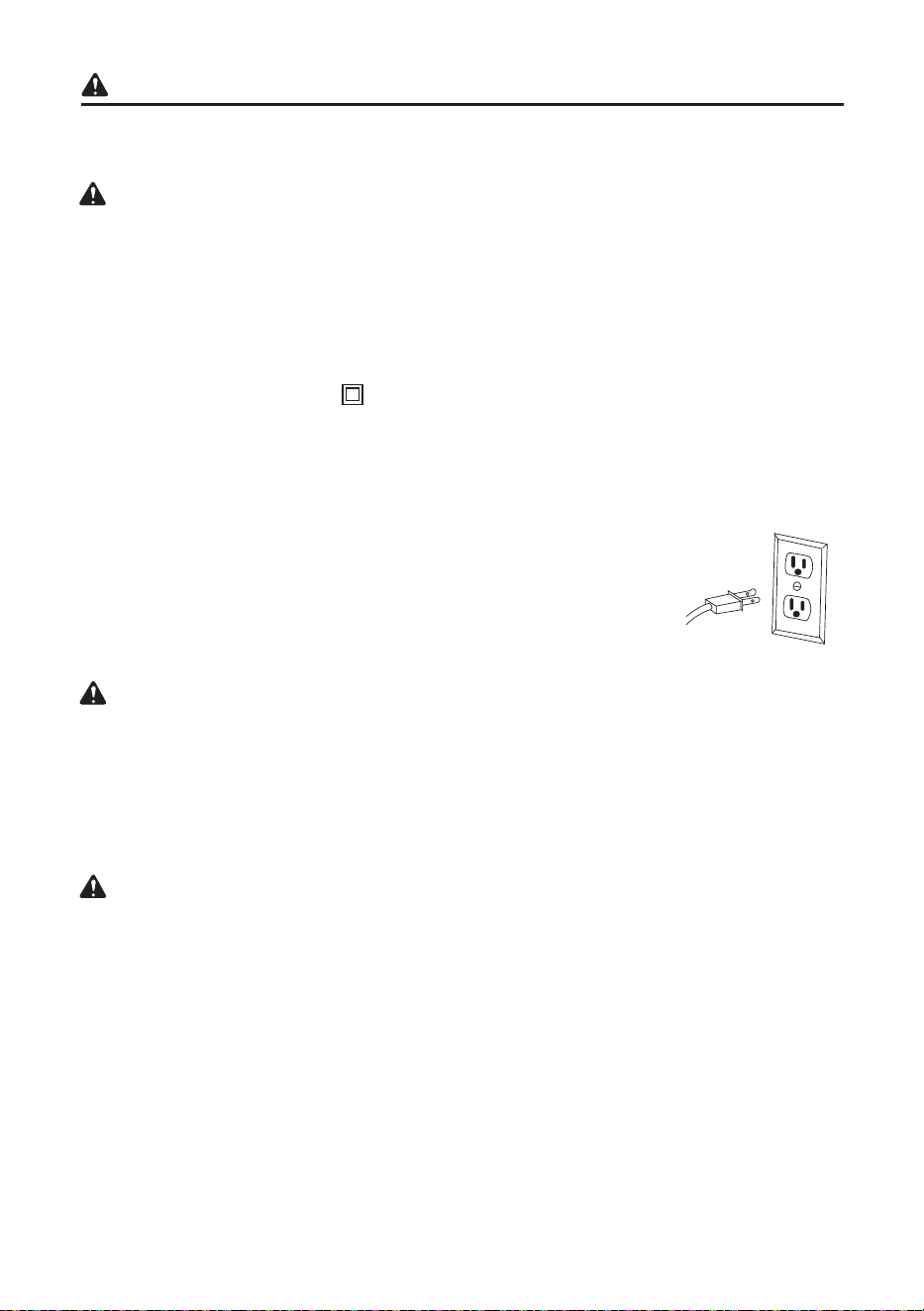
POLARIZED PLUGS – To reduce the risk of electrical shock, this saw has
a polarized plug (one blade is wider than the other). This plug (illustrated at
right) will t in a polarized outlet only one way. If the plug does not t fully in
the outlet, reverse the plug. If it still does not t, contact a qualied electrician
to install the proper outlet. Do not change the plug in any way.
Double insulation does not take the place of normal safety precautions when operating this
tool. To avoid electrocution:
● Use only identical replacement parts when servicing a tool with double insulation. Servicing
should be performed by a qualied technician.
● Do not use power tools in wet or damp locations or expose them to rain or snow.
MOTOR SAFETY PROTECTION
To avoid motor damage, the motor should be blown out or vacuumed frequently to keep sawdust
from interfering with motor ventilation.
● CONNECT this saw to a 120 V, 15 A circuit with a 20 A time-delay fuse or circuit breaker.
Using the wrong size fuse can damage the motor.
● If the motor will not start, release the trigger switch immediately. UNPLUG THE SAW. Check
the saw blade to make sure it turns freely. If the blade is free, try to start the saw again. If the
motor still does not start, refer to TROUBLESHOOTING.
● If the tool suddenly stalls while cutting wood, release the trigger switch, unplug the tool and
free the blade from the wood. The saw may now be started and the cut nished.
CAUTION
CAUTION
CAUTION
13
Be sure your extension cord is properly wired and in good condition. Always replace a
damaged extension cord or have it repaired by a qualied person before using it. Protect your
extension cords from sharp objects, excessive heat and damp or wet areas.
Use a separate electrical circuit for your tools. This circuit must not be less than #12 wire and
should be protected with a 20 A time-delay fuse or circuit breaker. Before connecting the tool to
the extension cord, make sure the saw switch is in the OFF position. The electric circuit should be
rated at the same voltage as is stamped on the motor nameplate. Running at a lower voltage will
damage the motor.
In all cases make certain the receptacle in question is properly grounded. If you are not sure, have
a certied electrician check the receptacle.
● FUSES may “blow” or circuit breakers may trip frequently if:
- MOTOR is overloaded – overloading can occur if you feed too rapidly or make too many
starts/stops in a short time.
- LINE VOLTAGE is more than 10% above or below the nameplate voltage rating. For heavy
loads, the voltage at motor terminals must equal the voltage specied on the nameplate.
- IMPROPER or dull saw blades are used.
GUIDELINES FOR EXTENSION CORDS
When using an extension cord, be sure to use one heavy enough to carry the current your
product will draw. An undersized cord will cause a drop in line voltage, resulting in loss of power
and overheating. The table below shows the correct size to use depending on cord length and
nameplate ampere rating. If in doubt, use the next heavier gauge. The smaller the gauge number,
the heavier the cord.
MINIMUM GAUGE FOR EXTENSION CORDS (AWG)
(When using 120 volts only)
Ampere Rating Total length of Cord
More Than Not More Than 25 ft. 50 ft. 100 ft. 150 ft.
0 6 18 16 16 14
6 10 18 16 14 12
10 12 16 16 14 12
12 16 14 12 Not Recommended
CAUTION

14
Before beginning assembly or operation of the product, make sure all parts are present. Compare
parts with package contents list and diagram on page 3. If any part is missing or damaged, do not
attempt to assemble, install or operate the product.
Estimated Assembly Time: 5 minutes.
Tools needed to remove or install blade (included): 8 mm Hex Wrench.
Tools Required for Adjustment (not included): 10 mm Hex Wrench, 5 mm Hex Wrench, Square,
Phillips Screwdriver, Slotted Screwdriver.
PREPARATION
15
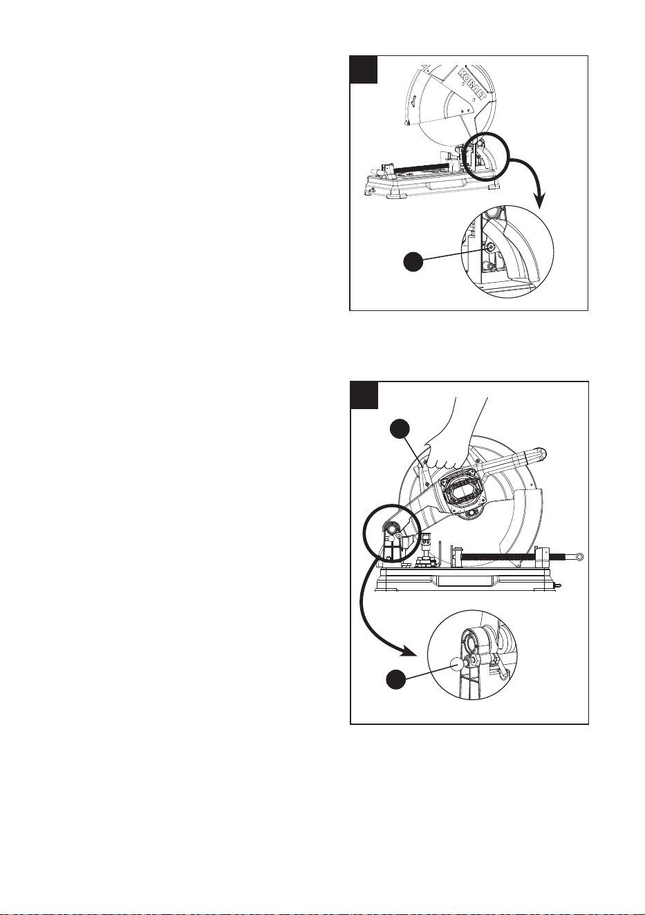
1
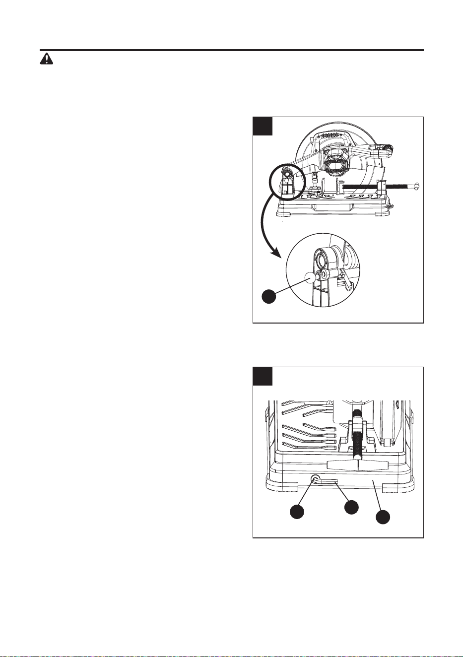
ASSEMBLY INSTRUCTIONS
WARNING: To avoid injury, do not connect
this chop saw to a power source until it is
completely assembled and you have read
and understood the instruction manual.
RAISING AND LOCKING THE CUTTING HEAD
(FIG. 1)
NOTE: The cutting head must be locked in the
down position for transporting and storing the
chop saw.
● To raise, press the cutting head down slightly
and pull out the head lock down pin (P).
● To lock, press the cutting head down slightly
and push in the head lock down pin (P).
STORING THE CUTTING WHEEL WRENCH
(FIG. 2)
When you are not using the cutting wheel
wrench (B), the cutting wheel wrench storage (M)
is located in the front of the saw base (L).
2
M
B
P
L
16
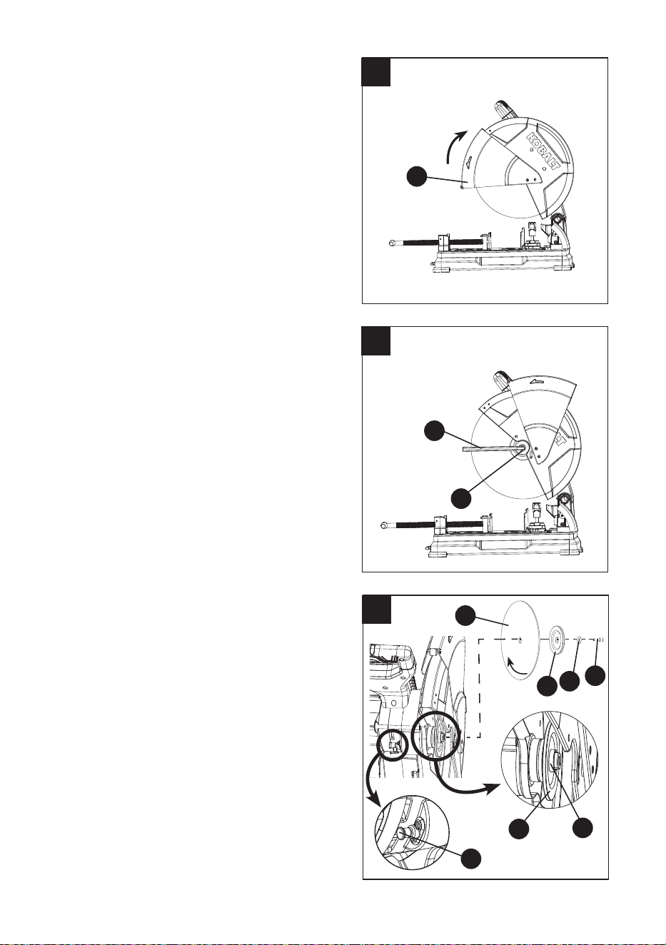
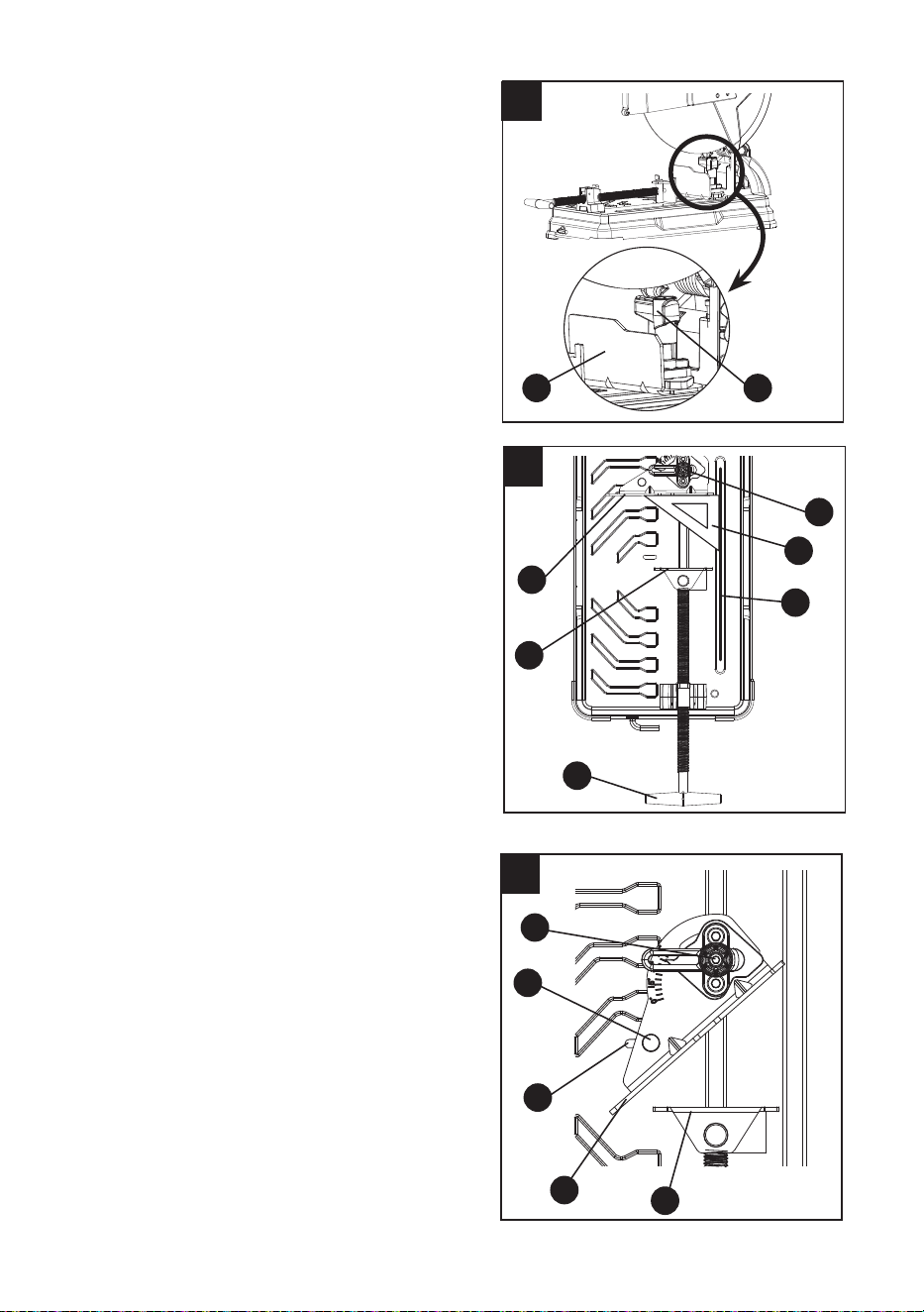
REMOVING THE ABRASIVE CUTTING WHEEL
(FIG. 3, 4, 5)
NOTE: Use only recommended reinforced
abrasive wheels (rated 3900 RPM or greater).
● Unplug the tool.
● Raise the cutting head to the upward positon.
● Raise the lower wheel guard (D) to the
uppermost position to expose the arbor
bolt (1). (Fig. 3, 4)
● Place the cutting wheel wrench (B) over the
arbor bolt (1). (Fig. 4)
● Push in the arbor lock button (P-Fig.5)
and then loosen the arbor bolt (1)
counterclockwise with the cutting wheel
wrench (B) provided.
● Remove the arbor bolt (1), the washer (2),
the outer wheel collar (3) and the abrasive
cutting wheel (E). (Fig. 5)
NOTE: Do not remove the inner washer (4)
and the inner wheel collar (5).
INSTALLING THE ABRASIVE CUTTING
WHEEL (FIG. 3, 4, 5)
NOTE: Inspect wheel before mounting that it is
in good shape, no chipping or cracking.
● Unplug the tool.
● Install the new abrasive cutting wheel (E)
followed by the outer wheel collar (3), the
washer (2) and the arbor bolt (1). (Fig. 5)
NOTE: Make sure the directional arrow on
the replacement wheel matches the direction
of the saw.
● Push in the arbor lock button (Q).
● Turn the arbor bolt (1) clockwise until snug
and tighten with the cutting wheel wrench (B)
provided. (Fig. 4)
● Be sure the arbor lock button (Q) is released
so the abrasive cutting wheel (E) turns freely
by spinning the cutting wheel while the arbor
lock button (Q) disengages.
● Release the lower wheel guard (D) back to
its original position. (Fig. 3)
NOTE: If the cutting depth stop bolt has been
adjusted during operation of the old abrasive
wheel, reset for the depth for a new 14 in.
abrasive wheel. (See instructions on page 17)
3
4
5
D
1
B
1
2
3
E
4
5
Do not remove
Q
17
ADJUSTMENT INSTRUCTIONS
WARNING: To avoid injury, do not connect
this chop saw to a power source when
making any adjustments.
ADJUSTING THE CUTTING DEPTH STOP
BOLT (FIG. 6)
NOTE: The cutting depth was adjusted properly
at the factory. If adjustments are needed, be
careful not to adjust the depth stop bolt too deep,
as the cutting wheel may contact the base.
● Loosen the lock nut (1) with a 10 mm hex
wrench.
● Turn the depth stop adjustment bolt (O) with
a 5 mm hex wrench counterclockwise to
decrease the cutting depth or clockwise to
inscrease the cutting depth.
● Lower the cutting head to check that the
wheel does not contact the base.
● Repeat until adjusted properly and tighten
the lock nut (1).
6
1
O
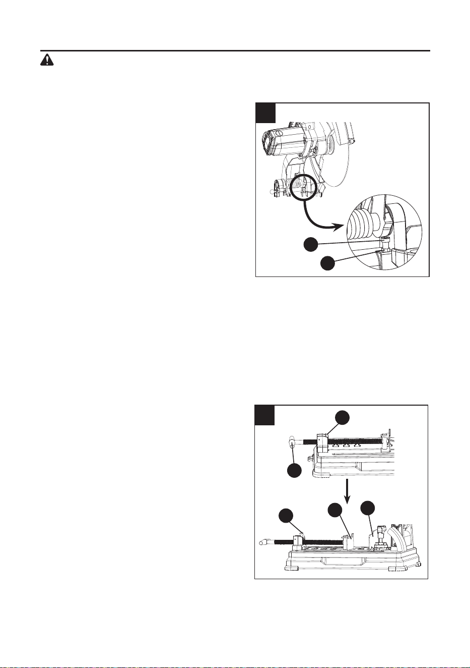
ADJUSTING THE VISE (FIG. 7)
NOTE: The vise of your saw is used to secure
the workpiece during cutting operations.
● Rotate the vise handle (K) counterclockwise
to allow enough room for the workpiece to
t between the vise clamp (H) and the
fence (N).
● Position the workpiece between the vise
clamp (H) and the fence (N). Rotate the vise
handle (K) clockwise to clamp the workpiece
securely.
● The vise incorporates a quick-release locking
lever (I). To use the quick-release feature, lift
up on the quick-release locking lever (I) and
hold the vise handle to move backward or
forward to the desired position.
NOTE:
● To maintain this adjustment, the lock nut (1) on the depth stop adjustment bolt (O) must be
tightened securely.
● The depth stop is factory set providing maximum cutting capacity for the 14 in. abrasive cutting
wheel provided with your chop saw. When the diameter of the wheel has reduced in size due
to normal wear, the depth stop adjustment bolt may require adjustment to provide maximum
cutting capacity.
● When a replacement wheel is installed onto the unit, it is necessary to check the clearance of
the cutting wheel to the machine base before operating.
7
H
I
K
N
I
● When the vise clamp (H) is in desired location, ip the quick-release locking lever (I) down to
engage the threads with the threads of the vise. Rotate the vise handle (K) clockwise to clamp
the workpiece securely.
18
ADJUSTING THE FENCE (FIG. 8)
The fence can be moved backward or forward
and adjusted to any angle between 0°~45°. No
tools are required.
● Loosen the fence lock knob (G) by turning it
180 degrees counterclockwise.
● Move the fence (N) to the desired position.
● Tighten the fence lock knob (G) by turning it
180 degrees clockwise.
ADJUSTING FENCE SQUARENESS (FIG. 9)
● Loosen the vise handle (K) and pull back the
vise clamp (H) from the fence (N).
● Loosen the fence lock knob (G) by turning it
180 degrees counterclockwise.
● Lower the cutting head down until the
abrasive cutting wheel (E) is below the base.
● Place a square (1) against the abrasive
cutting wheel (E) and adjust the fence
against the square.
● Adjust the fence 90° to the abrasive cutting
wheel (E) and tighten the fence lock knob (G)
by turning it 180 degrees clockwise.
NOTE: If the saw has not been used recently,
recheck abrasive cutting wheel squareness
to the fence and readjust if needed.
● Raise the cutting head up to its position
when alignment is achieved.
8
GN
ADJUSTING THE CUTTING ANGLE (FIG. 9, 10)
● Loosen the vise handle (K-Fig. 9) and pull back
the vise clamp (H) from the fence (N).
● Loosen the fence lock knob (G) by turning it
180 degrees counterclockwise.
● Move the fence (N) to the desired angle
between 0 and 45 degrees.
● Tighten the fence lock knob (G) by turning it
180 degrees clockwise.
● For the 45 degrees, unlock the fence lock
knob (G) turn the fence to 45 degrees, then
move the fence (N) forward until the pin (1)
clicks into the slot (U) located on the base.
● Tighten the fence lock knob (G) by turning it
180 degrees clockwise.
NOTE: To re-locate the fence (N) pull the pin (1)
up and move the fence to the desired position and
angle .
10
1
U
H
G
N
9
G
N
H
1
E
K
19
ADJUSTING THE SPARK DEFLECTOR (FIG. 11)
The spark deector allows for the sparks caused
during operation to be directed away from the
workpiece and surrounding people.
● To adjust the spark deector for the
maximum eect, loosen the screw (1) by
using a phillips screwdriver, adjust the spark
deector to the required angle and then
retighten the screw.
CAUTION: Risk of property damage, DO NOT
allow power cord to come into contact with spark
deector or sparks as damage to power cord
may occur.
CARRYING THE CHOP SAW (FIG. 12)
The chop saw can be transported to any
workplace conveniently by:
● Lowering the cutting head to its lowest
position and push in the head lock down
pin (P).
● Transport the chop saw using the carrying
handle (S) located above the motor.
12
S
P
11
1
20
OPERATING INSTRUCTIONS
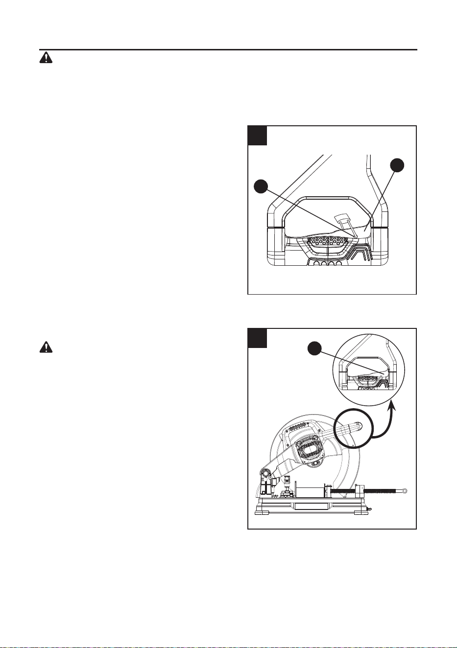
TURNING THE SAW ON (FIG. 13)
Squeeze the trigger switch (T) to turn the
chop saw ON.
NOTE: Insert a padlock (not included) through
the hole (1) in the trigger switch, locking the
tool’s switch and preventing children and other
unauthorized users from turning the machine on.
CUTTING THE WORKPIECE (FIG. 14)
Failure to heed the safety rules could result
in serious personal injury:
● To avoid serious personal injury, always
make sure the fence is secured in position.
●
Never perform any cutting operation freehand
(without placing workpiece in the vise).
● Material will get hot during cutting operations.
Keep hands o of metal being cut to avoid
serious personal injury.
● Do not touch the cut material until it cools or
you can be burned.
● Never stand or have any part of your body in
line with the path of the wheel.
● Inspect the abrasive cutting wheel before
every operation. Check for cracks, chipping
and correct speed ratings on the cutting
wheel.
13
14
WARNING
WARNING: Never connect the plug to the
power source outlet until all adjustments
are completed and you have read and
understood the safety and operational
instructions.
T
T
1

21
● When the cut is complete, release the
trigger switch (T) and allow the wheel to
stop rotating before raising the cutting
head out of the workpiece.
Do not attempt to cut wood or masonry with
this chop saw. Never cut magnesium or
magnesium alloy with this chop saw. Failure
to comply could result in serious personal
injury.
● Place the workpiece at on the base.
● Firmly secure the workpiece to be cut using
the vise.
● When cutting long workpiece, support the
opposite end of the workpiece with a roller
stand or with a work surface level with the
saw.
● Before turning the saw on, perform a dry run
of the cutting operation to verify no problems
will occur when the cut is made.
● Turn on the saw by depressing the trigger
switch (T). Allow a few seconds for the wheel
to build up to full speed before letting it come
into contact with the workpiece.
● Once the motor has reached full speed,
slowly lower the cutting head until the cutting
wheel contacts the workpiece. Coutinue
to use steady, even pressure to obtain a
uniform cut through the workpiece. Do not
force the cutting wheel into the workpiece.
WARNING
22
CARE AND MAINTENANCE
WARNING: Never put lubricants on the
abrasive cutting wheel while it is spinning.
To avoid re or toxic reaction, never use
gasoline, naphtha acetone, lacquer thinner
or similar highly volatile solvents to clean the
chop saw. To avoid injury from unexpected
starting or electrical shock, unplug the
power cord before working on the tool. To
avoid electrical shock, re or injury, use
only parts identical to those identied in the
parts list. Reassemble exactly as the original
assembly to avoid electrical shock.
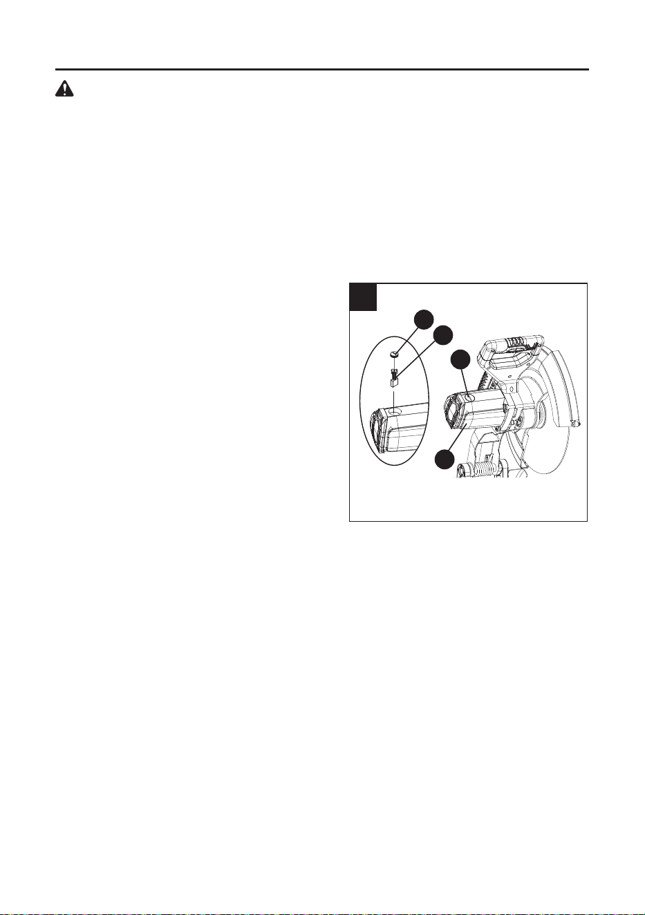
REPLACING CARBON BRUSHES (FIG. 15)
NOTE: Before replacing carbon brushes, make
sure the chop saw has been disconnected from
the power source.
Replace both carbon brushes when either has
less than 1/4 in. length of carbon remaining, or if
the spring or wire is damaged or burned.
● To insert or replace brushes, rst unplug the
tool. Remove the black plastic cap (1) on the
side of the motor (R) using a slotted
screwdriver.
NOTE: The brush assembly (U) has a spring,
so the cap (1) may pop out when loosened.
● Pull out the brush assembly (U) and replace
with the new one, if needed. The ears on the
metal end of the assembly go in the same
slots the carbon part ts into. Tighten the cap
snugly, but do not overtighten. Repeat for the
other side.
15
NOTE: To reinstall the same brushes, rst make sure the brushes go back in the way they came
out. This will avoid a break-in period that reduces motor performance and increases wear.
LUBRICATION
Motor and cutterhead bearings are sealed and need NO lubrication.
CLEANING
Keep your chop saw clean. Continually remove metal chips, dust, dirt and debris.
R
1
1
U
23
WARNING
FREE WARNING LABEL REPLACEMENT:
If your warning labels become illegible or are missing, call for a free replacement.
DO NOT replace the power cord. If you have any problem or questions concerning the power
cord, call the Customer Service Department at 888-356-2258.

24
To avoid injury from accidental starting, always ensure switch is in the OFF position and unplug
the tool before moving, replacing the blade or making adjustments
.
PROBLEM POSSIBLE CAUSE CORRECTIVE ACTION
Chop saw
wheel hits
base or work
surface.
1. The cutting depth adjustment bolt
is set too deep.
1. See “Adjusting the Cutting Depth Stop
Bolt” section.
Cutting wheel
does not
cut through
workpiece.
1. Depth stop bolt setting is
incorrect.
1. See “Adjusting the Cutting Depth Stop
Bolt” section.
Cut is not
square.
1. Defective wheel.
2. Work not positioned properly.
3. Excessive wheel pressure.
1. Replace immediately.
2. See “Adjusting the Angle Cutting”
section.
3. Lessen wheel pressure during cutting
operation.
Chop saw
wheel binds,
jams, burns
workpiece.
Rough cuts.
1. Improper operation.
2. Dull chop saw wheel.
3. Improper chop saw wheel.
1. See “Operation” section.
2. Replace wheel.
3. Replace with 14 in. abrasive cutting
wheel.
Tool vibrates or
shakes.
1. Wheel not round.
2. Wheel damaged.
3. Wheel loose.
4. Machine is not secure.
5. Other.
1. Replace wheel.
2. Replace wheel.
3. Tighten arbor bolt.
4. Mount tool to worksurface.
5. Contact customer service.
Power head
won’t fully rise.
1. Pivot spring not replaced properly
after service.
2. Part failure.
1. Contact customer service.
2. Contact customer service.
TROUBLESHOOTING
WARNING
25
REPLACEMENT PARTS LIST
For replacement parts, call our customer service department at 888-3KOBALT (888-356-2258),
8 a.m. - 8 p.m., EST, Monday - Sunday. You could also contact us at [email protected].
PART DESCRIPTION PART#
B Cutting wheel wrench X8GK
G Fence lock knob X8GJ
U Carbon brushes (set of 2) X8GH
V Manual X8GG
DISTRIBUTED BY:
Lowe’s Home Centers LLC
1000 Lowe’s Blvd., Mooresville, NC 28117
B
U
V
G

26
PAGE INTENTIONALLY LEFT BLANK

27
PAGE INTENTIONALLY LEFT BLANK

28
Printed in China
The manufacturer will oer replacement parts for this product which under normal usage have
proven to be defective in their manufacture or workmanship for a period of THREE (3) years from
the date of initial retail purchase. This warranty is valid only to the original purchaser. This warranty
is not transferable and does not cover any parts that have been subjected to misuse, abuse,
alteration, overload, accident or normal wear of moving parts. Tools that have been sold “as is,”
sold reconditioned or used as rental equipment are not covered.
Warranty replacement parts can be obtained by contacting the manufacturer at 888-3KOBALT.
Only the manufacturer is authorized to perform warranty service on this product. This warranty
does not apply to accessories or damage caused where repairs have been made or attempted
by others.
The manufacturer is not responsible for direct, indirect, incidental or consequential damages.
Some states do not allow limitations on how long an implied warranty lasts and/or do not allow the
exclusion or limitation of incidental damages, so the above limitations may not apply to you. This
warranty gives you specic legal rights, and you may also have other rights, which vary from state
to state.
The manufacturer makes no warranties, representations or promises as to the quality of its power
tools other than those specially stated in this warranty.
WARRANTY VOID IF PRODUCT USED FOR COMMERICAL PURPOSES.
For replacement parts, call our customer service department at 888-3KOBALT (888-356-2258).
WARRANTY
