
Service Manual
E23584
First Edition / November 2024

2
Service Manual
COPYRIGHT INFORMATION
No part of this manual, including the products and software described in it, may be reproduced,
transmitted, transcribed, stored in a retrieval system, or translated into any language in any form or by
any means, except documentation kept by the purchaser for backup purposes, without the express
written permission of ASUSTeK COMPUTER INC. (“ASUS”).
ASUS PROVIDES THIS MANUAL “AS IS” WITHOUT WARRANTY OF ANY KIND, EITHER EXPRESS OR IMPLIED,
INCLUDING BUT NOT LIMITED TO THE IMPLIED WARRANTIES OR CONDITIONS OF MERCHANTABILITY OR
FITNESS FOR A PARTICULAR PURPOSE. IN NO EVENT SHALL ASUS, ITS DIRECTORS, OFFICERS, EMPLOYEES
OR AGENTS BE LIABLE FOR ANY INDIRECT, SPECIAL, INCIDENTAL, OR CONSEQUENTIAL DAMAGES
(INCLUDING DAMAGES FOR LOSS OF PROFITS, LOSS OF BUSINESS, LOSS OF USE OR DATA, INTERRUPTION
OF BUSINESS AND THE LIKE), EVEN IF ASUS HAS BEEN ADVISED OF THE POSSIBILITY OF SUCH DAMAGES
ARISING FROM ANY DEFECT OR ERROR IN THIS MANUAL OR PRODUCT.
Products and corporate names appearing in this manual may or may not be registered trademarks or
copyrights of their respective companies, and are used only for identication or explanation and to the
owners’ benet, without intent to infringe.
SPECIFICATIONS AND INFORMATION CONTAINED IN THIS MANUAL ARE FURNISHED FOR INFORMATIONAL
USE ONLY, AND ARE SUBJECT TO CHANGE AT ANY TIME WITHOUT NOTICE, AND SHOULD NOT BE
CONSTRUED AS A COMMITMENT BY ASUS. ASUS ASSUMES NO RESPONSIBILITY OR LIABILITY FOR ANY
ERRORS OR INACCURACIES THAT MAY APPEAR IN THIS MANUAL, INCLUDING THE PRODUCTS AND
SOFTWARE DESCRIBED IN IT.
Copyright © 2024 ASUSTeK COMPUTER INC. All Rights Reserved.
LIMITATION OF LIABILITY
Circumstances may arise where because of a default on ASUS’ part or other liability, you are entitled to
recover damages from ASUS. In each such instance, regardless of the basis on which you are entitled to
claim damages from ASUS, ASUS is liable for no more than damages for bodily injury (including death)
and damage to real property and tangible personal property; or any other actual and direct damages
resulted from omission or failure of performing legal duties under this Warranty Statement, up to the
listed contract price of each product.
ASUS will only be responsible for or indemnify you for loss, damages or claims based in contract, tort or
infringement under this Warranty Statement.
This limit also applies to ASUS’ suppliers and its reseller. It is the maximum for which ASUS, its suppliers,
and your reseller are collectively responsible.
UNDER NO CIRCUMSTANCES IS ASUS LIABLE FOR ANY OF THE FOLLOWING: (1) THIRD-PARTY CLAIMS
AGAINST YOU FOR DAMAGES; (2) LOSS OF, OR DAMAGE TO, YOUR RECORDS OR DATA; OR (3) SPECIAL,
INCIDENTAL, OR INDIRECT DAMAGES OR FOR ANY ECONOMIC CONSEQUENTIAL DAMAGES (INCLUDING
LOST PROFITS OR SAVINGS), EVEN IF ASUS, ITS SUPPLIERS OR YOUR RESELLER IS INFORMED OF THEIR
POSSIBILITY.
SERVICE AND SUPPORT
Visit our multi-language website at https://www.asus.com/support/

Service Manual
3
Table of Contents
Disclaimer ..................................................................................................................... 4
Guidelines..................................................................................................................... 4
Repair tools ..................................................................................................................6
ASUS AY2501 overview ...........................................................................................8
Top, front, rear, bottom and side features ....................................................8
Exploded diagram ................................................................................................10
Major components .................................................................................................... 12
Disassembly ................................................................................................................. 19
Assembly ......................................................................................................................27

4
Service Manual
Disclaimer
ASUS is not responsible for direct, indirect, intentional or unintentional
damages resulting from improper installation and operation.
Guidelines
Thoroughly review this chapter to gain insights into the various
components of AeroActive Cooler X Pro (AY2501) and exercise caution,
using the appropriate tools, before undertaking any service or repairs.
To ensure optimal service and support for AeroActive Cooler X Pro
(AY2501), we have provided detailed information below for technicians
from distributors and resellers to carry out comprehensive disassembly
and assembly procedures. However, before initiating any procedures,
it is crucial to read through the overview in this chapter, which
includes component details, cautions, and recommended tools. This
precautionary step is essential to avoid any unintended damages to the
hardware.
Please consult the “Repair tools” in this le for a comprehensive guide on
the appropriate tools to be used for the service and repair of AeroActive
Cooler X Pro (AY2501).
Please pay close attention to the following warning to prevent any
damage to AeroActive Cooler X Pro (AY2501). Additionally, ensure that
you select the appropriate tools as described in this section before
performing any desired services.
Before undertaking any service or repair on AeroActive Cooler X Pro
(AY2501), please follow the steps below:
CAUTION: The product (including its functionality and water resistance),
parts, and other properties may be damaged or compromised if you fail to
adhere to the manual or to use genuine ASUS parts and correct tools. Please
note that the product’s water resistance is not guaranteed if it is repaired
by someone without the necessary skills. For a thorough water resistance
check, please visit an authorized ASUS Service Center.
Service Manual
5
• Ensure that AeroActive Cooler X Pro (AY2501) is powered down.
• Disconnect the AC plug from AeroActive Cooler X Pro (AY2501).
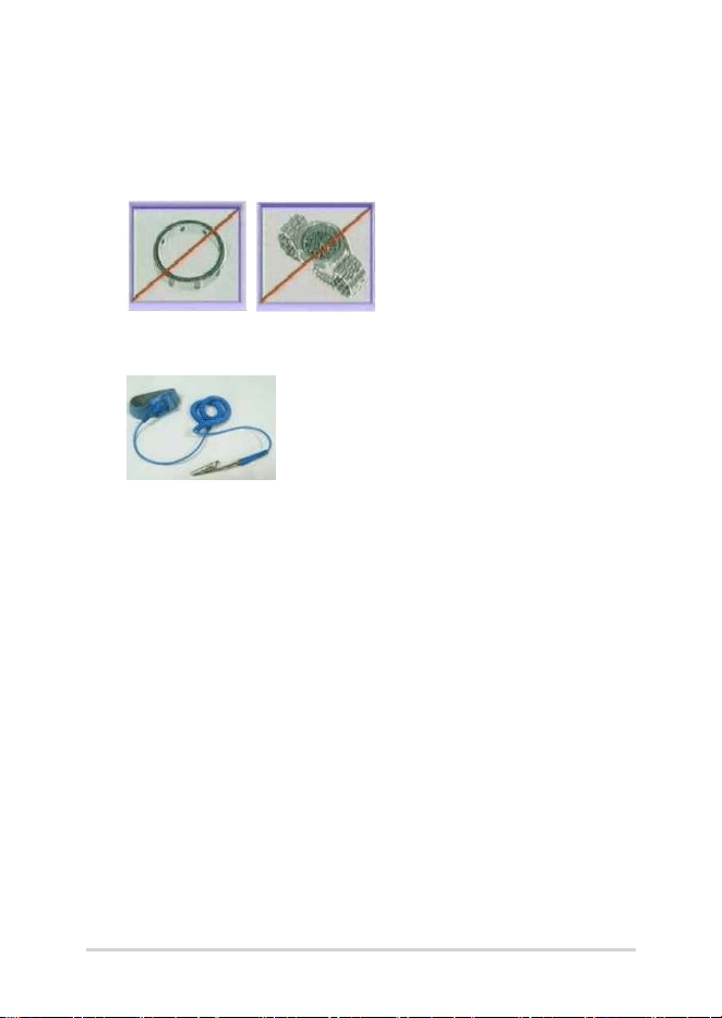
• Remove all rings, watches and any other metal objects from your
hands.
• Always wear a grounding strap on your hand to protect AeroActive
Cooler X Pro (AY2501) from static discharge.
6
Service Manual
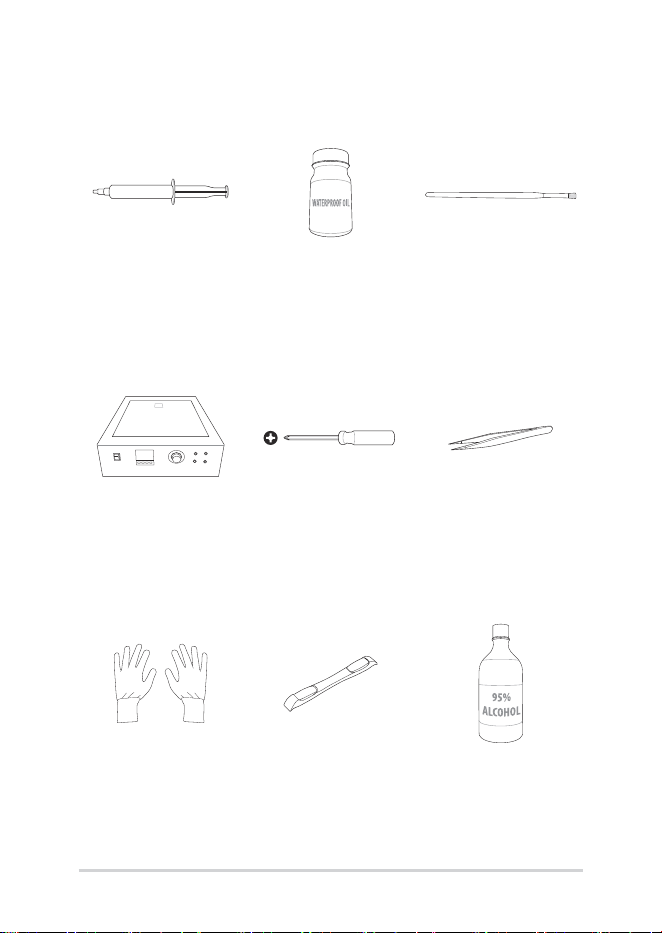
Thermal grease Waterproof oil Brush
Heating platform
(110V/220V)
Screwdriver
(M1.4, 0X50)
ESD tweezers
ESD gloves Plastic blade Alcohol
Repair tools

Service Manual
7
9.7CM
BTB pressing stick
Thermal grease
scraper
8
Service Manual
ASUS AY2501 overview
Top, front, rear, bottom and side features
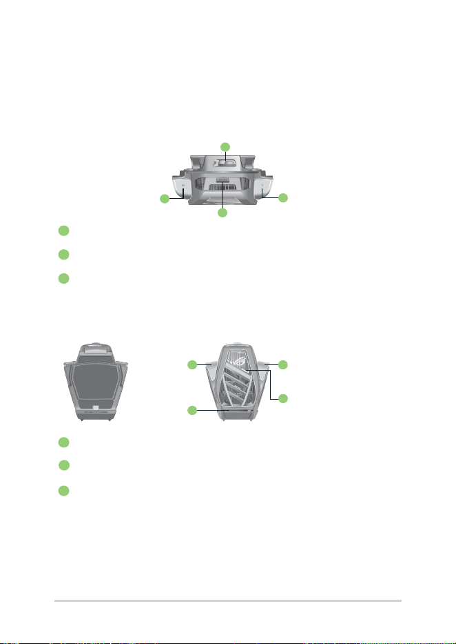
Top view
1
Power button cover
2
Cooler buttons
3
Unlock button
Front view Rear view
1
Cooler buttons
2
Aura light
3
Subwoofer
1
2
2
3
1
3
1
2
Service Manual
9
1
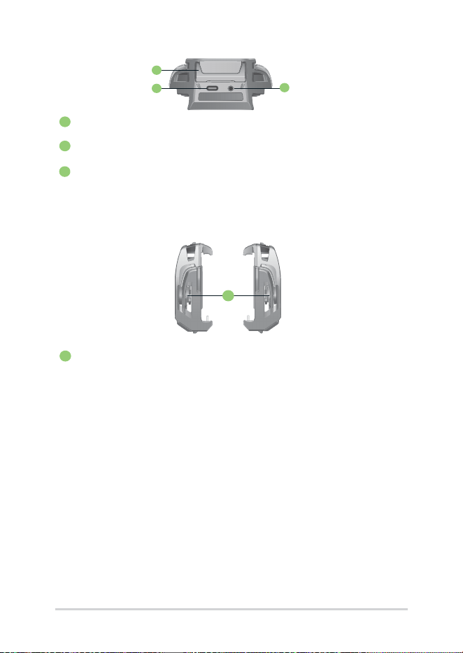
Side view
1
Cooling ns
1
2
3
Bottom view
1
Kickstand
2
USB Type-C port
3
3.5mm headphone jack
10
Service Manual
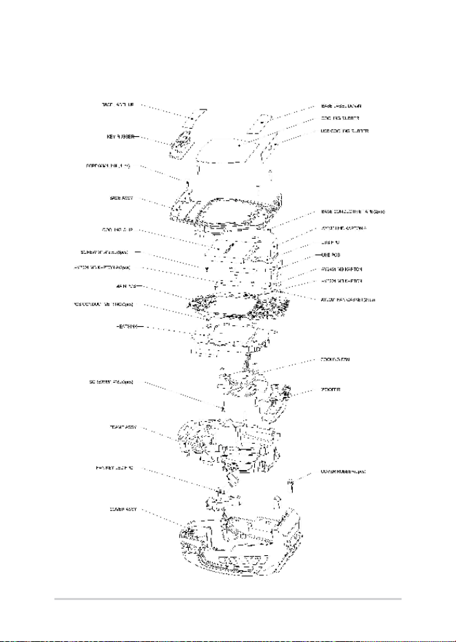
Exploded diagram
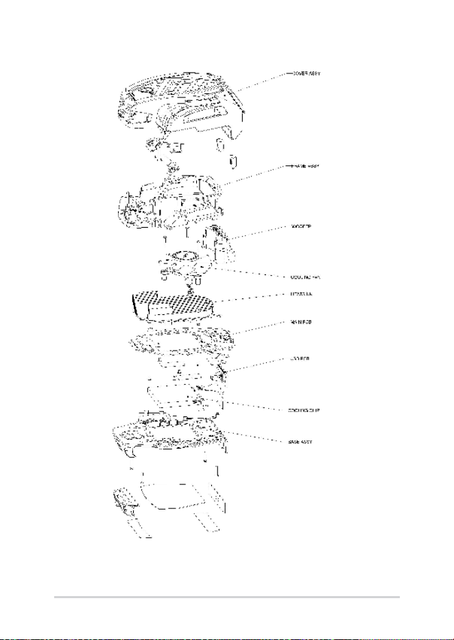
Service Manual
11
12
Service Manual
Major components
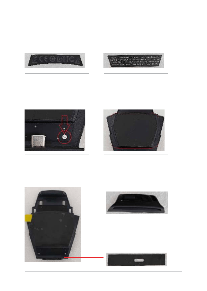
DEVICE LABEL A
ROG SEALED LABEL COOLING RUBBER
BASE ASSY
NOTE: This part is NOT reusable
after disassembly.
DEVICE LABEL B
NOTE: This part is NOT reusable
after disassembly.
NOTE: This part is NOT reusable
after disassembly.
NOTE: This part is NOT reusable
after disassembly.
KEY RUBBER
USB COOLING RUBBER
Service Manual
13
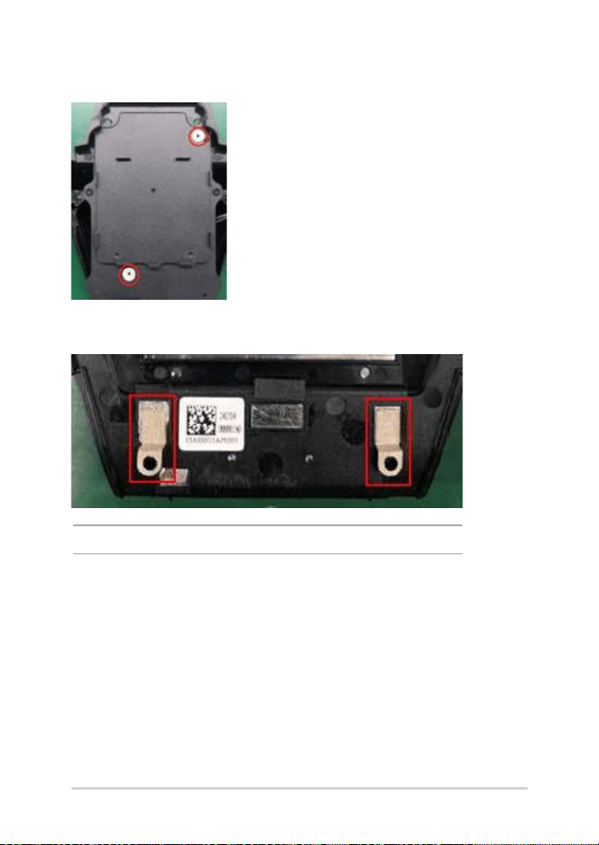
PCB CONDUCTIVE RING
BASE CONDUCTIVE TAPE
NOTE: This part is NOT reusable after disassembly.
14
Service Manual
FAN GASKET
FAN FUNCTION BD
MB KAPTON TOP MB KAPTON
MB KAPTON
Service Manual
15
COOLING CHIP
SUB BD USB FPC R2.0
16
Service Manual
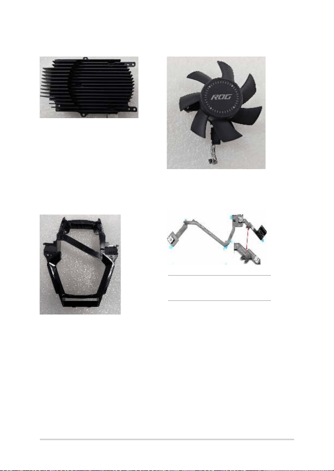
HEATSINK COOLING FAN
FAN LED KEY FPCFRAME ASSY
NOTE: This part is NOT reusable
after disassembly.
Service Manual
17
SCREW M1.4*8L (2.7,0.5) (K) #0
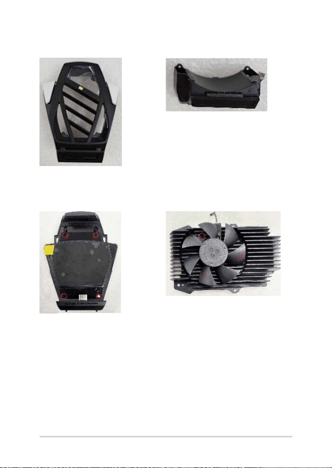
COVER ASSY SR SPK BOX ASSY
18
Service Manual
SCREW M1.4*2.5L (2.8,0.4) (K) #0

Service Manual
19
Disassembly
Caution:
ASUS hereby provides a basic instruction for the disassembly of ASUS
products, i.e. to remove components and materials that require selective
treatments, which are dened by Annex II of the European Union (EU)
Waste Electrical and Electronic Equipment (WEEE) Directive 2002/96/
EC. This instruction is intended for the use of end-of-life recyclers or
treatment facilities. Following is the list of Annex II of EU WEEE Directive
2002/96/EC.
- polychlorinated biphenyls (PCB) containing capacitors in accordance
with Council Directive 96/59/EC of 16 September 1996 on the disposal
of polychlorinated biphenyls and polychlorinated terphenyls (PCB/
PCT),
- mercury containing components, such as switches or backlighting
lamps,
- batteries,
- printed circuit boards of mobile phones generally, and of other devices
if the surface of the printed circuit board is greater than 10 square
centimeters,
- toner cartridges, liquid and pasty, as well as color toner,
- plastic containing brominated ame retardants,
- asbestos waste and components which contain asbestos,
- cathode ray tubes,
- chlorouorocarbons (CFC), hydrochlorouorocarbons (HCFC) or
hydrouorocarbons (HFC), hydrocarbons (HC),
- gas discharge lamps,
- liquid crystal displays (together with their casing where appropriate)
of a surface greater than 100 square centimeters and all those back-
lighted with gas discharge lamps,
- external electric cables,

20
Service Manual
- components containing refractory ceramic bers as described in
Commission Directive 97/69/EC of 5 December 1997 adapting to
technical progress Council Directive 67/548/EEC relating to the
classication, packaging and labelling of dangerous substances,
- components containing radioactive substances with the exception of
components that are below the exemption thresholds set in Article
3 of and Annex I to Council Directive 96/29/Euratom of 13 May 1996
laying down basic safety standards for the protection of the health
of workers and the general public against the dangers arising from
ionizing radiation,
- electrolyte capacitors containing substances of concern (height > 25
mm, diameter > 25 mm or proportionately similar volume)
Service Manual
21
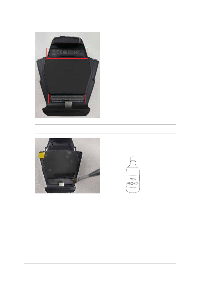
1. Use tweezers to remove the DEVICE LABEL A and DEVICE LABEL B.
NOTE: If the device label is dicult to remove, apply some alcohol.
22
Service Manual
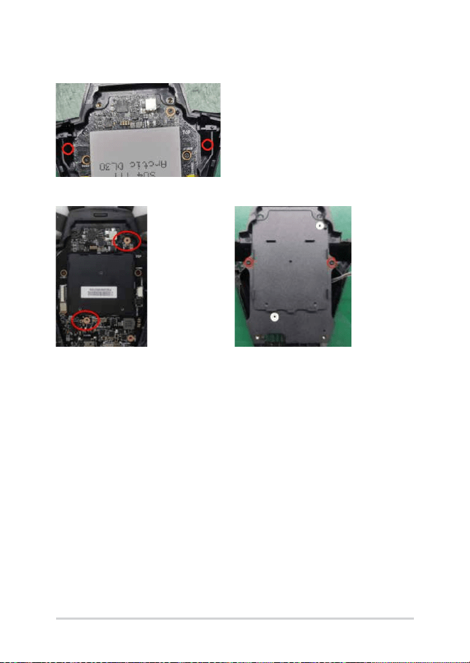
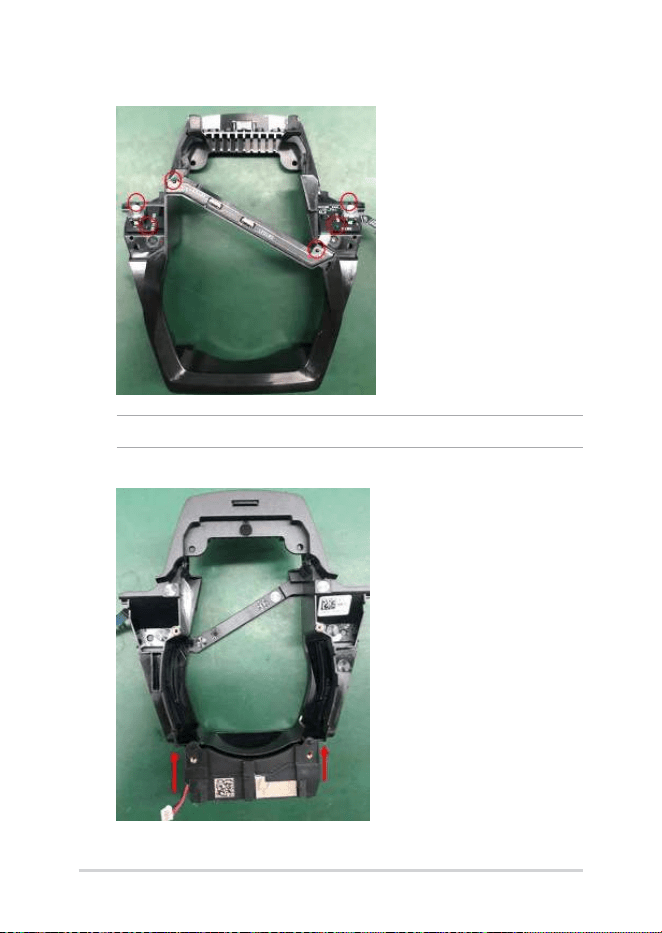
2. Remove the ROG SEALED LABEL and loosen the four M1.4*8L
screws (circled).
ROG SEALED LABEL
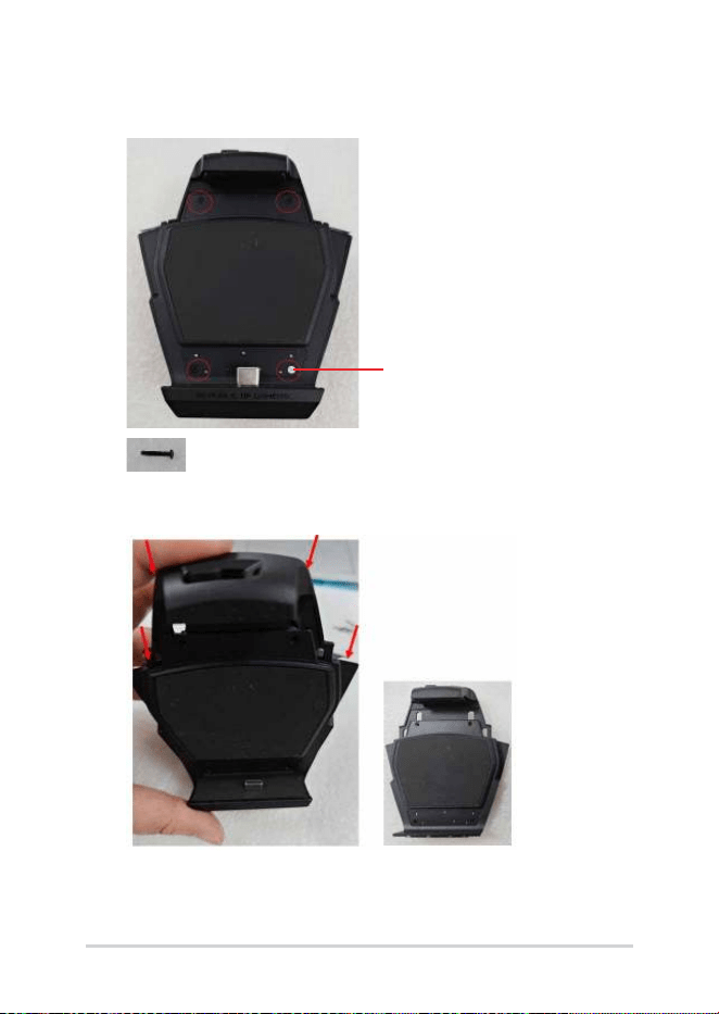
3. Detach the base assembly starting from the points indicated by
the arrows.
’
Service Manual
23
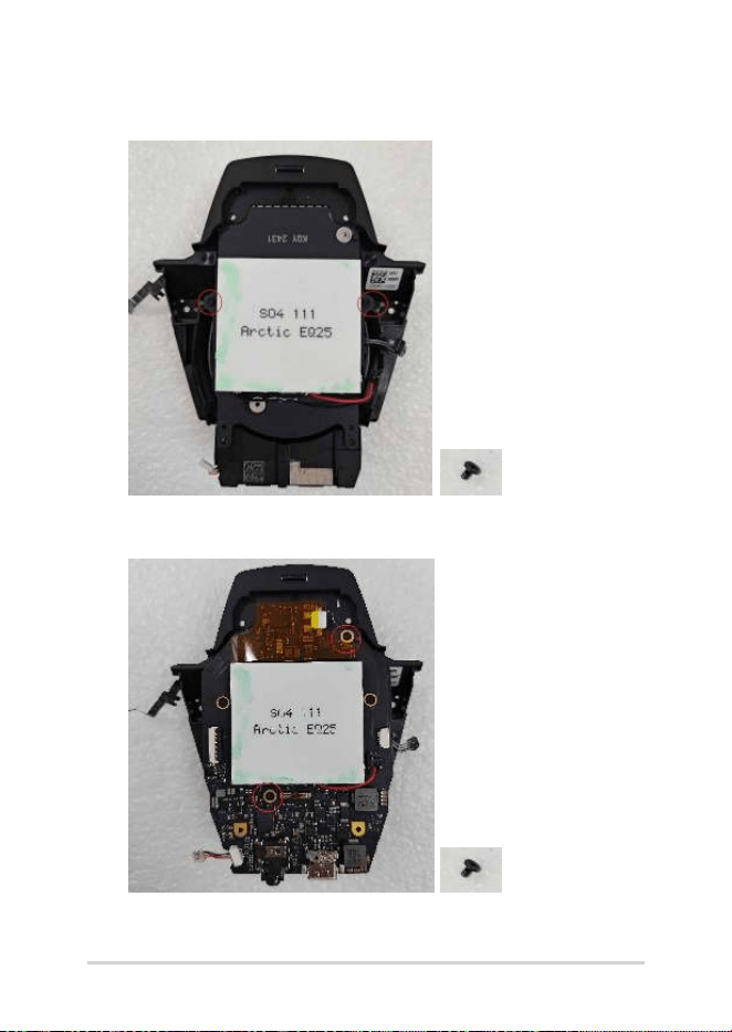
4. Loosen the two M1.4*2.5L screws (circled) and detach the cover
assembly.
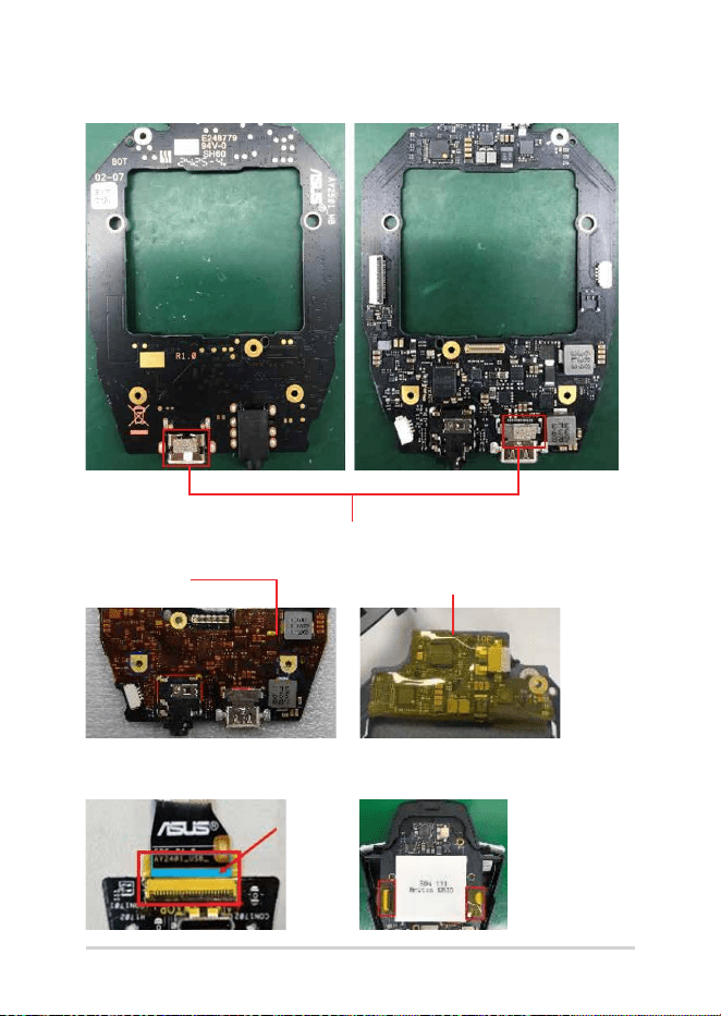
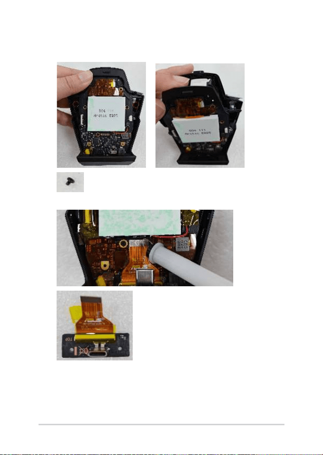
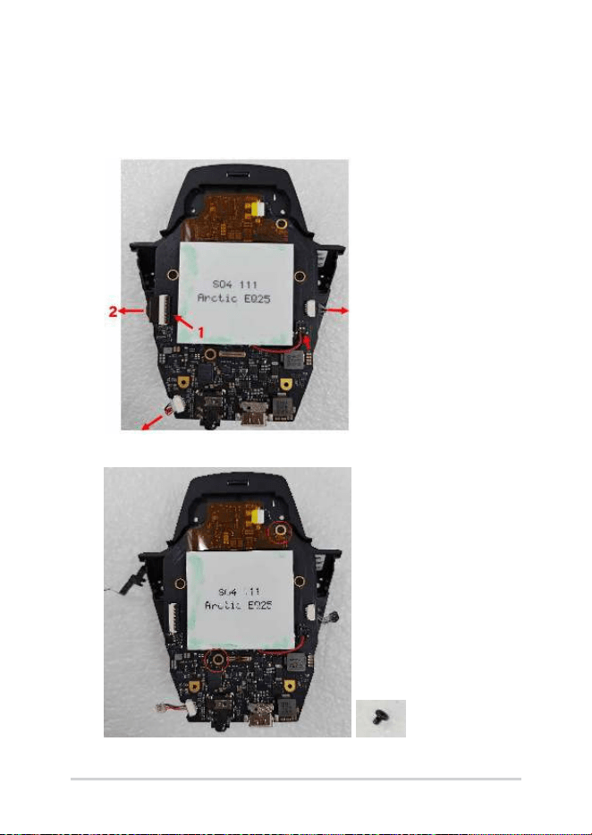
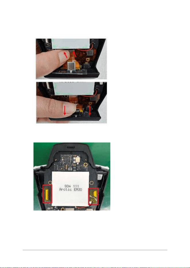
5. Remove the USB FPC and SUB BD from the motherboard.
24
Service Manual
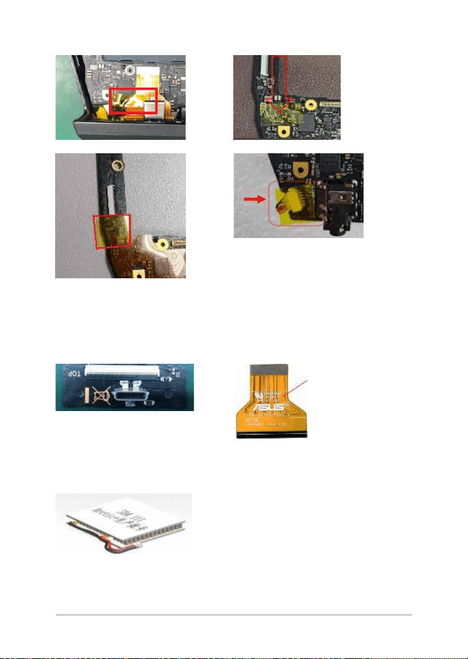
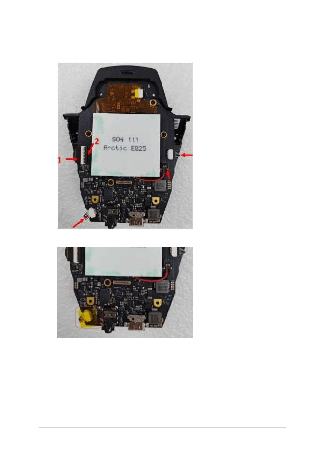
6. 6-1. Remove the motherboard KAPTON tape, and unplug the KEY
LED FPC, FAN cable and SPK BOX cable from the motherboard.
6-2. Lift the Cooling Chip Cable connector and remove it from the
motherboard.
7. Loosen the two M1.4*2.5L screws and remove the motherboard.
Service Manual
25
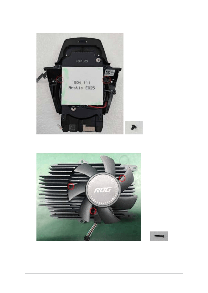
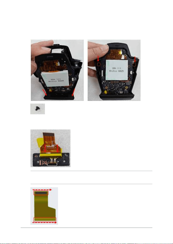
8. Loosen the two M1.4*2.5L screws and remove the FRAME ASSY.
9. Loosen the three M1.4*8L screws and remove the FAN from the
HEATSINK if needed.
26
Service Manual
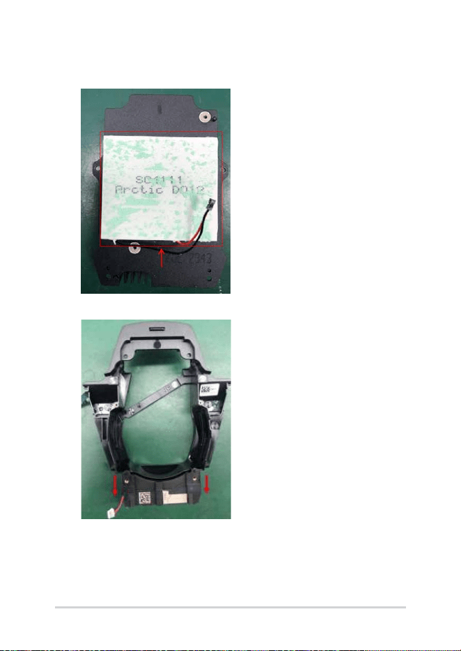
10. Use the Heating Platform to heat up the heatsink for 2 minutes,
then remove the cooling chip if needed.
11. Remove the SPK BOX from the FRAME ASSY if needed.
Service Manual
27
Assembly
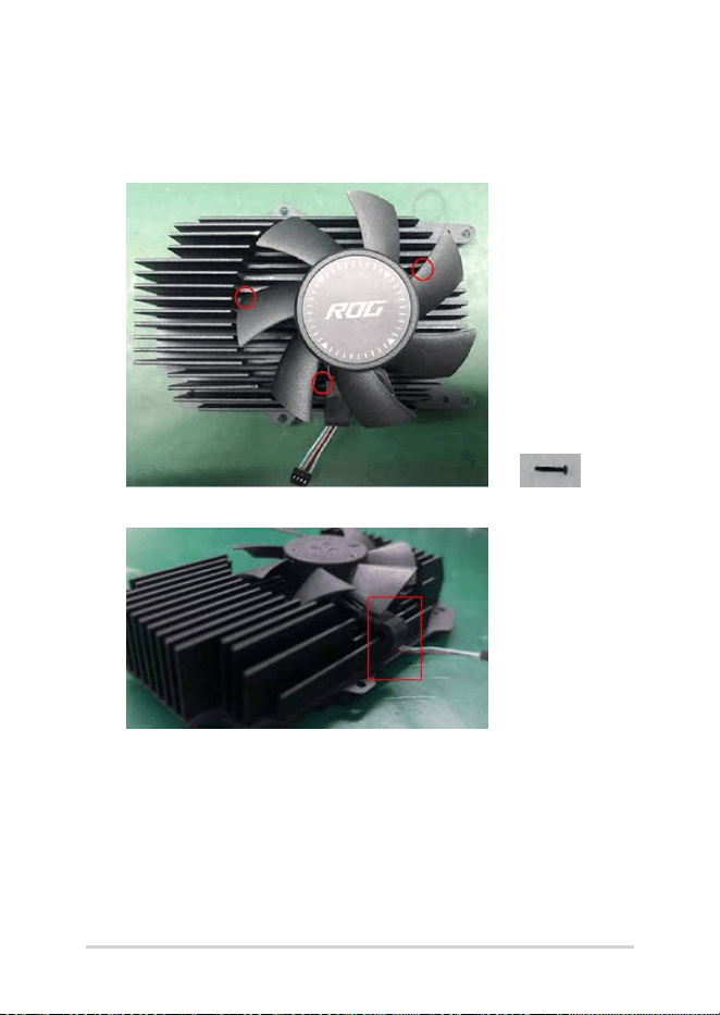
1. Assemble the FAN onto the HEATSINK and secure with three
M1.4*8L screws.
Position the fan wire so that it rests inside the hook.
28
Service Manual
2. Assemble the FAN KEY LED FPC onto the FRAME ASSY if needed.
NOTE: Align the circled points with the alignment columns on the chassis.
3. Assemble the SPK BOX onto the FRAME ASSY.
Service Manual
29
4. Assemble the HEATSINK onto the FRAME ASSY and secure with
two M1.4*2.5L screws.
5. Assemble the motherboard onto the HEATSINK and secure with
two M1.4*2.5L screws.
30
Service Manual
6. Connect the KEY FPC, Cooling Chip Cable, FAN Cable and SPK
cable to the motherboard.
7. Cover the SPK Cable connector with motherboard Kapton tape.
Service Manual
31
8. Install the bottom of the motherboard into the cover, then lay it
at to fully assemble it with the cover. Secure it with two M1.4*2.5L
screws.
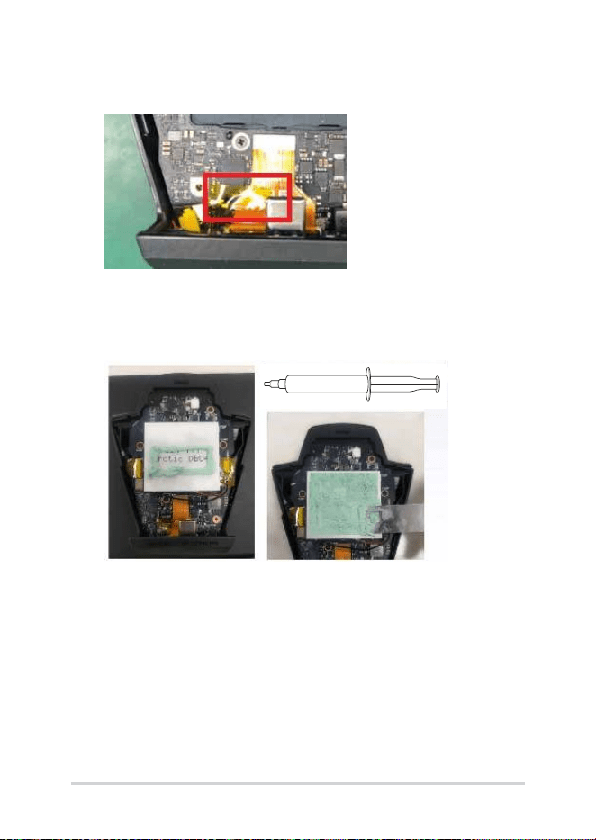
9. Connect the USB FPC to the SUB BD and cover the connector with
motherboard Kapton tape.
NOTE: When replacing a USB FPC, follow the red arrow to apply waterproof
oil to the BTB connector before assembly.
32
Service Manual
10. Connect the USB FPC to the motherboard, and install the SUB BD
into the bottom of the cover.
11. Cover the KEY FPC, Cooling Chip Cable, and FAN Cable connectors
with two pieces of motherboard Kapton tape.
Service Manual
33
12. Cover the motherboard and FPC with a piece of motherboard
Kapton tape.
13. Remove the old thermal grease from the cooling chip and the
back of the BASE ASSY. Apply new thermal grease in the amount
shown in the picture below, and evenly spread it over the cooling
chip.
34
Service Manual
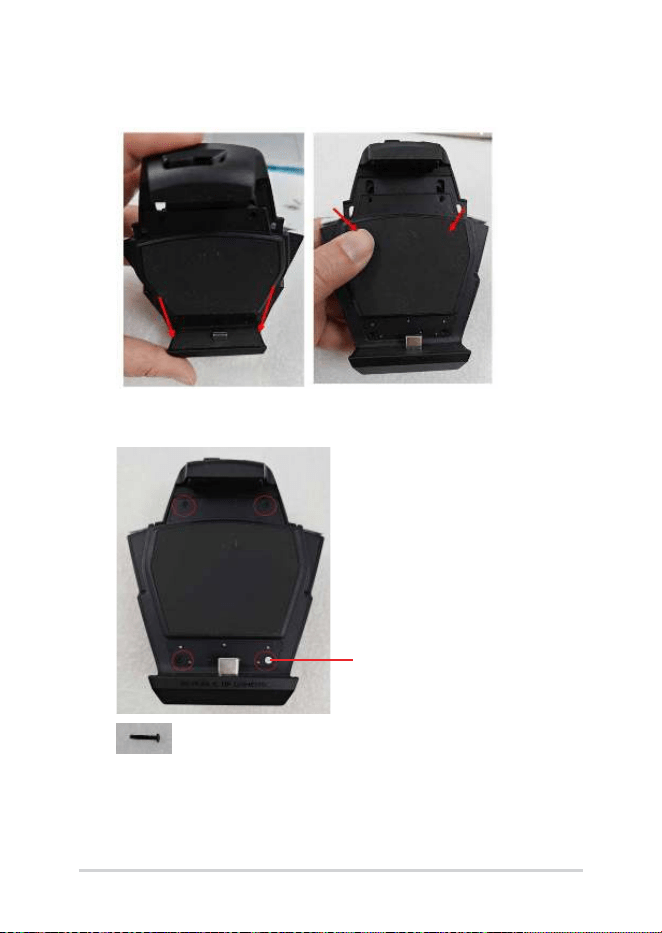
14. Thread the USB male connector through the hole at the bottom of
the BASE ASSY, then snap the entire assembly onto the unit.
15. Secure with four M1.4*8L screws and apply a new ROG SEALED
LABEL.
ROG SEALED LABEL
Service Manual
35
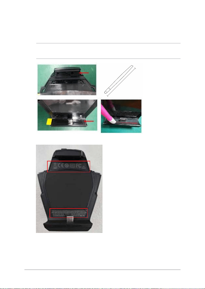
16. Assemble a new KEY RUBBER and a new USB COOLING RUBBER
when replacing a new BASE ASSY.
NOTE: Use the BTB pressing stick to press down on the rubber to ensure it
adheres properly.
9.7CM
11. Paste a new DEVICE LABEL A and a new DEVICE LABEL B.
