&
Assembly Instructions
OWNER’S MANUAL
V. STBR500-20190705
STBR500
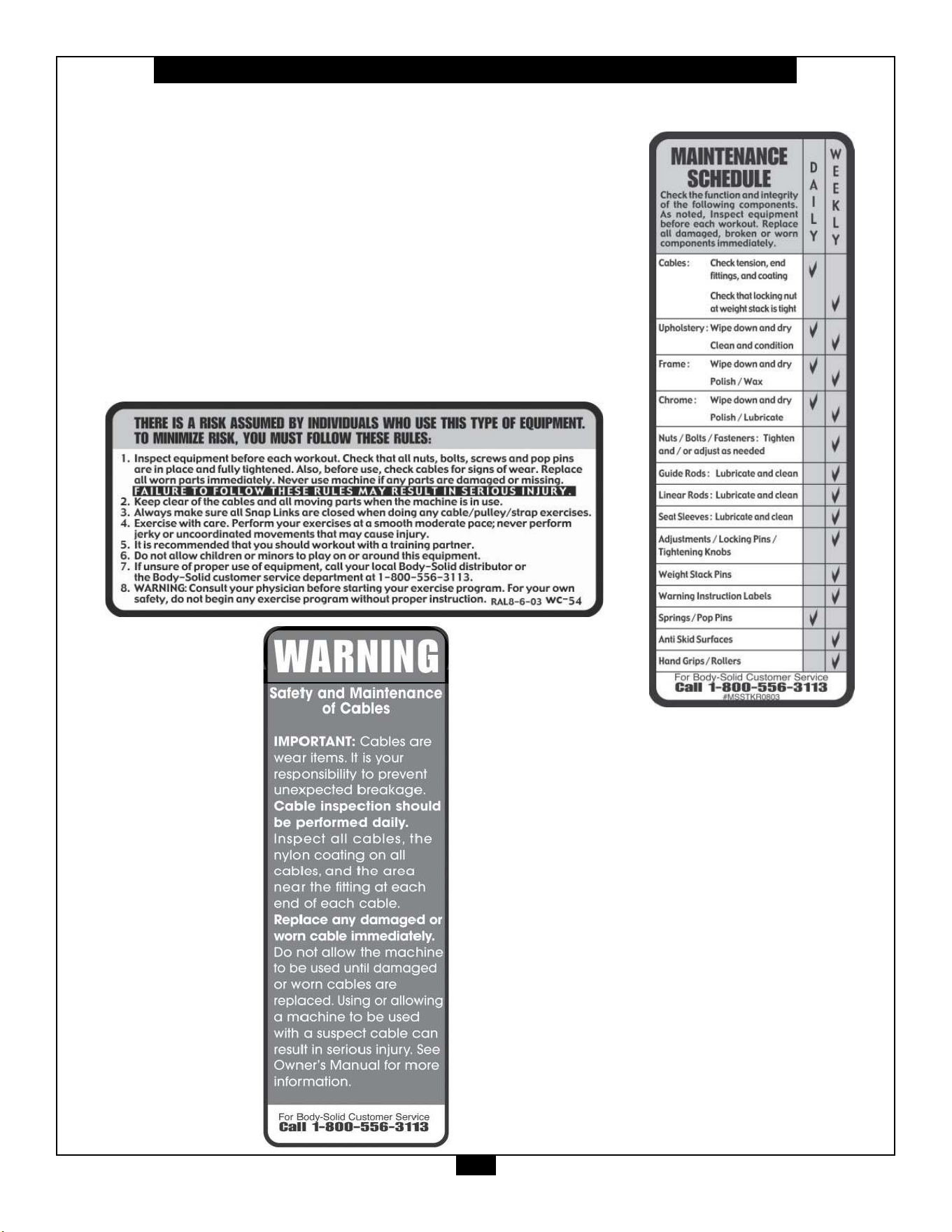
Warning, Safety & Maintenance
2
Be sure that all users carefully read and understand all
warning, safety and maintenance labels on the machine
before each use. Failure to do so may result in death or
serious injury.
It is imperative that you retain this Owner’s Manual and be
sure all warning labels are legible and intact. Replacement
Owner’s Manuals and warning labels are available from your
local Body-Solid dealer.
If you have any questions about the operation, set up or
maintenance of this machine please call our customer service
department at 1 (800) 556-3113.

Table of Contents
3
• SAFETY INSTRUCTIONS.............................. PAGE 4
• PREPARATION............................................... PAGE 5
• HARDWARE ILLUSTRATION......................... PAGE 6
• PART / HARDWARE LIST............................... PAGE 9
• ASSEMBLY INSTRUCTIONS......................... PAGE 10
• EXPLODED VIEW.......................................... PAGE 17
• CONTACT PAGE............................................ PAGE 18

Important Safety Instructions
4
Beforebeginninganytnessprogram,youshouldobtainacompletephysicalexaminationfromyourphysician.
Il est conseille de subir un examen medical complet avant d’entreprendre tout programme d’exercise.
Si vous avez des etourdissements ou des faiblesses, arretez les exercices immediatement.
Antes de comenzar cualquier programma de ejercicios, deberias tener un examen sico con su doctor.
When using exercise equipment, you
should always take basic precautions,
including the following:
m ReadallinstructionsbeforeusingtheSTBR500.
Theseinstructionsarewrittentoensureyoursafety
andtoprotecttheunit.
m Do not remove any safety labels from the
machine.
m Donotallowchildrenonorneartheequipment.
m Usetheequipmentonlyforitsintendedpurpose
asdescribedinthisguide.Donotuseaccessory
attachmentsthatarenotrecommendedbythe
manufacturer.Suchattachmentsmightcause
injuries.
m Wearproperexerciseclothingandshoesforyour
workout,nolooseclothing.
m Keephands,limbs,looseclothing,andlonghairwell
outofthewayofallmovingparts.
m Usecarewhengettingonorotheunit.
m Donotoverexertyourselforworktoexhaustion.
m Ifyoufeelanypainorabnormalsymptoms,stop
yourworkoutimmediatelyandconsultyour
physician.
m Neveroperateunitwhenithasbeendroppedor
damaged.Returntheequipmenttoaservice
centerforexaminationandrepair.
m Neverdroporinsertobjectsintoanyopeningin
theequipment.
m Alwayschecktheunitanditscablesbeforeeach
use.Makesurethatallfastenersandcablesare
secureandingoodworkingcondition.
m Donotusetheequipmentoutdoorsornearwater.
Personal Safety During Assembly
m Beforebeginningassembly,pleasetakethetime
toreadtheinstructionsthoroughly.
m Readeachstepintheassemblyinstructionsand
followthestepsinsequence.Donotskipahead.
Ifyouskipahead,youmaylearnlaterthatyou
havetodisassemblecomponentsandthatyou
mayhavedamagedtheequipment.
m Assembleandoperatethe
STBR500onasolid,
levelsurface.Locatetheunitafewfeetfromthe
wallsorfurnituretoprovideeasyaccess.
TheSTBR500 isdesignedforyourenjoyment.By
followingtheseprecautionsandusingcommonsense,
youwillhavemanysafeandpleasurablehoursof
healthfulexercisewithyourProClubLineLEVERAGE
T-BAR ROW MACHINE.
Afterassembly,youshouldcheckallfunctionsto
ensurecorrectoperation.Ifyouexperienceproblems,
rstrechecktheassemblyinstructionstolocateany
possibleerrorsmadeduringassembly.Ifyouareunable
tocorrecttheproblem,callthedealerfromwhomyou
purchasedthemachineorcall1-800-556-3113forthe
dealernearestyou.
Obtaining Service
PleaseusethisOwner’sManualtomakesurethatall
partshavebeenincludedinyourshipment.When
orderingparts,youmustusethepartnumberand
descriptionfromthisOwner’sManual.Useonly
Body-Solidreplacementpartswhenservicingthis
machine.Failuretodosowillvoidyourwarrantyand
couldresultinpersonalinjury.
Forinformationaboutproductoperationorservice,
checkouttheocialBody-Solidwebsiteat
www.bodysolid.comorcontactanauthorized
Body-SoliddealeroraBody-Solidfactory-authorized
servicecompanyorcontactBody-Solidcustomer
serviceatoneofthefollowing:
Toll Free: 1-800-556-3113
Phone: 1-708-427-3555
Fax: 1-708-427-3556
Hours: M-F 8:30-5:00 CST
E-Mail: [email protected]
Or write to: Body-Solid, Inc.
Service Department
1900 S. Des Plaines Ave.
Forest Park, IL 60130 USA
Retain this Owner’s Manual for future
reference. If you need to order replacement
parts please be prepared to provide the
following information when contacting us so
that we can assist you better.
1. Model Number
2. Place of Purchase
3. Serial Number (S/N)
4. Part # and Description
Preparation
5
ThankyouforpurchasingtheSTBR500.ThisProductispartoftheBody-Solidlineofqualitystrengthtraining
machines,whichletsyoutargetspecicmusclegroupstoachievebettermuscletoneandoverallbody
conditioning. To maximize your use of the equipment please study this Owner’sManual thoroughly.
Body-Solidcontinuallyseekswaystoimprovetheperformance,specicationsandproductmanualsinordertoensurethatonly
superiorproductsarereleasedfromourfactories.Pleasetakethetimetocarefullyreadthroughthismanualthoroughly.Instructions
containedinthisdocumentarenotintendedtocoveralldetailsorvariationspossiblewithBody-Solidequipment,ortocoverevery
contingencythatmaybemetinconjunctionwithinstallation,operation,maintenanceortroubleshootingoftheequipment.Even
thoughwehavepreparedthismanualwithextremecare,neitherthepublishernortheauthorcanacceptresponsibilityforanyerrors
in,oromissionfrom,theinformationgiven.Shouldadditionalinformationberequired,orshouldsituationsarisethatarenotcovered
bythismanual,themattershouldbedirectedtoyourlocalBody-Solidrepresentative,ortheServiceDepartmentatBody-SolidInc.
inForestPark,Illinois.
Required Tools
Thebasictoolsthatyoumustobtainbeforeassembling
the
STBR500includebutarenotlimitedto:
m StandardWrenchSet
m MetricWrenchSet
m AdjustableWrench
Installation Requirements
Followtheseinstallationrequirementswhenassembling
the
STBR500:
Setupthe
STBR500onasolid,atsurface.Asmooth,
atsurfaceunderthemachinehelpskeepitlevel.A
levelmachinehasfewermalfunctions.
Provideamplespacearoundthemachine.Open
spacearoundthemachineallowsforeasieraccess.
Insertallboltsinthesamedirection.Foraesthetic
purposes,insertallboltsinthesamedirectionunless
specied(intextorillustrations)todootherwise.
Leaveroomforadjustments.Tightenfastenerssuchas
bolts,nuts,andscrewssotheunitisstable,butleave
roomforadjustments.Donotfullytightenfasteners
untilinstructedintheassemblystepstodoso.
Fill out and mail the warranty card.
Assembly Tips
Readall“Notes”oneachpagebeforebeginningeach
step.
Whileyoumaybeabletoassemblethe
STBR500using
theillustrationsonly,importantsafetynotesandother
tipsareincludedinthetext.
Somepiecesmayhaveextraholesthatyouwillnotuse.
Useonlythoseholesindicatedintheinstructionsand
illustrations.
NOTE: Withsomanyassembledparts,proper
alignmentandadjustmentiscritical.While
tighteningthenutsandbolts,besuretoleave
roomforadjustments.
CAUTION: Obtainassistance!Ifyoufeellikeyoucan’t
assemblethe
STBR500byyourselfthendo
notattempttodosoasthiscouldresultin
inju
ry.Reviewtheinstallationrequirements
beforeproceedingwiththefollowingsteps.
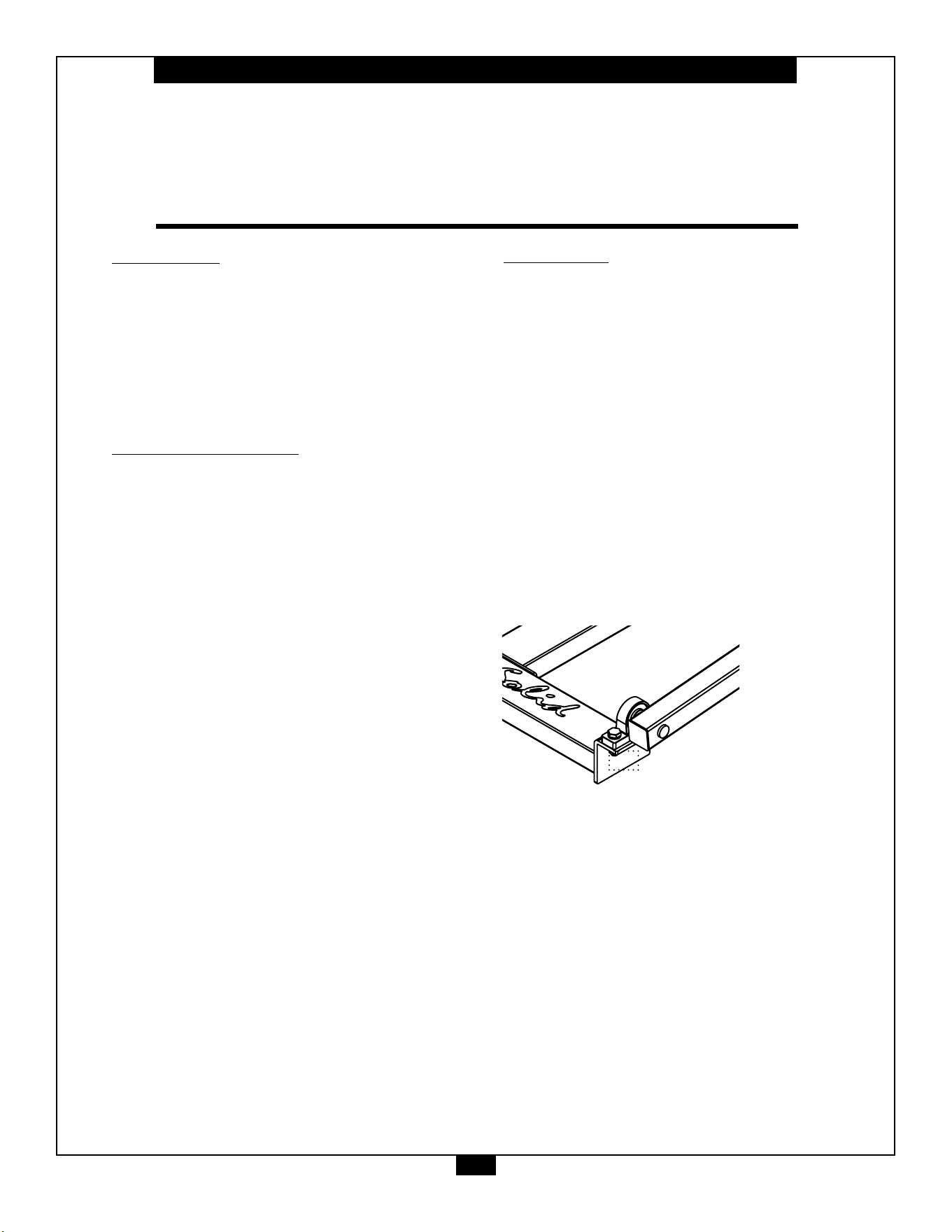
YourS/N#can
befoundhere
↑
45
6
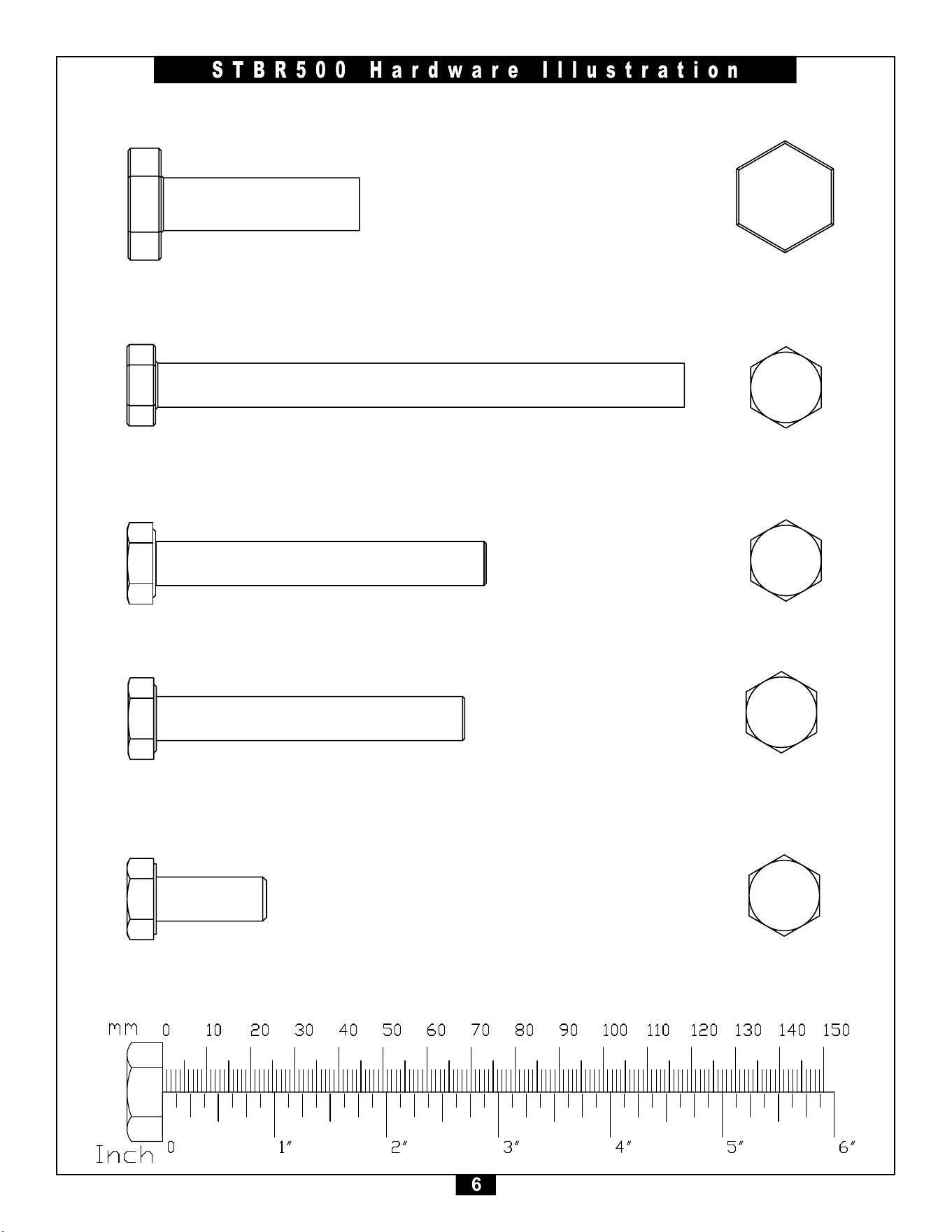
STBR500 Hardware Illustration
Part#2 HEXHEADBOLTM10x125mm QTY. 2
Part#1 HEXHEADBOLTM12x45mm QTY. 4
Part#3 HEXHEADBOLTM10x75mm QTY. 4
Part#4 HEXHEADBOLTM10x70mm QTY. 12
Part#5 HEXHEADBOLTM10x25mm QTY. 2
2 1
A
B
A
B
12
DO NOT SCALE DRAWING
hex cap screw_am
SHEET 1 OF 1
UNLESS OTHERWISE SPECIFIED:
SCALE: 2:1
WEIGHT:
REV
DWG. NO.
A
SIZE
TITLE:
NAME
DATE
COMMENTS:
Q.A.
MFG APPR.
ENG APPR.
CHECKED
DRAWN
FINISH
MATERIAL
INTERPRET GEOMETRIC
TOLERANCING PER:
DIMENSIONS ARE IN INCHES
TOLERANCES:
FRACTIONAL
ANGULAR: MACH
BEND
TWO PLACE DECIMAL
THREE PLACE DECIMAL
APPLICATION
USED ON
NEXT ASSY
PROPRIETARY AND CONFIDENTIAL
THE INFORMATION CONTAINED IN THIS
DRAWING IS THE SOLE PROPERTY OF
<INSERT COMPANY NAME HERE>. ANY
REPRODUCTION IN PART OR AS A WHOLE
WITHOUT THE WRITTEN PERMISSION OF
<INSERT COMPANY NAME HERE> IS
PROHIBITED.
45
7
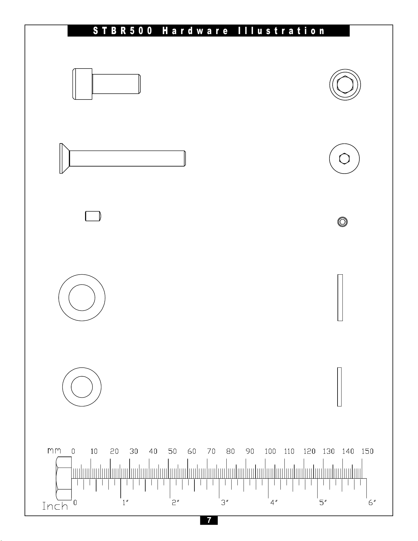
STBR500 Hardware Illustration
Part#6 SOCKETHEADCAPSCREWM10x25mm QTY. 2
Part#7 FLATHEADCAPSCREWM8x65mm QTY. 6
Part#8 SETSCREWM5x6mm QTY. 4
Part#9 FLATWASHERM12 QTY. 8
Part#10 FLATWASHERM10 QTY. 40
45
8
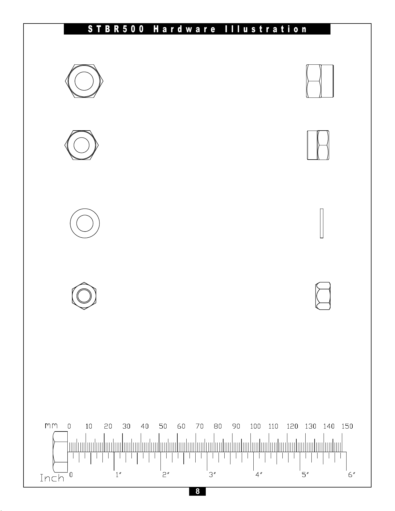
STBR500 Hardware Illustration
Part#11 NYLONLOCKNUTM12 QTY. 4
Part#12 NYLONLOCKNUTM10 QTY. 20
Part#15 FLATWASHERM8 QTY. 6
Part#16 NYLONLOCKNUTM8 QTY. 6

9
STBR500 Parts &Hardware List
Part# Qty Description
A
B
C
D
E
F
G
H
J
K
L
1
2
3
4
5
6
7
8
9
10
11
12
13
14
15
16
1
1
1
2
1
2
1
1
1
1
1
4
2
4
12
2
2
6
4
8
40
4
20
2
2
6
6
FRONT CENTER FRAME
MIDDLE CENTER FRAME
REAR CENTER FRAME
SIDE FRAME
FOOT PLATE
PIVOT ARM
MOUNTING BRACKET
WEIGHT HORN FRAME
HANDLE BAR
FOOT PLATE FRAME
STEEL PLATE
M12x45mmHEXHEADBOLT
M10x125mmHEXHEADBOLT
M10x75mmHEXHEADBOLT
M10x70mmHEXHEADBOLT
M10x25mmHEXHEADBOLT
M10x5mmSOCKETHEADCAPSCREW
M8x65mmFLATHEADCAPSCREW
M5x6mmSETSCREW
M12 FLAT WASHER
M10 FLAT WASHER
M12 NYLON LOCK NUT
M10 NYLON LOCK NUT
RUBBER BUMPER
PILLOW BLOCK BEARING
M8 FLAT WASHER
M8 NYLON LOCK NUT

10
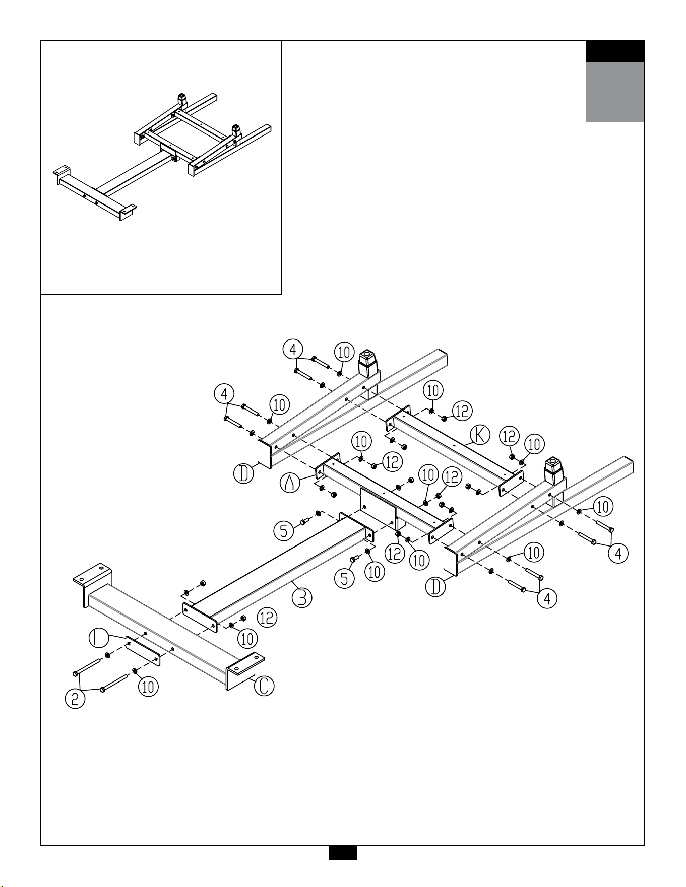
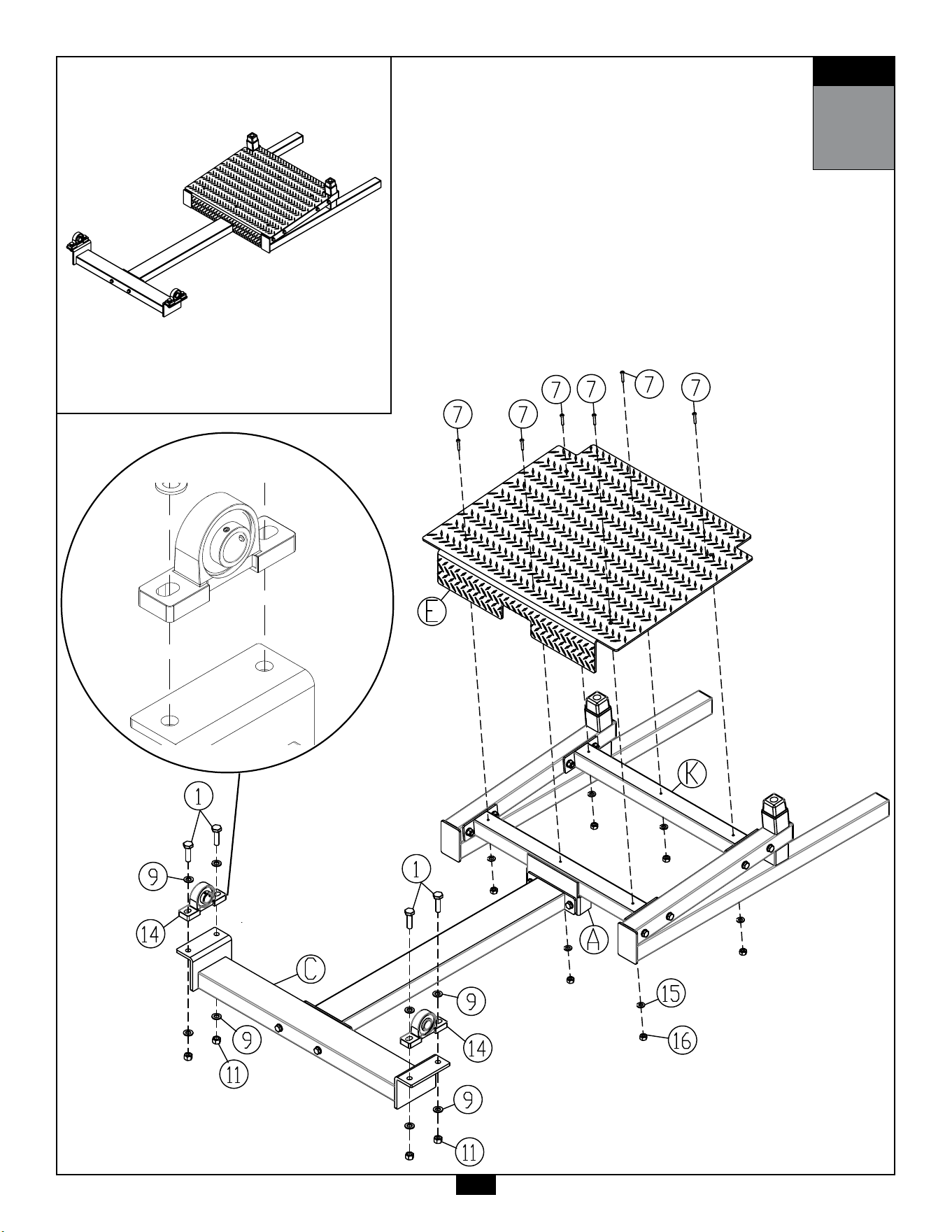
STEP
1
Be careful to assemble all components
in the sequence they are presented.
NOTE:
Wrench tighten ALL hardware at the end of STEP 1D. Some components may be
pre-assembled. Nylon lock nuts will not fully screw onto bolts, they must be wrench
tighten to fully go on.
1A. AttachFrontCenterFrame(A)toMiddleCenterFrame(B)using:
2 - (#5) M10x25mm Hex Head Bolt
4 - (#10) M10 Flat Washer
2 - (#12) M10 Nylon Lock Nut
1B. AttachMiddleCenterFrame(B)toRearCenterFrame(C)using:
2 - (#2) M10x125mm Hex Head Bolt
4 - (#10) M10 Flat Washer
2 - (#12) M10 Nylon Lock Nut
1 - (L) Steel Plate
1C. AttachSideFrames(D)toFrontCenterFrame(A)using:
4 - (#4) M10x70mm Hex Head Bolt
8 - (#10) M10 Flat Washer
4 - (#12) M10 Nylon Lock Nut
1D. AttachFootPlateFrame(K)toSideFrames(D)using:
4 - (#4) M10x70mm Hex Head Bolt
8 - (#10) M10 Flat Washer
4 - (#12) M10 Nylon Lock Nut
STEP
1
AboveshowsStep1assembledandcompleted.
11

12
STEP
2
Be careful to assemble all components
in the sequence they are presented.
NOTE:
Wrench tighten ALL hardware at the end of STEP 2A. Some components may be
pre-assembled. Nylon lock nuts will not fully screw onto bolts, they must be wrench
tighten to fully go on.
2A. AttachFootPlate(E)toFrontCenterFrame(A)&FootPlate
Frame(K)using:
6 - (#7) M8x65mm Flat Head Cap Screw
6 - (#15) M8 Flat Washer
6 - (#16) M8 Nylon Lock Nut
Note #1: It is recommended to put the machine on its side to gain
access to the hardware easier. One person holds the machine
in place while another person tightens the hardware.
2B. AttachPillowBlockBearings(#14)toRearCenterFrame(C) using:
4 - (#1) M12x45mm Hex Head Bolt
8 - (#9) M12 Flat Washer
4 - (#11) M12 Nylon Lock Nut
Note #2: Please make sure the directions of the Pillow Block
Bearing (#14) are installed correctly.
STEP
2
AboveshowsStep2assembledandcompleted.
13
Note #2

14
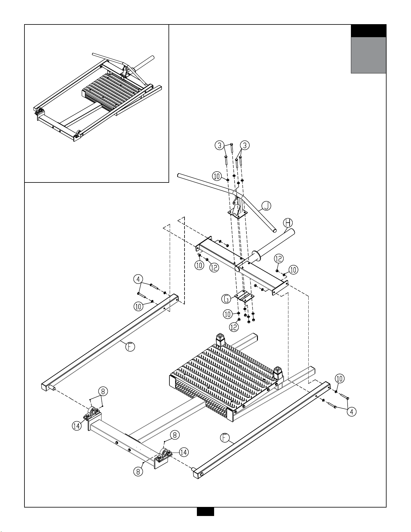
STEP
3
Be careful to assemble all components
in the sequence they are presented.
NOTE:
Wrench tighten ALL hardware at the end of STEP 3C. Some components may be
pre-assembled. Nylon lock nuts will not fully screw onto bolts, they must be wrench
tighten to fully go on.
3A. AttachPivotArms(F)toPillowBlockBearings(#14)using:
4 - (#8) M5x6mm Set Screw
3B. AttachWeightHornFrame(H)toPivotArms(F)using:
4 - (#4) M10x70mm Hex Head Bolt
8 - (#10) M10 Flat Washer
4 - (#12) M10 Nylon Lock Nut
3C. AttachHandleBar(J)toWeightHornFrame(H)using:
4 - (#3) M10x75mm Hex Head Bolt
8 - (#10) M10 Flat Washer
4 - (#12) M10 Nylon Lock Nut
1 - (G) Mounting Bracket
STEP
3
AboveshowsStep3assembledandcompleted.
15

45
16
Notes
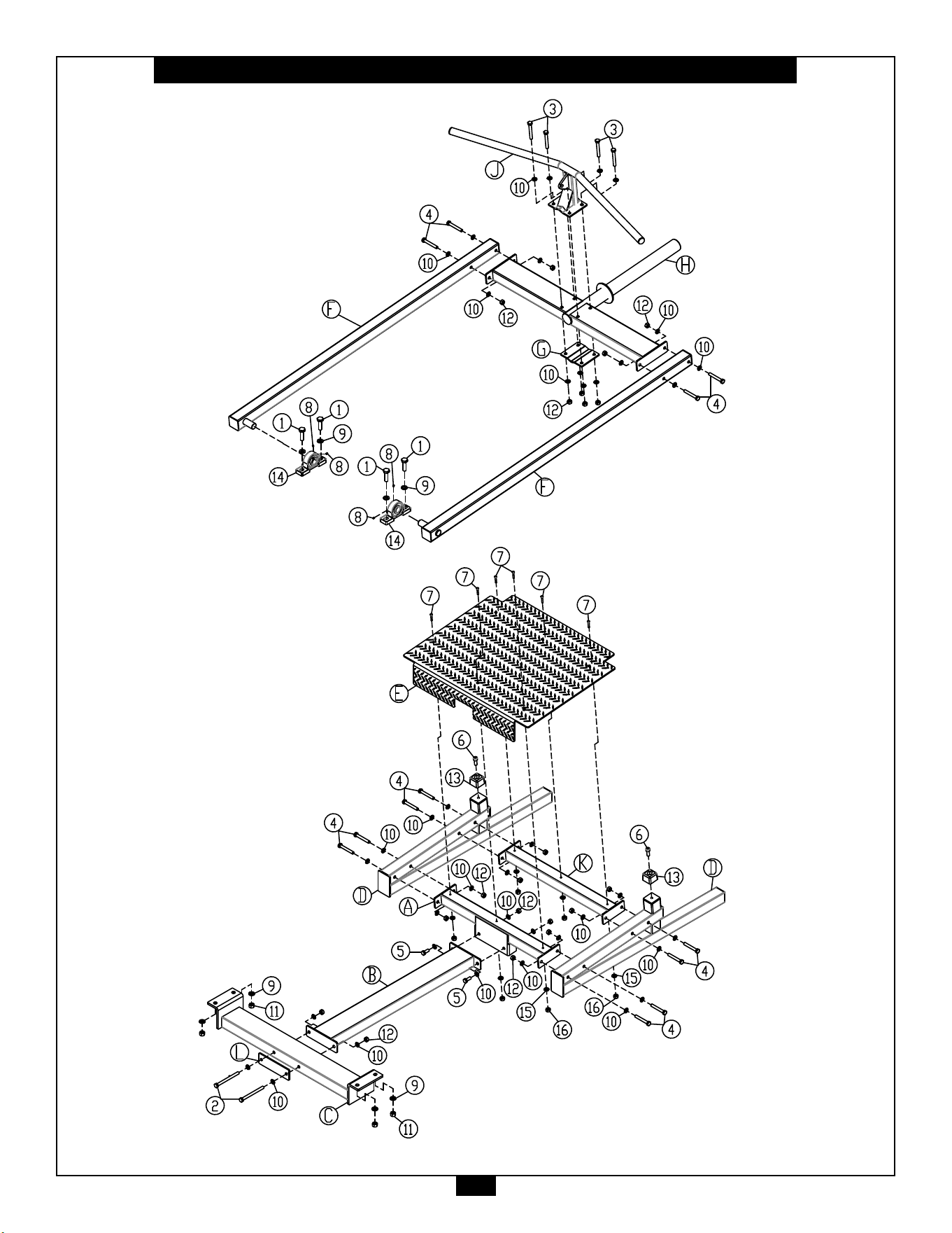
17
STBR500 Exploded View

1900S.DesPlainesAve.
ForestPark,IL60130
Phone:(708)427-3555
Fax:(708)427-3556
Hours:M-F8:30-5:00CST
www.bodysolid.com
Copyright 2009. Body-Solid. All rights reserved. Body-Solid reserves the right to change design and specications when we feel it will improve the product.
Body-Solid machines maintain several patented and patent pending features and designs. All rights reserved on all design patents and utility patents.
PLEASE WRITE YOUR SERIAL NUMBER IN THE BOXES BELOW
S/N#
015197-��-��-����-����
STBR500
